1
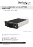
Aluminum 5.25in Bay to 3.5in IDE HDD
Mobile Rack
DRW115ATABK
*DRW115ATABK shown
*actual product may vary from photos
DE: Bedienungsanleitung - de.startech.com
FR: Guide de l'utilisateur - fr.startech.com
ES: Guía del usuario - es.startech.com
IT: Guida per l'uso - it.startech.com
NL: Gebruiksaanwijzing - nl.startech.com
PT: Guia do usuário - pt.startech.com
For the most up-to-date information, please visit: www.startech.com
Manual Revision: 02/27/2012
FCC Compliance Statement
This equipment has been tested and found to comply with the limits for a Class B digital
device, pursuant to part 15 of the FCC Rules. These limits are designed to provide reasonable
protection against harmful interference in a residential installation. This equipment generates,
uses and can radiate radio frequency energy and, if not installed and used in accordance with
the instructions, may cause harmful interference to radio communications. However, there
is no guarantee that interference will not occur in a particular installation. If this equipment
does cause harmful interference to radio or television reception, which can be determined by
turning the equipment off and on, the user is encouraged to try to correct the interference by
one or more of the following measures:
• Reorient or relocate the receiving antenna.
• Increase the separation between the equipment and receiver.
• Connect the equipment into an outlet on a circuit different from that to which the receiver
is connected.
• Consult the dealer or an experienced radio/TV technician for help.
Use of Trademarks, Registered Trademarks, and other Protected Names and
Symbols
This manual may make reference to trademarks, registered trademarks, and other
protected names and/or symbols of third-party companies not related in any way to
StarTech.com. Where they occur these references are for illustrative purposes only and do not
represent an endorsement of a product or service by StarTech.com, or an endorsement of the
product(s) to which this manual applies by the third-party company in question. Regardless
of any direct acknowledgement elsewhere in the body of this document, StarTech.com hereby
acknowledges that all trademarks, registered trademarks, service marks, and other protected
names and/or symbols contained in this manual and related documents are the property of
their respective holders.
Instruction Manual
Table of Contents
Introduction.............................................................................................1
Packaging Contents.................................................................................................................................. 1
System Requirements............................................................................................................................... 1
Installation...............................................................................................2
Installing Hard Drive in the Caddy....................................................................................................... 2
Installing the Bay in the PC..................................................................................................................... 3
Installing the Caddy in the Bay............................................................................................................. 3
Removing the Drive Drawer................................................................................................................... 4
Swap Manager Software........................................................................4
To convert a dynamic disk to a basic disk:........................................................................................ 4
To install the Swap Manager Software:.............................................................................................. 5
Using Your Swap Manager Software................................................................................................... 5
Troubleshooting Swap Manager.......................................................................................................... 6
Monitoring Your Hard Disk Drive and Drawer................................................................................. 6
Specifications...........................................................................................7
Technical Support...................................................................................8
Warranty Information.............................................................................8
Instruction Manual
i
Introduction
This high quality Removable ATA/ IDE Hard Drive Drawer/Mobile Rack delivers a
professional-grade ATA/ IDE hot-swap solution, allowing you to quickly swap ATA/ IDE
hard drives in and out of a computer without having to open the computer case.
Simply install the (included) drive bay into a 5.25in drive bay on the host computer,
then mount a 3.5in IDE HDD in the (removable) caddy. Connecting the IDE hard drive
to the computer is as easy as inserting the caddy into the drive bay, which can be
locked to prevent unauthorized removal of the installed IDE drive.
A practical, time-saving hot swap solution, the drive drawer includes Swap Manager
utility software that lets users swap drives in and out of the host computer without
powering down the computer.
A suitable solution for large volume drives, the HDD drawer supports IDE modes up
to ATA-133, allowing you to swap in large amounts of data in a matter of seconds.
With support for IDE HDD speeds up to 133 MBps, the mobile rack/backplane is fully
compatible with RAID installations to ensure maximum performance and versatility for
enhanced storage applications.
The drive caddy features two front panel ball bearing fans that help keep the enclosed
drive cool, in turn helping to optimize operation while preserving drive lifespan.
To prevent damage to the hard drive(s) while being transferred in and out of the
computer, the drive caddy features shock absorbers and rubber cushioning that help
limit vibration/shock to the drive.
Packaging Contents
•
•
•
•
•
•
1 x Drive caddy
1 x Drive bay
2 x Keys
1 x Screw kit
1 x Swap Manager software CD
1 x Instruction Manual
System Requirements
• Computer with an available 5.25 Inch Drive Bay
• Swap Manager software requires Microsoft® Windows® XP/ 2000/ Server 2003 / Vista / 7
• 1 x 40-pin IDE data cable
• Power Supply with available LP4 Molex power connector
Instruction Manual
1
Installation
Installing Hard Drive in the Caddy
WARNING! Hard drives and storage enclosures require careful handling,
especially when being transported. If you are not careful with your hard disk,
lost data may result. Always handle your hard drive and storage device with
caution. Be sure that you are properly grounded by wearing an anti-static
strap when handling computer components or discharge yourself of any static
electricity build-up by touching a large grounded metal surface (such as the
computer case) for several seconds.
1. Remove the drive caddy from the bay by lifting the handle and sliding the caddy
out of the bay.
2. Remove the top panel from the caddy by pressing the cover release button and
sliding the lid towards the back of the caddy.
3. Connect the short IDE data cable inside the drive caddy to the hard drive.
4. Attach the LP4 Molex power cable inside the drive caddy to the hard drive.
5. Gently place the hard drive in the caddy, making sure that the screw-holes on the
bottom of the hard drive line up with the holes in the caddy.
6. Firmly hold the hard drive to the shock absorber plate and use the four #6-32 x
1/4”(coarse thread) screws to mount your hard drive to the drawer from underneath.
7. Replace the top panel of the drive caddy.
Instruction Manual
2
Installing the Bay in the PC
WARNING! Computer parts can be severely damaged by static electricity. Be
sure that you are properly grounded before opening your computer case.
StarTech.com recommends that you wear an anti-static strap when installing
any computer component. If an anti-static strap is unavailable, discharge
yourself of any static electricity build-up by touching a large grounded metal
surface (such as the computer case) for several seconds.
1. Turn your computer off and any peripherals connected to the computer (i.e. Printers,
external hard drives, etc.). Unplug the power cable from the rear of the power
supply on the back of the computer and disconnect all peripheral devices.
2. Remove the side covers from your system and remove the front cover from an
available 5.25” drive bay (see your computer’s user manual for details, if necessary).
3. Insert the bay into the 5.25” bay slot, making sure that the screw-holes on the side of
the bay line up with the holes in the bay slot.
4. Connect an IDE data and LP4 Molex power cable to the rear of the bay from the
computer systems IDE controller and power supply respectively.
NOTE: The “System” drive cannot be hot-swapped, as it contains the operating
system. Only secondary drives can be hot-swapped through the operating system or
SwapManager software
5. Place the cover back onto the computer case.
6. Insert the power cable into the socket on the power supply and reconnect all other
connectors removed in Step 1.
Installing the Caddy in the Bay
1. With the handle on the caddy fully raised, insert the caddy into the bay.
2. Once inserted as far as it will allow, lower the handle to firmly seat the caddy into
the bay.
3. Use the provided key to lock the caddy into the bay by turning the lock counterclockwise. The caddy must be locked in order for the drive to power up.
Instruction Manual
3
Removing the Drive Drawer
1. Insert the key and turn clockwise to unlock the drive drawer.
2. Lift the handle and gently pull the caddy out of the bay.
NOTE: Do not unlock the drawer when the hard drive is in use (See “Monitoring Your
Hard Disk Drive and Drawer” below). Only power down the drive when the hard drive is
idle. Once you have powered down the hard drive, wait about 15 seconds to let the
hard drive “spin down” before removing the caddy from the bay.
Swap Manager Software
NOTE: Remember that Swap Manager only works on computers running Windows
2000/ XP/ Server 2003/Vista/7
NOTE: Windows 2000/ XP/ Server 2003 users should be aware that Swap Manager
does not support the dynamic disk feature introduced in these versions of Windows. If
you are using the dynamic disk feature, you must convert the volume back to a basic
disk to use Swap Manager.
To convert a dynamic disk to a basic disk:
1. Back up all the data on all the volumes on the disk you want to convert to a basic
disk.
2. Log on as Administrator or as a member of the Administrators group.
3. Click the “Start” button, and then click “Control Panel”.
4. Click “Performance and Maintenance”, click “Administrative Tools”, and then double
click “Computer Management”.
5. In the left pane, click “Disk Management”.
6. Right-click a volume on the dynamic disk that you want to change to a basic disk,
and then click “Delete Volume”.
7. Click Yes when you are prompted to delete the volume.
8. Repeat steps 4 and 5 for each volume on the dynamic disk.
9. After you have deleted all the volumes on the dynamic disk, right-click the dynamic
disk that you want to change to a basic disk, and then click “Convert to Basic Disk”.
NOTE: You must right-click the gray area that contains the disk title on the left side of
the Details pane. For example, right-click Disk 1.
Instruction Manual
4
To install the Swap Manager Software:
1. Insert your Swap Manager CD into your CD drive.
2. AutoPlay should automatically launch and display all of the folders on the CD. If not,
open “My Computer” and double-click on the CD/DVD drive.
3. Enter the folder “AUTOptn”, and double-click the file “SwapManager.exe”.
4. Click Next to continue the installation.
5. Select Yes, I accept to agree to the terms in the license agreement and click Next.
6. Enter a suitable location for the Swap Manager software and click Next. Click Yes to
confirm the location of the installation.
7. Click Finish when the installation is complete and reboot your computer to allow
the changes to take effect.
Using Your Swap Manager Software
The following is intended to provide you with an introduction to your Swap Manager
software. For detailed instructions and troubleshooting tips, consult the material
provided on the Swap Manager CD.
• Start Swap Manager by double-clicking on the Swap Manager icon. This will bring
up the Swap Manager window.
• The Swap Manager window displays a list of all the drives attached to your
computer. The window also lists information about each drive’s IDE channel.
• Remember that while the window lists all drives for your computer, you can only
swap drives attached to the secondary IDE channel.
• If possible always keep the Swap Manager open if you are planning to swap drives.
It can be minimized, but it should not be closed.
• To remove a drive, bring up the Swap Manager window and click on the Swap
Out button above the drive information. Wait a few seconds then remove the
drive (see “Removing the Drive Drawer”) or follow instructions provided by the
drive manufacturer. Click on the “Swap All” In button to refresh the Swap Manager
information. The drive information should now be removed from the Swap
Manager.
• To add a drive, add your drive according to the instructions on page 5 or according
to instructions provided by your drive manufacturer. Bring up the Swap Manager
window and click on the Swap All In button to refresh the Swap Manager. It may
take a few seconds to properly register all the new information. You should now see
your new drive listed in the Swap Manager.
Instruction Manual
5
Troubleshooting Swap Manager
If you have installed a new drive but there is no new icon listed in Swap Manager, first
make sure that you have clicked the Swap In icon to let Swap Manager know that there
is a new drive. If that does not work, check the following:
• Make sure that the hardware is properly installed and that all cables are properly
connected and firmly seated.
• Make sure that the drive bay is connected to the secondary ATA/ IDE channel. The
primary ATA/ IDE channel is not accessed by Swap Manager.
• Make sure that the drive caddy is firmly seated in the bay and that the bay has been
locked. If the bay is not locked, no power will be supplied to the drive and Swap
Manager will not detect it.
Monitoring Your Hard Disk Drive and Drawer
The status LED is located on the right side of the drive drawer. It is your best indication
of the hard drive’s status, and is lit when the drawer is successfully inserted and locked
into the caddy.
The Fan Status LED located on the left side of the drive drawer indicates fan failure.
When lit up, a problem with the cooling fans has been detected.
NOTE: It is recommended that you avoid removing a drawer during hard disk activity,
as doing so could damage the drive and/or data.
Instruction Manual
6
Specifications
Number of Drive Bays
1
Host Interface
ATA/ IDE (pass through)
1 x 40-pin IDE data male
Host Connectors
1 x 4-pin LP4 Molex male
1 x Power
LEDs
1 x Fan Failure
Compatible Hard Drives
3.5in ATA/ IDE
Fans
2 x 40mm (ball bearing)
Insertion Rating
7, 000 cycles
Enclosure Material
Aluminum
Dimensions (LxWxH)
220.0mm x 148.0mm x 41.0mm
Weight
980g
Instruction Manual
7
Technical Support
StarTech.com’s lifetime technical support is an integral part of our commitment to
provide industry-leading solutions. If you ever need help with your product, visit
www.startech.com/support and access our comprehensive selection of online tools,
documentation, and downloads.
For the latest drivers/software, please visit www.startech.com/downloads
Warranty Information
This product is backed by a two year warranty.
In addition, StarTech.com warrants its products against defects in materials
and workmanship for the periods noted, following the initial date of purchase.
During this period, the products may be returned for repair, or replacement with
equivalent products at our discretion. The warranty covers parts and labor costs only.
StarTech.com does not warrant its products from defects or damages arising from
misuse, abuse, alteration, or normal wear and tear.
Limitation of Liability
In no event shall the liability of StarTech.com Ltd. and StarTech.com USA LLP (or their
officers, directors, employees or agents) for any damages (whether direct or indirect,
special, punitive, incidental, consequential, or otherwise), loss of profits, loss of business,
or any pecuniary loss, arising out of or related to the use of the product exceed the
actual price paid for the product. Some states do not allow the exclusion or limitation
of incidental or consequential damages. If such laws apply, the limitations or exclusions
contained in this statement may not apply to you.
Instruction Manual
8
Hard-to-find made easy. At StarTech.com, that isn’t a slogan. It’s a promise.
StarTech.com is your one-stop source for every connectivity part you need. From
the latest technology to legacy products — and all the parts that bridge the old and
new — we can help you find the parts that connect your solutions.
We make it easy to locate the parts, and we quickly deliver them wherever they need
to go. Just talk to one of our tech advisors or visit our website. You’ll be connected to
the products you need in no time.
Visit www.startech.com for complete information on all StarTech.com products and
to access exclusive resources and time-saving tools.
StarTech.com is an ISO 9001 Registered manufacturer of connectivity and technology
parts. StarTech.com was founded in 1985 and has operations in the United States,
Canada, the United Kingdom and Taiwan servicing a worldwide market.