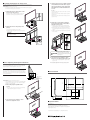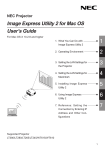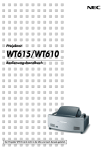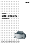
1
M Assembling the Panel Screen WT40SN 40" Panel Screen WT40SN Assembly Instructions 1. Mount the two lateral bars to the frames. We greatly appreciate your purchase of this NEC WT40SN flat panel screen. Read these instructions carefully to ensure proper assembly. * The WT40SN is a panel screen exclusively for use with mirror projection type projectors. It can be used in combination with the separately sold dedicated projector stand to form a stand with integrated screen. M Be sure to read this section before using. Slide the lower lock fittings to the approximate positions shown on the diagram and fasten them in place with the M5 × 50 screws. M5 × 50 screw • About the pictograms Pictograms are used in these assembly instructions and on the product to ensure proper, safe use of the product and prevent injury to you and others as well as damage to property. The pictograms and their meanings are described below. Be sure to understand them fully before reading the instructions. WARNING Failure to heed these indications and handling improperly could lead to physical accidents, including death or major injury. CAUTION Failure to heed these indications and handling improperly could lead to physical injury or damage to surrounding property. Examples of pictograms Lateral bar Lower lock fitting Frame 2-1. W hen mounting to a separately sold dedicated stand The symbol urges caution (including warnings). A concrete description of the caution is indicated on the diagram. The symbol indicates instructions that must be performed. A concrete description of the instruction is indicated on the diagram. • Keep magnetic recording media at least 10 cm away. The screen is attached to the board by magnet. Placing magnetic tickets, credit cards, floppy discs, video tapes, cassette tapes or other magnetic recording media within 10 cm from the screen could lead to loss of or damage to the recorded data. • Do not apply adhesive tape or the like to the screen’ s surface. If cellophane or other adhesive tape is accidentally stuck on the screen surface, peel it off carefully, being sure that none of the adhesive remains. If there is any adhesive on the screen surface, wipe it off carefully using a neutral detergent. • Do not make any modifications. Doing so could lead to accidents due to the screen falling. • Be sure to tighten the product’s screws securely. Failure to do so could lead to the screen falling, resulting in injury or damage to the equipment. • Do not use the screen outdoors. Wind could cause the screen to tip over or fall, resulting in injury or damage to the equipment. CAUTION • Heed the items below. Failure to heed them could lead to the screen falling or tipping over, resulting in injury or damage to the equipment. · Do not place on sloped surfaces or in unstable places. · Do not hang from the screen, hook objects onto it or push it. · Do not climb onto the screen. · Do not place any objects other than the designated projector on the screen’s plate. • Do not place the screen in direct sunlight or other places exposed to high temperatures, in humid or dusty places, or in places where it will be exposed to water or oil. • Do not touch the screen surface. Dirt on the screen will reduce the picture quality. If the screen surface is dirty, apply some neutral detergent dissolved in about 20 parts of water to a soft cloth and wipe off the dirt gently. Avoid using benzene or thinner, as they could mar the surface. Plate Before mounting, lock the dedicated stand’s casters, lower the top panel and tighten the height adjustment knobs securely so that the stand is stable. Line up the panel screen fixing holes in the dedicated stand with the holes in the frames. Place the plate on the frames and fasten it to the dedicated stand using the M6 × 35 screws. * The stands included with the panel screen are not used, so store them in a safe place. M6 × 35 screw [Dedicated stand] Panel screen fixing holes NOTE • Do not scratch the screen with metal objects, etc. The screen’s surface is protected with an extremely hard coating, but as a plastic material is used, rubbing hard objects such as metal against it could scratch it. Frame CAUTION The symbol indicates actions that should not be performed. A concrete description of the forbidden action is indicated on the diagram. WARNING Attach the frames and plate to the dedicated stand. M6 × 35 screw 2-2. W hen using the screen alone Mount the plate and stands to the frames. Line up the frames with the screw holes in the plate, insert the M6 × 35 screws and fasten to the stands’ screw holes. Frame • When transporting the screen, do so in the same packaged conditions as when it was purchased to avoid scratches and damage. WT40SN-0804K-01 Plate Stand M Checking the Package Contents 3. Insert the screen unit’s upper lock fitting into the frame and fasten temporarily with the height adjustment knobs. Check that the following parts are included in the package. Caps: 2 Screen unit Upper lock fitting Fasten the screen unit at the position of the stoppers in the frame. Stopper Frames Lateral bars: 2 Frames: 2 Plate: 1 Stands: 2 Height adjustment knob 4. Fasten the bottom edge of the screen to the frames. Screen unit: 1 Wires: 2 Frame bottom edge fitting Slide the lower lock fittings and line them up with the screw holes in the frame bottom edge fitting. Fasten using two M6 × 10 screws. Frames Lower lock fitting 3 × 10 screws: 2 M4 × 8 screws (with washers): 4 M6 × 10 screws M5 × 50 screws: 4 M6 × 35 screws: 4 M6 × 10 screws: 4 Height adjustment knobs: 2 5. Attach the caps to the frames. Insert the caps over the upper tips of the frames. Fasten them with the 3 × 10 screws. The caps prevent the screen unit from coming off. Cap This completes assembly of the panel screen. Frames 3 × 10 screw M Setting the Projector on the Screen 3. Slide the projector left or right, forward or backward so that the lower edge of the projected image (in the horizontal direction) fits over the full width of the screen. The setting procedure is the same when the screen is mounted on the dedicated stand. Preparations: Shorten the projector’s feet. Turn the four feet clockwise (for the WT610/WT615) and make them as short as possible. For details, refer to the projector’s user’s manual. 1. Attach the wires to the bottom of the projector (in two places). Point the flat surface of the fitting towards the projector and attach to the rear of the projector using M4 × 8 screws. In case … The picture is shifted left or right: Slide left or right to center the picture on the screen. The picture is too small: Slide towards the back (the position of projection rises). The picture is too large: Slide towards the front (the position of projection lowers). C B A 4. Adjust the screen height so that the projected image (in the vertical direction) fits on the screen. 2. Attach the wires to the plate (in two places). Pass the wires through the holes in the plate. Fasten the wires to the plate’s wire lock screw holes using M4 × 8 screws. Holding the screen’s lateral bar, loosen the left and right height adjustment knobs (by turning them counterclockwise). Adjust the height of the screen, holding it with both hands near the height adjustment knobs (keep it level as you raise or lower it). Tighten the left and right height adjustment knobs (by turning them clockwise). C B A CAUTION Be sure to attach the projector using the wires to prevent the projector from falling. Wire M4 × 8 screw Wire hole CAUTION Adjust the height carefully so that the screen does not tip over. You could be injured and the equipment damaged if the screen tips over. C B A 5. Use the projector’s FOCUS + and – buttons to accurately adjust the focus. M Fine-adjusting the Projection Position * If there is keystone (trapezoidal) distortion, adjust using the projector’s feet. This completes adjustment of the projection position. When the projector is placed at the center of the plate, the picture is projected at approximately the center of the screen. Fine-adjust the projection position so that the picture fits on the screen. REMARKS The projection distance (between the projector’s rear panel and screen) is approximately 6.4 cm, the height of the bottom edge of the screen (between the projector’s bottom panel and the screen’s bottom edge) is approximately 35.4 cm (calculated values). M External View Units: mm 35.4 cm Bottom panel of projector 6.4 cm Rear panel of projector Preparations: Project an image from the projector. See the “Installation and Connections” and “Projecting Images (Basic Operation)” sections of the projector’s user’s manual for complete instructions on projecting images. 668 Effective screen area 1085 618 1. Place the projector parallel to the screen. • Be sure to shorten the projector’s feet. The projected image will be distorted if the projector is at an angle. 824 Parallel 345 476 2. Use the projector’s FOCUS + and – buttons to adjust the focus. M Specifications C B A Screen gain: 2.0 Suited viewing range: 45° (1/2 screen gain) Effective screen dimensions: 824 (width) × 618 (height) mm External dimensions: 874 (width) × 476 (depth) × 1085 (height) mm Weight: Approx. 5.8 kg * Specifications and design subject to change without notice. 438 874