1
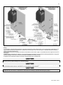
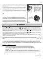
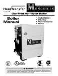
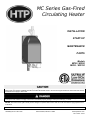
MC Series Gas-Fired
Circulating Heater
INSTALLATION
START-UP
MAINTENANCE
PARTS
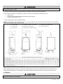
Models
MC50 / MC80
MC99 / MC120
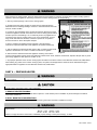
When installing models manufactured after July 7, 2008, you will notice additional selections on the control installer menu that will not
apply to this unit. DO NOT CHANGE THESE FACTORY SETTINGS. Refer to the Control Program Reference Chart within this manual
for selections that apply to this model.
This manual must be used by a qualified installer/service technician. Read all instructions in this manual before installing. Perform steps
in the given order. Failure to comply could result in substantial property damage, severe personal injury, or death.
NOTICE: HTP reserves the right to make product changes or updates without notice and will not be held liable for typographical errors
in literature.
NOTE TO CONSUMER: PLEASE KEEP ALL INSTRUCTIONS FOR FUTURE REFERENCE.
120 Braley Rd. P.O. Box 429
East Freetown, MA 02717-0429
www.htproducts.com
LP-171 Rev. 3.3.15
2
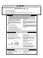
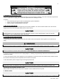
IF THE INFORMATION IN THIS MANUAL IS NOT FOLLOWED EXACTLY, A FIRE OR EXPLOSION MAY RESULT, CAUSING
PROPERTY DAMAGE, PERSONAL INJURY, OR LOSS OF LIFE. DO NOT STORE GASOLINE OR OTHER FLAMMABLE VAPORS
AND LIQUIDS IN THE VICINITY OF THIS OR ANY OTHER HEATER.
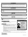
WHAT TO DO IF YOU SMELL GAS
Do not try to light any appliance.
Do not touch any electrical switch.
Do not use any phone in your building.
Immediately call your gas supplier from a neighbor’s phone. Follow the gas supplier’s instructions.
If you cannot reach your gas supplier, call the fire department. Installation and service must be provided by a qualified installer,
service agency, or the gas supplier.
LP-171 Rev. 3.3.15
3
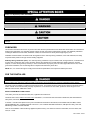
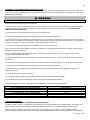
The following defined terms are used throughout this manual to bring attention to the presence of hazards of various risk
levels, or to important product information.
DANGER indicates an imminently hazardous situation which, if not avoided, will result in death or serious injury.
WARNING indicates a potentially hazardous situation which, if not avoided, could result in death or serious injury.
CAUTION indicates a potentially hazardous situation which, if not avoided, may result in minor or moderate injury.
CAUTION used without the safety alert symbol indicates a potentially hazardous situation which, if not avoided, may result in property
damage.
FOREWORD
This manual is intended to be used in conjunction with other literature provided with the MC Series Gas-Fired Heater. This includes all
related control information. It is important that this manual, all other documents included with this system, and additional publications
including the National Fuel Gas Code, ANSI Z223.1-2002, be reviewed in their entirety before beginning any work.
Installation should be made in accordance with the regulations of the Authority Having Jurisdiction, local code authorities, and utility
companies which pertain to this type of water heating equipment.
Authority Having Jurisdiction (AHJ) – The Authority Having Jurisdiction may be a federal, state, local government, or individual such
as a fire chief, fire marshal, chief of a fire prevention bureau, labor department or health department, building official or electrical
inspector, or others having statutory authority. In some circumstances, the property owner or his/her agent assumes the role, and at
government installations, the commanding officer or departmental official may be the AHJ.
NOTE: HTP, Inc. reserves the right to modify product technical specifications and components without prior notice.
FOR THE INSTALLER
This manual must only be used by a qualified heating installer/service technician. Read all instructions in this manual before installing.
Perform steps in the order given. Failure to comply could result in severe personal injury, death or substantial property damage.
This heater must be installed by qualified and licensed personnel. The installer should be guided by the instructions furnished with the
heater, and with local codes and utility company requirements. In the absence of local codes, preference should be given to the
National Fuel Gas Code, ANSI Z223.1-2002.
INSTALLATIONS MUST COMPLY WITH:
Local, state, provincial, and national codes, laws, regulations and ordinances.
The latest version of the National Fuel Gas Code, ANSI Z223.1, from American Gas Association Laboratories, 8501 East Pleasant
Valley Road, Cleveland, OH 44131.
In Canada – CGA No. B149 (latest version), from Canadian Gas Association Laboratories, 55 Scarsdale Road, Don Mills, Ontario,
Canada M3B 2R3. Also, Canadian Electrical Code C 22.1, from Canadian Standards Association, 5060 Spectrum Way, Suite 100,
Mississauga, Ontario, Canada L4W 5N6.
Code for the installation of Heat Producing Appliances (latest version), from American Insurance Association, 85 John Street, New
York, NY 11038.
LP-171 Rev. 3.3.15
4
The latest version of the National Electrical Code, NFPA No. 70.
NOTE: The gas manifold and controls met safe lighting and other performance criteria when undergoing tests specified in ANSI
Z21.10.3 – latest edition.
The hydronic supply and return connections of these products are for installation in closed loop systems ONLY! Use of this
product in any manner other than described in this manual may result in premature product failure, substantial property damage, severe
personal injury, or death. Damage or failure of this product (or the system in which it is installed) due to unauthorized use IS NOT
COVERED BY WARRANTY.
TABLE OF CONTENTS
PART 1 – GENERAL SAFETY INFORMATION .......................................................................................................................... 6
A. PRECAUTIONS .......................................................................................................................................................................... 6
B. IMPROPER COMBUSTION ........................................................................................................................................................ 7
C. GAS ............................................................................................................................................................................................ 7
D. WHEN SERVICING THE HEATER............................................................................................................................................. 7
E. HEATER SYSTEM ...................................................................................................................................................................... 7
F. WATER CHEMISTRY* ................................................................................................................................................................ 7
G. WINTERIZING ............................................................................................................................................................................ 8
PART 2 – BEFORE YOU START ................................................................................................................................................ 8
A. WHAT’S IN THE BOX ................................................................................................................................................................. 8
B. HOW THE HEATER OPERATES ............................................................................................................................................... 8
C. OPTIONAL EQUIPMENT ......................................................................................................................................................... 10
PART 3 – PREPARE HEATER LOCATION .............................................................................................................................. 10
A. BEFORE LOCATING THE HEATER ........................................................................................................................................ 10
B. LEVELING ................................................................................................................................................................................ 11
C. CLEARANCES FOR SERVICE ACCESS ................................................................................................................................. 12
D. RESIDENTIAL GARAGE, CLOSET, AND ALCOVE INSTALLATIONS .................................................................................... 12
E. EXHAUST VENT AND INTAKE PIPE ....................................................................................................................................... 12
F. PREVENT COMBUSTION AIR CONTAMINATION .................................................................................................................. 13
G. REMOVING AN EXISTING HEATER FROM AN EXISTING COMMON VENT SYSTEM ........................................................ 13
PART 4 – PREPARE HEATER.................................................................................................................................................. 14
A. REMOVE HEATER FROM BOX ............................................................................................................................................... 14
B. WALL MOUNTING CONSIDERATIONS ................................................................................................................................... 14
C. WALL MOUNTING INSTRUCTIONS ........................................................................................................................................ 15
D. INSTALLATION STEPS ............................................................................................................................................................ 15
PART 5 – HEATER PIPING ....................................................................................................................................................... 15
A. GENERAL PIPING INFORMATION .......................................................................................................................................... 15
B. RELIEF VALVE ......................................................................................................................................................................... 16
C. SEPARATE LOW WATER CUTOFF ........................................................................................................................................ 17
D. BACKFLOW PREVENTER ....................................................................................................................................................... 17
E. SYSTEM WATER PIPING METHODS ..................................................................................................................................... 17
LP-171 Rev. 3.3.15
5
F. CIRCULATORS......................................................................................................................................................................... 17
G. HYDRONIC PIPING WITH CIRCULATORS, ZONE VALVES, AND MULTIPLE HEATERS .................................................... 18
H. CIRCULATOR SIZING .............................................................................................................................................................. 18
I. ZONING WITH ZONE VALVES.................................................................................................................................................. 19
J. ZONING WITH CIRCULATORS ................................................................................................................................................ 19
K. MULTIPLE HEATERS ............................................................................................................................................................... 19
L. FILL AND PURGE HEATING SYSTEM .................................................................................................................................... 20
M. PIPING DETAILS ..................................................................................................................................................................... 21
PART 6 – PIPING WITH OPTIONAL VISION 1 SYSTEM ......................................................................................................... 28
A. VISION 1 SYSTEM PIPING ...................................................................................................................................................... 28
B. ZONING WITH ZONE VALVES USING VISION 1 .................................................................................................................... 28
C. ZONING WITH CIRCULATORS USING VISION 1 ................................................................................................................... 28
D. PIPING DETAILS WITH THE VISION 1 SYSTEM .................................................................................................................... 29
PART 7 – VENTING, COMBUSTION AIR, AND CONDENSATE REMOVAL ........................................................................... 39
A. GENERAL ................................................................................................................................................................................. 39
B. APPROVED MATERIALS FOR EXHAUST VENT AND INTAKE PIPE .................................................................................... 40
C. REQUIREMENTS FOR INSTALLATION IN CANADA .............................................................................................................. 40
D. EXHAUST VENT AND INTAKE PIPE LOCATION.................................................................................................................... 41
E. ROTATING THE FLUE ADAPTER ........................................................................................................................................... 44
F. EXHAUST VENT AND INTAKE PIPE SIZING .......................................................................................................................... 45
G. LONGER VENT RUNS ............................................................................................................................................................. 45
H. EXHAUST VENT AND INTAKE PIPE INSTALLATION ............................................................................................................ 46
I. VENTING DRAWINGS ............................................................................................................................................................... 46
PART 8 – GAS PIPING .............................................................................................................................................................. 48
A. GAS CONNECTION ................................................................................................................................................................. 48
B. GAS PIPING ............................................................................................................................................................................. 50
C. CHECK INLET GAS PRESSURE ............................................................................................................................................. 50
D. GAS VALVE .............................................................................................................................................................................. 51
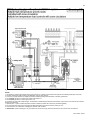
PART 9 – FIELD WIRING .......................................................................................................................................................... 52
A. INSTALLATION MUST COMPLY WITH: .................................................................................................................................. 52
B. FIELD WIRING.......................................................................................................................................................................... 52
C. LINE VOLTAGE WIRING.......................................................................................................................................................... 52
D. THERMOSTAT ......................................................................................................................................................................... 52
PART 10 – FIELD WIRING – VISION 1 OPTION ...................................................................................................................... 55
PART 11 – START-UP PREPARATION.................................................................................................................................... 57
A. CHECK/CONTROL WATER CHEMISTRY ............................................................................................................................... 57
B. FREEZE PROTECTION (WHEN USED) .................................................................................................................................. 58
C. FILL AND TEST WATER SYSTEM .......................................................................................................................................... 58
D. AIR PURGING PROCEDURE FOR HEAT EXCHANGER ........................................................................................................ 58
E. PURGE AIR FROM WATER SYSTEM ..................................................................................................................................... 59
F. CHECK FOR GAS LEAKS ........................................................................................................................................................ 60
LP-171 Rev. 3.3.15
6
G. CHECK THERMOSTAT CIRCUIT(S) ....................................................................................................................................... 60
H. CONDENSATE REMOVAL ...................................................................................................................................................... 60
I. FINAL CHECKS BEFORE STARTING HEATER ....................................................................................................................... 60
PART 12 – START-UP PROCEDURE ....................................................................................................................................... 61
A. OPERATING INSTRUCTIONS ................................................................................................................................................. 61
B. ADJUSTING THE SET POINT .................................................................................................................................................. 61
C. STATUS MENU ........................................................................................................................................................................ 62
D. TEST MODE ............................................................................................................................................................................. 62
PART 13 – START-UP PROCEDURES WITH VISION 1 OPTION ........................................................................................... 62
A. PROGRAMMING THE VISION I OPTION ................................................................................................................................ 63
B. VISION 1 PROGRAM ACCESS ................................................................................................................................................ 63
C. VISION 1 PROGRAM NAVIGATION ........................................................................................................................................ 63
PART 14 – TROUBLESHOOTING ............................................................................................................................................ 65
A. ERROR CODE .......................................................................................................................................................................... 65
B. HEATER ERROR...................................................................................................................................................................... 65
C. HEATER FAULT ....................................................................................................................................................................... 65
PART 15 – MAINTENANCE ...................................................................................................................................................... 67
A. MAINTENANCE PROCEDURES .............................................................................................................................................. 67
B. MAINTENANCE SCHEDULE FOR THE SERVICE TECHNICIAN ........................................................................................... 68
C. COMBUSTION CHAMBER COIL CLEANING INSTRUCTIONS .............................................................................................. 68
D. MAINTENANCE SCHEDULE FOR THE OWNER .................................................................................................................... 69
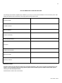
HEATER START-UP REPORT .................................................................................................................................................. 74
MAINTENANCE REPORT ......................................................................................................................................................... 74
MAINTENANCE NOTES ........................................................................................................................................................................................ 78
HTP CUSTOMER INSTALLATION RECORD FORM ............................................................................................................................................. 79
PART 1 – GENERAL SAFETY INFORMATION
A. PRECAUTIONS
This heater is for indoor installations only. Clearance to combustible materials: 0” top, bottom, sides and back. Front must have room
for service, 24” recommended. (A combustible door or removable panel is acceptable front clearance.) This heater has been approved
for closet installation. This heater is designed to be wall mounted. Do not install on the floor. Category IV vent systems only.
INSTALLER – Read all instructions in this manual before installing. Perform steps in the order given.
USER – This manual is for use only by a qualified heating installer/service technician. Refer to user’s information manual for your
reference. Have this heater serviced/inspected by a qualified service technician annually.
FAILURE TO ADHERE TO THE GUIDELINES ON THIS PAGE AND HAVE THIS HEATER SERVICED/INSPECTED ANNUALLY
CAN RESULT IN SUBSTANTIAL PROPERTY DAMAGE, SEVERE PERSONAL INJURY, OR DEATH.
NOTE: When inquiring about service or troubleshooting, reference the model and serial numbers from the heater rating label.
LP-171 Rev. 3.3.15
7
DO NOT USE THIS HEATER IF ANY PART HAS BEEN SUBMERGED IN WATER. Immediately call a qualified service technician.
The heater MUST BE replaced if it has been submerged. Attempting to operate a heater that has been submerged could create
numerous harmful conditions, such as a potential gas leakage causing a fire and/or explosion, or the release of mold, bacteria, or other
harmful particulates into the air. Operating a previously submerged heater could result in property damage, severe personal injury, or
death.
NOTE: Heater damage due to flood or submersion is considered an Act of God, and IS NOT covered under product warranty.
Be sure to disconnect electrical power before opening heater cabinet or performing service. Failure to do so could result in an electrical
shock that could result in property damage, serious personal injury, or death.
NOTE: If the heater is exposed to the following, do not operate until all corrective steps have been made by a qualified serviceman:
1. FIRE
2. DAMAGE
3. WATER
Any claims for damage or shortage in shipment must be filed immediately against the transportation company by the consignee.
Due to the low water content of the heater, improper sizing of the heater with regard to heating system load will result in excessive
cycling and accelerated component failure. HTP DOES NOT warrant failures caused by improperly sized heater applications. DO NOT
oversize the heater to the system. Modular heater installations greatly reduce the likelihood of heater oversizing.
B. IMPROPER COMBUSTION
Do not obstruct combustion and ventilating air flow. Adequate air must be provided for safe operation. Failure to keep the exhaust vent
and intake pipe clear of ice, snow, or other debris could result in property damage, serious personal injury, or death.
C. GAS
Should overheating or gas supply fail to shut off, do not turn off or disconnect electrical supply to circulator. Instead, shut off the gas
supply at a location external to the heater.
D. WHEN SERVICING THE HEATER
To avoid electric shock, disconnect electrical supply before performing
maintenance.
To avoid severe burns, allow heater to cool.
E. HEATER SYSTEM
Do not use petroleum-based cleaning or sealing compounds in a heater
system. Gaskets and seals in the system may be damaged. This can
result in substantial property damage.
Do not use “homemade cures” or “patent medicines”. Substantial
property damage, damage to heater, and/or serious personal injury may
result.
Continual fresh make-up water will reduce heater life. Mineral buildup
reduces heat transfer, overheats the stainless steel heat exchanger, and
causes failure. Addition of oxygen by make-up water can cause internal
corrosion in system components. Leaks in the heater or piping must be
repaired at once.
If you have an old system with cast iron radiators, thoroughly flush the
system (without heater connected) to remove sediment. The high-efficiency heat exchanger can be damaged by build-up or
corrosion due to sediment.
When the heater is used to supply potable water, do not connect it to any heating system or component(s) previously used
with a non-potable water-heating heater.
NOTE: Damages resulting from incorrect installation or from use of products not approved by HTP, Inc. ARE NOT covered by warranty.
F. WATER CHEMISTRY*
Sodium less than 20mGL.
LP-171 Rev. 3.3.15
8
Water pH between 6.0 and 8.0
o Maintain water pH between 6.0 and 8.0. Check with litmus paper or have it chemically analyzed by water treatment
company.
o If the pH differs from above, consult local water treatment company for treatment needed.
Hardness less than 7 grains
o Consult local water treatment companies for unusually hard water areas (above 7 grains hardness).
Chlorine concentration less than 100 ppm
o Using chlorinated fresh water should be acceptable as levels are typically less than 5 ppm.
o Do not connect the heater to directly heat swimming pool or spa water.
o Do not fill heater or operate with water containing chlorine in excess of 100 ppm.
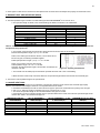
*NOTE: It is recommended to clean heat exchanger at least once a year to prevent lime scale buildup. To clean the heat
exchanger, follow the maintenance procedure in Part 15, Section B of this manual.
Hardness: 7 grains
Chloride levels: 100 ppm
pH levels: 6-8
TDS: 2000 ppm
Sodium: 20 mGL
G. WINTERIZING
NEVER use any toxic chemical, including automotive, standard glycol antifreeze, or ethylene glycol made for hydronic (non-potable)
systems. These chemicals can attack gaskets and seals in heaters, are poisonous if consumed, and can cause injury or death.
Consider piping and installation when determining heater location.
To winterize the heater, drain the entire system. Then apply air pressure to the drain valve and allow air and water to escape from the
purge valve (see piping instructions).
Once you have evacuated as much water as possible, pump non-toxic, NSF food grade propylene glycol, FDA rated as GRAS
(Generally Recognized As Safe), into the system. Consult the glycol manufacturer for specific instructions on concentration percentage
as well as freeze and burst protection methods. Check the volume and concentration of antifreeze to assure protection is adequate to
protect the entire system from freezing. When pumping, allow air and remaining water to escape from purge valve. When the stream
coming out of the purge valve matches the color of the non-toxic glycol, the system is adequately filled.
Finally, it is recommended to start the circulation pump and allow the system to circulate for at 30 minutes to completely blend any
trapped water that might be in the system with the glycol.
PART 2 – BEFORE YOU START
A. WHAT’S IN THE BOX
Also included with the heater:
Temperature and Pressure Relief Valve
Pressure and Temperature Gauge
Intake PVC Tee with Screens
Exhaust PVC Coupling with Screens
Plastic hose and Instructions for Purging Heat Exchanger
Installation Manual
Warranty
B. HOW THE HEATER OPERATES
Modulation Condensing Technology is an intelligent system that delivers highly efficient water heating, while maximizing efficiency
by measuring the data parameters of your system.
Stainless Steel Heat Exchanger
The highly efficient and durable stainless steel heat exchanger is designed to extract the last bit of energy from flue gas before it is
exhausted.
LP-171 Rev. 3.3.15
9
Modulating Combustion System
Modulation during operation is based on supply temperature and desired temperature set point. The set point used for the control
depends upon the programmed central heating curve. The heating curve slope can be changed by the installer to better fit system
needs. The control monitors the system to regulate burner output during operation to match system demand. This increase in efficiency
allows for substantial fuel savings.
Gas Valve
The gas valve senses suction from the blower, allowing gas to flow only if the gas valve is energized and combustion air is flowing.
Swirl Plate System
The gas valve swirl plate controls air and gas flow into the burner, assuring better mixing for improved combustion.
Supply Water Temperature Sensor
This sensor monitors heater output water temperature (system outlet/supply). The control module adjusts the heater firing rate so the
outlet/supply temperature is correct.
Return Water Temperature Sensor
This sensor monitors the return water temperature (system inlet/return). The control module reduces or increases heater input,
depending on how close the inlet/return water temperature is to the outlet water temperature.
Temperature and Pressure Gauge
Allows the user to monitor system temperature and pressure.
Control
The integrated control system monitors inlet/return and outlet/supply water temperature and regulates fan speed to regulate the unit’s
BTU output. This allows the unit to deliver the required amount of heated energy and nothing more.
Flue Pipe Adapter
The flue pipe adapter may be positioned so that the installer is able to find a position that will best facilitate the exhaust and combustion
air pipe connections with the least number of elbows in even the most challenging of situations.
Burner
Constructed of metal fiber and high grade stainless steel, the burner uses pre-mixed air and gas and provides a wide range of firing
rates.
Electrical Field Connections with Terminal Strips
The electrical cover plate allows access to the line voltage and low voltage terminal strips. Attach line voltage conduits to the three
holes at the right of the line voltage terminal strip for power, CH pump and DHW pump. Route low voltage wires through the opening to
the left of the low voltage terminal strip (see Field Wiring Instructions, Part 9).
Condensate Drain Connection
As this is a condensing high efficiency appliance, the unit has a condensate removal system. Condensate is nothing more than water
vapor, derived from combustion products and similar to an automobile when it is initially started. It is very important that the condensate
line slopes away from the heater and down to a suitable inside drain.
If the condensate outlet on the heater is lower than the drain, you must use a condensate removal pump (kit p/n 554200 available from
HTP.) In addition, local authorities may require a condensate neutralizer to neutralize the condensate. Condensate neutralizers are
made up of lime crystals, marble or phosphate chips. Neutralizers can be installed in the field by the installer and purchased from HTP
(p/n N1100).
It is also very important not to expose the condensate line to freezing temperatures or any type of blockage. Plastic tubing must be the
only material used for the condensate line. Steel, brass, copper or other materials will be subject to corrosion or deterioration. A second
vent may be necessary to prevent condensate line vacuum lock on a long horizontal run. Also, an increase in pipe size may be
necessary to allow condensate to drain properly. Support of the condensation line may be necessary to avoid blockage of the
condensate flow.
Spark Ignition
The burner flame is ignited by applying a high voltage to the system spark electrode. This causes a spark from electrode to ground.
The Vision 1 Optional System
By controlling the temperature delivered to the central heating circuits based on outside temperature, the Vision 1 System allows the
installer to take this highly efficient heater and make it even more efficient. The Vision 1 System is also a two temperature system,
using one temperature for central heating and the other for use with an indirect water heater. This allows the user to increase the
temperature supplied to the indirect water heater to get a faster recovery by prioritizing the flow at a higher temperature than may be
needed for the central heating circuits (this requires two separate circulators). You must follow the piping, wiring, and programming
instructions located in the Vision One section of this manual.
LP-171 Rev. 3.3.15
10
C. OPTIONAL EQUIPMENT
Below is a list of optional equipment available from HTP. These additional options may be purchased through your HTP distributor:
Indirect Tank Sensor (Part # 7250P-325)
Outdoor sensor (Part # 7250P-319)
2” Stainless Steel Outside Termination Vent Kit (V500)
3” Stainless Steel Outside Termination Vent Kit (V1000)
2” PVC Concentric Vent Kit (Part # KGAVT0501CVT)
3" PVC Concentric Vent Kit (Part # KGAVT0601CVT)
3” Polypro Vent Kit (Part # 8400P-001)
3” Polypro Pipe (33’ length Part # 8400P-002, 49.5’ length Part # 8400P-003)
Alarm System (Part # 7350P-602) (to monitor any failure)
Condensate Pump (Part # 7250P-320)
Condensate Neutralizer (Part # 554200)
Vision 1 Outdoor Sensing System (Part # 7250P-622)
PART 3 – PREPARE HEATER LOCATION
Carefully consider installation when determining heater location. Please read the entire manual before attempting installation. Failure to
properly take factors such as heater venting, piping, condensate removal, and wiring into account before installation could result in
wasted time, money, and possible property damage and personal injury.
A. BEFORE LOCATING THE HEATER
Incorrect ambient conditions can lead to damage to the heating system and put safe operation at risk. Ensure that the heater installation
location adheres to the information included in this manual. Failure to do so could result in property damage, serious personal injury, or
death.
Failure of heater or components due to incorrect operating conditions IS NOT covered by product warranty.
1. Installation Area (Mechanical Room) Operating Conditions
o
o
o
o
Ensure ambient temperatures are higher than 32 F/0 C and lower than 104 F/40 C.
Prevent the air from becoming contaminated by the products, places, and conditions listed in this manual, Part 3, Section F.
Avoid continuously high levels of humidity
Never close existing ventilation openings
The service life of the heater’s exposed metallic surfaces, such as the casing, as well as internal surfaces, such as the heat exchanger,
are directly influenced by proximity to damp and salty marine environments. In such areas, higher concentration levels of chlorides from
sea spray coupled with relative humidity can lead to degradation of the heat exchanger and other heater components. In these
environments, heaters must not be installed using direct vent systems which draw outdoor air for combustion. Such heaters must be
installed using room air for combustion. Indoor air will have a much lower relative humidity and, hence, potential corrosion will be
minimized.
This heater is certified for indoor installations only. Do not install the heater outdoors. Failure to install this heater indoors could result in
substantial property damage, severe personal injury, or death.
2. Check for nearby connections to:
System water piping
Venting connections
Gas supply piping
Electrical power
Condensate drain
3. Check area around heater. Remove any combustible materials, gasoline, and other flammable liquids.
LP-171 Rev. 3.3.15
11
Failure to keep heater area clear and free of combustible materials, liquids, and vapors can result in substantial property damage,
severe personal injury, or death.
4. Gas control system components must be protected from dripping water during operation and service.
5. If the heater is to replace an existing heater, check for and correct any existing system problems, such as:
System leaks
Location that could cause the system and heater to freeze and leak.
Incorrectly-sized expansion tank
6. Clean and flush system when reinstalling a heater.
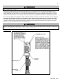
NOTE: When installing in a zero clearance location, it may not be possible to read or view some product labeling. It is recommended to
make note of the heater model and serial number.
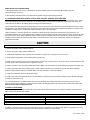
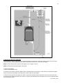
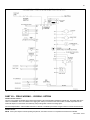
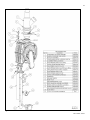
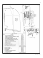
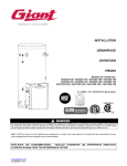
Figure 1 –Specifications – LP-171-B
Before considering location, many factors need to be addressed. Piping, Venting, and Condensation Removal are just a few of the
issues that need attention prior to the installation of the heater. Please read the entire manual, as it could save time and money.
B. LEVELING
In order for the condensate to properly flow out of the collection system, the heater must be installed level. The location must also
support the heater when it is full of water.
LP-171 Rev. 3.3.15
12
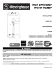
C. CLEARANCES FOR SERVICE ACCESS
See Figure 2 for recommended service clearances. If you do not provide the minimum clearances shown, it may not be possible to
service the heater without removing it from the space.
Figure 2 – Required Clearances
Space must be provided with combustion/ventilation air openings correctly sized for all other appliances located in the same space as
the heater. The heater cover must be securely fastened to prevent the heater from drawing air form the heater room. This is particularly
important if the heater is in a room with other appliances. Failure to comply with the above warnings could result in substantial property
damage, severe personal injury, or death.
D. RESIDENTIAL GARAGE, CLOSET, AND ALCOVE INSTALLATIONS
Check with your local Authority Having Jurisdiction for requirements when installing heater in a garage, closet, or alcove. Please read
the entire manual before attempting installation. Failure to properly take factors such as heater venting, piping, condensate removal,
and wiring into account before installation could result in wasted time, money, and possible property damage and personal injury.
PRECAUTIONS
If the heater is located in a residential garage, per ANSI Z223.1:
Mount the bottom of the heater a minimum of 18” above the floor of the garage, to ensure the burner and ignition devices are
well off the floor.
Locate or protect the heater so it cannot be damaged by a moving vehicle.
For closet or alcove installations, a two pipe venting system must be used. Failure to follow this warning could result in substantial
property damage, severe personal injury, or death.
The space must be provided with correctly sized combustion/ventilation air openings for all other heaters located in the space with the
heater. Do not install the heater in an attic. Failure to comply with these warnings could result in substantial property damage, severe
personal injury, or death.
NOTE: For installations using room air for combustion, refer to the heater venting section, Part 6 in this manual.
E. EXHAUST VENT AND INTAKE PIPE
The appliance is rated ANSI Z21.13 Category IV (pressurized vent, likely to form condensate in the vent) and requires a special vent
system designed for pressurized venting.
NOTE: The venting options described here (and further detailed in the Venting section of this manual) are the lone venting
options approved for this appliance. Failure to vent the appliance in accordance with the provided venting instructions will
void the warranty.
LP-171 Rev. 3.3.15
13
Failure to vent the appliance properly will result in serious personal injury or death.
Vents must be properly supported. Appliance exhaust and intake connections are not designed to carry heavy weight. Vent support
brackets must be within 1’ of the appliance and the balance at 4’ intervals. Appliance must be readily accessible for visual inspection for
the first 3’ from the appliance.
DIRECT VENT INSTALLATION OF EXHAUST VENT AND INTAKE PIPE
When installing a direct vent, combustion air must be drawn from the outdoors directly into the appliance intake, and exhaust must
terminate outside. There are two basic direct vent options detailed in this manual: 1. Side Wall Venting and 2. Roof Venting.
Be sure to locate the appliance such that the exhaust vent and intake piping can be routed through the building and properly
terminated. Different vent terminals can be used to simplify and eliminate multiple penetrations in the building structure (see Optional
Equipment in Venting Section). The exhaust vent and intake piping lengths, routing and termination methods must all comply with the
methods and limits given in the Venting section of this manual.
When installing a combustion air intake from outdoors, care must be taken to utilize uncontaminated combustion air. NOTE: To
prevent combustion air contamination, see Table 1.
Do not attempt to vent this appliance by any means other than those described in this manual. Doing so will void the warranty, and may
result in severe personal injury or death.
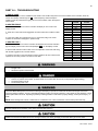
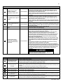
F. PREVENT COMBUSTION AIR CONTAMINATION
Install intake air piping for the heater as described in the Venting section. Do not terminate exhaust in locations that can allow
contamination of intake air.
PRODUCTS TO AVOID
Spray cans containing fluorocarbons
Permanent wave solutions
Chlorinated waxes/cleaners
Chlorine-based swimming pool chemicals
Calcium chloride used for thawing
Sodium chloride used for water softening
Refrigerant leaks
Paint or varnish removers
Hydrochloric or Muriatic acid
Cements and glues
Antistatic fabric softeners used in clothes dryers
Chlorine-type bleaches, laundry detergents, and cleaning solvents
Adhesives used to fasten building products
Table 1 - Contaminant Table
AREAS LIKELY TO HAVE CONTAMINANTS
Dry cleaning/laundry areas and establishments
Swimming pools
Metal fabrication plants
Beauty shops
Refrigeration repair shops
Photo processing plants
Auto body shops
Plastic manufacturing plants
Furniture refinishing areas and establishments
New building construction
Remodeling areas
Garages and workshops
You must pipe outside air to the heater air intake. Ensure that the intake air will not contain any of the contaminants listed in Table 1.
For example, do not pipe intake near a swimming pool. Also, avoid areas subject to exhaust fumes from laundry facilities. These areas
always contain contaminants. Contaminated air will damage the heater, resulting in possible substantial property damage, severe
personal injury, or death.
NOTE: DAMAGE TO THE HEATER CAUSED BY EXPOSURE TO CORROSIVE VAPORS IS NOT COVERED BY WARRANTY.
(Refer to the limited warranty for complete terms and conditions).
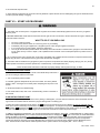
G. REMOVING AN EXISTING HEATER FROM AN EXISTING COMMON VENT SYSTEM
Do not install the heater into a common vent with any other appliance. This will cause flue gas spillage or appliance malfunction,
resulting in possible substantial property damage, severe personal injury, or death.
LP-171 Rev. 3.3.15
14
Failure to follow all instructions can result in flue gas spillage and carbon monoxide emissions, causing severe personal injury or death.
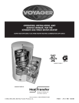
When removing an existing heater, follow the steps below with each appliance remaining connected to the common venting system in
operation, while other appliances remaining connected to common venting system are not operating.
1. Seal any unused openings in the common venting system.
2. Visually inspect the venting system for proper size and horizontal pitch to
determine if there is blockage, leakage, corrosion or other deficiencies that could
cause an unsafe condition.
3. If practical, close all building doors, windows and all doors between the space
in which the appliance remains connected to the common venting system located
and other spaces in the building. Turn on clothes dryers and any appliances not
connected to the common venting system. Turn on any exhaust fans, such as
range hoods and bathroom exhausts, at maximum speed. Do not operate a
summer exhaust fan. Close all fireplace dampers.
4. Place in operation the appliance being inspected. Follow the lighting
instructions. Adjust the thermostat so the appliance will operate continuously.
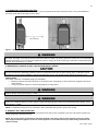
5. Test for spillage at the draft hood relief opening after 5 minutes of main burner
operation. Use the flame of a match or candle or smoke from a cigarette.
Figure 3
6. After it has been determined that each appliance remaining connected to
common venting system properly vents when tested as outlined, return doors, windows, exhaust fans, fireplace dampers and any other
gas burning appliance to their previous condition of use.
7. Any improper operation of the common venting system should be corrected to conform to the National Fuel Gas Code, ANSI Z223.1.
When resizing any portion of the common venting system, the system should approach the minimum size as determined using the
appropriate tables in Appendix G in the National Fuel Gas Code, ANSI Z 223.1.
PART 4 – PREPARE HEATER
UNCRATING HEATER – Any claims for damage or shortage in shipment must be filed immediately against the transportation company
by the consignee.
o
COLD WEATHER HANDLING – If the heater has been stored in a very cold location (BELOW 0 F) before installation, handle with care
until the plastic components come to room temperature.
A. REMOVE HEATER FROM BOX
The heater is easy to handle. Care must be taken to place it in a safe location prior to installation to prevent damage to the bottom
mechanical connections.
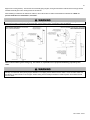
B. WALL MOUNTING CONSIDERATIONS
These heaters are wall mounted. Use only the wall mounting instructions included in installation envelope.
The wall must be capable of carrying the weight of the heater and its related components. The weights of the heaters are
approximately:
MC-50 – 71 lbs MC-80 – 74 lbs
MC-99 – 84 lbs MC-120 – 84 lbs
Failure to comply with above could result in substantial property damage, severe personal injury, or death.
LP-171 Rev. 3.3.15
15
C. WALL MOUNTING INSTRUCTIONS
This heater is heavy and awkward to lift. It is recommended and safer to install the heater with two people. Use caution as to not drop
the heater, which could damage the heater and cause property damage and/or personal injury. Verify that the heater is securely
mounted before leaving unsupervised. Failure to comply with the above and properly mount the heater could result in substantial
property damage, severe personal injury, or death.
The wall must be vertically plumb and capable of carrying the weight of the heater and its related components.
The building frame (studs) must be 16" on center. If not, you must use 1/2" minimum plywood 24" x 48", fastened with at least (14) #12
x 3" (3/16" x 3") round head tapping screws to the frame of the building to provide proper support for the heater. Alternate methods of
mounting must not be used. (ex. toggle bolts, hollow wall anchors) or any other fastener other than #12 x 3" (3/16" x 3") round head
tapping screws.
If the heater is not vertically plumb, improper and unsatisfactory operation may occur, causing excessive condensation build-up,
nuisance fault codes, and unnecessary maintenance.
D. INSTALLATION STEPS
1. Prior to lifting the heater onto the wall, use the enclosed template to level and locate the 2 primary (#12 x 3" [3/16" x 3"]) round head
tapping screws, leaving about 1/4" between the screw head and the wall surface to allow for access to the keyway slot located in the
back of the heater panel. It is extremely important that the line on the template is level when locating the first 2 screws. Failure to do so
will result in an uneven or out of level installation.
2. Remove the heater cover. Locate the 2 keyway slots over the screws. Then lower the heater onto the smallest part of the keyway
slot.
3. Once the heater is mounted on the first 2 screws, finish tightening the screws to the back panel. Then install the 6 additional screws
of the same size to the back panel holes. This will provide additional strength and support to the heater.
PART 5 – HEATER PIPING
Failure to follow the instructions in this section WILL VOID the warranty and may result in property damage, serious injury, or death.
Never use dielectric unions or galvanized steel fittings when connecting to a stainless steel storage tank or heater. Use only copper or
brass fittings. Teflon thread sealant must be used on all connections. All piping and components connected to the heater must be
approved for potable water systems.
Plumbing of this product should only be done by a qualified, licensed plumber in accordance with all local plumbing codes. The heater
may be connected to a storage tank to supply domestic hot water. HTP offers 60/80/119/175 gallon size storage tanks in either
stainless steel or glass-lined construction. These storage tanks can be directly connected to the heater supply and return connection.
The National Standard Plumbing Code, the National Plumbing Code of Canada, and the Uniform Plumbing Code limit the pressure of
the heat transfer fluid to less than the minimum working pressure of the potable water system up to 30 psi maximum. The heat transfer
th
fluid must be water or other non-toxic fluid having a toxicity of Class 1, as listed in Clinical Toxicology of Commercial Products, 5
Edition.
A. GENERAL PIPING INFORMATION
The building piping system must meet or exceed the piping requirements in this manual.
Use two wrenches when tightening water piping at heater. Use one wrench to prevent the heater return or supply line from turning.
Failure to prevent piping connections from turning could cause damage to heater components.
LP-171 Rev. 3.3.15
16
1. The water supply should be shut off while connecting the heater. A manual control valve must be placed on the inlet connection to
the heater. Unions can be used on both the hot and cold water lines for future servicing and disconnection of the unit.
2. Purge the water line to remove all debris and air. Debris will damage the water heater.
3. If the heater is to be used as a potable water source, it must not be connected to a system that was previously used for non-potable
purposes.
4. Ensure that the water filter on the heater is clean and installed.
5. New plumbing typically has contamination in the lines. Please flush the system before connection.
The heater control module uses temperature sensors to provide both high limit protection and modulating temperature control. The
control module also provides low water protection by sensing the water pressure. Some codes/jurisdictions may require additional
external controls.
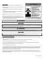
B. RELIEF VALVE
The relief valve must comply with the standard for Relief Valves and Automatic Gas Shutoff Devices for Hot Water Supply Systems
(ANSI Z21.22) and/or the standard Temperature, Pressure, Temperature and Pressure Relief Valves and Vacuum Relief Valves,
CAN1-4.4, as well as all local codes. In addition, the relief valve must be rated to the maximum BTU/hr rating of the heater.
The American National Standard (ANSI Z21.10.3) / Canadian Standard (CSA 4.3) do not require a combination temperature and
pressure relief valve for this heater. However, a combination temperature and pressure relief valve may be required by local codes.
Connect discharge piping to safe disposal location. See the following guidelines.
To avoid water damage or scalding due to relief valve operation:
Discharge line must be connected to relief valve outlet and run to a safe place of disposal. Terminate the discharge line in a
manner that will prevent possibility of severe burns or property damage should the relief valve discharge.
Discharge line must be as short as possible and the same size as the valve discharge connection throughout its entire length.
Discharge line must pitch downward from the valve and terminate at least 6” above the floor drain, making discharge clearly
visible.
o
The discharge line shall terminate plain, not threaded, with a material serviceable for temperatures of 375 F or greater.
Do not pipe discharge to any location where freezing could occur.
No shutoff valve may be installed between the relief valve and heater or in the discharge line. Do not plug or place any
obstruction in the discharge line.
Test the operation of the relief valve after filling and pressurizing the system by lifting the lever. Make sure the valve
discharges freely. If the valve fails to operate correctly, immediately replace with a new properly rated relief valve.
Test relief valve at least once annually to ensure the waterway is clear. If valve does not operate, turn the heater “off” and call
a plumber immediately.
Take care whenever operating relief valve to avoid scalding injury or property damage.
For heaters installed with only a pressure relief valve, the separate storage vessel must have a temperature and pressure
relief valve installed. This relief valve shall comply with Relief Valves for Hot Water Supply Systems, ANSI Z21.22 / CSA4.4.
FAILURE TO COMPLY WITH THE ABOVE GUIDELINES COULD RESULT IN FAILURE OF RELIEF VALVE OPERATION,
RESULTING IN POSSIBILITY OF SUBSTANTIAL PROPERTY DAMAGE, SEVERE PERSONAL INJURY, OR DEATH.
Hot water outlet pipes can be hot to touch. Insulation must be used for hot water pipes below 36” to protect children against injuries due
to scalds.
NOTE: If a relief valve discharges periodically, this may
be due to thermal expansion in a closed water supply
system. DO NOT PLUG THE RELIEF VALVE. An
expansion tank may be required.
APPROXIMATE TIME / TEMPERATURE RELATIONSHIPS IN SCALDS
o
120 F
More than 5 minutes
o
125 F
1 ½ to 2 minutes
o
130 F
About 30 seconds
o
135 F
About 10 seconds
o
140 F
Less than 5 seconds
o
145 F
Less than 3 seconds
o
150 F
About 1 ½ seconds
o
155 F
About 1 second
Table 2
LP-171 Rev. 3.3.15
17
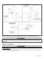
C. SEPARATE LOW WATER CUTOFF
A low water cutoff may be required by state and local codes, or by some insurance companies. A low water cutoff is also required if the
heater is installed above the piping level. Check code requirements before installing the heater.
If required:
Use an electrode probe type low water cutoff designed for hydronic installations.
Install in a tee on the supply piping above the heater.
Follow low water cutoff manufacturer’s instructions.
D. BACKFLOW PREVENTER
Use a backflow preventer specifically designed for hydronic heater installations. This valve should be installed on the cold water fill
supply line per local codes. (See piping details at the end of this section.)
All piping methods shown in this manual use primary/secondary connection to the heater loop. This is to avoid the possibility of noise or
actuator problems in zone valves because of the high-head heater circulator. For other piping methods, consult your local HTP
representative or refer to separate piping details in this manual.
E. SYSTEM WATER PIPING METHODS
EXPANSION TANK AND MAKE-UP WATER
1. Ensure expansion tank size will handle heater and system water volume and temperature. Allow 3 gallons for the heater and its
piping.
Expansion tanks must be sized according to total system volume. This includes all length of pipe, all fixtures, appliances, etc. Failure to
properly size system expansion could result in wasted time, money, and possible property damage, personal injury, or death.
Undersized expansion tanks cause system water to be lost from relief valve and make-up water to be added through fill valve. Eventual
failure can result due to excessive make-up water addition. SUCH FAILURE IS NOT COVERED BY WARRANTY.
2. Expansion tank must be located as shown in Piping diagrams, or following recognized design methods. See tank manufacturer’s
instructions for details.
3. Connect the expansion tank to the air separator only if the separator is on the suction side of the circulator. Always install the system
fill connection at the same point as the expansion tank connection to the system.
4. Most chilled water systems are piped using a closed type expansion tank.
DO NOT install automatic air vents on closed-type expansion tank systems. Air must remain in the system and return to the tank to
provide its air cushion. An automatic air vent would cause air to leave the system, resulting in water-logging the expansion tank.
DIAPHRAGM (OR BLADDER) EXPANSION TANK
Always install an automatic air vent on top of the air separator to remove residual air from the system.
F. CIRCULATORS
DO NOT use the heater circulator in any location other than the ones shown in this manual. The heater circulator is selected to ensure
adequate flow through the heater. Failure to do so could result in unreliable performance and nuisance shutdowns from insufficient flow.
LP-171 Rev. 3.3.15
18
SIZING SPACE HEAT SYSTEM PIPING
1. See Piping Details in this section. In all diagrams, the space heating system is isolated from the heating loop by the
primary/secondary connection.
2. Size the piping and components in the space heating system using recognized design methods.
G. HYDRONIC PIPING WITH CIRCULATORS, ZONE VALVES, AND MULTIPLE HEATERS
This heater may function in a closed loop 15 psi system. An optional water pressure switch ensures adequate pressure in the system.
The heater will not operate without a minimum of 10 psi water pressure. This assures you that if the system does have a leak, the
heater will lock out (PRO on the display) before it damages the heat exchanger.
The included temperature and pressure gauge allows the user to monitor the system pressure and outlet temperature from the heater.
It is important to note that the heater has a minimal amount of pressure drop that must be calculated when sizing the circulators. Each
installation must also have an air elimination device that will remove air from the system.
Observe minimum 1” clearance around all un-insulated hot water pipes when openings around pipes are not protected by noncombustible materials. On a heater installed above radiation level, some states and local codes require a low water cut off device (See
Part C this section). If the heater supplies hot water to heating coils in air handler units, flow control valves or other devices must be
installed to prevent gravity circulation of heater water in the coils during the cooling cycle. Chilled water medium must be piped in
parallel with the heater.
The heater should not be operated as a potable hot water heater. Operating this heater as a potable water heater will VOID warranty.
1. Connect the system return marked “Heater In”.
2. Connect the system supply marked “Heater Out”.
3. Install purge and balance valve or shut off valve and drain on system return to purge air out of each zone.
4. Install a back flow preventer on the cold feed make-up water line.
5. Install a pressure reducing valve on the cold feed make-up water line, (15 psi nominal on the system return). Check temperature and
pressure gauge, which should read minimum pressure of 12 psi.
6. Install a circulator as shown in piping details (this section). Make sure the circulator is properly sized for the system and friction loss.
7. Install an expansion tank on the system supply. Consult the tank manufacturer’s instruction for specific information relating to
expansion tank installation. Size the expansion tank for the required system volume and capacity.
8. Install an air elimination device on the system supply.
9. Install a drain valve at the lowest point of the system. NOTE: The heater cannot be drained completely of water without purging the
unit with an air pressure 15 psi.
10. The safety relief valve is installed at the factory. Pipe the discharge of the safety relief valve to prevent injury in the event of
pressure relief. Pipe the discharge 6” above the drain to a drain. Provide piping that is the same size as the safety relief valve outlet.
Never block the outlet of safety relief valve.
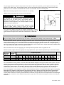
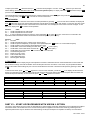
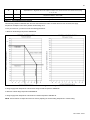
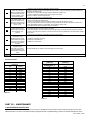
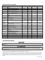
H. CIRCULATOR SIZING
The heat exchanger has a minimum total water volume that must be taken into account when sizing the circulator. These minimum
water volumes are listed in Table 3 below.
MINIMUM BOILER FLOW RATES
MODEL
MC-50
MC-80
MC-99
MC-120
Table 3 – Minimum Heat Exchanger Water Volumes
MINIMUM FLOW (GPM)
3.3
5.3
7.8
8
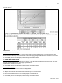
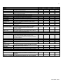
In addition, the heat exchanger has pressure drop which must be considered in your system design. Refer to the graph in Figure 4 for
pressure drop through the heat exchanger for recommended pump selection at a 20∆t design.
LP-171 Rev. 3.3.15
19
The chart below represents various system temperatures and their respective flows and friction loss through the heater, which will aid
circulator selection.
Figure 4 – Pressure Drop Graph and Temperature Rise Chart – LP-171-F NOTE: The recommended circulators are based on 1 gpm per 10,000
btu/hr with 20∆t.
I. ZONING WITH ZONE VALVES
1. Connect heater to system as shown in 1A and 1B in Piping Details when zoning with zone valves. The primary/secondary piping
shown ensures the heater loop will have sufficient flow. It also avoids applying the high head of the heater circulator to the zone valves.
2. Connect DHW (domestic hot water) piping to indirect storage water heater as shown.
J. ZONING WITH CIRCULATORS
1. Connect heater to system when circulator zoning as shown in 1C and 1D in Piping Details when zoning with circulators. The heater
circulator cannot be used for a zone. It must supply only the heater loop.
Install a separate circulator for each zone.
2. Connect DHW (domestic hot water) piping to indirect storage water heater as shown.
K. MULTIPLE HEATERS
1. Connect multiple heaters as shown in 1E and 1F in Piping Details.
2. All piping shown is reverse return to assure balanced flow through the connected heaters.
3. Each connected heater must have its own circulator pump to assure adequate flow.
4. Connect DHW (domestic hot water) piping to indirect storage water heater as shown.
LP-171 Rev. 3.3.15
20
L. FILL AND PURGE HEATING SYSTEM
Attach the hose to balance and purge hose connector or drain valve and run hose to nearest drain.
Close the other side of the balance and purge valve or the shut off valve after the drain.
Open first zone balance and purge or drain valve to let water flow out the hose. If zone valves are used, open the valves one
at a time manually. (NOTE: You should check valve manufacturer’s instruction prior to opening valves manually, so as not to
damage the valve.)
Manually operate fill valve regulator. When water runs out of the hose, while it’s connected to the balance and purge valve or
drain you will see a steady stream of water (without bubbles). Close balance and purge valve or drain to stop the water from
flowing. Disconnect the hose and connect it to next zone to be purged.
Repeat this procedure for additional zones (one at time).
For installations that incorporate standing iron radiation and systems with manual vents at the highest points: Follow the
above section and, starting with the nearest manual vent, open until water flows out. Then close vent. Repeat procedure, working your
way toward furthest air vent. It may be necessary to install a basket strainer in an older system where larger amounts of sediment may
be present. Annual cleaning of the strainer may be necessary.
Upon completion, make sure that the fill valve is in automatic position and each zone balance and purge or shut off is in an open
position and zone valves are positioned for automatic operation.
Use only inhibited propylene glycol solutions, specially formulated for hydronic systems. Ethylene glycol is toxic and can attack gaskets
and seals used in hydronic systems. Glycol mixtures should not exceed 50%.
1. Glycol for hydronic applications includes inhibitors that prevent it from attacking metallic system components. Make certain that the
system fluid is checked for the correct glycol concentration and inhibitor level.
2. The glycol solution should be tested at least once a year and as recommended by the glycol manufacturer.
3. Anti-freeze solutions expand more than water. For example a 50% by volume solution expands 4.8% in volume for a temperature
increase from 32° F to 180° F, while water expands 3% with the same temperature rise. Allowances must be made for this expansion in
the system design.
4. A 30% mixture of glycol will result in 15% BTU output loss and a 5% increase in head against system circulator.
5. A 50% mixture of glycol will result in 30% BTU output loss and a 50% increase in head against system circulator.
It is highly recommended that you carefully follow the glycol manufacturer’s concentrations, expansion requirements, and maintenance
recommendations (pH additive breakdown, inhibitor reduction, etc.) You must carefully figure the additional system friction loss, as well
as the reduction in heat transfer coefficients.
LP-171 Rev. 3.3.15
21
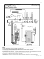
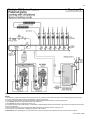
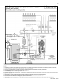
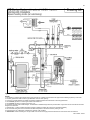
M. PIPING DETAILS
Figure 5
LP-171 Rev. 3.3.15
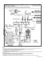
22
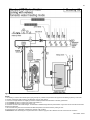
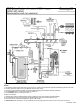
Figure 6
NOTES:
1. This drawing is meant to demonstrate system piping concept only. Installer is responsible for all equipment and detailing required by local codes.
2. All closely spaced tees shall be within 4 pipe diameters center to center spacing.
3. A minimum of 6 pipe diameters of straight pipe shall be installed upstream and downstream of all closely spaced tees.
4. The minimum pipe size for connecting an indirect water heater is 1”.
5. The minimum pipe size for connecting the unit is 1.25”.
6. Circulators are shown with isolation flanges. The alternative is standard flanges with full port ball valves. Purge valves can be used with the circulator
flanges as an alternative.
7. The anti-scald mixing valve is recommended if the DHW temperature is set above the factory setting of 119 oF.
8. Install a minimum of 12 diameters of straight pipe upstream of all circulators.
9. Winterization: When winterizing the unit, put a drain valve on both the supply and return between the union and the shut-off connection.
LP-171 Rev. 3.3.15
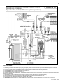
23
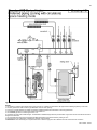
Figure 7
NOTES:
1. This drawing is meant to demonstrate system piping concept only. Installer is responsible for all equipment and detailing required by local codes.
2. All closely spaced tees shall be within 4 pipe diameters center to center spacing.
3. A minimum of 6 pipe diameters of straight pipe shall be installed upstream and downstream of all closely spaced tees.
4. The minimum pipe size for connecting an indirect water heater is 1”.
5. The minimum pipe size for connecting the unit is 1.25”.
6. Circulators are shown with isolation flanges. The alternative is standard flanges with full port ball valves. Purge valves can be used with the circulator
flanges as an alternative.
7. The anti-scald mixing valve is recommended if the DHW temperature is set above the factory setting of 119 oF.
8. Install a minimum of 12 diameters of straight pipe upstream of all circulators.
9. Winterization: When winterizing the unit, put a drain valve on both the supply and return between the union and the shut-off connection.
LP-171 Rev. 3.3.15
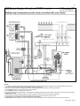
24
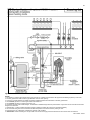
Figure 8
NOTES:
1. This drawing is meant to demonstrate system piping concept only. Installer is responsible for all equipment and detailing required by local codes.
2. All closely spaced tees shall be within 4 pipe diameters center to center spacing.
3. A minimum of 6 pipe diameters of straight pipe shall be installed upstream and downstream of all closely spaced tees.
4. The minimum pipe size for connecting an indirect water heater is 1”.
5. The minimum pipe size for connecting the unit is 1.25”.
6. Circulators are shown with isolation flanges. The alternative is standard flanges with full port ball valves. Purge valves can be used with the circulator
flanges as an alternative.
7. The anti-scald mixing valve is recommended if the DHW temperature is set above the factory setting of 119 oF.
8. Install a minimum of 12 diameters of straight pipe upstream of all circulators.
9. Winterization: When winterizing the unit, put a drain valve on both the supply and return between the union and the shut-off connection.
LP-171 Rev. 3.3.15
25
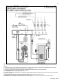
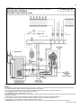
Figure 9
NOTES:
1. This drawing is meant to demonstrate system piping concept only. Installer is responsible for all equipment and detailing required by local codes.
2. All closely spaced tees shall be within 4 pipe diameters center to center spacing.
3. A minimum of 6 pipe diameters of straight pipe shall be installed upstream and downstream of all closely spaced tees.
4. The minimum pipe size for connecting an indirect water heater is 1”.
5. The minimum pipe size for connecting the unit is 1.25”.
6. Circulators are shown with isolation flanges. The alternative is standard flanges with full port ball valves. Purge valves can be used with the circulator
flanges as an alternative.
7. The anti-scald mixing valve is recommended if the DHW temperature is set above the factory setting of 119 oF.
8. Install a minimum of 12 diameters of straight pipe upstream of all circulators.
9. Winterization: When winterizing the unit, put a drain valve on both the supply and return between the union and the shut-off connection.
LP-171 Rev. 3.3.15
26
Figure 10
NOTES:
1. This drawing is meant to demonstrate system piping concept only. Installer is responsible for all equipment and detailing required by local codes.
2. All closely spaced tees shall be within 4 pipe diameters center to center spacing.
3. A minimum of 6 pipe diameters of straight pipe shall be installed upstream and downstream of all closely spaced tees.
4. The minimum pipe size for connecting an indirect water heater is 1”.
5. The minimum pipe size for connecting the unit is 1.25”.
6. Circulators are shown with isolation flanges. The alternative is standard flanges with full port ball valves. Purge valves can be used with the circulator
flanges as an alternative.
7. The anti-scald mixing valve is recommended if the DHW temperature is set above the factory setting of 119 oF.
8. Install a minimum of 12 diameters of straight pipe upstream of all circulators.
9. Winterization: When winterizing the unit, put a drain valve on both the supply and return between the union and the shut-off connection.
LP-171 Rev. 3.3.15
27
Figure 11
NOTES:
1. This drawing is meant to demonstrate system piping concept only. Installer is responsible for all equipment and detailing required by local codes.
2. All closely spaced tees shall be within 4 pipe diameters center to center spacing.
3. A minimum of 6 pipe diameters of straight pipe shall be installed upstream and downstream of all closely spaced tees.
4. The minimum pipe size for connecting an indirect water heater is 1”.
5. The minimum pipe size for connecting the unit is 1.25”.
6. Circulators are shown with isolation flanges. The alternative is standard flanges with full port ball valves. Purge valves can be used with the circulator
flanges as an alternative.
7. The anti-scald mixing valve is recommended if the DHW temperature is set above the factory setting of 119oF.
8. Install a minimum of 12 diameters of straight pipe upstream of all circulators.
9. Winterization: When winterizing the unit, put a drain valve on both the supply and return between the union and the shut-off connection.
LP-171 Rev. 3.3.15
28
PART 6 – PIPING WITH OPTIONAL VISION 1 SYSTEM
(DHW PRIORITY WITH OUTDOOR RESET)
A. VISION 1 SYSTEM PIPING
It is important that the system piping is done correctly when using the Vision 1 System. Follow the piping diagrams 2A through 3G when
piping your heater. All general piping practices should still be maintained.
B. ZONING WITH ZONE VALVES USING VISION 1
1. Connect the heater to the system as shown in piping details 2A through 2C.
2. Connect the DHW circulator (P2) directly to the heater as shown in the piping details. The heater circulator (P1) will shut down when
there is a DHW demand.
C. ZONING WITH CIRCULATORS USING VISION 1
1. Connect the heater to the system as shown in piping details 3A through 3G.
2. Connect the DHW circulator (P2) directly to the heater as shown in the piping details. The heater circulator (P1) will shut down when
there is a DHW demand.
LP-171 Rev. 3.3.15
29
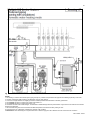
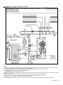
D. PIPING DETAILS WITH THE VISION 1 SYSTEM
Figure 12
NOTES:
1. This drawing is meant to demonstrate system piping concept only. Installer is responsible for all equipment and detailing required by local codes.
2. All closely spaced tees shall be within 4 pipe diameters center to center spacing.
3. A minimum of 6 pipe diameters of straight pipe shall be installed upstream and downstream of all closely spaced tees.
4. The minimum pipe size for connecting an indirect water heater is 1”.
5. The minimum pipe size for connecting the unit is 1.25”.
6. Circulators are shown with isolation flanges. The alternative is standard flanges with full port ball valves. Purge valves can be used with the circulator
flanges as an alternative.
7. Optional Vision 1 system includes temperature sensors for DHW and outdoor air and must be purchased separately.
8. The anti-scald mixing valve is recommended if the DHW temperature is set above the factory setting of 119 oF.
9. Install a minimum of 12 diameters of straight pipe upstream of all circulators.
10. Winterization: When winterizing the unit, put a drain valve on both the supply and return between the union and the shut-off connection.
LP-171 Rev. 3.3.15
30
Figure 13
NOTES:
1. This drawing is meant to demonstrate system piping concept only. Installer is responsible for all equipment and detailing required by local codes.
2. All closely spaced tees shall be within 4 pipe diameters center to center spacing.
3. A minimum of 6 pipe diameters of straight pipe shall be installed upstream and downstream of all closely spaced tees.
4. The minimum pipe size for connecting an indirect water heater is 1”.
5. The minimum pipe size for connecting the unit is 1.25”.
6. Circulators are shown with isolation flanges. The alternative is standard flanges with full port ball valves. Purge valves can be used with the circulator
flanges as an alternative.
7. Optional Vision 1 system includes temperature sensors for DHW and outdoor air and must be purchased separately.
8. The anti-scald mixing valve is recommended if the DHW temperature is set above the factory setting of 119 oF.
9. Install a minimum of 12 diameters of straight pipe upstream of all circulators.
10. Winterization: When winterizing the unit, put a drain valve on both the supply and return between the union and the shut-off connection.
LP-171 Rev. 3.3.15
31
Figure 14
NOTES:
1. This drawing is meant to demonstrate system piping concept only. Installer is responsible for all equipment and detailing required by local codes.
2. All closely spaced tees shall be within 4 pipe diameters center to center spacing.
3. A minimum of 6 pipe diameters of straight pipe shall be installed upstream and downstream of all closely spaced tees.
4. The minimum pipe size for connecting an indirect water heater is 1”.
5. The minimum pipe size for connecting the unit is 1.25”.
6. Circulators are shown with isolation flanges. The alternative is standard flanges with full port ball valves. Purge valves can be used with the circulator
flanges as an alternative.
7. Optional Vision 1 system includes temperature sensors for DHW and outdoor air and must be purchased separately.
8. The anti-scald mixing valve is recommended if the DHW temperature is set above the factory setting of 119 oF.
9. Install a minimum of 12 diameters of straight pipe upstream of all circulators.
10. Winterization: When winterizing the unit, put a drain valve on both the supply and return between the union and the shut-off connection.
LP-171 Rev. 3.3.15
32
Figure 15
NOTES:
1. This drawing is meant to demonstrate system piping concept only. Installer is responsible for all equipment and detailing required by local codes.
2. All closely spaced tees shall be within 4 pipe diameters center to center spacing.
3. A minimum of 6 pipe diameters of straight pipe shall be installed upstream and downstream of all closely spaced tees.
4. The minimum pipe size for connecting an indirect water heater is 1”.
5. The minimum pipe size for connecting the unit is 1.25”.
6. Circulators are shown with isolation flanges. The alternative is standard flanges with full port ball valves. Purge valves can be used with the circulator
flanges as an alternative.
7. Optional Vision 1 system includes temperature sensors for DHW and outdoor air and must be purchased separately.
8. The anti-scald mixing valve is recommended if the DHW temperature is set above the factory setting of 119oF.
9. Install a minimum of 12 diameters of straight pipe upstream of all circulators.
10. Winterization: When winterizing the unit, put a drain valve on both the supply and return between the union and the shut-off connection.
LP-171 Rev. 3.3.15
33
Figure 16
NOTES:
1. This drawing is meant to demonstrate system piping concept only. Installer is responsible for all equipment and detailing required by local codes.
2. All closely spaced tees shall be within 4 pipe diameters center to center spacing.
3. A minimum of 6 pipe diameters of straight pipe shall be installed upstream and downstream of all closely spaced tees.
4. The minimum pipe size for connecting an indirect water heater is 1”.
5. The minimum pipe size for connecting the unit is 1.25”.
6. Circulators are shown with isolation flanges. The alternative is standard flanges with full port ball valves. Purge valves can be used with the circulator
flanges as an alternative.
7. Optional Vision 1 system includes temperature sensors for DHW and outdoor air and must be purchased separately.
8. The anti-scald mixing valve is recommended if the DHW temperature is set above the factory setting of 119 oF.
9. Install a minimum of 12 diameters of straight pipe upstream of all circulators.
10. Winterization: When winterizing the unit, put a drain valve on both the supply and return between the union and the shut-off connection.
LP-171 Rev. 3.3.15
34
Figure 17
NOTES:
1. This drawing is meant to demonstrate system piping concept only. Installer is responsible for all equipment and detailing required by local codes.
2. All closely spaced tees shall be within 4 pipe diameters center to center spacing.
3. A minimum of 6 pipe diameters of straight pipe shall be installed upstream and downstream of all closely spaced tees.
4. The minimum pipe size for connecting an indirect water heater is 1”.
5. The minimum pipe size for connecting the unit is 1.25”.
6. Circulators are shown with isolation flanges. The alternative is standard flanges with full port ball valves. Purge valves can be used with the circulator
flanges as an alternative.
7. Optional Vision 1 system includes temperature sensors for DHW and outdoor air and must be purchased separately.
8. The anti-scald mixing valve is recommended if the DHW temperature is set above the factory setting of 119oF.
9. Install a minimum of 12 diameters of straight pipe upstream of all circulators.
10. Winterization: When winterizing the unit, put a drain valve on both the supply and return between the union and the shut-off connection.
LP-171 Rev. 3.3.15
35
Figure 18
NOTES:
1. This drawing is meant to demonstrate system piping concept only. Installer is responsible for all equipment and detailing required by local codes.
2. All closely spaced tees shall be within 4 pipe diameters center to center spacing.
3. A minimum of 6 pipe diameters of straight pipe shall be installed upstream and downstream of all closely spaced tees.
4. The minimum pipe size for connecting an indirect water heater is 1”.
5. The minimum pipe size for connecting the unit is 1.25”.
6. Circulators are shown with isolation flanges. The alternative is standard flanges with full port ball valves. Purge valves can be used with the circulator
flanges as an alternative.
7. Optional Vision 1 system includes temperature sensors for DHW and outdoor air and must be purchased separately.
8. The anti-scald mixing valve is recommended if the DHW temperature is set above the factory setting of 119 oF.
9. Install a minimum of 12 diameters of straight pipe upstream of all circulators.
10. Winterization: When winterizing the unit, put a drain valve on both the supply and return between the union and the shut-off connection.
LP-171 Rev. 3.3.15
36
Figure 19 – NOTES:
1. This drawing is meant to demonstrate system piping concept only. Installer is responsible for all equipment and detailing required by local codes.
2. All closely spaced tees shall be within 4 pipe diameters center to center spacing.
3. A minimum of 6 pipe diameters of straight pipe shall be installed upstream and downstream of all closely spaced tees.
4. The minimum pipe size for connecting an indirect water heater is 1”.
5. The minimum pipe size for connecting the unit is 1.25”.
6. Circulators are shown with isolation flanges. The alternative is standard flanges with full port ball valves. Purge valves can be used with the circulator
flanges as an alternative.
7. Optional Vision 1 system includes temperature sensors for DHW and outdoor air and must be purchased separately.
8. The anti-scald mixing valve is recommended if the DHW temperature is set above the factory setting of 119 oF.
9. Install a minimum of 12 diameters of straight pipe upstream of all circulators.
10. Winterization: When winterizing the unit, put a drain valve on both the supply and return between the union and the shut-off connection.
LP-171 Rev. 3.3.15
37
Figure 20
NOTES:
1. This drawing is meant to demonstrate system piping concept only. Installer is responsible for all equipment and detailing required by local codes.
2. All closely spaced tees shall be within 4 pipe diameters center to center spacing.
3. A minimum of 6 pipe diameters of straight pipe shall be installed upstream and downstream of all closely spaced tees.
4. The minimum pipe size for connecting an indirect water heater is 1”.
5. The minimum pipe size for connecting the unit is 1.25”.
6. Circulators are shown with isolation flanges. The alternative is standard flanges with full port ball valves. Purge valves can be used with the circulator
flanges as an alternative.
7. Optional Vision 1 system includes temperature sensors for DHW and outdoor air and must be purchased separately.
8. The anti-scald mixing valve is recommended if the DHW temperature is set above the factory setting of 119 oF.
9. Install a minimum of 12 diameters of straight pipe upstream of all circulators.
10. Winterization: When winterizing the unit, put a drain valve on both the supply and return between the union and the shut-off connection.
LP-171 Rev. 3.3.15
38
Figure 21
NOTES:
1. This drawing is meant to demonstrate system piping concept only. Installer is responsible for all equipment and detailing required by local codes.
2. All closely spaced tees shall be within 4 pipe diameters center to center spacing.
3. A minimum of 6 pipe diameters of straight pipe shall be installed upstream and downstream of all closely spaced tees.
4. The minimum pipe size for connecting an indirect water heater is 1”.
5. The minimum pipe size for connecting the unit is 1.25”.
6. Circulators are shown with isolation flanges. The alternative is standard flanges with full port ball valves. Purge valves can be used with the circulator
flanges as an alternative.
7. Optional Vision 1 system includes temperature sensors for DHW and outdoor air and must be purchased separately.
8. The anti-scald mixing valve is recommended if the DHW temperature is set above the factory setting of 119 oF.
9. Install a minimum of 12 diameters of straight pipe upstream of all circulators.
10. Winterization: When winterizing the unit, put a drain valve on both the supply and return between the union and the shut-off connection.
LP-171 Rev. 3.3.15
39
PART 7 – VENTING, COMBUSTION AIR, AND CONDENSATE REMOVAL
The heater must be vented as detailed in this Venting Section. Ensure exhaust vent and intake piping complies with these instructions
regarding vent system. Inspect finished exhaust vent and intake piping thoroughly to ensure all joints are well secured, airtight, and
comply with all applicable code requirements, as well as with the instructions provided in this manual. Failure to properly install the vent
system will result in property damage, severe personal injury, or death.
A. GENERAL
This heater is certified as a “Category IV” appliance, and requires a special venting system. The vent system will operate with a positive
pressure in the pipe. Exhaust gases must be piped directly outdoors using the vent materials and rules outlined in these instructions.
Do not connect vent connectors serving appliances vented by natural draft into any portion of mechanical draft systems operating under
positive pressure. Follow the venting instructions below carefully. Failure to do so will result in substantial property damage, severe
personal injury, or death.
1. Installation should be made in accordance with the regulations of the Authority Having Jurisdiction, local code authorities, and utility
companies which pertain to this type of water heating equipment.
2. Install the venting system in accordance with these instructions and with the National Fuel Gas Code, ANSI Z223.1/NFPA 54,
CAN/CGA B149, and/or applicable provisions of local building codes.
3. This water heater must be vented with materials, components, and systems listed and approved for Category IV appliances.
Exhaust vent and intake pipes are to be piped separately. This heater cannot share a common exhaust or intake with multiple
appliances. Failure to follow this instruction will result in substantial property damage, severe personal injury, or death.
NOTE: To avoid contamination often contained in indoor air, it is best to pipe all intake combustion air directly to the outdoors.
NOTE: If exhaust vent pipe system passes through an unheated space, such as an alcove or attic, the space must be heated or the
pipe must be insulated. The insulation must have an R value sufficient to prevent freezing of the condensate.
Improper seating of vent pipe gaskets can cause eventual gasket failure and exhaust gas leakage. Ensure the exhaust vent pipe is
properly beveled and seated before insertion into the flue adapter. Failure to do so could result in property damage, severe personal
injury, or death.
Due to the extreme flammability of most glues, cements, solvents, and primers used to join plastic exhaust vent and intake pipes,
explosive solvent vapors must be cleared from all vent piping before start-up. Avoid using excess cement or primer, as this may pool in
the vent pipes. Vent assemblies should be allowed to cure for a period of at least 8 hours before powering a connected appliance.
Failure to follow these instructions will result in substantial property damage, severe personal injury, or death. It is the installers’
responsibility to understand the hazards associated with explosive solvents and take the necessary precautions to avoid these risks.
LP-171 Rev. 3.3.15
40
B. APPROVED MATERIALS FOR EXHAUST VENT AND INTAKE PIPE
Item
Exhaust vent or Intake pipe
and fittings
Pipe cement/primer
APPROVED EXHAUST VENT AND INTAKE PIPE MATERIAL
Standards for Installation in:
Material
United States
Canada
PVC schedule 40/80
ANSI/ASTM D1785
PP, CPVC, and PVC venting
must be ULC-S636 Certified.
PVC-DWV
ANSI/ASTM D2665
IPEX is an approved
CPVC schedule 40/80
ANSI/ASTM F441
manufacturer in Canada,
supplying vent material listed
Polypropylene
UL-1738
to ULC-S636.
Certified for Category IV and
Certified for Category IV and
Stainless Steel AL29-4C
direct vent appliance venting
direct vent appliance venting
PVC
ANSI/ASTM D2564
IPEX System 636 Cements &
Primers
CPVC
ANSI/ASTM F493
The exhaust and intake components installed with this heater must be used for near heater piping BEFORE transitioning to the
approved materials listed above. DO NOT REMOVE these installed components. Doing so WILL VOID appliance warranty.
PVC/CPVC pipe and fittings of the same diameter are considered interchangeable.
Do NOT use Foam Core Pipe in any portion of the exhaust piping from this heater.
DO NOT connect PVC/CPVC to PP without an approved vent connector.
When installing AL29-4C vent piping, install a PVC-to-stainless adapter at the heater vent connection, and at the termination
when using an HTP PVC termination kit. DO NOT mix AL-29-4C piping from different manufacturers unless using adapters
specifically designed for the purpose by the manufacturer.
Failure to follow these directions will result in substantial property damage, severe personal injury, or death.
Table 4 – Approved Materials for Exhaust Vent and Intake Pipe
DO NOT mix components from different venting systems. The vent system could fail, causing leakage of flue products into the living
space. Use only the approved pipe and fitting materials, and primer and cement specifically designed for the material used, as listed in
Table 4. Failure to do so could result in property damage, severe personal injury, or death.
Exhaust vent adaptors are not designed as load-bearing devices, and must not be used to support exhaust vent piping. All vent pipes
must be glued, properly supported, and the exhaust must be pitched a minimum of ¼” per foot back to the heater to allow drainage of
condensate. Failure to properly support vent piping and follow the information in this statement could result in product damage, severe
personal injury, or death.
NOTE: The use of double-wall vent or insulated material for the combustion air inlet pipe is recommended in cold climates to prevent
the condensation of airborne moisture in the incoming combustion air.
o
o
High heat sources (sources generating heat 100 F / 37 C or greater, such as stove pipes, space heaters, etc.) may damage plastic
components of the boiler as well as plastic vent pipe materials. Such damages ARE NOT covered by warranty. It is recommended to
keep a minimum clearance of 8” from high heat sources. Observe heat source manufacturer instructions, as well as local, state,
provincial, and national codes, laws, regulations and ordinances when installing this boiler and related components near high heat
sources.
C. REQUIREMENTS FOR INSTALLATION IN CANADA
1. Installations must be made with a vent pipe system certified to ULC-S636. IPEX is an approved vent manufacturer in Canada
supplying vent material listed to ULC-S636. Additionally you may use AL29-4C stainless steel venting to comply with Canadian
requirements.
2. The first three (3) feet of vent pipe from the heater flue outlet must be readily accessible for visual inspection.
3. The components of the certified vent system must not be interchanged with other vent systems or unlisted pipe / fittings.
Cellular foam core piping may be used on air inlet piping only.
You must not use “B” vent in an exhaust application. “B” vent is for intake applications ONLY. Using “B” vent in an exhaust application
will result in serious injury or death.
LP-171 Rev. 3.3.15
41
D. EXHAUST VENT AND INTAKE PIPE LOCATION
Figure 22 – ANSI Z223.1 / NFPA 54 for US and CAN/CSA B149.1 for Canada – Exit Terminals for Direct-Vent Venting Systems
DETERMINE EXHAUST VENT AND INTAKE PIPE LOCATION – FIGURE 22 NOTES:
A. Provide a minimum of 1 foot clearance from the bottom of the exhaust vent and intake pipe above the expected snow accumulation
level. Snow removal may be necessary to maintain clearance.
B. Provide a minimum of 1 foot distance from exhaust vent termination to any
door, operable window, or gravity intake into any building.
C. Provide a minimum of 1 foot distance from exhaust vent termination to any
permanently closed door or window.
D. Provide a minimum of 4 feet vertical clearance from the exhaust vent to all
roof overhangs.
E. Locating exhaust vent termination near roof overhangs will result in the
formation of icicles in freezing weather, and could result in blockage of the
exhaust vent. To prevent icicles from forming, maintain 4 feet vertical clearance
from the exhaust vent to all roof overhangs.
F. Provide 4 feet clearance from the outside corner of vertical walls, chimneys,
etc., as well as horizontal corners created by roof overhangs.
G. Provide 6 feet clearance from the inside corner of vertical walls, chimneys,
etc., as well as horizontal corners created by roof overhangs.
H. Provide 4 feet clearance from center line within a height of 15 feet above
electrical meters, gas meters, gas regulators, relief equipment, exhaust fans and
inlets.
I. Provide 4 feet horizontal clearance from electrical meters, gas meters, gas
regulators, relief equipment, exhaust fans and inlets. In no case shall the exit
terminal be above or below the aforementioned equipment unless the 4 foot horizontal distance is maintained.
J. This water heater vent system shall terminate at least 3 feet (0.9 m) above any forced air intake located within 10 ft (3 m).
NOTE: This does not apply to the combustion air intake of a direct-vent appliance.
K. When venting with a two pipe system, maximum distance between exhaust vent and intake pipe is 6 feet (1.8 m). Minimum distance
between exhaust vent and intake pipe on single direct vented appliance is 10” (0.255 m) center-to-center. Minimum distance between
exhaust vents and intake pipes on multiple water heaters is 10” (0.255 m) center-to-center.
L. When adjacent to a public walkway, locate exit terminal at least 7 feet above grade.
In addition:
Total length of vent piping shall not exceed the limits specified in this manual.
The vent piping for this direct vented appliance is approved for zero clearance to combustible construction.
The flue products coming from the exhaust vent will create a large plume when the boiler is in operation. Avoid venting in
areas that will affect neighboring buildings or be considered objectionable.
DO NOT locate exhaust vent or intake pipe in a parking area where machinery may damage the pipe.
DO NOT locate the exhaust vent or intake pipe terminals under a porch, balcony, or veranda.
Avoid terminating exhaust vents near shrubs, air conditioners, or other objects that will obstruct the exhaust stream.
DO NOT vent over a public walkway. Condensate could drip or freeze and create a nuisance or hazard.
NOTE: Due to potential moisture build-up, sidewall venting may not be the preferred venting option. Carefully consider venting
installation and location to save time and cost.
LP-171 Rev. 3.3.15
42
The building owner is responsible for keeping the exhaust and intake terminations free of snow, ice, or other potential blockages, as
well as scheduling routine maintenance. Failure to keep the vent piping terminations clear and properly maintain the heater could result
in property damage, severe personal injury, or death.
For each floor containing bedroom(s), a carbon monoxide detector and alarm shall be placed in the living area outside the bedrooms,
as well as in the room that houses the heater. Detectors and alarms shall comply with NFPA 720 (latest edition). Failure to comply with
requirements for detectors and alarms could result in property damage, severe personal injury, or death.
DETERMINE THE LOCATION OF CONDENSATE PIPING
This is a high efficiency heater, and therefore produces condensate: a by-product of the combustion process. A condensate collection
system with an internal float switch monitors condensate level to prevent it from backing up into the combustion system. There is a ¾”
socket connection provided to connect the outlet of the collection system to a drain or condensate pump (kit p/n 554200 available from
HTP). If the heater condensate outlet is lower than the drain, you must use a condensate removal pump.
NOTE: The installer should fill the condensate trap with tap water prior to operating the heater.
NOTE: The use of ½” PVC or CPVC pipe are acceptable materials for condensate piping. Steel, brass, copper or other materials will be
subject to corrosion or deterioration. However, use materials approved by the authority having jurisdiction.
In the absence of other authority, PVC and CPVC pipe must comply with ASTM D1785 or D2845. Cement and primer must comply with
ASME D2564 or F493. For Canada, use CSA or ULC certified PVC or CPVC pipe, fittings, and cement. If pipe is used, deburr and
chamfer pipe to allow proper mating to the drainage assembly.
NOTE: To allow for proper drainage on long horizontal runs, a second line vent may be required and tubing size may need to increase
to 1”. Support of the condensate line may be necessary to avoid blockage of the condensate flow. Failure to add a second vacuum
break could result in condensate backup, improper heater operation, and nuisance shutdowns.
The condensate trap assembly MUST BE PROPERLY INSTALLED when operating the heater. Operating the heater without the
condensate trap assembly will cause flue gases to leak and result in serious personal injury or death.
NOTE: Check with your local gas company to determine if combustion condensate disposal is permitted in your area. In the state of
Massachusetts, condensate must be neutralized before entering a drain.
CONDENSATE NEUTRALIZATION
Condensate from the heater is slightly acidic with a pH of 3.2 - 4.5. To avoid long term damage to the drainage system and to meet
local code requirements, HTP recommends neutralizing the condensate with a Condensate Neutralizer Kit (p/n N1100). The neutralizer
kit connects to the drain system and contains limestone chips that neutralize the pH level of the water vapor. The neutralizer kit should
be checked annually and the limestone chips replenished if necessary. When replacing the limestone chips, take care to ensure chips
are no smaller than ½” to avoid blockage in condensate piping (for piping details, refer to condensate neutralizer installation instruction.)
LP-171 Rev. 3.3.15
43
Figure 23 – Condensate Details
NOTES:
1. Condensate line must be pitched at least 1/4" per foot to properly drain. If this cannot be done, or a very long length of condensate hose is
used, you must increase the condensate line to a minimum of 1” ID and place a tee in the line after the condensate neutralizer to properly
reduce vacuum lock in the drain line.
2. Plastic pipe should be the only material used for the condensate line. Steel, brass, copper, or other materials will be subject to corrosion or
deterioration.
3. NEVER install condensate lines outside. It is very important that the condensate line is not exposed to freezing temperatures or any type of
blockage. Damages due to frozen or blocked condensate lines ARE NOT covered by warranty.
4. Support of the condensate line may be necessary to avoid blockage of the condensate flow.
If using a condensate pump, select one approved for use with condensing heaters and furnaces. The pump should have an overflow
switch to prevent property damage from condensate spillage.
It is very important that the condensate piping be no smaller than ¾”. To prevent sagging and maintain pitch, condensate piping should
be supported with pipe supports, and pitched ¼” per foot to allow for proper drainage.
The condensate line must remain unobstructed, allowing free flow of condensate. If condensate freezes in the line, or if line is
obstructed in any other manner, condensate can exit from the tee, resulting in potential water damage to property.
LP-171 Rev. 3.3.15
44
Figure 24 – Piping Exhaust around Obstructions – Suggested Condensate Removal
E. ROTATING THE FLUE ADAPTER
The flue adapter on the top of the heater can be rotated 180 degrees to position the air inlet in the optimum location for most venting
and air inlet needs. The flue adapter MUST be positioned before the exhaust vent is connected to the adapter.
NOTE: Once the exhaust vent is glued to the flue adapter it can no longer be moved.
NOTE: DO NOT glue optional polypropylene vent system.
To rotate the flue adapter:
1. Remove the black heater cover.
2. Inspect the area where the white flue adapter mates to the black plastic heat exchanger. You will notice two red wires and a plastic
hose connected to the flue adapter. These will limit the rotation range of the flue adapter.
3. Grasp the entire white PVC flue adapter and rotate it in the direction that will cause the least strain on the hose and red wires until
the air inlet is in the desired orientation. After rotation is complete, push downward on the flue adapter to be sure it is completely seated
in the black plastic module.
LP-171 Rev. 3.3.15
45
4. Check again to make sure the red wires and clear plastic hose connected to the flue adapter are properly connected and routed.
F. EXHAUST VENT AND INTAKE PIPE SIZING
1. The exhaust vent and intake pipe size is 2" or greater.
2. The total equivalent length of exhaust vent and intake pipe should not exceed 85’ for 2” and 125’ for 3”.
a. The equivalent length of elbows, tees, and other fittings are listed in the Friction Loss Table below:
FRICTION LOSS EQUIVALENT IN PIPING AND FITTINGS
EQUIVALENT FEET
FITTINGS OR PIPING
2”
3”
90 DEGREE ELBOW*
5’
5’
45 DEGREE ELBOW
3’
3’
COUPLING
0’
0’
AIR INLET TEE
0’
0’
STRAIGHT PIPE
1’
1’
CONCENTRIC VENT KIT
3’
3’
V500 2’ VENT KIT
1’
N/A
V1000 3’ VENT KIT
N/A
1’
Table 5 - *Friction loss for long radius elbow is 1 foot less. NOTE: Consult Polypropylene venting instructions for friction loss
and pressure drop equivalents.
b. For example: If the exhaust vent has two 90° elbows and 10 feet of PVC pipe we will calculate:
Exhaust Vent Equivalent Length = (2 x 5) + 10 = 20 feet.
Further, if the intake pipe has two 90° elbows, one 45° elbow and 10
feet of PVC pipe, the following calculation applies:
Intake Pipe Equivalent Length = (2 x 5) + 3 + 10 = 23 feet.
Finally, if a concentric vent kit is used we find:
Total Equivalent Length = 20 + 23 + 3 = 46 feet.
Therefore, the total equivalent length is 46 feet which is well below the
maximum of 85 feet.
Figure 25 – Upsizing Vent Diameter
c. The exhaust vent and intake pipe are intended to penetrate the same wall or roof of the building.
d. Effort should be made to keep a minimum difference in equivalent length between the exhaust vent and intake pipe.
3. The minimum total equivalent length is 32 equivalent feet.
G. LONGER VENT RUNS
The maximum total equivalent length can be extended by increasing the diameter of both exhaust vent and intake pipe equally.
However, the transitions should begin a minimum of 15 equivalent feet from the heater.
a. Transitions should always be made in vertical sections of pipe to prevent the condensate from pooling in the vent pipe.
b. Use a 3” x 2” reducing coupling to transition from the 2” connections to a 3” vent.
c. The maximum equivalent length for the increased diameter vent pipes is 125 feet.
d. If the transition occurs at a distance greater than 15 equivalent feet from the heater, the maximum equivalent length will be
reduced. See Table 6. The standard vent pipe is 2”.
TRANSITION POINT (FT.
FROM HEATER)
15
20
25
30
35
40
NONE
Table 6
TEL OF STANDARD 2”
VENT PIPE (FT.)
30
40
50
60
70
80
85
TEL OF OVERSIZED 2”, 3”, OR
4” VENT PIPE (FT.)
95
77-1/2
60-1/2
43
26
8-1/2
0
MAXIMUM TEL OF ALL VENT
PIPE (FT.)
125
117-1/2
110-1/2
103
96
88-1/2
85
LP-171 Rev. 3.3.15
46
H. EXHAUST VENT AND INTAKE PIPE INSTALLATION
1. The 2” exhaust vent connection is located on the top, right side of the unit, and the intake is on the top left side. Use only solid PVC
or CPVC pipe, AL29-4C Stainless Steel, or a Polypropylene vent system approved for use with Category IV appliances. FOAM CORE
PIPING IS NOT APPROVED.
All joints of positive pressure vent systems must be sealed completely to prevent leakage of flue products into living space.
2. Remove all burrs and debris from joints and fittings.
3. When using PVC or CPVC pipe, all joints must be properly cleaned, primed, and cemented. Use only cement and primer approved
for use with the pipe material. Cement must conform to ASTM D2564 for PVC and ASTM F493 for CPVC pipe. NOTE: DO NOT
CEMENT POLYPROPYLENE PIPE.
4. Ensure the vent is located where it will not be exposed to prevailing winds.
5. In all roof venting applications, exhaust discharge must point away from the pitch of the roof.
6. If the exhaust vent is to be terminated in a walled off area (such as a roof with a parapet wall), ensure the exhaust vent terminates a
minimum of 10' from nearest wall and extends level with or above the top of the wall. This will ensure flue gas does not get trapped and
possibly recirculated into the intake air pipe, which could contaminate the combustion air.
7. To prevent water leakage, install adequate roof flashing where the pipe enters the roof.
8. Do not locate vent over public walkways, driveways, or parking lots. Condensate could drip and freeze, resulting in a slip hazard or
damage to vehicles and machinery.
9. Due to potential moisture build-up, sidewall venting may not be the preferred venting option. To save time and cost, carefully
consider venting installation and location.
10. Horizontal lengths of exhaust vent must slope back towards the heater not less than ¼" per foot to allow condensate to drain from
the vent pipe.
11. The exhaust vent must terminate where vapors cannot make accidental contact with people or pets, or damage shrubs or plants.
12. In vacant chimney applications, install and seal a rain cap over existing chimney openings.
13. All piping must be fully supported. Use pipe hangers at a minimum of 4 foot intervals to prevent sagging of the pipe where
condensate may form.
14. Do not use the heater to support any piping.
15. A screened straight coupling is provided with the heater for use as an outside exhaust termination.
16. A screened inlet air tee is provided with the heater to be used as an outside intake termination.
The following information on Table 7 lists optional intake air/exhaust vent terminations available from HTP.
DESCRIPTION
2” PVC CONCENTRIC VENT TERMINATION KIT
3” PVC CONCENTRIC VENT TERMINATION KIT
2” STAINLESS STEEL VENT TERMINATION KIT
3” STAINLESS STEEL VENT TERMINATION KIT
4” STAINLESS STEEL VENT TERMINATION KIT
3” POLYPRO VENT KIT
STOCK CODE
KGAVT0501CVT
KGAVT0601CVT
V500
V1000
V2000
8400P-001
Table 7
I. VENTING DRAWINGS
DIRECT VENT INSTALLATION OF EXHAUST VENT AND INTAKE PIPE
If installing a direct vent option, combustion air must be drawn from the outdoors directly into the appliance intake, and exhaust must
terminate outside. There are two basic direct vent options detailed in this manual: 1. Side Wall Venting and 2. Roof Venting.
Be sure to locate the appliance such that the exhaust vent and intake piping can be routed through the building and properly
terminated. Different vent terminals can be used to simplify and eliminate multiple penetrations in the building structure (see Optional
LP-171 Rev. 3.3.15
47
Equipment in Venting Section). The exhaust vent and intake piping lengths, routing and termination methods must all comply with the
methods and limits given in the Venting section of this manual.
When installing a combustion air intake from outdoors, care must be taken to utilize uncontaminated combustion air. NOTE: To
prevent combustion air contamination, see Table 1.
Take extra precaution to adequately support the weight of vent pipes terminating through the roof. Failure to properly support roof
terminated vent piping could result in property damage, serious personal injury, or death due to flue gas leakage.
Figure 26 – Two Pipe Roof and Sidewall Venting with Included Equipment (Tee and Coupling) - NOTE: These drawings are
meant to demonstrate system venting only. The installer is responsible for all equipment and detailing required by local
codes.
All vent pipes must be glued, properly supported, and the exhaust must be pitched a minimum of ¼” per foot back to the heater to allow
drainage of condensate. When placing support brackets on vent piping, the first bracket must be within 1 foot of the water heater and
the balance at 4 foot intervals on the vent pipe. Heater venting must be readily accessible for visual inspection for the first three feet
from the heater.
LP-171 Rev. 3.3.15
48
Figure 27 – Venting with Optional Kits (NOT INCLUDED WITH THE WATER HEATER) NOTE: These drawings are meant to
demonstrate system venting only. The installer is responsible for all equipment and detailing required by local codes.
All vent pipes must be glued, properly supported, and the exhaust must be pitched a minimum of ¼” per foot back to the heater to allow
drainage of condensate. When placing support brackets on vent piping, the first bracket must be within 1 foot of the water heater and
the balance at 4 foot intervals on the vent pipe. Heater venting must be readily accessible for visual inspection for the first three feet
from the heater.
PART 8 – GAS PIPING
Failure to follow all precautions in this section could result in fire, explosion, severe injury or death!
A. GAS CONNECTION
Connect the gas supply to the system following state and local plumbing codes. Use the supplied ball valve at the inlet to the system.
Make sure the gas supply line fits as shown in Figure 28.
LP-171 Rev. 3.3.15
49
The gas supply shall have a maximum inlet pressure of less than 14" water column (350 mm), ½ pound pressure (3.5 kPa), and a
minimum of 3.5" water column. The entire piping system, gas meter and regulator must be sized properly to prevent pressure drop
greater than 0.5" WC as stated in the National Fuel Gas Code. This information is listed on the rating plate.
NOTE: Maximum inlet gas pressure must not exceed 14” w.c. (3.5 kPa).
*NOTE: Installer must supply trap to meet local code requirements.
It is very important that you are connected to the type of gas noted on
the rating plate. “LP” for liquefied petroleum, propane gas, or “NAT” for
natural or city gas. You must not do a gas conversion without an
approved gas conversion kit. Prior to turning the gas on, all gas
connections must be approved by the local gas supplier or utility, in
addition to the governing authority.
A gas conversion kit comes with the heater. Follow the included
instructions VERY carefully. Failure to follow gas conversion
instructions could result in property damage, serious injury, or death.
Do not remove the adaptor in Figure 28! It is mandatory that this fitting is used for
connection to a field fabricated drip leg per the National Fuel Gas Code. You must
ensure that the entire gas line to the connection at the heater is no smaller than
¾".
Figure 28 – LP-171-BB
Do not attempt to support the weight of gas piping with the heater or its accessories. The gas valve and blower will not support the
weight of the piping. Failure to follow this warning could result in substantial property damage, severe personal injury, or death.
Once all inspections have been performed, the piping must be leak tested. If the leak test requirement is a higher test pressure than the
maximum gas inlet pressure, you must isolate the heater from the gas line to continue leak testing. To do this, you must turn off the
factory and field-installed gas cocks. This will minimize the possibility of damaging the gas valve. Failure to do so may damage the gas
valve. In the event the gas valve is exposed to a pressure greater than ½ PSI, 14" water column, the gas valve must be replaced. Never
use an open flame (match, lighter, etc.) to check gas connections.
Refer to the table below to size the supply piping to minimize pressure drop between meter or regulator and unit.
Maximum capacity of pipe in cubic feet of gas per hour for gas pressures of .5 psi or less and a pressure drop of .3 inch water column.
Nominal Iron
Pipe Size
(Inches)
¾
1
1¼
1½
Table 8
Internal
Diameter
(Inches)
.824
1.049
1.380
1.610
Length of Pipe (Feet)
10
278
520
1,050
1,600
20
190
350
730
1,100
30
152
285
590
890
40
130
245
500
760
50
115
215
440
670
60
105
195
400
610
70
96
180
370
560
80
90
170
350
530
90
84
160
320
490
100
79
150
305
460
125
72
130
275
410
150
64
120
250
380
175
59
110
225
350
200
55
100
210
320
BTU’s
Per Hour
x
1,000
It is recommended that a soapy solution be used to detect leaks. Bubbles will appear on the pipe to indicate a leak is present. The gas
piping must be sized for proper flow and length of pipe to avoid excessive pressure drop. Both the gas meter and the gas regulator
must be properly sized for the total gas load. If you experience a pressure drop greater than 1" WC, the meter, regulator or gas line is
undersized or in need of service. You can attach a manometer to the incoming gas drip leg by removing the cap. The gas pressure
must remain between 3.5" WC and 14" WC during stand-by (static) mode and while in operating (dynamic) mode at full output.
If an in-line regulator is used, it must be a minimum of 10 feet from the heater. It is very important that the gas line is properly
purged by the gas supplier or utility. Failure to properly purge the lines or improper line sizing will result in ignition failure.
This problem is especially noticeable in NEW LP installations and also in empty tank situations. This can also occur when a utility
company shuts off service to an area to provide maintenance to their lines. The gas valve must not be replaced with a conventional gas
valve under any circumstances. As an additional safety feature, the gas valve in this heater has a flanged connection to the swirl plate
and blower.
LP-171 Rev. 3.3.15
50
B. GAS PIPING
1. Run the gas supply line in accordance with all applicable codes.
2. Locate and install manual shutoff valves in accordance with state and
local requirements.
3. In Canada, the Manual Shutoff must be identified by the installing
contractor.
4. It is important to support gas piping as the heater is not designed to
structurally support a large amount of weight.
5. Purge all gas lines thoroughly to avoid start up issues with air in the
lines.
6. Sealing compound (pipe dope) must be used and approved for gas
connections. Apply sparingly, and only to the male threads. Care must be
taken when applying compound to prevent blockage or obstruction of gas
flow which may affect the operation of the heater.
Failure to apply pipe sealing compound as detailed above could result in substantial property damage, severe personal injury, or death.
CSA / UL listed flexible gas connections can be used when installing the heater. Flexible gas connections have different capacities and
must be sized correctly for the connected heater firing rates. Consult with the flex line supplier to assure the line size is adequate for the
job. Follow local codes for proper installation and service requirements.
Never use an open flame (match or lighter) to check for gas leaks. Use a soapy solution to test connection. Failure to use a soapy
solution test or check gas connection for leaks could result in substantial property damage, severe personal injury, or death.
Use a two-wrench method when tightening gas piping near the heater and its piping connection: One wrench to prevent the heater gas
line connection from turning; the second to tighten the adjacent piping. Failure to support the heater gas piping connection could
damage the heater beyond repair. Such damage IS NOT covered by warranty.
C. CHECK INLET GAS PRESSURE
The gas valve is equipped with an inlet gas pressure tap that can be used to measure the gas pressure to the heater. To check gas
pressure, perform the steps listed below:
1. IMPORTANT! Before you connect to the inlet pressure, shut off the gas and electrical power to heater.
2. Loosen the pressure tap with a small screwdriver. Refer to Figure 29 for location.
3. Each heater is equipped with a needle valve that will accept a 5/16 ID hose to connect to a digital manometer or liquid gauge
designed to measure incoming pressure from 0-35” w.c. See Figure 29.
4. Turn on the gas and power up the heater.
5. Put the heater into manual test mode (details on test mode are in Part 12 Section D). In service mode, monitor pressure to assure it
does not drop below 1 inch from its idle reading. If gas pressure is out of range or pressure drop is excessive, contact the gas utility,
gas supplier, qualified installer, or service agency to determine correct action that is needed to provide proper gas pressure to the
heater. If Gas Pressure is within normal range proceed to Step 6.
6. Exit test mode, then turn power off and shut off gas supply at the manual gas valve before disconnecting the hose from the gas
monitoring device. Tighten screw on the pressure tap and turn gas on. Check for leaks with soapy solution. Bubbles will appear on the
pipe to indicate a leak is present.
LP-171 Rev. 3.3.15
51
Ensure the pressure tap screw is properly tightened to prevent gas leaks. Failure to do so could cause substantial property damage,
severe personal injury, or death.
The gas piping must be sized for the proper flow and length of pipe to avoid pressure drop. The gas meter and regulator must be
properly sized for the total gas load. If you experience a pressure drop greater than 1" w.c. (.87 kPa), the meter, regulator or gas line
may be undersized or in need of service. You can attach a manometer to the incoming gas drip leg after removing the cap. The gas
pressure must remain between 3.5" (.87 kPa) and 14" (3.5 kPa) during stand-by (static) mode and while in operating (dynamic) mode.
If an in-line high gas pressure regulator is used, it must be installed a minimum of 10 feet from the heater. It is very important
that the gas line is properly purged by the gas supplier or utility. Failure to properly purge the lines, or improper line sizing,
will result in ignition failure. This problem is especially noticeable in NEW LP installations and empty tank situations. This situation
can also occur when a utility company shuts off service to an area to provide maintenance to their lines. This gas valve must not be
replaced with a conventional gas valve under any circumstances.
DO NOT adjust or attempt to measure gas valve outlet pressure. The gas valve is factory-set for the correct outlet pressure and
requires no field adjustment. Attempts by the installer to adjust or measure the gas valve outlet pressure could result in damage to the
valve and cause substantial property damage, severe personal injury, or death.
D. GAS VALVE
Figure 29 – LP-171-N
LP-171 Rev. 3.3.15
52
Do not do a gas conversion on this heater without an officially approved conversion kit and instructions supplied by HTP. Failure to use
a conversion kit when converting the heater to fire on Natural or LP gas will result in extremely dangerous burner operation, leading to
fire, explosion, severe injury or death.
Strain on the gas valve and fittings may result in vibration, premature component failure and gas leakage, and result in fire, explosion,
property damage, severe personal injury, or death.
Adjustments to the throttle screw or offset may only be made by a qualified gas technician using a calibrated combustion analyzer
capable of measuring CO2 and CO. Failure to follow this instruction could result in fire, explosion, property damage, severe personal
injury, or death.
PART 9 – FIELD WIRING
To avoid electrical shock, turn off all power to the heater prior to opening an electrical box within the unit. Ensure the power remains off
while any wiring connections are being made. Failure to follow these instructions could result in component or product failure, serious
injury, or death. Such product failure IS NOT covered by warranty.
ELECTRICAL SHOCK HAZARD – Turn off electrical power supply at service entrance panel before making any electrical connections.
Failure to do so can cause severe personal injury or death.
o
Wiring must be N.E.C. Class 1. If original wiring supplied with the heater must be replaced, use only UL Listed TEW 105 C wire or
equivalent. Heater must be electrically grounded as required by National Electrical Code ANSI/NFPA 70 – Latest Edition.
In order to ease future servicing and maintenance, it is advised to label all wires. Wiring errors can cause improper and dangerous
operation. Failure to follow these instructions could result in property damage or personal injury.
A. INSTALLATION MUST COMPLY WITH:
National Electrical Code and any other national, state, provincial or local codes or regulations.
In Canada, CSA C22.1 Canadian Electrical Code Part 1, and any local codes.
B. FIELD WIRING
For your convenience we have located the electrical connection of the heater on the front right hand side of the unit. The electrical junction box has a 24 volt terminal compartment and 120 volt terminal compartment. Each terminal connection is clearly marked to assure
correct installation.
C. LINE VOLTAGE WIRING
1. Connect 120 VAC power wiring to the line voltage terminal strip located inside the electric junction box, as shown in Figure 31.
2. Wire the Heater Primary Circulator (P1) to the terminal strip. See wiring diagram in this section.
D. THERMOSTAT
1. Connect room thermostat or end switch.
2. Install thermostat on inside wall away from influences of drafts, hot or cold water pipes, lighting fixtures, television, sunrays or
fireplaces.
3. Thermostat anticipator (if applicable):
a. If connected directly to heater, set for 0.1 amps.
b. If connected to relays or other devices, set to match total electrical power requirements of connected devices. See
specifications of the device and thermostat instructions for details.
LP-171 Rev. 3.3.15
53
Figure 30
LP-171 Rev. 3.3.15
54
Figure 31 – NOTE: A resistor is provided between Bus Lines A and B. DO NOT REMOVE THIS RESISTOR! DOING SO WILL
EFFECT HEATER OPERATION AND VOID WARRANTY!
LP-171 Rev. 3.3.15
55
Figure 32 – MC Series Internal Connection Diagram
PART 10 – FIELD WIRING – VISION 1 OPTION
Outdoor Sensor Function
The user can program the desired supply temperature based on the heat transmitter (baseboard, radiant floor, air handler) that will be
used in the installation. Once the outdoor sensor (light green wires) is connected to the control board, the water temperature of the
heater will adjust to run the heater more efficiently and provide greater comfort to the living space.
Connection Specification – Wire 22 AWG maximum to 100 feet or 18 AWG up to 150 feet. Length of wire run cannot exceed 150 feet.
Outdoor Sensor
NOTE: If the system requires a fixed operating temperature, the outdoor sensor is not required and should not be installed.
LP-171 Rev. 3.3.15
56
Connected in the heater junction box, the Outdoor Sensor allows the user to automatically change the temperature going to the central
heating loop. Route wires from the heater terminal strip to your outdoor sensor. Place the sensor preferably to the north or northwest or
to the side which will be affected by changing weather conditions outside. NOTE: Do not locate the sensor in the direct sunlight.
The wire to outdoor sensor must not be laid closer than 6’ to line voltage wiring (120/240 V) and must never be in the same conduit.
NOTE: For correct mounting procedures, follow instructions provided with the sensor.
NOTE: If sensor wires are located in an area with sources of potential electromagnetic interference (EMI), the sensor wires should be
shielded, or the wires routed in a grounded metal conduit. If using shielded cable, the shielding should be connected to the common
ground of the heater.
Indirect Sensor Function
The maximum run time on priority function for the SuperStor Ultra Indirect Fired Water Heater is from 1-60 minutes. The water
temperature can only be adjusted when using a sensor (not a mechanical control). Temperature adjustments are from 95 to 185
degrees, plus a differential 1-18 degrees (Note: It is recommended that you do not exceed 5 minutes on the DHW pump post purge
cycle to avoid cooling down your DHW tank).
Indirect Sensor
The Indirect Sensor connects to the heater main control. Route wires from the terminal strip to the sensor or the mechanical control,
Honeywell part # L4080b1395 (not included in Vision I Package), into the control well located in the front of the water heater. This will
allow the installer to control the temperature of the indirect from the heater and give the indirect priority over the central heating circuit.
Once the indirect is satisfied, the heater will then switch back to central heating if there is a call for heat. If not, the heater will then shut
down.
Caution should be used to ensure neither of these terminals becomes connected to ground.
NOTE: If sensor wires are located in an area with sources of potential electromagnetic interference (EMI), the sensor wires should be
shielded, or the wires routed in a grounded metal conduit. If using shielded cable, the shielding should be connected to the common
ground of the heater.
Failure to use the correct sensor may result in tank temperature being either above or below set point, and could result in decreased
performance, substantial property damage, or heightened risk of injuries due to scalds.
Indirect Circulator (P2) Program Function
The Indirect Circulator Program Function will automatically start when the water heater sensor reads a call for heat. The installer can
also program the post purge function on the circulator. The post purge circulator function ranges from 1-30 minutes.
Indirect Circulator (P2)
The Indirect Circulator connects to the heater terminal strip. Run wire to the SuperStor Ultra Indirect circulating pump. The purple wire
is the neutral lead and the pink wire is the hot. This will supply 120 volts directly to the water heater circulator.
Fault Code Alarm Output
The Fault Code Alarm Output connects to the heater main control. Route wire from the heater controller to an external relay or an
audible alarm. The red wire will be your hot lead supplying 120 volts. The neutral connection will be connected to the neutral on the
incoming power to the heater.
Do not tie neutrals or hot wire leads to any other wires. Go directly from the heater controller to the circulator.
LP-171 Rev. 3.3.15
57
Connection Specification – Wire 18 AWG maximum. Length of wire run cannot exceed 100 feet.
PART 11 – START-UP PREPARATION
Thoroughly clean and flush any system that has used glycol before installing the heater. Provide the customer with a material safety
data sheet (MSDS) on the fluid used.
A. CHECK/CONTROL WATER CHEMISTRY
Chemical imbalance of your water can cause severe damage to your heater and associated equipment, and may also affect efficiency.
You may have to have your water quality professionally analyzed to determine whether you need to install a water softener. It is
important that the water chemistry on both the domestic hot water and central heating sides are checked before installing the heater, as
water quality will affect the reliability of the system. Outlined below are those water quality parameters which need to be met in order for
the system to operate efficiently for many years. Failure of a heat exchanger due to lime scale build-up on the heating surface,
low pH or other imbalance IS NOT covered by the warranty.
To assure extended service life, it is recommended to test water quality prior to installation. Listed below are some guidelines.
Do not use petroleum-based cleaning or sealing compounds in heater system. Damage to elastomer seals and gaskets in system could
occur, resulting in substantial property damage.
Sodium less than 20 mGL
Water pH between 6.0 and 8.0
1. Maintain heater water pH between 6.0 and 8.0. Check with litmus paper or have chemically analyzed by water treatment company.
2. If pH differs from above, consult local water treatment company for treatment needed.
Hardness less than 7 grains
Consult local water treatment companies for unusually hard water areas (above 7 grains hardness).
Chlorine concentration less than 100 ppm
1. Filling with chlorinated fresh water should be acceptable since drinking water chlorine levels are typically less than 5 ppm.
2. Do not use the heater to directly heat swimming pool or spa water.
3. Do not fill heater or operate with water containing chlorine in excess of 100 ppm.
Clean system to remove sediment
1. You must thoroughly flush the system (without heater connected) to remove sediment. The high-efficiency heat exchanger can be
damaged by buildup or corrosion due to sediment.
2. For zoned systems, flush each zone separately through a purge valve. (If purge valves and isolation valves are not already installed,
install them to properly clean the system.)
3. Flush system until water runs clean and you are sure piping is free of sediment.
Test/replace freeze protection fluid
1. For systems using freeze protection fluids, follow fluid manufacturer’s instructions to verify inhibitor level and that other fluid
characteristics are satisfactory.
2. Freeze protection fluid must be replaced periodically due to degradation of inhibitors over time. Follow all fluid manufacturer
instructions.
NOTE: Heater failure due to improper water chemistry is not covered by warranty.
LP-171 Rev. 3.3.15
58
B. FREEZE PROTECTION (WHEN USED)
NEVER use automotive or standard glycol antifreeze, or ethylene glycol made for hydronic systems. System water, including additives,
must be non-toxic, having a toxicity rating or Class of 1, as listed in Clinical Toxicology of Commercial Products. Use only freezeprevention fluids certified by fluid manufacturer as suitable for use with stainless steel heaters, verified in fluid manufacturer literature.
Thoroughly clean and flush any system that has used glycol before installing the new heater. Provide heater owner with a material
safety data sheet (MSDS) on the fluid used.
1. Determine freeze protection fluid quantity using total system water content, following fluid manufacturer’s instructions. Remember to
include expansion tank water content.
2. NOTE: Local codes may require back flow preventer or actual disconnect from city water supply.
3. When using freeze protection fluid with automatic fill, install a water meter to monitor water makeup. Freeze protection fluid may leak
before the water begins to leak, causing concentration to drop, reducing the freeze protection level.
C. FILL AND TEST WATER SYSTEM
Ensure the heater is full of water before firing the burner. Failure to do so will damage the heater. Such damage IS NOT covered by
warranty, and could result in property damage, severe personal injury, or death.
1. Fill system only after ensuring the water meets the requirements of this manual.
2. Close manual and automatic air vents and heater drain valve.
3. Fill to correct system pressure. Correct pressure will vary with each application.
a. Typical cold water fill pressure for a residential system is 12 psi.
b. Pressure will rise when heater is turned on and system water temperature increases. Operating pressure must never
exceed 25 psig.
4. At initial fill and during heater startup and testing, check system thoroughly for any leaks. Repair all leaks before proceeding further.
Eliminate all system leaks. Continual fresh make-up water will reduce heater life. Minerals can build up in the heat exchanger, reducing
heat transfer, overheating heat exchanger, causing heat exchanger failure, and possibly resulting in property damage, severe personal
injury, or death.
5. The system may have residual substances that could affect water chemistry. After the system has been filled and leak tested, verify
water pH and chlorine concentrations are acceptable.
D. AIR PURGING PROCEDURE FOR HEAT EXCHANGER
It is important that you purge the system of air to avoid damage to the heater. Make sure that this procedure is followed before firing the
heater.
The heater must be room temperature before attempting to purge air from the heat exchanger purge valve. The supplied tubing is rated
o
to 120 F maximum.
The control system allows the installer to run the heater pump and indirect pump manually to assist in purging air from the system. This
feature, in combination with the supplied purge hose and fitting on the heat exchanger, will help to remove air from the heat exchanger
and hydronic piping system.
To remove air from the system, follow the steps listed on the following page:
Open manual air vent BY HAND ONLY! Use of tools, such as wrenches or pliers, can snap or crack the valve. NOTE: This damage IS
NOT COVERED BY WARRANTY!
LP-171 Rev. 3.3.15
59
1. Take the 5/16" flexible clear tube (rated for maximum temperature of 120°F)
provided with the heater and place it over the barbed nipple on the manual air vent
as shown in Fig. 31.
2. Fasten the tie wrap (provided) securely around the tube fastened to the barbed
nipple on the manual air vent to keep the plastic tube from separating from the
barbed nipple while purging the system.
3. Turn the manual air vent to the open position as shown in Fig. 31. Air and water
should drain freely from the system.
4. Close the manual air vent when ONLY water flows freely from the end of the
hose.
5. Follow the guidelines in Section E in this section to purge each individual zone
in the system.
6. Remove any electrical connections to the Thermostat terminals and DHW
sensor terminals of the heater. This will prevent the heater from the firing when the
power is applied.
7. Apply power to the heater, making sure that the thermostat terminals are not
connected. The display will show you the temperature of the water and/or air in the
heat exchanger.
Figure 33
o
Do not open purge valve if displayed temperature is greater than 90 F.
8. Press the {S1} and {S3} keys on the display simultaneously and hold for 1 second. The display will begin alternating between SEP
and CH and the heater pump will come on. If you press the {S2} key, the heater pump will shut off, the display will begin alternating
between SEP and DH and the DHW pump will come on. Using the {S1} and {S2} keys in this manner you can toggle between running
each pump in the system as required to help bleed out all entrapped air. Some good indicators that air is removed include the absence
of gurgling noises in the pipes and the pump operation becomes very quiet. Pressing {S1} and {S2} together at any time will return the
heater control to normal operation.
NOTE: IF THE INSTALLER DOES NOT CANCEL THIS FUNCTION BY PRESSING {S1} AND {S2} TOGETHER, THE PUMPS WILL
RUN FOR A MAXIMUM OF 20 MINUTES AND SHUT OFF AUTOMATICALLY.
9. While the pump is running as described above, open the manual air vent on the front of the heat exchanger as shown in Fig. 31 to
further assist in removing air from the system.
10. When all air is removed and water runs freely from the end of the hose, return air vent to the closed position shown in Fig. 31. Cut
the tie wrap and remove the tube. Please make sure warning tag is left in place. Stop the pump from running by pressing {S1} and {S2}
together.
11. Reconnect the thermostat and DHW sensor wires to the appropriate terminals on the low voltage terminal strip and fire the heater.
12. If heater makes ping sounds SHUT DOWN IMMEDIATELY and repeat the procedure outlined above until all the air is out of the
system. To avoid overheating and damage to the heat exchanger, it is recommended that the heater temperature be brought up slowly
if air purging had been a problem.
E. PURGE AIR FROM WATER SYSTEM
1. Purge air from system:
a. Connect a hose to the purge valve and route hose to an area where water can drain and be seen.
b. Close the heater or system isolation valve between the purge valve and fill connection to the system.
c. Close zone isolation valves.
d. Open quick-fill valve on cold water makeup line.
e. Open purge valve.
f. One zone at a time, open the isolation valves. Allow water to run through the zone, pushing out the air. Run until no
noticeable air flow is present. Close the zone isolation valves and proceed with the next zone. Follow this procedure until all
zones are purged. After all the zones are purged, open the manual air vent on the top of the heat exchanger as illustrated in
Figure 33. Purge out all air that may have accumulated in the header to avoid air entrapment in the system.
LP-171 Rev. 3.3.15
60
Never open the manual air vent while the heater is hot. Allow heater to cool to room temperature to avoid scalding while purging.
g. Close the quick-fill water valve and purge valve and remove the hose. Open all isolation valves. Watch that system pressure
rises to correct cold-fill pressure.
h. After the system has operated for a while, eliminate any residual air by using the manual air vents located throughout the
system.
i. If purge valves are not installed in system, open manual air vents in system one at a time, beginning with lowest floor. Close
vent when water squirts out. Repeat with remaining vents.
j. Refill to correct pressure.
F. CHECK FOR GAS LEAKS
Before starting the heater, and during initial operation, smell near the floor and around the heater for gas odorant or any unusual odor.
Remove heater front door and smell interior of heater enclosure. Do not proceed with startup if there is any indication of a gas leak.
Repair any leak at once.
Propane heater only – Your propane supplier mixes an odorant with the propane to make its presence detectable. In some instances,
the odorant can face, and the gas may no longer have an odor. Before startup (and periodically thereafter), have the propane supplier
verify the correct odorant level in the gas.
G. CHECK THERMOSTAT CIRCUIT(S)
1. Disconnect the two external wires connected to the heater thermostat terminals (low voltage terminal strip terminals 5 and 6).
2. Connect a voltmeter across these two incoming wires. Close each thermostat, zone valve and relay in the external circuit one at a
time and check the voltmeter reading across the incoming wires.
3. There should NEVER be a voltage reading.
4. If a voltage does occur under any condition, check and correct the external wiring. (This is a common problem when using 3-wire
zone valves.)
5. Once the external thermostat circuit wiring is checked and corrected if necessary, reconnect the external thermostat circuit wires to
heater low voltage terminal strip. Allow the heater to cycle.
H. CONDENSATE REMOVAL
1. This a high efficiency condensing heater, there, the unit has a condensation drain. Condensate is nothing more than water vapor,
derived from combustion products, similar to an automobile when it is initially started. The condensation is slightly acidic (typically with
pH of 3 to 5) and must be piped with the correct materials. Never pipe the condensate using steel, copper, brass or other materials that
will be subject to corrosion. Plastic PVC or CPVC pipe are the only approved materials. A condensate filter, if required by local
authorities, can be made up of lime crystals marble or phosphate chips that will neutralize the condensate. This may be done by the
installer or you may purchase a condensate neutralizer from HTP (p/n N1100).
2. The heater is equipped with a ¾ pipe connection that runs the condensation line to a local drain. It is very important that the
condensate line is sloped away from the heater and down to a suitable inside drain. If the condensate outlet is lower than the drain, you
must use a condensate removal pump, available at HTP (#554200). This pump is equipped with two leads that can be connected to an
alarm or another type of warning device to alert residents of a condensate overflow, which, if not corrected, could cause property
damage.
3. If a long horizontal run is used, it may be necessary to create a second vent to prevent a vacuum lock in the condensate line. Do not
expose the condensate to freezing temperatures.
4. Do not expose the condensate to freezing temperatures.
5. It is very important you support the condensation line to assure proper drainage.
I. FINAL CHECKS BEFORE STARTING HEATER
1. Read Startup Procedures within this manual for proper steps to start heater. (See Startup Report to record steps for future
reference.)
2. Verify the heater and system are full of water and all system components are correctly set for operation.
LP-171 Rev. 3.3.15
61
3. Fill condensate trap with water.
4. Verify electrical connections are correct and securely attached. Inspect exhaust vent and intake piping for signs of deterioration from
corrosion, physical damage or sagging.
PART 12 – START-UP PROCEDURE
FOR YOUR OWN SAFETY READ BEFORE OPERATING
1. This heater does not have pilot. It is equipped with an ignition device which automatically lights the burner. Do not try to light the
burner by hand.
2. BEFORE OPERATING: smell all around the heater area for gas. Be sure to smell next to the floor because some gas is heavier than
air and will settle on the floor.
WHAT TO DO IF YOU SMELL GAS
Do not try to light any heater.
Do not touch any electric switch; do not use any phone in your building.
Immediately call your gas supplier from a neighbor's phone. Follow the gas suppliers' instructions.
If you cannot reach your gas supplier, call the fire department.
Turn off gas shutoff valve (located outside of the heater) so that the handle is crosswise to the gas pipe. If the handle will not
turn by hand, don't try to force or repair it, call a qualified service technician. Force or attempted repair may result in a fire or
explosion.
4. Do not use this heater if any part has been under water. Immediately call a qualified service technician to inspect the heater and to
replace any part of the control system and any gas control that has been damaged.
5. The heater shall be installed so the gas ignition system components are protected from water (dripping, spraying, rain, etc.) during
heater operation and service (circulator replacement, condensate trap, control replacement, etc.)
Failure to follow these instructions could result in property damage, serious personal injury, or death.
A. OPERATING INSTRUCTIONS
Remove heater cover. If you smell gas, STOP. Follow listed safety instructions. If
you do not smell gas, follow the next steps.
1. Turn on all electric power to heater.
2. If desired, adjust the temperature set point of the heater. The factory default
o
setting is 180 F. If changes are necessary follow “Adjusting the Set point” in this
section.
3. Set the thermostat to the desired setting.
4. If the heater fails to start, refer to the “Troubleshooting” section in the back of
this manual.
B. ADJUSTING THE SET POINT
1. Before changing the temperature from the factory setting of 180 degrees, you must make sure that none of the thermostats are calling for heat. The controller will not memorize a program setting while in a heating cycle.
To adjust the heater temperature simply press in the {S3} key for three seconds until you see a flashing (C) then an alternate value of
(180). This number is the factory set point of the unit, which is 180 degrees. To change the temperature, simply push either {S1} or {S2}
on the display. {S1} decreases and {S2} increases the heater temperature. The temperature of the heater can be set as low as 50
Degrees or as high 180 Degrees. These ranges are your minimum and maximum heater temperature ranges.
In addition to changing the temperature, you may also change three more settings in this model: 1. heater differential, 2. indirect setting
(with Vision System option), and 3. Celsius to Fahrenheit measurement. Simply press {S3} to get to next value, the heater differential
setting will appear in the display ch and alternating value of 30. This allows the installer to adjust the activation of the burner based on
the differential temperature setting of the heater. The burner will not start until the outlet water temperature reaches a temperature
equal to the setting for the heater, minus the differential EX: The heater is set to heat at 180°F degrees and the differential is set at
30°F. The burner will not start until the outlet temperature of the system reaches 149°F degrees (180° – 30°F = 150°F).
LP-171 Rev. 3.3.15
62
To adjust, press either {S1} (Decrease Value) or {S2} (Increase Value) Ranges 5°F to 30°F. Press {S3} again and you will see the
Indirect Setting de and an alternative value of 119 (with Vision Systems option). To adjust, press either {S1} (Decrease Value) or {S2}
(Increase Value).
The final adjustment in this mode is the Fahrenheit to Celsius measurement. Press {S3} again and you will see t and alternating value
of F. To change value, press {S1} or {S2} to choose the correct measurement.
C. STATUS MENU
Installers are also able to check the current status of heater parameters by pressing {S4} for 3 seconds. Once activated, the display will
show |d1| alternating value of the actual outlet temperature. Actual values are displayed for each function. To view the next value, press
{S4} to go to the next displayed value. Listed below are the values which can be displayed. These values cannot be changed. To exit
this menu, simply press {S3} to resume normal operation.
Function
Value
d1 — Actual Temperature from outlet sensor
d2 — Actual Temperature from inlet sensor
d3 — If using a standard mechanical control, the control will display |1| for closed |0| for open. If the sensor is connected to the
SuperStor Indirect Fired Water Heater it will measure the actual temperature (Vision option).
Function
Value
d4 — Not used
d5 — Actual Temperature from the outdoor sensor (Vision option).
d6 — Actual Fan speed multiplied by 10 (Example: If fan speed displayed is |410| RPM x 10 = 4100 actual fan speed)
d7 — Actual Ionization current read from Flame Rectification probe
d8 — Actual Status of the Central Heating Circulator Off = |0|, On = |1|. (Vision option.)
d9 — Actual Status of the Indirect Fired Circulator Off = |0|, On = |1|. (Vision option.)
d10 — Actual Status bus communication |co| = connected, |no| = not connected
d11 — Central Heating Set Point
d12 — Power On Hours in units
d13 — Total Central Heat Hours
d14 — Total Indirect/dhw Hours
d15 — Passed Ignition Attempts
D. TEST MODE
This function is intended to simplify the gas valve adjustment if needed. Listed below are the recommended limits on each heater and
the combustion settings. Automatic modulation does not take place when the controller is in Test mode, only temperature limitation
based on the heater central heating set point. The user will be allowed to increase or decrease the fan speed by pressing in either {S1}
or {S2}.
To activate Test mode, press {S2} and {S3} together for 1 second. Once activated, you will see {Ser} in the display and the actual fan
speed. The measurement of the combustion levels should always be taken at the highest and lowest fan speed. After 10 minutes, the
Test mode stops automatically. To exit Test mode, press {S1} and {S2} together for 1 second.
Fan Speed
Carbon Monoxide PPM
Carbon Dioxide (CO2)
Table 9
COMBUSTION SETTINGS ON ALL MODELS
Natural Gas
Low
Ignition
High
Low
5 – 50
60 – 100
< 150
5 – 50
8 - 10%
8 ½ – 10 ½%
8 ½ - 10 ½%
Propane LP
Ignition
60 - 140
9 - 10 ½%
High
< 150
9 - 11%
FAN SPEEDS
HEATER
MC-50
MC-80
MC-99
MC-120
HIGH
3300
4250
4700
5500
LOW
1250
1200
1500
1500
IGNITION
3000
4250
3000
3000
Table 10
PART 13 – START-UP PROCEDURES WITH VISION 1 OPTION
The Vision I option allows the user to have one temperature for central heating and another temperature for the SuperStor Ultra Indirect
Fired Water Heater. This enables the user to increase the temperature supplied to the indirect water heater by prioritizing flow at a
higher temperature than may be needed for the central heating circuits (this will require two separate circulators). Once the indirect
LP-171 Rev. 3.3.15
63
water heater is satisfied, the Vision I system will switch back to the central heating circuit to continue to heat the living space at a
temperature based on outside temperature. This gives you a higher comfort level and further increases heater efficiency.
A. PROGRAMMING THE VISION I OPTION
The Vision I option allows the installer to set the system limits and heat curve for the heater. These system limits should not be changed
by the user. For future reference, it is important to document your settings within this manual after you program the system parameters.
B. VISION 1 PROGRAM ACCESS
Press and hold {S3} and {S4} simultaneously for three seconds to begin. You will notice that the display will change to |000|. Then,
press down {S1} until you see |925| on the display. This is the pass code. Press and hold {S3} for 1 second to confirm the pass code is
correct. If the pass code is entered incorrectly, the controller program function will be cancelled and the control returns to normal
operation. If the code is entered correctly, the control will switch off the gas valve and purge fan while showing a solid |---| in the display.
The display will than show a |1| alternating to |de|. This first function verifies that the control will address the requirements of the indirect
water heater.
C. VISION 1 PROGRAM NAVIGATION
Next you will have to press {S3} to move through each function. To increase or decrease a value, you will need to press either {S1} or
{S2} to change the default values. If there is no key action for 1 minute, the display returns to normal operation. Changes are effective
immediately but not directly stored until the {S4} key is pressed down for 3 seconds then the new values are stored. Listed below are
the varieties of functions the installer can program into the Vision I System.
NOTE: The heater cannot be programmed when there is a call for heat. See Table 12 in Part 13 to set outdoor reset curve.
START-UP PROCEDURES WITH VISION 1 OPTION
DEFAULT
FUNCTION
1
2
FUNCTION
VALUE
de
o
149 F
3
160 F
4
36 F
5
7F
6
0 Min.
7
68 F
*8
5F
*9
180 F
*10
68 F
*11
95 F
12
68 F
13
0 Min.
14
30 Min.
15
0
16
0
17
0
o
o
o
o
o
o
o
o
o
DESCRIPTION
Not Applicable
Not Applicable
Maximum domestic delivery water temperature set point the installer will program for indirect water heater. (NOTE:
Does not apply if used with mechanical control).
o
o
Range: 95 F to 160 F.
Not Applicable
Allows the installer to change the differential in the indirect water heater. (Does not apply if used with mechanical
control.)
o
o
Range: 1 F to 18 F.
Allows the installer to change the indirect circulator post purge time once the sensor is satisfied. (NOTE: It is
recommended that circulator post purge time be set no greater than 5 minutes.
Range: 0 to 60 minutes.
Outdoor temperature that you wish the central heating should be disabled – (warm weather shutoff).
o
o
Range: 41 F to 122 F.
Changes the minimum outside design temperature.
o
o
Range: -49 F to 32 F (See Table 12 to set outdoor reset curve.)
Changes the design supply water temperature based on the minimum outside design temperature.
o
o
Range: 77 F to 180 F.
Changes the maximum outside design temperature for central heating.
o
o
Range: 95 F to 32 F.
Changes the design supply water temperature from the heater based on the maximum outside design temperature.
o
o
Range: 32 F to 180 F.
Sets the lowest temperature on heater for central heating.
o
o
Range: 32 F to 180 F.
Changes the central heating circulator post purge time once the thermostat is satisfied.
Range: 0 to 10 minutes.
Sets the maximum run time for the indirect water heater and the minimum run time for central heating.
Range: 0 to 60 minutes.
Bus address (0=zone master 1-8=cascade slave). (Not currently used.)
Interface Board Activation
0 = not active, 1 = active
WARNING: Never change the default setting without the heater interface board installed.
Interface Board Function
0 = Building Management, 1 = Enables Tekmar Modulating Control.
(Consult with Tekmar to assure the Tekmar Control is compatible.)
LP-171 Rev. 3.3.15
64
18
1
Step Modulation – Regulates the burner output in 6 steps in one-minute intervals. This reduces short cycling.
1 = on, 0 = off
Indirect
heater
set point (flow)
o
19
180
o
o
Temperature default = 119 to 180
20
1
Not applicable
o
NOTE: The maximum water temperature leaving the heater is limited to 185 F.
Table 11 - *Central Heating Curve Function
Central heating demand is detected when the room thermostat closes. When an outside sensor is also connected, the supply
temperature will depend on the factory default central heating curve.
To set your heat curve, you will have to set the following parameters:
1. Minimum outside design temperature: Function 8.
Table 12 – Central Heating Curve – Factory Default
2. Design supply water temperature at the minimum design outside temperature: Function 9.
3. Maximum outside design temperature: Function 10.
4. Design supply water temperature at the maximum outside temperature: Function 11.
NOTE: The homeowner can adjust the heat curve down by adjusting the central heating temperature to a lower setting.
LP-171 Rev. 3.3.15
65
PART 14 – TROUBLESHOOTING
A. ERROR CODE
An error code may occur in the installation of the heater. This condition may lead to a lock out condition of the controller, which will
need to be manually reset through the {S4}. These temporary codes will help the
CONTROL PROGRAM REFERENCE CHART
installer correct the problem before going into a lock out condition, which will require a
DEFAULT
PROGRAMMED
manual reset.
FUNCTION
SETTING
SETTING
1
de
No
change
allowed
B. HEATER ERROR
o
2
149
F
No
change
allowed
1. When an error condition occurs the controller will display an error code on the
o
3
160
F
display module.
o
4
36 F
No change allowed
o
5
7F
2. These error codes and several suggested corrective actions are included in Table
14.
6
0 Min.
o
7
68 F
o
3. In the case of E00, E13, and E14 this error, if uncorrected, will go into a fault
8
5F
o
condition as described is Paragraph C (Heater Fault).
9
180 F
o
10
68 F
C. HEATER FAULT
o
11
95 F
1. When a fault condition occurs the controller will illuminate the red “fault” indication
o
12
68 F
light and display a fault code in the format (Example: |F00|) on the display module.
13
0 Min.
14
30 Min.
2. Note the fault code and refer to Table 15 for an explanation of the fault code along
15
0
with several suggestions for corrective actions.
16
0
3. Press the reset key to clear the fault and resume operation. Be sure to observe the
17
0
operation of the unit to prevent a recurrence of the fault.
18
1
o
19
180 F
Table 13
When servicing or replacing any components of this heater be certain that:
The gas is off.
All electrical power is disconnected.
When servicing or replacing parts that are in direct contact with heater water, be certain that:
There is no pressure in the heater. (Pull the release on the relief valve. Do not rely on the pressure gauge reading.)
The heater water is not hot.
The electrical power is off.
DO NOT USE THIS HEATER IF ANY PART HAS BEEN SUBMERGED IN WATER. Immediately call a qualified service technician.
The heater MUST BE replaced if it has been submerged. Attempting to operate an heater that has been submerged could create
numerous harmful conditions, such as a potential gas leakage causing a fire and/or explosion, or the release of mold, bacteria, or other
harmful particulates into the air. Operating a previously submerged heater could result in property damage, severe personal injury, or
death.
NOTE: Heater damage due to flood or submersion is considered an Act of God, and IS NOT covered under product warranty.
This heater has wire function labels on all internal wiring. Observe the position of each wire before removing it. Wiring errors may cause
improper and dangerous operation. Verify proper operation after servicing.
If overheating occurs or the gas supply fails to shut off, do not turn off electrical power to the circulating pump. This may aggravate the
problem and increase the likelihood of heater damage. Instead, shut off the gas supply to the heater at the gas service valve.
LP-171 Rev. 3.3.15
66
CODE
DESCRIPTION
FOU
Outdoor sensor is open,
shorted, or outdoor
temperature is below -40oF
E03
The system sensor is open or
shorted
E19
The line voltage frequency is
out of range
PRO
Water Pressure Switch is
Open
Blocked Vent Pressure
Switch open, Condensate
Cup Full, Condensate Cup
not present
FLU
926 CONTROL BOARD ERROR CODES
DURATION
CORRECTIVE ACTION
1. Disconnect the outdoor sensor from the wiring and measure its resistance.
Compare the measured resistance to the table in this manual to see if it
corresponds to the temperature of the sensor. If the resistance does not
Until Corrected
agree with the sensor, replace the sensor.
2. If the resistance is OK, disconnect the sensor wiring from both the boiler
and the sensor and check continuity using an ohmmeter. Repair or replace as
necessary.
1. Disconnect the system sensor from the wiring and measure its resistance.
Compare the measured resistance to the table in this manual to see if it
corresponds to the temperature of the sensor. If the resistance does not
Until Corrected
agree with the sensor, replace the sensor.
2. If the resistance is OK, disconnect the sensor wiring from both the boiler
and the sensor and check continuity using an ohmmeter. Repair or replace as
necessary.
Inspect power wiring to boiler and repair as necessary. If connected to line
voltage, notify the power company. If connected to an alternate power source
Until Corrected
such as generator or inverter, make sure the line voltage frequency supplied
by the device is 60 Hz.
1. Assure that the system pressure is above 10 psig.
Until Corrected
2. Check for leaks in the system piping.
Until Corrected
1. Check the flue vent to be sure it is not blocked or damaged.
2. Check the blocked vent pressure switch operation by applying a jumper.
(If the switch is not functioning properly, replace it.
3. If the condensate cup is excessively full, check the condensate piping
system for piping and proper drainage. Repair as necessary. If the
condensate cup is not excessively full and is in place, remove the cup and
check the operation of the float switch in the cup. The float should pivot
freely in the cup and the back of the float should contact the stem of the
switch when in the down position.
4. Reinstall the condensate cup. While doing so, check the operation of the
cup-in-place switch. The switch should contact the protrusion on the plastic
socket that the cup is secured into and trip when the cup is snapped into
place.
5. Check to be sure that the 2 pin condensate cup connector is securely
plugged into the socket on the bottom of the heater.
6. If FLU code is still present and the cause not found, check continuity of
wiring from the flue switch to the condensate cup connector (pink wires) and
from the condensate cup connector through the condensate float switch and
condensate cup-in-place switch. These three devices are all wired in series
with each other. Repair any wiring or replace defective components if
necessary.
Do not “Jump Out” any of the devices in this circuit. These
devices ensure product safety and must be in place and
connected at all times of normal operation.
Table 14
926 Control Board FAULT
Code
Description
F00
High temperature switch
limit exceeded 194oF.
F01
Vent temperature limit
exceeded.
F02
F03
Interrupted or shorted
supply (outlet) thermister.
Interrupted or shorted
return (inlet) thermister.
F05
Supply (outlet) temperature
exceeds 230oF.
F06
Return (inlet) temperature
exceeds 230oF.
Remedy
1. Check circulation pump operation.
2. Assure that there is adequate flow through the heater by accessing the status menu and assuring that there
is less than a 50oF rise from the return thermister to the supply thermister.
3. Check thermister reading on supply thermister. Replace switch if faulty.
1. Push the red reset button on the vent temperature limit switch.
2. Check module overheat switch. Disconnect the wires plugged into the switch and measure continuity across
the switch.
3. Check the flue temperature during operation using a combustion analyzer.
4. Replace the vent limit switch if faulty. Replace module overheat switch if open.
1. Check the electrical connection to the thermister on the outlet manifold.
2. If connection is okay, replace thermister.
1. Check the electrical connection to the thermister on the outlet manifold.
2. If connection is okay, replace thermister.
1. Check circulation pump operation.
2. Assure that there is adequate flow through the heater by accessing the status menu and assuring that there
is less than a 50oF rise from the return thermister to the supply thermister.
1. Check circulation pump operation.
2. Assure that there is adequate flow through the heater by accessing the status menu and assuring that there
is less than a 50oF rise from the return thermister to the supply thermister.
LP-171 Rev. 3.3.15
67
F09
No flame detected – The
heater will make three
attempts at ignition before
the control goes into this
lockout condition. *See
spark electrode detail.
F10
Loss of flame signal – The
heater will relight 4 times
before the control goes into
this lockout condition. Will
reset in 1 hour.
F11F
F13
PP
F31
False flame signal – The
heater will lock out if it
senses a flame signal when
there should be none
present.
Combustion fan speed out
of tolerance – The
appliance will lock out if it
senses that the fan speed
is not at 70% the expected
speed for more than 60
seconds.
The control has been
programmed by a
technician or the factory.
After programming, the
control is left in a locked out
mode.
Parameter Memory
1. Watch the igniter through the observation window provided.
2. If there is no spark, check the spark electrode for the proper ¼” gap by holding two quarters together and
sliding them through the gap.
3. Remove any corrosion from the spark electrode and flame rectifier probe.
4. If there is a spark but no flame, check the gas supply to the heater.
5. If there is a flame, check the flame sensor.
6. Check any flue blockage or condensate blocks.
1. Monitor the gas pressure to the unit while in operation.
2. Assure that the flame is stable when lit.
3. Check to see if the green light on the display module is out while the heater is running.
4. If the green light doesn’t come on or goes off during operation check the flame signal on the status menu.
5. If the signal reads less than 1 microampere, clean the flame rectifier probe.
6. If the flame rectifier probe continues to read low, replace it.
1. Turn the gas off to the unit at the service valve.
2. If the flame signal is still present replace the igniter.
3. If the flame signal is not present after turning off the gas supply, check the gas valve electrical connection.
4. If there is no power to the gas valve, remove the valve and check for obstruction in the valve seat or replace
the gas valve.
5. Turn the gas on at the service valve after corrective action is taken.
1. Check the combustion fan wiring.
2. Replace the combustion fan.
3. Replace the control board.
Press the RESET key for at least 1 second to begin use of the control.
Call factory for further assistance.
Table 15
Resistance Tables
OUTDOOR SENSOR
(7250P-319)
OUTSIDE TEMP.
RESISTANCE
(oF)
(ohms)
-22
171800
-13
129800
-4
98930
5
76020
14
58880
23
45950
32
36130
41
28600
50
22800
59
18300
68
14770
77
12000
86
9804
95
8054
104
6652
113
5522
Table 16
HEATER SENSOR
(7250P-059)
HEATER AND INDIRECT
TEMPERATURE (oF)
32
41
50
59
68
77
86
95
104
113
122
131
140
149
158
167
176
185
194
203
212
INDIRECT SENSOR
(7250P-325)
RESISTANCE (ohms)
32550
25340
19870
15700
12490
10000
8059
6535
5330
4372
3605
2989
2490
2084
1753
1481
1256
1070
915
786
667
Table 17
PART 15 – MAINTENANCE
A. MAINTENANCE PROCEDURES
Periodic maintenance should be performed once a year by a qualified service technician to assure that all the equipment is in safe
efficient operation. The owner can make necessary arrangements with a qualified heating contractor for periodic maintenance of the
LP-171 Rev. 3.3.15
68
heater. Installer must also inform the owner that the lack of proper care and maintenance of the heater may result in a hazardous
condition. The installer should discuss the contents of the User's Information Manual with the owner.
BEFORE EACH HEATING SEASON a trained and qualified service technician should perform the inspections and maintenance
procedures as identified in this manual. In addition, the maintenance and care of the heater outlined in this manual must be performed
to assure maximum efficiency and reliability. Failure to do so could result in substantial property damage, serious personal injury, or
death.
The combustion chamber insulation in this product contains ceramic fiber material. Ceramic fibers can be converted to cristobalite in
very high temperature applications. The International Agency for Research on Cancer (IARC) has concluded, “Crystalline silica inhaled
in the form of quartz or cristobalite from occupational sources is carcinogenic to humans (Group 1).”
Avoid breathing dust and contact with skin and eyes.
Use NIOSH certified dust respirator (N95). This type of respirator is based on the OSHA requirements for cristobalite at the
time this document was written. Other types of respirators may be needed depending on job site conditions. Current NIOSH
recommendations can be found on the NIOSH website at http://www.cdc.gov/niosh/homepage.html. NIOSH approved
respirators, manufacturers, and phone numbers are also listed on this website.
Wear long-sleeved, loose fitting clothing, gloves, and eye protection.
Apply enough water to the combustion chamber to prevent dust.
Wash potentially contaminated clothes separately from other clothing. Rinse clothes washer thoroughly.
NIOSH stated First Aid.
Eye: Irrigate immediately.
Breathing: Fresh Air.
B. MAINTENANCE SCHEDULE FOR THE SERVICE TECHNICIAN
The following maintenance should be performed annually by a qualified service technician:
General
Attend to any reported problems.
Inspect the interior of the heater jacket area; clean and vacuum if necessary.
Clean the condensate trap and fill with fresh water.
Check for water, gas, flue and condensate leaks.
Verify flue vent piping and air inlet piping are in good condition, properly supported, and tightly sealed.
Check heater water pressure, piping and expansion tank.
Check control settings.
Check ignition electrode. Sand off any white oxide. Clean and reposition.
Check ignition and ground wiring.
Check all control wiring and connections.
Check burner flame pattern (stable and uniform).
Additional Items if Combustion or Performance is Poor
Clean heat exchanger and flue ways.
Remove burner assembly and clean burner head using compressed air only.
Once the maintenance items are completed, review service with the owner.
C. COMBUSTION CHAMBER COIL CLEANING INSTRUCTIONS
*Before beginning this procedure, you must have on hand the following items:
A nylon, stainless or brass brush (not steel)
A liquid calcium and lime deposit remover
Gloves, eye protection
1. Shut down the heater by using the following steps:
a. Close the gas valve, shut down the unit and wait for the unit to be cool to the touch.
b. Disconnect the condensate hose from the outside connection, (not from the heater side), so flow can be observed.
c. Disconnect connections from the gas valve, spark electrode and flame rectification probe and combustion blower.
d. Remove the (4) screws on the aluminum ½” NPT connector on the gas valve.
e. Disconnect the wiring connected to the combustion blower motor.
f. Remove the (4) 10MM nuts from the burner plate assembly to access the coils.
g. Pull the entire burner plate assembly with blower still attached towards you, while removing or pushing aside any wiring to
allow the removal of the assembly.
LP-171 Rev. 3.3.15
69
2. Using a spray bottle filled with calcium and lime deposit remover, spray liberally on the coils, making sure the solution penetrates and
funnels down through the condensate hose. If the condensate hose is blocked, let the chemical penetrate for at least 15 minutes or until
it drains.
3. Use the nylon, stainless or brass brush (do not use steel) and scrub coils to remove any buildup. Then vacuum the debris from the
coils. WARNING: Follow above precautions.
4. Spray the coils with clear water, making sure to confine the spray to the area being cleaned (try to avoid getting the back ceramic
wall of the unit wet). Flush the combustion chamber with fresh water. At this point, the heater should be ready to power back up.
Before powering up the heater follow the steps below:
a. Re-install the burner assembly.
b. Replace the (4) 10MM nuts to the burner plate.
c. Re-connect all wiring connections.
e. Replace the (4) screws on the aluminum ½” NPT connector on the gas valve. Turn the gas back on. (IMPORTANT: CHECK
FOR GAS LEAKS.)
f. Re-set thermostats (IMPORTANT: MAKE SURE EXHAUST VENT IS NO LONGER BLOCKED!)
g. Turn the heater back on and observe condensate flow.
h. Re-connect the condensate hose to the outside connection.
Do not use solvents to clean any of the burner components. The components could be damaged, resulting in unreliable or unsafe
operation. Failure to do so could result in death or serious injury.
D. MAINTENANCE SCHEDULE FOR THE OWNER
The following information provides detailed instruction for completing maintenance items. In addition to this maintenance, the heater
should be serviced at the beginning of the heating season by a qualified service technician.
Periodically
Check area around the unit.
o Review Table 1 - Contaminant Table, p. 13. If contaminates are found:
Remove contaminates immediately from area.
If contaminates have been in the area for an extended period, call a qualified service technician to inspect
the unit for possible acid corrosion damage.
If contaminates cannot be removed, immediately call a qualified service technician to re-pipe the combustion
air inlet piping and locate the intake away from contaminated areas.
o Do not store combustible materials, gasoline, or other flammable vapors or liquids near the unit. If found, remove
these materials immediately.
Check and remove any blockage from the combustion air inlet and ventilation openings.
o If removing debris does not allow the unit to operate correctly, contact a qualified service technician to inspect the unit
and the vent/combustion air system.
Check the temperature and pressure gauge.
o Ensure the pressure reading on the gauge does not exceed 25 psig. Higher pressure readings may indicate a
problem with the expansion tank.
o
o Ensure the temperature on the LED display panel does not exceed 180 F. Higher temperature readings may indicate
a problem with the thermostat operating controls.
o Contact a qualified service technician if problem persists.
Monthly
Check vent piping.
o Visually inspect the flue gas vent piping for any signs of blockage, leakage, or deterioration. Ensure that vent piping is
properly supported as described in this manual. Notify a qualified service technician immediately if any problems are
found.
Failure to inspect the venting system and have it repaired by a qualified service technician can result in vent system failure, causing
substantial property damage, severe personal injury, or death.
Check combustion air inlet piping.
o Visually inspect the air inlet piping for any signs of blockage. Inspect the entire length of the intake to ensure piping is
intact and all joints are properly sealed and supported. Notify a qualified service technician if any problems are found.
Check the pressure relief valve.
LP-171 Rev. 3.3.15
70
o
o
Visually inspect the primary pressure relief valve and discharge pipe for signs of weeping or leakage.
If the pressure relief valve often weeps, the expansion tank may not be operating properly. Immediately contact a
qualified service technician to inspect the unit and system.
Check the condensate drain system.
o While the unit is running, check the discharge end of the condensate drain tubing. Ensure no clue gas is leaking from
the condensate drain tubing by holding your fingers near the opening.
o If you notice flue gas leaking from the opening, this indicates a dry condensate drain trap. Fill the condensate trap
assembly with water. If problem persists regularly, contact a qualified service technician to inspect the unit and
condensate line.
o The service technician must ensure the condensate drain line is not blocked by pouring water through the plug port
on the condensate drain assembly. The water should flow out of the end of the drain line. If water does not appear at
the end of the drain line, the qualified service technician must clean the condensate line.
o To fill the condensate drain assembly, remove the cup from the assembly. Slowly pour water into the cup until water
appears at the end of the drain line. Stop filling and replace the cup.
You must ensure that the condensate cup is securely fastened before restarting heater. Do a final check to ensure proper condensate
flow.
Every 6 Months
Check heater piping and gas supply piping for corrosion or signs of potential leakage.
o Remove the heater cover and perform a gas leak inspection following Gas Valve Operating Instructions, p. 2 in this
manual. If gas or odor leak is detected, immediately shut down the unit following To Turn Off Gas To Appliance
procedures on p. 2. Call a qualified service technician.
o Visually inspect for leaks around the internal heater water connections and around the heat exchanger. Visually
inspect the external system piping, circulators, and system components and fittings. Immediately call a qualified
service technician to repair any leaks.
Have gas leaks fixed at once by a qualified service technician. Failure to comply could result in substantial property damage, severe
personal injury, or death.
Operate pressure relief valve.
o Before proceeding, verify that the relief valve outlet has been piped to a safe place of discharge, avoiding any
possibility of scalding from hot water.
To avoid water damage or scalding due to relief valve operation, a discharge line must be connected to the valve outlet and directed to
a safe place of disposal. This discharge line must be installed by a qualified service technician or heating/plumbing installer in
accordance with this manual. The discharge line must be terminated so as to eliminate possibility of severe burns or property damage
should the valve discharge.
o
o
o
Read the temperature and pressure gauge to ensure the system is pressurized. Minimum is 10 psi. Maximum is 25
psi. Lift the relief valve top lever slightly, allowing water to relieve through the valve and discharge piping.
If water flows freely, release the lever and allow the valve to seat. Watch the end of the relief valve discharge pipe to
ensure that the valve does not weep after the line has had time to drain. If the valve weeps, lift the lever again to
attempt to clean the valve seat. If the valve does not properly seat and continues to weep, contact a qualified service
technician to inspect the valve and system.
If water does not flow from the valve when you completely lift the lever, the valve or discharge line may be blocked.
Immediately shut the unit down per instructions on p. 2 in this manual and call a qualified service technician to inspect
the valve and system.
LP-171 Rev. 3.3.15
71
Figure 34
LP-171 Rev. 3.3.15
72
Figure 35
LP-171 Rev. 3.3.15
73
Figure 36
LP-171 Rev. 3.3.15
74
HEATER START-UP REPORT
LIGHT OFF ACTIVITIES
1) Fill the
Check all piping and gas connections, verify all
heating system are tight
Pressurize system (12-15 PSI)
Add water to prime condensate cup
What percentage of propylene glycol is
installed in the system (0-50%)
Verify near heater piping is properly supported
2) Check gas
Leak test using locally approved methods
pipe
(consult jurisdictional code book)
Check incoming gas pressure (3.5” to 14”
W.C.)
What is the “drop” on light off (No more than 1”
W.C.)
3) Check
Check and adjust (if necessary) carbon
combustion
dioxide content
Check and adjust (if necessary) carbon
monoxide content
4) Verify
system
Turn up thermostat to verify wiring connections
operation
5) Record
Check uA reading at d7 on the status menu
ionization
(see start-up section)
current
6) Record
Record heating curve (with optional Vision
system settings One kit, record steps)
7) Indirect
Verify safety and operation of the indirect
water heater
water heater, record settings
8) Convert the
If necessary, convert the heater to the proper
heater
gas type
Locate the stickers in the appropriate locations
on the heater
Verify combustion settings after gas
conversion, Carbon Dioxide
Verify combustion settings after gas
conversion, Carbon Monoxide
Mail in the conversion registration
Notes:
DATE COMPLETED ________________
____ PSI
____ %
____ in w.c.
Static
____ in w.c.
Dynamic
____% CO2
High Fire
____% CO2
Low Fire
____ppm CO
High Fire
____ ppm CO
Low Fire
____ uA
High Fire
____ uA
Low Fire
____*8
____*9
____*10
____*11
____de
____dh
____% CO2
High Fire
____% CO2
Low Fire
____ppm CO
High Fire
____ppm CO
Low Fire
Table 18
MAINTENANCE REPORT
In unusually dirty or dusty conditions, care must be taken to keep heater cabinet door in place at all times. Failure to do so VOIDS
WARRANTY!
Allowing the heater to operate with a dirty combustion chamber will hurt operation. Failure to clean the heat exchanger as needed by
the installation location could result in heater failure, property damage, personal injury, or death. Such product failures ARE NOT
covered under warranty.
The heater requires minimal periodic maintenance under normal conditions. However, in unusually dirty or dusty conditions, periodic
vacuuming of the cover to maintain visibility of the display and indicators is recommended.
Periodic maintenance should be performed once a year by a qualified service technician to assure that all the equipment is operating
safely and efficiently. The owner should make necessary arrangements with a qualified heating contractor for periodic maintenance of
the heater. Installer must also inform the owner that the lack of proper care and maintenance of the heater may result in a hazardous
condition.
LP-171 Rev. 3.3.15
75
INSPECTION ACTIVITIES
PIPING
Near heater piping
Vent
Gas
SYSTEM
Visual
Functional
Temperatures
Temperatures
ELECTRICAL
Connections
Smoke and CO
detector
Circuit Breakers
CHAMBER/BURNER
Combustion Chamber
Spark Electrode
Flame Probe
CONDENSATE
Neutralizer
Condensate hose
GAS
Pressure
Pressure Drop
Check gas pipe for
leaks
COMBUSTION
CO/CO2 Levels
SAFETIES
ECO (Energy Cut Off)
Water Pressure Switch
Thermistors
FINAL INSPECTION
Check list
Homeowner
1st YEAR
DATE LAST COMPLETED
2nd YEAR
3rd YEAR
4th YEAR*
Check heater and system piping for any sign of leakage, make
sure they are properly supported.
Check condition of all vent pipes and joints.
Check Gas piping, test for leaks and signs of aging. Make sure
all pipes are properly supported.
Do a full visual inspection of all system components.
Test all functions of the system (Heat, Safeties)
Verify safe settings on heater or Anti-Scald Valve
Verify programmed temperature settings
Check wire connections. Make sure they are tight.
Verify devices are installed and working properly. Change
batteries if necessary.
Check to see that the circuit breaker is clearly labeled. Exercise
circuit breaker.
Check burner tube and combustion chamber coils. Clean
according to maintenance section of manual. Vacuum
combustion chamber.
Clean. Set gap at ¼”.
Clean. Check ionization in uA (d7 on status menu in Start-up
Procedures). Record high fire and low fire.
Check condensate neutralizer. Replace if necessary.
Disconnect condensate hose. Clean out dirt. Fill with water to
level of outlet and re-install. (NOTE: Verify the flow of
condensate, making sure that the hose is properly connected
during final inspection.)
Measure incoming gas pressure (3.5” to 14” W.C.)
Measure drop in pressure on light off (no more than 1” W.C.)
Check piping for leaks. Verify that all are properly supported.
Check CO and CO2 levels in Exhaust (See Start-up Procedures
for ranges). Record at high and low fire.
Check continuity on Flue and Water ECO. Replace if corroded.
Check operation and for signs of leakage. Replace if corroded.
Check wiring. Verify through ohms reading.
Verify that you have completed entire check list. WARNING:
FAILURE TO DO SO COULD RESULT IN SERIOUS INJURY
OR DEATH.
Review what you have done with the homeowner.
th
Table 19 - *Continue annual maintenance beyond the 4 year as required.
LP-171 Rev. 3.3.15
76
LP-171 Rev. 3.3.15
77
LP-171 Rev. 3.3.15
78
MAINTENANCE NOTES
LP-171 Rev. 3.3.15
79
HTP CUSTOMER INSTALLATION RECORD FORM
The following form should be completed by the installer for you to keep as a record of the installation in case of a warranty claim. After
reading the important notes at the bottom of the page, please also sign this document.
Customer’s Name:
Installation Address:
Date of Installation:
Installer’s Code/Name:
Product Serial Number(s):
Comments:
Installer’s Phone Number:
Signed by Installer:
Signed by Customer:
IMPORTANT NOTES:
Customer: Please only sign after the installer has reviewed the installation, safety, proper operation and maintenance of the
system. In the case that the system has any problems, please call the installer. If you are unable to make contact, please
contact your HTP Sales Representative.
Distributor/Dealer: Please insert contact details.
LP-171 Rev. 3.3.15