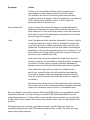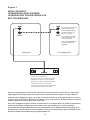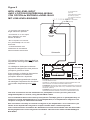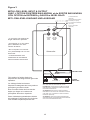
1
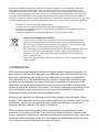
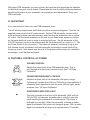
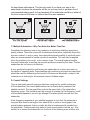
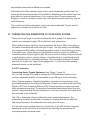
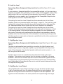
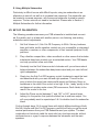
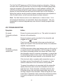
PSB
Powered Subwoofers
OWNER’S GUIDE
www.psbspeakers.com
Contents
i.
Important Safety Instructions
4
II.Introduction
5
III.Quickstart
6
IV. Features, Controls, AC Power
6
V. Room Acoustics, Subwoofer Placement, Multiple Subwoofers & Control Settings
8
VI. Connecting the Subwoofer to Your Audio System
A. LFE Connection
B. Low/Line Level
C. High/Speaker Level
D. High/Speaker Level Output
E. Using Multiple Subwoofers
11
VII. Set-Up Calibration
13
VIII.Troubleshooting
14
Figure 1
16
Figure 2
17
Figure 3
18
Figure 4
19
Figure 5
20
3
I. IMPORTANT SAFETY INSTRUCTIONS
1.
2.
3.
4.
5.
6.
7.
8.
9.
10.
11.
12.
13.
14.
15.
16.
17.
Read these instructions.
Keep these instructions.
Heed all warnings.
Follow all instructions.
Do not use this apparatus near water.
Clean only with dry cloth.
Do not block any ventilation openings. Install in accordance with the manufacturer’s
instructions.
Do not install near any heat sources such as radiators, heat registers, stoves, or other
apparatus (including amplifiers) that produce heat.
Do not defeat the safety purpose of the polarized or grounding-type plug. A polarized
plug has two blades with one wider than the other. A grounding type plug has two
blades and a third grounding prong. The wide blade or the third prong are provided
for your safety. If the provided plug does not fit into your outlet, consult an electrician
for replacement of the obsolete outlet.
Protect the power cord from being walked on or pinched particularly at plugs,
convenience receptacles, and the point where they exit from the apparatus.
Only use attachments/accessories specified by the manufacturer.
Use only with the cart, stand, tripod, bracket, or table specified by the
manufacturer, or sold with the apparatus. When a cart is used, use
caution when moving the cart/apparatus combination to avoid injury from
tip-over.
Unplug this apparatus during lightning storms or when unused for long periods of time.
Refer all servicing to qualified service personnel. Servicing is required when the
apparatus has been damaged in any way, such as power-supply cord or plug is
damaged, liquid has been spilled or objects have fallen into the apparatus, the
apparatus has been exposed to rain or moisture, does not operate normally, or has
been dropped.
The apparatus shall not be exposed to dripping or splashing and that no objects filled
with liquids, such as vases, shall be placed on the apparatus.
WARNING: To reduce the risk of fire or electric shock, this apparatus should not be
exposed to rain or moisture.
The mains plug or an appliance coupler is used as the disconnect device, the
disconnect device shall remain readily operable.
The lightning flash with arrowhead symbol within an equilateral triangle, is intended to alert you to the presence of uninsulated “dangerous voltage” within
the product’s enclosure that may be of sufficient magnitude to constitute a risk of
electric shock to persons.
The exclamation point within an equilateral triangle is intended to alert you to the
presence of important operating and maintenance (servicing) instructions in the
literature accompanying the product.
Notice of FCC Compliance
Warning: Changes or modifications to this unit not expressly approved by the party
responsible for compliance could void the user’s authority to operate the equipment.
NOTE: This equipment has been tested and found to comply with the limits for a Class
B digital device, pursuant to Part 15 of the FCC Rules. These limits are designed to
4
provide reasonable protection against harmful interference in a residential installation.
This equipment generates, uses, and can radiate radio frequency energy and, if not
installed and used in accordance with the instructions, may cause harmful interference
to radio communications. However, there is no guarantee that interference will not occur
in a particular installation. If this equipment does cause harmful interference to radio or
television reception, which can be determined by turning the equipment off and on, the user
is encouraged to try to correct the interference by one or more of the following measures:
•
•
•
•
Reorient or relocate the receiving antenna.
Increase the separation between the equipment and receiver.
Connect the equipment into an outlet on a circuit different from that to which the
receiver is connected.
Consult the dealer or an experienced radio TV technician for help.
Notes on environmental protection
At the end of its useful life, this product must not be disposed of with
regular household waste but must be returned to a collection point for
the recycling of electrical and electronic equipment. The symbol on the
product, user’s manual and packaging, point this out.
The materials can be reused in accordance with their markings. Through
re-use, recycling of raw materials, or other forms of recycling of old
products, you are making an important contribution to the protection
of our environment.
Your local administrative office can advise you of the responsible waste
disposal point.
II. INTRODUCTION
PSB subwoofers are designed to provide the flattest possible frequency response, full
bass extension, low distortion and high output. Beyond these characteristics there are
a few other parameters that we feel are very important in the design of a subwoofer.
First and foremost, a PSB subwoofer must be musical. A subwoofer should also have
the ability to play musically even when overloaded or stressed. For this reason PSB
subwoofers incorporate proprietary limiting circuitry preventing audible overload while
remaining true to the dynamics of the music. This circuitry combines peak limiting circuits
that hold amplifier signal swing to the point just short of the amplifier’s clipping, with
compression circuitry that will reduce the amplifier’s gain.
Managing heat dissipation is challenging with today’s greater power demands. Where
suitable, PSB subwoofers use the latest implementation of super efficient Class D power
amplification, featuring an automatically varying switching frequency that maintains
maximum efficiency and low THD under all conditions.
PSB woofers are always designed to reduce mechanical noise and prevent harsh
sounds at the excursion extremes. Ports have large radius end flares to reduce noise
from air turbulence. Cabinets and amplifiers are designed to prevent air leaks, which can
contribute minute amounts of noise. All of our designs are exhaustively tested to survive
15 continuous hours of being driven to maximum output.
5
Whichever PSB subwoofer you have chosen, we hope that you appreciate the attention
to detail that has gone into its design. Please take the time to read the following sections
about the placement of your subwoofer, its connections and adjustments. Enjoy your
PSB subwoofer.
III. QUICKSTART
If you cannot wait to hear your new PSB subwoofer, then:
Turn off all other components and follow one of the connection diagrams. Connect the
supplied power cord to the AC power socket. Set the PSB subwoofer volume control
to its minimum position (counterclockwise), and then plug the subwoofer into an active
AC outlet. Use the same receptacle as the rest of your audio/video system or another
on the same electrical circuit in order to avoid ground hum. Set the subwoofer’s Sub
Cut-Off Frequency control to its midpoint and set the phase switch or control to 0°. Flip
the Power Switch to the on position. Play bass-rich material, and slowly bring up the
Sub Volume control (clockwise) until the subwoofer contributes a natural level of low
frequency sound. Now please read the rest of this guide and fine-tune your installation
accordingly—it will be time well spent!
IV. FEATURES, CONTROLS, AC POWER
VOLUME CONTROL
Adjusts the output level of the PSB subwoofer only: This is
not intended as a day-to-day volume control. See “VII Setup
Calibration”.
CROSSOVER FREQUENCY CONTROL
Adjusts the upper limit of the subwoofer’s frequency range.
Continuously variable from 50Hz to 150Hz for precise matching of
subwoofer bass reproduction with the main (left and right) stereo
speakers. See “VII Setup Calibration”.
ON/STANDBY INDICATOR LIGHT
The light is located on the front of the subwoofer. With both the
120 and 230 volt versions, the subwoofer is initially in stand-by
mode awaiting the presence of an audio signal. This status is
indicated by a red light. When the subwoofer receives an audio
signal the indicator light colour will change to green. With no audio
signal, the subwoofer will stay on for approximately 15 minutes.
6
PHASE SWITCH OR CONTROL
0
360
Left
Right
Selects the subwoofer output phase between in-phase (0˚) and
out-of-phase (180˚), or up to 360˚ to compensate for the low to mid
bass acoustic effects of different placement locations and listening
rooms. See “VII Setup Calibration”
.
HIGH/SPEAKER LEVEL INPUT TERMINALS
For connecting the PSB subwoofer to receivers or integrated
amplifiers equipped with speaker outputs only. See “ VI Connecting
The Subwoofer to Your Audio System.”
HIGH LEVEL INPUT FROM RECEIVER
Left
HIGH/SPEAKER LEVEL OUTPUT TERMINALS
For connecting the PSB subwoofer to speakers. See “ VI
Connecting The Subwoofer to Your Audio System.”
Right
HIGH LEVEL OUTPUT TO SPEAKERS
LOW LEVEL
INPUT FROM
PREAMP
Left
Right
LOW LEVEL
OUTPUT
TO AMP
Left
Right
LFE INPUT
LFE OUTPUT
LOW/LINE LEVEL INPUT JACKS
For connecting the PSB subwoofer to a separate component
preamplifier, or to an integrated amplifier or receiver with
preamplifier-out/main-in connections, at line level. See “ VI
Connecting The Subwoofer to Your Audio System.”
LOW/LINE LEVEL OUTPUT JACKS
For connecting the PSB subwoofer to a separate component
preamplifier, or to an integrated amplifier or receiver with
preamplifier-out/main-in connections, at line level. See “ VI
Connecting The Subwoofer to Your Audio System.”
LFE JACKS
For connecting the PSB subwoofer to a separate component
preamplifier, or to an integrated amplifier or receiver with LFE/
Subwoofer output connections. See “ VI Connecting The
Subwoofer to Your Audio System.”
7
AC POWER SOCKET
AC POWER SOCKET
Supplies AC power to the PSB subwoofer. Connect the supplied
power cord to the AC power socket. Plug the power cord into
any standard wall outlet. The same receptacle as the rest of the
system or another on the same electrical circuit should be used to
avoid ground hum.
The PSB subwoofer has its own self-contained amplifier and thus
requires AC power (keep this in mind when selecting a location).
You may plug the power cord into any standard wall outlet and
leave the connection in the wall as the PSB subwoofer draws
extremely little current when idle. If you are away for an extended
period you may want to turn off the power switch or unplug your
PSB subwoofer.
POWER SWITCH
The Power Switch turns off the subwoofer’s internal amplifier.
EXTERNAL FUSE
AC POWER SOCKET
When you turn on the subwoofer and there is no LED light and/or
sound, please check the fuse (accessible from the rear panel) to
ensure it is electrically intact. A spare fuse is contained within the
fuseholder compartment behind the inscribed text. Use a wide slot
screwdriver to pry the fuseholder compartment from the AC power
socket. If it is necessary to replace the fuse, use a fuse equivalent
to the type and rating of the fuse shipped with the product. See the
specifications page at the end of the manual for a detail description
of the fuse required for your model of subwoofer.
V. ROOM ACOUSTICS, SUBWOOFER PLACEMENT, MULTIPLE
SUBWOOFERS & CONTROL SETTINGS
A. Room Acoustics
If you are critical about low-frequency response, there’s quite a bit of useful
experimentation you can do, especially in combination with the crossover, level, and
phase controls of our subwoofers.
Begin by considering the size of the listening room. The larger the volume of air a
speaker must move, the more acoustic output is required to achieve the sound levels
you want. In smaller rooms, sound attenuation tends to be offset by reinforcement
8
from wall reflections. In larger spaces, sound has to travel to reach the reflecting
surfaces and then to your ears, which means it has to be louder to begin with. With
traditional full-range speakers, that involves properly matching amplifier power,
speaker sensitivity, impedance and power handling. Most of the power goes to
reproducing bass, so using powered subwoofers and separate midrange/treble
satellites allows for a conservative draw on power from your main amplifier, while
ensuring a good match between the low-frequency amplifier and the woofer.
After size, the most important aspect of a listening room is its shape. In any room,
sound reflects off the walls, ceiling, and floor. If the distance between two opposite
parallel surfaces is a simple fraction of the wavelength of a particular frequency, notes
of that frequency will bounce back and forth in perfect phase—an effect called a
standing wave or room mode. At some point in the room, this note will be reinforced
substantially; at others it will cancel out almost entirely. If the prime listening seat is
placed at either of these locations, the note will be a horrible boom or virtually nonexistent. Almost all rooms are susceptible to some standing waves at low frequencies,
but careful positioning of the speakers and the listening seat can minimize the effects.
The only way to find out what works best is by experimentation.
Speaker positioning may be fairly limited in your room to still get proper imaging, and
some of these positions may still result in standing waves. Use of a subwoofer or two
makes this more controllable. Positioning of the bass speakers has almost no impact
on imaging, so a subwoofer can be positioned with only standing waves in mind.
B. Subwoofer Placement
The loudest bass output from a subwoofer comes from corner placement. The
outward flaring of walls from a corner focuses low frequencies, giving them no place
to go but toward the listener. In the case of subwooofers, there is no penalty in overall
balance for this maximal bass, since your main speakers can be located elsewhere.
In most cases, there should be plenty of bass from corner placement.
If you are seated in a null spot where sound from the subwoofer is cancelled or
diminished by out-of-phase reflections, you will have to move either the subwoofer
or your listening position until you get the desired bass. Flipping the phase control
180 degrees sometimes may make a difference, especially if the null is a product of
cancellations caused by interaction with low frequencies from your main speakers. If
the opposite is happening, where direct and reflected bass waves converge in phase
and produce too strong a peak at your listening position, you can change position or
change your sub’s level control (or possibly the crossover frequency chosen).
The best method for positioning a subwoofer is to put the subwoofer in your listening
chair, then play music with lots of bass through the system (something with steady
low frequencies or continuous test tones). Move around the room and note where
the bass sounds best; if you place the subwoofer in that location, you should get
9
the same bass performance. This test only works if you have your ears at the
same height as where the subwoofer will be, so you may have to get down low. A
recommended starting point for the placement of this subwoofer would be in either of
the front corners of the room, on either side of the main speakers.
C. Multiple Subwoofers—Why Two Subs Are Better Than One
Sometimes the listening room is not conducive to achieving satisfying amounts or
quality of bass. There are rooms with troublesome dimensions, especially those that
are more cubical. In such a case, two subwoofers placed carefully to work with each
other are recommended to handle acoustical anomalies. This can also be applied
when the problem is too much, or too uneven, bass. The overall system benefits
from each subwoofer correcting the acoustic problems caused by the other. The two
subwoofers do not have to be identical.
A very good starting point for positioning two subwoofers is to place one each on
the centre of opposing walls. Experimenting with positioning as previously described
should be used for determining the location of the second subwoofer, except in this
instance one is listening for the minimum amount of bass output.
D. Control Settings
Once a reasonably smooth response has been achieved by careful positioning
of the subwoofers, the overall performance can be fine-tuned by means of the
speaker controls. The low-pass filter controls the upper limit of the subwoofer’s
frequency range. This should be set high enough to overlap the low frequency cutoff
of the satellite speakers, but not high enough to localize specific sounds from the
subwoofer.
If the frequency response of your satellite speakers is such that the subwoofer’s
low-pass filter must be set higher than about 80Hz in order to avoid gaps in the
overall system response, then you might be able to localize specific sounds from
the subwoofer. These sounds may seem to come from beside or behind you. One
solution is to ensure the subwoofer is in the front of the listening area; another is to
10
use multiple subwoofers to diffuse such sounds.
Subwoofers also offer a phase control so the upper frequencies produced will not
cancel out the lower frequencies of the satellites. Adjustment of this control can have
great effect on spectral smoothness in the crossover area. Phase changes with
frequency, however, so these controls may need readjusting every time you vary the
cutoff frequency.
The overall level of the subwoofer’s output may also be adjusted. To gain smooth
response, be careful not to set this too high.
VI. CONNECTING THE SUBWOOFER TO YOUR AUDIO SYSTEM
There are several ways to connect a subwoofer into a system. For best results
overall, we recommend using LFE or Low/Line Level connections.
When making a stereo Low/Line Level connection, be sure to follow the coding on
the cables to maintain left-to-left and right-to-right. Use high quality, well-shielded,
low capacitance RCA cables of minimal necessary length, to avoid picking up noise
in the cable runs. When making a High/Speaker Level connection, in addition to
maintaining left-to-left and right-to-right, be sure to use the coding of the pair of wires
in each speaker cable to maintain phase—+/red/rib/writing to +/red/rib/writing and
-/white/smooth/clear to -/white/smooth/clear. We recommend minimum 16 gauge
wire and, for longer runs, larger (lower gauge) wire. In multi-subwoofer systems
subwoofer inputs can be paralleled.
A. LFE Connection
Connecting Home Theatre Equipment (see Figure 1, page 16):
You can use a single RCA cable to connect the LFE/Subwoofer Output of your
receiver, integrated amplifier, or preamplifier to the LFE Input on the subwoofer.
Home Theatre receivers, integrated amplifiers, surround sound processors, and
preamplifiers usually have a special Subwoofer Output to provide the optional Dolby
Digital or DTS Low Frequency Effects (LFE) Channel present on many movie and
other programming sources. To reproduce these deep-bass effects (when they are
present), supplementing the bass information in the main channels, this output must
be connected to the subwoofer.
The LFE or Subwoofer Output is filtered by most receivers/processors. The
subwoofer’s variable low pass filter is usually not required and will not affect the
frequency response of the subwoofer when using the LFE Input.
In 2-channel source material there is no information in the LFE channel. However,
bass signal can be diverted to the subwoofer by selecting the appropriate AV
receiver/processor surround mode.
11
B. Low/Line Level
Connecting Stereo Equipment Using Low/Line Level (See Figure 2 & 3, page
17-18):
If your receiver or integrated amplifier has preamplifier outputs, or if you are using a
separate preamplifier, the preferred connection is from the Preamplifier Output of the
electronics to the Low Level Input of the subwoofer. Use a dual RCA audio cable.
Additionally, you may need to use Y-connectors at the Preamplifier Output to also
send signals to the Power Amplifier/Main Input.
Connecting the Low/Line Level Outputs from the subwoofer back to the Power
Amplifier Inputs is an important option (see Figure 3, page 18). The Low/Line Level
Inputs of the subwoofer are internally processed through an active high pass filter
(at 12dB/octave below 80Hz) to the Low/Line Level Outputs of the subwoofer.
Connecting the Low/Line Level Outputs from the subwoofer back to the Power
Amplifier Inputs delivers the processed signal, with reduced low frequency content,
to the main speakers. With less low frequency demands, the main speakers can
play louder. Particularly with smaller and/or less efficient main speakers, relieving
speakers other than the subwoofer of the demands of reproducing low frequencies
will allow greater sound output and dynamic capabilities from the other speakers and
from the system overall.
C. High/Speaker Level
Connecting Stereo Equipment with High/Speaker Level (See Figure 4 & 5, page
19-20):
You also can get excellent sonic results by connecting the High/Speaker Level
Output of your receiver, integrated amplifier or power amplifier to the High Level
Input of the subwoofer. Use standard speaker cable and maintain polarity + –, as
well as right and left channel.
Speaker wires can be run onwards from the subwoofer directly to the main
speakers. This replaces running wires from the receiver or amplifier to the main
speakers. Twist the ends of each input wire from the electronics together with the
corresponding wire to the speakers and insert them both into each corresponding
input binding post of the subwoofer. Be sure to avoid all contact between wires into
the separate binding posts.
D. High/Speaker Level Output
Using High/Speaker Level Output (see Figure 4, page 19) allows speaker wires
to be run onwards easily from the subwoofer directly to the main speakers. This
replaces running wires from the receiver or amplifier to the main speakers. The
signals from the subwoofer to the main speakers are looped through, full-range.
12
E. Using Multiple Subwoofers
Particularly in difficult rooms with difficult layouts, using two subwoofers is an
alternative to smooth, as well as to increase bass response. One subwoofer can
be located to increase response, with the second subwoofer located to smooth
response. The two subs do not need to be identical. Please refer to Section V,
Multiple Subwoofers for further information.
VII. SET-UP CALIBRATION
The following procedure assumes your PSB subwoofer is installed and connected. If possible, work in a team with another person: one listening, one making
subwoofer-control adjustments.
1. Set Sub Volume to 0, Sub Cut-Off Frequency to 50Hz. Set any loudness,
bass and treble, and/or equalizer controls on your preamplifier or integrated
amplifier or receiver, or other components, to their nominal (midpoint or off)
positions.
2. Play a familiar compact disc, video soundtrack or other source that includes
substantial deep-bass content over an extended section. Your PSB dealer
can help you select a few such titles.
3. Gradually turn the Sub Volume control clockwise until you achieve natural
balance between the subwoofers deep-bass output and your main left and
right loudspeakers.
4. Slowly turn the Sub Cut-Off Frequency control clockwise to reach the best
mid-bass blend with your main left and right speakers. This will be the
point at which the upper bass retains solid impact and fullness. Boom or
muddiness is the result if the control is too high. A thin, “reedy” quality to the
mid-bass such as deep male voices (FM announcers; Darth Vader) is the
result if the control is too low.
5. Adjust the Phase control between 0° and 180° or 360° several times,
leaving it in the position that yields the fullest low to mid bass output. You
will now probably want to repeat steps 3 & 4 to double-check the subwoofer
blend.
Cycling through steps 3 & 4 several times with slightly different settings of both
the Sub Volume and Sub Cut-Off Frequency controls will help you get the most
musical performance from your PSB Subwoofer and your system. The best
combination is that which yields the most solid very-low-bass sounds, without
mid-bass boom or a gap in response between the subwoofer and the main
speakers.
13
The Sub Cut-Off Frequency and Sub Volume controls are interactive. Raising
the latter while lowering the former can have the effect of extending deep-bass
response somewhat, with a small sacrifice in overall loudness capability (this
will still be well beyond the full-range loudness capability of most systems). In
general, for well-recorded acoustic music the lowest Sub Cut-Off Frequency
setting that yields a smooth transition between subwoofer and main speakers is
often the best choice, and will promote deeper low-bass extension.
Note: The Sub Volume control is not a bass-boost or volume control. It is a
set-and-forget adjustment, not intended for day-to-day adjustment. Use your
preamplifier or receiver/integrated amp tone controls to modify program tonal
balance.
VIII. TROUBLESHOOTING
SymptomAction
No sound
On/standby indicator
not lit Ensure the main power switch is on. This switch is located at
the back of the subwoofer.
Ensure the power cord is connected to the subwoofer and
plugged into a live AC outlet.
Check the main fuse located in the power cord socket and
replace as required. If the new fuse also blows, the subwoofer
amplifier requires service.
No sound
On/standby indicator
remains red
All PSB subwoofers utilize signal sensing auto on/off circuitry. If
no signal is sent to the subwoofer, it will not power up and the
front panel on/standby indicator will remain red. When using
the subwoofer output of a receiver or processor, no signal may
be immediately present in this output. The subwoofer will only
power up when bass signal appears at the subwoofer input.
If the low level cable or speaker cable connection is poor or
has been severed, the subwoofer will not power up. Swap
cables to determine if this is the source of the problem.
To ensure the problem is not associated with the subwoofer,
rapidly disconnect and connect the subwoofer low level or
high level input. If the subwoofer on/standby indicator then
illuminates green, the receiver/processor/amp may not be
sending a signal to the subwoofer. When driving the low level
inputs from a subwoofer output, ensure the receiver/processor
is correctly configured to provide signal at the subwoofer
output.
14
SymptomAction
Further, a red on/standby indicator can be caused by an
overvoltage or undervoltage condition at the AC outlet.
The indicator will also turn red during abnormal operating
conditions such as excessive internal temperature or a presence
of DC voltage at the amplifier output, in which case the
subwoofer needs to be serviced.
Sounds distorted
Lower volume if the subwoofer begins to sound distorted to
determine if playback at a lower level solves the problem. If a
slight reduction in level solves the problem, then the subwoofer
level was too high. If the distorted sound remains at a low level,
driver(s) may be damaged.
Hum
Hum that appears when using the subwoofer’s low level input(s)
is usually caused by using an inferior, damaged, exceptionally
long low level cable or cables routed near high current wiring/
appliances. Replace/shorten the low level cable connecting the
subwoofer to the source equipment (receiver or processor). Low
level cable runs of longer than 20 feet may require the use of a
line driver (not available from PSB).
Hum heard when using the subwoofer’s high level input(s) is
usually caused by an intermittent or missing positive or negative
connection. Ensure there is a good connection between all
speaker wires connecting the subwoofer and receiver/amplifier.
If the subwoofer high level connection is routed through a
switch box, ensure the box shorts the positive and negative
connections together when the subwoofer should be inactive.
Hum will result if the switch box floats the positive or negative
connection.
Decreasing the volume control of the subwoofer and increasing
the volume control of the receiver/processor/amplifier subwoofer
output can sometimes reduce hum to an acceptable level.
See your dealer if you require service. Authorized PSB dealers are equipped to handle
almost all problems. You may locate your nearest PSB authorized dealer on-line at
www.psbspeakers.com. If the problem is not resolved, please contact us, providing the
model name, serial number, date of purchase, dealer name, and a full description of the
problem.
We appreciate your purchase, and hope this owner’s guide helps you enjoy the
exceptional performance that PSB speaker systems have to offer. We wish you many
years of enjoyable listening!
15
Figure 1
WITH LFE INPUT
INTEGRATON AVEC ENTRÉE
INTEGRACIÓN CON ENTRADA LFE
MIT LFE-EINGANG
To LFE INPUT of second
subwoofer (optional)
Vers l’ENTRÉE LFE du
deuxième caisson de
basse (en option)
A LFE INPUT (entrada
LFE) del segundo subwoofer (opcional)
Zum LFE-EINGANG des
zweiten Subwoofers
(optional)
Subwoofer
2nd Subwoofer
A/V Receiver, integrated amplifier, preamplifier or Processor
Récepteur A/V, amplificateur intégré,
préamplificateur ou autre appareil
Receptor AV, amplificador integrado,
preamplificador o procesador
A/V-Receiver, integrierter Verstärker,
Vorverstärker oder Prozessor
Use this configuration to connect the subwoofer to an A/V receiver or processor’s subwoofer/
LFE output provided your A/V receiver/processor subwoofer/LFE output is low pass filtered.
Utilisez cette configuration pour raccorder le caisson de basse à un récepteur A/V ou à la sortie
caisson de basse/LFE d’un appareil à condition que la sortie caisson de basse/LFE du récepteur
A/V/de l’appareil soit dotée d’un filtre passe-bas.
Use esta configuración para conectar el subwoofer a un receptor AV o a la salida de subwoofer/
LFE del procesador, siempre que esas salidas estén procesadas por un filtro pasabajos.
Verwenden Sie diese Konfiguration, um den Subwoofer an den Subwoofer/LFE-Ausgang eines
A/V-Receivers oder Prozessors anzuschließen, unter der Voraussetzung, dass der A/V-Receiver/
Prozessor-Subwoofer/LFE-Ausgang tiefpassgefiltert ist.
16
Figure 2
WITH LOW LEVEL INPUT
AVEC L’OPTION D’ENTRÉE BAS-NIVEAU
CON OPCIÓN de ENTRADA a NIVEL BAJO
MIT LOW-LEVEL-EINGANG
To 2nd Subwoofer
(optional)
Vers le deuxième caisson
de basse (en option)
A un segundo subwoofer
(opcional)
Zum 2. Subwoofer
(optional)
*
* Y connector not required for
single subwoofer operation
*
LOW LEVEL
INPUT FROM
PREAMP
* Connecteur en Y non requis
pour l’utilisation d’un seul
caisson de basse
* No se requiere un conector
en Y para trabajar con un solo
subwoofer
* Y-Steckverbinder nicht
erforderlich für den Betrieb
eines einzelnen Subwoofers
Subwoofer
This method of wiring does not limit low
frequencies reaching left and right main
speakers.
Ce câblage ne limite pas les basses
fréquences atteignant les haut-parleurs
principaux gauche et droite.
Esta conexión no limita las frecuancias
bajas que llegan a los altavoces
principales derecho e izquierdo.
Diese Verkabelungsmethode schränkt
die niedrigen Frequenzen für den linken
und rechten Hauptlautsprecher nicht
ein.
RL
PREAMPLIFIER
PRE- AMP OUT
SPKR / R
SPKR / L
RL
iNPUT / MAiN - iN
POWER
AMPLIFIER
alternate: Receiver or integrated amplifier with pre-amp
out and main-in Jacks
Possibilité : Récepteur ou amplificateur intégré avec préamplificateur et prises d’entrée principales
Alternativa: Receptor o amplificador integrado con salida
de preamplificador (Pre-amp out) y entrada al amplificador
principal (Main-in)
Alternativ: Receiver oder integrierter Verstärker mit
Vorverstärker-Ausgangs- und Haupt-Eingangsbuchsen
Low level connections wire the subwoofer to a preamplifier or to the “pre-out” jacks of an
integrated amplifier or receiver, using standard RCA cables.
Les raccordements bas-niveau relient le haut-parleur d’extrême grave à un préamplificateur ou
aux bornes «sortie préamplificateur» d’un préamplificateur, d’un amplificateur intégré ou d’un
récepteur au moyen de câbles RCA standard.
Para conexión al nivel bajo se conecta el subgrave al pre-amplificador o a los conectores “pre
salida” de un amplificador integrado o receptor usando cables comunes tipo RCA.
Low-Level-Anschlüsse verdrahten den Subwoofer mit einem Vorverstärker oder den Vorverstärkerausgangsbuchsen eines integrierten Verstärkers oder Receivers mittels standardmäßigem
RCA-Kabel.
17
Figure 3
WITH LOW LEVEL INPUT & OUTPUT
AVEC L’OPTION D’ENTRÉE BAS-NIVEAU et de SORTIE BAS-NIVEAU
CON OPCIÓN de ENTRADA y SALIDA a NIVEL BAJO
To 2nd Subwoofer
(optional)
MIT LOW-LEVEL-EINGANG UND-AUSGANG
Vers le deuxième caisson
de basse (en option)
A un segundo subwoofer
(opcional)
Left
Zum 2. Subwoofer
(optional)
Left
*
*
Right
LOW LEVEL
OUTPUT
TO AMP
* Y connector not required for
single subwoofer operation
Right
LOW LEVEL
INPUT FROM
PREAMP
* Connecteur en Y non requis
pour l’utilisation d’un seul
caisson de basse
* No se requiere un conector
en Y para trabajar con un solo
subwoofer
Subwoofer
* Y-Steckverbinder nicht
erforderlich für den Betrieb
eines einzelnen Subwoofers
RL
PREAMPLIFIER
PRE- AMP OUT
This method of wiring limits low
frequencies reaching left and right main
speakers.
Ce câblage limite les basses
fréquences atteignant les haut-parleurs
principaux gauche et droite.
Esta conexión limita las frecuancias
bajas que llegan a los altavoces
principales derecho e izquierdo.
Diese Verkabelungsmethode schränkt
die niedrigen Frequenzen für die linken
und rechten Hauptlautsprecher ein.
SPKR / R
SPKR / L
RL
iNPUT / MAiN - iN
alternate: Receiver or integrated amplifier
with pre-amp out and main-in Jacks
Possibilité : Récepteur ou amplificateur
intégré avec préamplificateur et prises
d’entrée principales
Alternativa: Receptor o amplificador
integrado con salida de preamplificador
(Pre-amp out) y entrada al amplificador
principal (Main-in)
Alternativ: Receiver oder integrierter
Verstärker mit Vorverstärker-Ausgangsund Haupt-Eingangsbuchsen
18
POWER
AMPLIFIER
Figure 4
WITH HIGH LEVEL INPUT & OUTPUT
AVEC ENTRÉE et SORTIE HAUT-NIVEAU
CON ENTRADA y SALIDA de NIVEL BAJO
MIT HIGH-LEVEL-EINGANG UND -AUSGANG
Receiver, integrated amplifier or power
amplifier
Récepteur, amplificateur intégré ou
amplificateur de puissance
Receptor, amplificador integrado o
amplificador de potencia
Receiver, integrierter Verstärker oder
Endverstärker
To 2nd Subwoofer (optional)
Vers le deuxième caisson de
basse (en option)
A un segundo subwoofer
(opcional)
Zum 2. Subwoofer (optional)
HIGH LEVEL
INPUT FROM
RECEIVER
HIGH LEVEL
OUTPUT TO
SPEAKERS
Subwoofer
High level connections wire the subwoofer to the speaker output terminals of a receiver or
amplifier, just as if the subwoofer was a pair of speakers.
Les connexions haut-niveau relient le haut-parleur d’extrême grave aux bornes de sorties h.-p.
d’un récepteur ou d’un amplificateur, comme s’il s’agissait d’une paire d’enceintes acoustiques.
Para conexión al nivel alto se conecta el subgrave a las terminales de salida para altavoz de un
receptor o amplificador como si se tratase de un par de altavoces.
High-Level-Anschlüsse verdrahten den Subwoofer mit den Lautsprecherausgangsterminals
eines Receivers oder Verstärkers, als ob der Subwoofer ein Lautsprecherpaar wäre.
19
Figure 5
WITH HIGH LEVEL INPUT
AVEC ENTRÉE HAUT-NIVEAU
CON ENTRADA de NIVEL BAJO
MIT HIGH-LEVEL-EINGANG
Receiver, integrated amplifier or power
amplifier
Récepteur, amplificateur intégré ou
amplificateur de puissance
Receptor, amplificador integrado o
amplificador de potencia
Receiver, integrierter Verstärker oder
Endverstärker
To 2nd Subwoofer (optional)
Vers le deuxième caisson de
basse (en option)
A un segundo subwoofer
(opcional)
Zum 2. Subwoofer (optional)
HIGH LEVEL
INPUT FROM
RECEIVER
Subwoofer
20
12-037 SubSeries Owner’s Guide