1
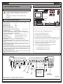
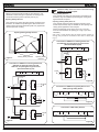
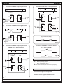
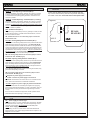
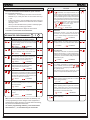
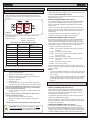
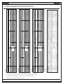
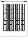
455 D
Control Board
FAAC International Inc.
Headquarter & East Coast Operations
5151 Sunbeam Road
Suites 9-11
Jacksonville, FL 32257
Tel. 866 925 3222
www.faacusa.com
FAAC International Inc.
West Coast Operations
357 South Acacia Avenue
Unit 357
Fullerton, CA 92831
Tel. 800 221 8278
CONTENTS
1. 455 D CONTROL BOARD
3
1.1 455 D Control Board Warnings3
1.2. Technical Specifications
3
1.3 Electric Connections
3
1.4. 455 D Layout and Components
3
1.5 Programming
7
1.6 Start-Up
9
1.7 System Test
10
2. OPERATING MODES DETAILED DESCRIPTION 11
3. PREWIRED ENCLOSURE DIAGRAM
13
4. POWER AND ACCESSORIES CONNECTIONS
14
AC Power Wiring Guidelines
AC Power Connection
Magnetic Lock Connection
14
14
14
LIMITED WARRANTY
15
Read this instruction manual before you begin installing the product.
= Information regarding personal safety and proper maintanence of the product.
= Information regarding the product’s characteristics or operation.
455 D Control Board - Rev: 01 - October 2010
455 D Contr ol Boa r d
2
1.4. 455 D Layout and Components
1. 455 D CONTROL BOARD
1.1 455 D Control Board Warnings
F2
+
–
F
F1
2
OP
COM M1
4
5
OP
COM M2
6
CL
7
8
LAMP
J4
J1
9 10 11 12 13 14 15 16 17 18 19 20 21
A
B
OPEN
STP
CL OP
FSW
-
-
-
+
+
+24V
22
23
24 25
Figure A
-4°F to +131°F
2 (see Fig. A)
Function Logics: Semi-automatic / Automatic / Safety Devices /
“Stepped” Semi-automatic / “Stepped” Automatic / “Stepped” Safety
Devices / Semi-automatic B / Dead-man C
DL SIGNALLING AND PROGRAMMING DISPLAY
Opening/Closing Time
Programmable (from 0 to 120 s)
Pause Time
Programmable (from 0 to 4 min.)
J2 CONNECTOR FOR RP RECEIVER
Closing Leaf Delay
Programmable (from 0 to 4 min.)
Opening Leaf Delay
2 s (can be excluded)
Thrust Force: LOCK
-TX
FSW W.L.
FCC2
1
FCA2
MAIN
L
J6
J5
J6
J5
J1
J4
J3
J3
PE N
Ambient Operating Temperature Range
Protection Fuses
F
FCA1
15 VA
–
FCC1
0,5 A
FCA2
F1
10 W
Electric Lock Max. Load
J2
J2
+
Power Supply 115 V~ ± 10% or 230 V~ +6% -10% 50/60 Hz
Accessories Max. Load
FCC2
FSWCL
1.2. Technical Specifications
800 W
FCC1
STOP
OP_B
Please refer to Chapter 16 for AC power wiring
guidelines
Motor Max. Load
FCA1
OP_A
Important: Before attempting any work on the control
board (connections, maintenance), always turn off
power.
Absorbed Power
DL
FSWOP
F2
J1 LOW VOLTAGE TERMINAL BLOCK
J3 AC POWER SUPPLY TERMINAL BLOCK
J4 MOTORS AND FLASHING LAMP CONNECTION TERMINAL BLOCK
Adjustable on 50 levels for each motor
J5 INDICATOR-LIGHT AND ELECTRIC LOCK TERMINALBLOCK
Terminal Board Inputs: Open / Open Free Leaf / Stop / Limit-switch
Opening Safety Devices / Closing Safety Devices / Power Supply +
Earth.
J6 LIMIT-SWITCH AND GATECODER TERMINAL BLOCK
F1 MOTORS AND TRANSFORMER PRIMARY WINDING FUSE (F 5A - 230V) (F 10A - 115V)
Terminal Board Outputs: Flashing Lamp / Motors / 24 VDC Accessories Power Supply / 24 VDC Indicator-Light / Fail Safe / 12 VAC
Electric Lock Power Supply
F2 LOW VOLTAGE AND ACCESSORIES FUSE (T 800mA)
Programmable Functions: Logic / Pause Time / Thrust Force / Torque
at Initial Thrust / Opening and Closing Leaf Delay / Reversing Stroke
/ Over-Pushing Stroke / Indicator-Light / Pre-Flashing / Electric Lock /
Fail Safe / Safety Devices Logic / Assistance Request / Detection Time
of Obstacle or Contact Point
F
“F” PROGRAMMING PUSH-BUTTON
–
“–” PROGRAMMING PUSH-BUTTON
+
“+” PROGRAMMING PUSH-BUTTON
Learning Function: Simple or complete work time learning, with or
without Limit-switch and/or Gatecoder.
BLUE
BLUE
FCC2
1.3 Electric Connections
VAC MAX.
60W
230 VAC
50 Hz
or
115 VAC
60 Hz
24 V DC
3W
OPEN A
OPEN B
STOP
NB: Capacitors are supplied with the operator.
455 D Contr ol Boa r d
For connection
of the photocells and safety
devices, see
Section 13.4.1.
12 V AC
LIMIT-SWITCH
OR GATECODER
Figure B
3
NOTE: All safety devices must be connected using
NORMALLY CLOSED outputs.
1.4.1 Connection of Photocells and Safety Devices
Before connecting the photocells (or other devices), it is
advisable to select the type of operation according to the
movement area they have to protect (see Fig.C):
Opening Safety Devices:
They operate only during the gate opening movement and,
therefore, are suitable for protecting the area between the
opening leaves and fixed obstacles (walls, etc) against the
risk of impact and crushing.
Opening/Closing Safety Devices
Closing Safety Devices:
They operate only during the gate closing movement and,
therefore, they are suitable for protecting the closing area
against the risk of impact.
Opening/Closing Safety Devices:
They operate during the gate opening and closing movements and, therefore, they are suitable for the opening and
closing areas against the risk of impact.
FAAC recommends use of the lay-out in Fig. D (in the
event of fixed obstacles at opening) or in Fig. E (no fixed
obstacles).
N.B. If two or more devices have the same function (opening or
closing), they should be connected to each other in series (see
Fig. L).
Connection of ONE Pair of Closing Photocells
and ONE Pair of Opening/Closing Photocells
(Recommended Layout)
9 10 11 12 13 14 15 16 17 18 19 20 21
B
A
OPEN
STP
CL OP
FSW
-
-
-
RX CL
Figure C
STP CL OP
FSW
-
-
-
+ +
+24V
- 1
3
-TX FSW
+
+ 2
4 -
+
5 +
TX OP/CL
RX OP/CL
1
9 10 11 12 13 14 15 16 17 18 19 20 21
A B
OPEN
TX CL
2
-
Connection of ONE Pair of Closing Photocells,
ONE Pair of Opening Photocells and
ONE Pair of Opening/Closing Photocells
(Recommended Layout)
LOCK
-TX
FSW W.L.
1
Opening Safety
Devices
Closing Safety Devices
+ +
+24V
LOCK
-TX
FSW W.L.
2
1 -
-TX FSW
+
3
2 +
-
- 4
+
+ 5
RX CL
TX CL
Figure E
1
2
-
+
3
4 -
- 1
+ 2
-TX FSW
+
5 +
TX OP/CL
9 10 11 12 13 14 15 16 17 18 19 20 21
RX OP/CL
B
A
OPEN
1
-TX FSW
+
1 2 +
2
3
- 4
+ 5
Connection of ONE Closing Safety Device and
ONE Opening Safety Device
STP
CL OP
FSW
-
-
-
+
+
+24V
-TX
FSW
W.L.
LOCK
-
+
Figure F
Connection of NO Safety Devices
RX OP
TX OP
1
2
3
-
+
Figure D
455 D Contr ol Boa r d
4 -
- 1
+ 2
-TX FSW
+
9 10 11 12 13 14 15 16 17 18 19 20 21
B
A
OPEN
STP
CL OP
FSW
-
-
-
+
+
+24V
-TX
FSW
W.L.
LOCK
5 +
Figure G
4
Connection of TWO Pairs of Closing Photocells
Connection of ONE Pair of Opening Photocells
9 10 11 12 13 14 15 16 17 18 19 20 21
9 10 11 12 13 14 15 16 17 18 19 20 21
B
A
OPEN
CL OP
FSW
STP
-
-
+
+
+24V
-
RX OP
A B
OPEN
LOCK
-TX
FSW W.L.
RX CL1
TX OP
-
-
+ +
+24V
LOCK
-TX
FSW W.L.
TX CL1
2
2
- 1
3
-TX FSW
+
+ 2
4 -
+
-
1
1
-
STP CL OP
FSW
5 +
-
+
+ 2
4 -
+
-TX FSW
- 1
3
5 +
Figure H
TX CL2
RX CL2
1
Connection of ONE Pair of Closing Photocells
-TX FSW
+
1 2 +
9 10 11 12 13 14 15 16 17 18 19 20 21
B
A
OPEN
CL OP
FSW
STP
-
-
+
+
+24V
-
2
3
-
- 4
+
+ 5
LOCK
-TX
FSW W.L.
Figure K
RX CL
TX CL
1
2
- 1
3
-
+
+
+ 2
4 -
Connection of TWO N.C. Contacts in Series
(e.g. Photocells, Stop)
-TX FSW
5 +
Figure I
Figure L
Connection of ONE Pair of Opening Photocells
and ONE Pair of Closing Photocells
Connection of TWO N.O. Contacts in Parallel
(e.g. Open A, Open B)
9 10 11 12 13 14 15 16 17 18 19 20 21
B
A
OPEN
STP
CL OP
FSW
RX OP
-
-
-
+ +
+24V
LOCK
-TX
FSW W.L.
Figure M
TX OP
1
2
-
+
3
4 -
- 1
+ 2
-TX FSW
+
PE:
N:
L:
5 +
TX CL
RX CL
+
1 2 +
2
3
- 4
+ 5
Earth Connection / Ground
AC V~ power supply (Neutral)
AC V~ power supply (Line)
NB: For correct operation, the board must be properly
grounded.
1
-TX FSW
1.4.2 Terminal Block J3 - Power Supply (Fig. B)
-
+
1.4.3 Terminal Block J4 - Motors and Flashing Lamp
M1:
COM / OP / CL: Connection to Motor 1
Can be used in single-leaf configuration
M2:
COM / OP / CL: Connection to Motor 2
Cannot be used in single-leaf configurations
Figure J
455 D Contr ol Boa r d
LAMP: Flashing lamp output ( AC V ~)
5
1.4.4 Terminal Block J1 - Accessories (Fig. B)
OPEN A - “Total Opening” Command (N.O.):
Any pulse generator (push-button, detector, etc.) which, by closing
a contact, commands opening and/or closing of both gate leaves.
To install several full opening pulse generators, connect the N.O.
contacts in parallel.
OPEN B - “Partial Opening” Command (N.O.) / Closing:
Any pulse generator (push-button, detector, etc.) which, by closing
a contact, commands opening and/or closing of the leaf driven by
motor M1. In the B and C logics, it always commands closing of both
leaves. To install several partial opening pulse generators, connect
the N.O. contacts in parallel.
1.4.6 Connector J2 - Rapid Connection to RP
Receivers
This is used for rapid connection to RP receivers (see Fig.
Q). Connect the accessory with the components side facing
the inside of the card. Insert and remove with power OFF.
Figure Q
STP - STOP Contact (N.C.):
RP 1418
RP 433 RC
Any device (e.g. a push-button) which, by opening a contact, is able
to stop gate movement. To install several STOP devices, connect
the N.C. contacts in series.
NB: If STOP devices are not connected, jumper connect the
STP terminals and -.
CL FSW - Closing Safety Devices Contact (N.C.):
455 D
The purpose of the closing safety devices is to protect the leaf movement area during closing. During closing, in the E-A-S-EP-AP-SP
logics, the safety devices reverse the movement of the gate leaves,
or stop and reverse the movement when they are released (see Advanced Programming in Section 13.5.2). During the closing cycle in
logics B and C, they interrupt movement. They never operate during
the opening cycle. If the closing safety devices operate when the
gate is open, they prevent the leaf closing movement.
NB: If no closing safety devices are connected, jumper connect
terminals CL and -TX FSW (Fig. G).
OP FSW - Opening safety devices contact (N.C.):
The purpose of the opening safety devices is to protect the leaf movement area during opening. During opening, in the E-A-S-EP-AP-SP
logics, the safety devices reverse the movement of the gate leaves.
During the opening cycle in logics B and C, they interrupt movement.
They never operate during the closing cycle.
If the opening safety devices operate when the gate is closed, they
prevent the leaf opening movement.
NB: If no opening safety devices are connected, jumper connect
inputs OP and -TX FSW (Fig. G).
– - Negative for power supply to accessories
+ - 24 VDC - Positive for power supply to accessories
Important: Accessories max. load is 500 mA. To calculate current
draw, refer to the instructions for individual accessories.
-TX FSW - Negative for power supply to photocell transmitters.
If you use this terminal for connecting the negative for supplying
power to the photocell transmitters, you may, if necessary, also use
the FAIL SAFE function (see Advanced Programming in Section
13.5.2).
If this function is enabled, the equipment checks operation of the
photocells before each opening or closing cycle.
1.4.5 Terminal Block J5 - Indicator-Light and Electric
Lock
W.L. - Power supply to indicator-light
Connect a 24 VDC - 3 W max. indicator-light, if necessary, between
this terminal and the +24V supply. To avoid compromising correct
operation of the system, do not exceed the indicated power.
LOCK - Power supply to electric lock
If necessary, connect a 12 VAC electric strike lock between this
terminal and the +24V power supply. Please refer to Chapter 16 for
Magnetic Lock connection.
455 D Contr ol Boa r d
6
1.5 Programming
1.4.7 Terminal Block J6 - Limit-Switch or Gatecoder
These inputs are designed for connection of opening
and closing limit-switches or Gatecoders
The 400 operator cannot use limit switches but only
Gatecoders. They are used to detect the leaf’s angular
position and to thus obtain deceleration and stop
positions more accurately than using the operating
timing.
Please refer to Figure S for wiring information. If the
Gatecoders are not used the J6 inputs can be left
unconnected.
Figure S
To program the 455D Control Board, you have to access “PROGRAMMING” mode. Programming is split into two parts: BASIC and
ADVANCED.
1.5.1 Basic Programming
To access BASIC PROGRAMMING, press key F:
•
Press and hold F, the unit will display the name of the first function / parameter.
•
When you release the key, the unit will display the parameter’s
current value.
•
Value can be modified with keys + and - .
•
Press and hold F again, the unit will display the name of the next
function / parameter.
•
When you reach the last function, press F to exit the program,
the display resumes monitoring input status.
FCC2
The following table displays the sequence of functions
accessible in BASIC PROGRAMMING:
BASIC PROGRAMMING
Display
press
F
Function
Default
OPERATING LOGICS (see tab. 3/a - h):
RED
= Semi-automatic
= Automatic
= “Safety” Automatic
= “Stepped” Semi-automatic
= “Stepped” Automatic
= “Safety Stepped” Automatic
= “B” Semi-automatic
= Dead-man
WHITE
BLACK
RED
WHITE
BLACK
PAUSE TIME:
1.4.8 Operating Logics
This is a brief description of the main operating logics of the
system. For a complete description please refer to Table 3
•
•
•
•
•
•
A (automatic): The gate opens on command and automatically closes after a pause phase. A second command while opening is ignored; a second command during the pause phase interrupts the pause time; a second
command during closing reopens the gate. A maintained
open command will hold the gate open.
S (security): The security mode is like A logic except that
a second command during opening immediately closes
the gate. A maintained open command will not hold the
gate open.
E (semi-automatic): This mode requires a second command during opening stops the gate. A second command
during closing reopens the gate.
EP (semi-automatic, step by step): This mode requires
a command to open and a command to close. A second
command during opening or closing causes the gate to
stop. A third command then reverses the previous motion
of the gate.
B (manned, pulsed): This mode is designed for guard
station use and requires a three button switch (pulsed) to
open, close, and stop the gate.
C (manned and constant): This mode requires constant
pressure switches. One to open and one to close. No
pressure on a switch stops the gate.
This has effect only when automatic logic is selected.
Adjustable from
to
secs. in one-second
increments.
Subsequently, display changes to minutes and tenths
of seconds (separated by a decimal point), time
is adjusted in 10-second increments, up to
minutes max. Thus, if the unit displays
, Pause
Time is 2 mins. and 50 secs.
LEAF 1 FORCE:
Adjusts thrust of Motor 1.
= minimum force
= maximum force (hydraulic)
LEAF 2 FORCE:
Adjusts thrust of Motor 2.
= minimum force
= maximum force (hydraulic)
LEAF 1 CLOSING DELAY:
Delays closing start of leaf 1 with respect to
leaf 2. Adjustable from
to
minutes (see
Pause Time).
TIME LEARNING (see Section F.3.):
Enables the selection between “simple”
(automatic) learning and “complete” (manual
choice of deceleration and stop points) learning.
Simple Learning:
Complete Learning:
+
≈ 1 s.
+
> 3 s.
Exit from programming and return to inputs status
monitoring.
If using hydraulic operators, set force to maximum level.
455 D Contr ol Boa r d
7
Display
1.5.2 Advanced Programming
To access ADVANCED PROGRAMMING, press and hold
key F and then press key +:
•
Release key +, the unit displays the name of the first function.
•
Release key F, modify the value of the function with keys
+ and -.
•
Press and hold key F, the unit displays the name of the next
function, and if you release it, the value that can be modified
with keys + and -.
•
When you reach the last function, press F to exit the program,
the unit resumes monitoring input status.
The following table shows the sequence of functions
accessible in ADVANCED PROGRAMMING:
ADVANCED PROGRAMMING F
Display
+
Function
+
Default
Function
If
is selected, the output functions as a
standard indicator-light (lighted at opening and
pause, flashing at closing, and off when gate is
closed). Different figures correspond to the extra
time compared to normal work time (opening or
closing) when the output can be used - via a relay
- to power a courtesy light. Time can be adjusted
from
to
sec. in 1 sec. steps, and from
to
min. in 10 sec. steps.
= Standard indicator-light
from to
= Timed output
CLOSING PHOTOCELLS REVERSE AT
RELEASE:
Enable this function if you want the closing
photocells to stop movement and reverse at
release. Default setting is immediate reverse.
= Active
= Disabled
MAXIMUM TORQUE AT INITIAL THRUST:
A.D.M.A.P. FUNCTION:
The motors operate at maximum torque (ignoring
the torque setting) at start of movement. Useful
for heavy leaves.
When enabled, the safety devices operate in
compliance with French standard NFP 25/362.
= Active
= Disabled
LAST STROKE AT CLOSING:
The motors are activated at full speed for 1
second to facilitate locking of the electric lock.
= Active
=Disabled
REVERSING STROKE:
Before opening, while the gate is closed, the
motors thrust to close for 2 seconds thus
facilitating release of the electric lock.
= Active
= Disabled
LEAF 2 OPENING DELAY (2 s):
Enables delayed start (at opening) of leaf 2,
avoiding interference between leaves.
= Active
= Disabled
FAIL SAFE:
If this function is activated, it enables a function
test of the photocells before any gate movement.
If the test fails (photocells not serviceable), the
gate does not start the movement.
= Active
= Disabled
PRE-FLASHING (5 s):
Activates the flashing lamp for 5 seconds before
start of movement.
= Active
= Disabled
ELECTRIC LOCK ON LEAF 2:
For using the electric lock on leaf 2 instead of
on leaf 1.
= Active
= Disabled
Default
INDICATOR-LIGHT:
= Active
= Disabled
ASSISTANCE REQUEST (combined with
next function):
If activated, at the end of countdown (settable
with the next function i.e. “Cycle programming”)
it affects 8 s of pre-flashing at every Open pulse
(job request). Can be useful for setting scheduled
maintenance jobs.
= Active
= Disabled
CYCLE PROGRAMMING:
For setting countdown of system operation
cycles. Settable (in thousands) from
to
thousand cycles. The displayed value is updated
as cycles proceed.
This function can be used to check use of the
board or to exploit the “Assistance request”.
ANTI-CRUSHING SENSITIVITY:
When operating with the gatecoder, it controls
anti-crushing sensitivity.
= Low = High.
EXTRA WORK TIME:
When operating without a gatecoder and limitswitch, if reversing occurs, and if the leaf does
not reach its end contact point, you can activate
this function to increase work time.
= Active
= Disabled
Exit from programming and return to inputs
status monitoring.
NB: Parameter modifications take effect immediately. Exit
out of programming to save changes. If the equipment is
powered down before returning to normal status monitoring,
any unsaved modifications will be lost.
To restore programming defaults, press and hold the
three buttons +, -, F simultaneously for 5 seconds.
455 D Contr ol Boa r d
8
1.6 Start-Up
1.6.3 Learning Operating Times
Opening/closing time is established by a learning procedure which
varies slightly according to whether you are using Gatecoders or not.
1.6.1 LED Check
The board has a two-digit display. When not in “PROGRAMMING”
mode, this display is used to indicate the status of inputs. Fig. U
shows how the LED segments of the display exactly correspond to
the inputs.
13.6.3.1 LEARNING NORMAL TIMES
Normal learning (i.e. without limit-switches and Gatecoders) can be
accomplished in two ways:
- SIMPLE LEARNING (Without Slow Down):
Check that the leaves are closed. Enter “BASIC PROGRAMMING,”
select the TIME LEARNING function and then press the + pushbutton for 1 second. The display begins flashing and the leaves
begin to open.
As soon as the leaves reach the opening contact point, provide an
OPEN A pulse (with the key operated push-button or with the radio
control) to stop the movement. The leaves stop and the display
stops flashing.
Figure U
The table below shows the status of the LEDs in relation to the
status of the inputs.
Note the following:
LED ON = closed contact
LED OFF = open contact
Operation of the Status Signaling LEDs
Press push-button F to exit and save the programming. The
procedure is complete and the gate is ready to operate.
- COMPLETE LEARNING (With Slow Down):
Check that the leaves are closed. Enter “BASIC PROGRAMMING,”
select the TIME LEARNING function and then press the + pushbutton for more than 3 seconds. The display begins flashing and
leaf 1 begins to open. The following functions can be performed by
sending OPEN A pulses (by key push-button or radio control):
LEDs
ON
OFF
OP_A
Command activated
Command inactive
1° OPEN - Slow down at opening of leaf 1
OP_B
Command activated
Command inactive
STOP
Command inactive
Command activated
2° OPEN - Leaf 1 stops at opening and leaf 2 begins its opening
movement
FSWCL
Safety devices clear
Safety devices triggered
FSWOP
Safety devices clear
Safety devices triggered
FCA1 (if used)
Flashes when Gatecoder 1 is in use
FCC1 (if used)
Flashes when Gatecoder 1 is in use
FCC2 (if used)
Flashes when Gatecoder 2 is in use
FCA2 (if used)
Flashes when Gatecoder 2 is in use
The status of the LEDs while the gate is closed at rest are shown in bold.
1.6.2 Rotation Direction and Force Check
1. Program the functions of the 455 D control board according to
need, as previously shown.
2. Cut power to the electronic control equipment.
3. Release the operators and manually move the gate to the
mid-point of the opening angle.
4. Re-lock the operators.
5. Restore power.
6. Send and opening command on the OPEN A input (Fig.B)
and check if the gate leaves are being commanded to open.
N.B: If the first OPEN A pulse commands a closing, cut power
and reverse the phases of the electric motor (red and black
wires) on the 455 D control board.
7. Check force setting of the motors, modify if necessary (see
Section 13.5.1).
N.B: For hydraulic operators, like the 400, force should be programmed to maximum level (50)
8. Stop leaf movement with a STOP command.
9. Release the operators, close the leaves and re-lock the
operators.
Make sure travel limit mechanical stops are present.
WARNING: During the learning procedure, safety
devices are disabled! Avoid crossing the leaf
movement area when this operation is carried out.
455 D Contr ol Boa r d
3° OPEN - Slow down at opening of leaf 2
4° OPEN - Leaf 2 stops at opening and immediately begins its
closing movement
5° OPEN - Slow down at closing of leaf 2
6° OPEN - Leaf 2 stops at closing and leaf 1 begins its closing
movement
7° OPEN - Slow down at closing of leaf 1
8° OPEN - Leaf 1 stops at closing
When the display stops flashing, press push-button F to exit and
save the programming. The procedure is complete and the gate is
ready to operate.
Notes:
• If you wish to eliminate deceleration in certain stages, wait for the
leaf to reach its stop-limit and supply 2 consecutive Open pulses
(by 1 second).
• If only one leaf is present, the entire sequence must nevertheless
be effected. When the leaf has finished opening, supply 5 Open
pulses until the leaf begins to close, and then resume normal
operation.
1.6.4 Learning Times with Gatecoder
Learning with the Gatecoder can be accomplished in two ways:
- SIMPLE LEARNING (With Slow Down):
Check that the leaves are closed. Access “BASIC PROGRAMMING,” select the TIME LEARNING function and then press the
+ push-button for 1 second: the display begins flashing and the
leaves begin the opening movement.
The movement stops automatically when the opening stop limit is
reached. The display will stop flashing.
Press push-button F to exit and save the programming. The procedure is complete and the gate is ready to operate, using the default
slow down set at the factory.
- COMPLETE LEARNING (With Slow Down):
Check that the leaves are closed. Access “BASIC PROGRAMMING,” select the TIME LEARNING function and then press the +
push-button for more than 3 seconds. The display begins flashing
and leaf 1 begins to open. The following functions can be performed
by sending OPEN A pulses (by radio control or key push-button):
9
1° OPEN -Leaf 1 slows down at opening (it stops automatically on
reaching the stop limit)
2° OPEN -Leaf 2 opening movement begins
3° OPEN -Leaf 2 slows down at opening (it stops automatically on
reaching the stop limit)
4° OPEN -Leaf 2 closing movement begins
5° OPEN - Leaf 2 slows down at closing (it stops automatically on
reaching the stop limit)
6° OPEN - Leaf 1 closing movement begins
7° OPEN - Leaf 1 slows down at closing (it stops automatically on
reaching the stop limit)
8° OPEN - End of learning
When the display stops flashing, press push-button F to exit and
save the programming. The procedure is complete and the gate is
ready to operate.
Notes:
•
The slow down pulse should be given before the gate reaches
the positive stop to prevent the leaf from hitting it at full speed
(it would be mistaken for an obstacle).
•
If only one leaf is present, the entire sequence must nevertheless be effected. When the leaf has finished opening, supply
5 Open pulses until the leaf begins to close, and then resume
normal operation.
1.7 System Test
When you are finished programming, test the system. Verify that
the entire system operates correctly. Most importantly, check that
force is adequately adjusted and that safety devices are operating
correctly.
455 D Contr ol Boa r d
10
455 D Contr ol Boa r d
S t o p s o p e r a t io n ( 3 )
C lo s e s t h e le a f ( w it h C lo s in g S a f e t y d e v ic e s e n g a g e d ,
o p e n s a t t h e 2 n d p u ls e ) ( 3 )
O P E N IN G
LO C K ED
N o e ffe c t (1 ) (3 )
C lo s e s t h e le a f ( 3 )
O P E N IN G
LO C K ED
Logic "EP"
OPENING
(always closes after a Stop)
Restarts movement in reverse direction (3)
Stops operation
Stops operation (3)
LOCKED
opening time
Opens leaf for the partial
Re-closes the leaf immediately (3)
Opens the leaf
CLOSING
OPEN
CLOSED
GATE STATUS
OPEN-B
C lo s e s t h e le a f ( 3 )
LO C K ED
OPEN-A
R e - c lo s e s t h e le a f im m e d ia t e ly ( 3 )
O P E N IN G
Tab. 3/d
R e - o p e n s t h e le a f im m e d ia t e ly
C L O S IN G
C LO SED
R e - c lo s e s t h e le a f im m e d ia t e ly ( 3 )
O p e n s s in g le le a f a n d c lo s e s
a f t e r p a u s e t im e
O p e n s t h e le a f a n d c lo s e s
it a f t e r p a u s e t im e
O P E N o n PA U S E
O PEN - B
O PEN -A
G A T E S TA T U S
L o g ic " S "
Tab. 3/c
R e - o p e n s t h e le a f im m e d ia t e ly ( 1 )
C L O S IN G
C LO SED
R e lo a d s p a u s e t im e ( 1 ) ( 3 )
O p e n s s in g le le a f a n d c lo s e s
a f t e r p a u s e t im e ( 1 )
O p e n s t h e le a f a n d c lo s e s
it a f t e r p a u s e t im e ( 1 )
O P E N o n PA U S E
O PEN - B
O PEN -A
G A T E S TA T U S
L o g ic " A "
Tab. 3/b
R e - o p e n s t h e le a f im m e d ia t e ly
C L O S IN G
O p e n s s i n g l e l e af
R e - c lo s e s t h e le a f im m e d ia t e ly ( 3 )
O p e n s t h e le a f
C LO SED
O PEN - B
O PEN
O PEN -A
G A T E S TA T U S
L o g ic " E "
Tab. 3/a
(OPEN disabled)
No effect
operation
Stops
STOP
N o e ffe c t
( O P E N d is a b le d )
S to p s
o p e r a t io n
STO P
N o e ffe c t
( O P E N d is a b le d )
S to p s
o p e r a t io n
STO P
N o e ffe c t
( O P E N d is a b le d )
S to p s
o p e r a t io n
STO P
PU LSES
PU LSES
PU LSES
(if it must open, it disables OPEN)
No effect
see paragraph 5.2.
No effect (saves OPEN)
disabled)
No effect (if on part.opng. OPEN A
(OPEN disabled)
No effect
OPENING SAFETY DEVICES
PULSES
N o e ffe c t
(if it must close, it disables OPEN)
No effect
No effect
see paragraph 5.2.
No effect (OPEN disabled) (3)
No effect
CLOSING SAFETY DEVICES
No effect (OPEN disabled)
opening
Locks and, on release, continues
open
Locks and, on release, reverses to
No effect (OPEN disabled)
No effect (OPEN disabled)
OP/CL SAFETY DEVICE
N o e ffe c t
O P E N d is a b le d )
L o c k s a n d , o n r e le a s e , c o n t in u e s
o p e n in g
N o e ffe c t
(sa v e s O P E N )
R e v e r s e s t o c lo s e
L o c k s a n d , o n r e le a s e , r e v e r s e s t o
open
s e e p a ra g ra p h 5 .2 .
N o e ffe c t
(sa v e s O P E N )
O n r e le a s e , c lo s e s a f t e r 5 "
( O P E N d is a b le d )
N o e ffe c t
( O P E N d is a b le d )
O P / C L S A F E T Y D E V IC E
O n r e le a s e , c lo s e s a f t e r 5 " ( O P E N
d is a b le d ) ( 3 )
N o e ffe c t
C L O S IN G S A F E T Y D E V IC E S
N o e ffe c t
( O P E N d is a b le d )
L o c k s a n d , o n r e le a s e , c o n t in u e s
o p e n in g
L o c k s a n d , o n r e le a s e , r e v e r s e s t o
open
R e lo a d s p a u s e t im e ( 1 )
( O P E N d is a b le d )
N o e ffe c t
( O P E N d is a b le d )
O P / C L S A F E T Y D E V IC E
N o e ffe c t
( O P E N d is a b le d )
L o c k s a n d , o n r e le a s e , c o n t in u e s
o p e n in g
N o e ffe c t
( if o n p a r t . o p n g . O P E N A d is a b le d )
N o e ffe c t
( O P E N d is a b le d )
N o e f f e ct
s e e p a ra g ra p h 5 .2 .
R e lo a d s p a u s e t im e ( 1 ) ( 3 )
N o e ffe c t
C L O S IN G S A F E T Y D E V IC E S
N o e ffe c t
O P E N IN G S A F E T Y D E V IC E S
R e v e r s e s t o c lo s e
N o e ffe c t
(sa v e s O P E N )
N o e ffe c t
( if o n p a r t . o p n g . O P E N A d is a b le d )
N o e ffe c t
( O P E N d is a b le d )
N o e f f e ct
L o c k s a n d , o n r e le a s e , r e v e r s e s t o
open
N o e ffe c t
( O P E N d is a b le d )
N o e ffe c t (3 )
( O P E N d is a b le d )
s e e p a ra g ra p h 5 .2 .
N o e ffe c t
( O P E N d is a b le d )
O P / C L S A F E T Y D E V IC E
N o e ffe c t
C L O S IN G S A F E T Y D E V IC E S
N o e ffe c t
O P E N IN G S A F E T Y D E V IC E S
R e v e r s e s t o c lo s e
N o e ffe c t
(sa v e s O P E N )
N o e ffe c t
( if o n p a r t . o p n g . O P E N A d is a b le d )
N o e ffe c t
( O P E N d is a b le d )
O P E N IN G S A F E T Y D E V IC E S
2. OPERATING MODES DETAILED DESCRIPTION
(1) If maintained, it prolongs the pause until disabled by the command (timer function)
(2) If a new pulse occurs within 2 seconds after reversing, it immediately stops operation.
(3) During the partial opening cycle, an OPEN A pulse causes total opening.
NB.: Effects on other active pulse inputs in brackets.
11
(1) If maintained, it prolongs the pause until disabled by the command (timer function)
(2) If a new pulse occurs within 2 seconds after reversing, it immediately stops operation.
(3) During the partial opening cycle, an OPEN A pulse causes total opening.
NB.: Effects on other active pulse inputs in brackets.
455 D Contr ol Boa r d
12
S t o p s o p e r a t io n ( 3 )
C lo s e s t h e le a f ( w it h C lo s in g S a f e t y d e v ic e s e n g a g e d ,
o p e n s a t t h e 2 n d p u ls e ) ( 3 )
O P E N IN G
LO C K ED
C lo s e s t h e le a f ( 3 )
LO C K ED
N o e ffe c t
R e v e rs e s to o p e n
N o e ffe c t
O p e n s t h e le a f
O PEN
C L O S IN G
O P E N IN G
LO C K ED
C lo s e s t h e le a f
O p e n s t h e le a f
N o e ffe c t
( O P E N - B d is a b le d )
S t o p s o p e r a t io n
/
C LO SED
O PEN
C L O S IN G
O P E N IN G
S t o p s o p e r a t ion
/
N o e ffe c t
( O P E N - A d is a b le d )
O P E N - B ( c lo s in g )
O P E N - A ( o p e n in g )
G A T E S TA T U S
L o g ic " C "
C l o s e s t h e l e af
N o e f f e ct
N o e f f e ct
C l o s e s t h e l e af
N o e f f e ct
C O N T R O L S A LW AY S H E L D D O W N
O p e n s t h e le a f
C LO SED
Tab. 3/h
O P E N - A ( o p e n in g )
L o g ic " B "
G A T E S TA T U S
O P E N - B ( c lo s in g )
S t o p s o p e r a t io n ( 3 )
Tab. 3/g
R e - o p e n s t h e le a f im m e d ia t e ly
C L O S IN G
O P E N IN G
S t o p s o p e r a t io n ( 3 )
O p e n s s in g le le a f a n d c lo s e s
a f t e r p a u s e t im e
O p e n s t h e le a f a n d c lo s e s
it a f t e r p a u s e t im e
C LO SED
O P E N o n PA U S E
O PEN - B
O PEN -A
G A T E S TA T U S
L o g ic " S P "
Tab. 3/f
R e - o p e n s t h e le a f im m e d ia t e ly
C L O S IN G
C LO SED
S t o p s o p e r a t io n ( 3 )
O p e n s s in g le le a f a n d c lo s e s
a f t e r p a u s e t im e
O p e n s t h e le a f a n d c lo s e s
it a f t e r p a u s e t im e
O P E N o n PA U S E
O PEN -B
O PEN -A
G A T E S TA T U S
L o g ic " A P "
Tab. 3/e
S t o p s o p e r a t io n
N o e ffe c t
(O PEN -A /B disabled)
STO P
N o e ffe c t
(O PEN A /B d isa b led )
S to p s
o p e r a t io n
N o e ffe c t (O P E N
B d is a b le d )
STO P
N o e ffe c t
( O P E N d is a b le d )
S to p s
o p e r a t io n
STO P
N o e ffe c t
( O P E N d is a b le d )
S to p s
o p e r a t io n
STO P
PU LSES
PU LSES
PU LSES
N o e ffe c t
( O P E N B d is a b le d )
N o e ffe c t
( O P E N - A d is a b le d )
N o e ffe c t
S t o p s o p e r a t io n
( O P E N - B d is a b le d )
N o e ffe c t
N o e ffe c t
N o e ffe c t
( O P E N B d is a b le d )
S t o p s o p e r a t io n
( O P E N - A d is a b le d )
N o e ffe c t
( O P E N A d is a b le d )
N o e ffe c t
( O P E N A d is a b le d )
C L O S IN G S A F E T Y D E V IC E S
PU LSES
N o e ffe c t
N o e ffe c t
(sa v e s O P E N A )
S t o p s o p e r a t io n
( O P E N - A d is a b le d )
O P E N IN G S A F E T Y D E V IC E S
S t o p s o p e r a t io n
( O P E N - B d is a b le d )
N o e ffe c t
N o e ffe c t
C L O S IN G S A F E T Y D E V IC E S
N o e ffe c t
( O P E N B d is a b le d )
N o e ffe c t
( O P E N A d is a b le d )
O P E N IN G S A F E T Y D E V IC E S
S t o p s o p e r a t io n
( O P E N - A / B d is a b le d )
N o e ffe c t
( O P E N B d is a b le d )
N o e ffe c t
( O P E N A d is a b le d )
O P / C L S A F E T Y D E V IC E
N o e ffe c t
( O P E N A / B d is a b le d )
S t o p s o p e r a t io n
( O P E N - A / B d is a b le d )
N o e ffe c t
( O P E N B d is a b le d )
N o e ffe c t
( O P E N A d is a b le d )
O P / C L S A F E T Y D E V IC E
N o e ffe c t
O P E N d is a b le d )
N o e ffe c t
(sa v e s O P E N )
N o e ffe c t
L o c k s a n d , o n r e le a s e , c o n t in u e s
o p e n in g
s e e p a ra g ra p h 5 .2 .
R e v e r s e s t o c lo s e
L o c k s a n d , o n r e le a s e , r e v e r s e s t o
open
O n r e le a s e , c lo s e s a f t e r 5 " ( O P E N
d is a b le d ) ( 3 )
O n r e le a s e , c lo s e s a f t e r 5 "
( O P E N d is a b le d )
N o e ffe c t
( O P E N d is a b le d )
O P / C L S A F E T Y D E V IC E
N o e ffe c t
(sa v e s O P E N )
N o e ffe c t
C L O S IN G S A F E T Y D E V IC E S
N o e ffe c t
( O P E N d is a b le d )
L o c k s a n d , o n r e le a s e , c o n t in u e s
o p e n in g
L o c k s a n d , o n r e le a s e , r e v e r s e s t o
open
R e lo a d s p a u s e t im e
( O P E N d is a b le d )
N o e ffe c t
( O P E N d is a b le d )
O P / C L S A F E T Y D E V IC E
N o e ffe c t
( if o n p a r t . o p n g . O P E N A d is a b le d )
N o e ffe c t
( O P E N d is a b le d )
N o e f f e ct
s e e p a ra g ra p h 5 .2 .
R e lo a d s p a u s e t im e ( 3 )
( O P E N d is a b le d )
N o e ffe c t
C L O S IN G S A F E T Y D E V IC E S
N o e ffe c t
O P E N IN G S A F E T Y D E V IC E S
R e v e r s e s t o c lo s e
N o e ffe c t
(sa v e s O P E N )
N o e ffe c t
( if o n p a r t . o p n g . O P E N A d is a b le d )
N o e ffe c t
( O P E N d is a b le d )
O P E N IN G S A F E T Y D E V IC E S
3. PREWIRED ENCLOSURE DIAGRAM
455 D Contr ol Boa r d
13
4. POWER AND ACCESSORIES CONNECTIONS
AC Power Wiring Guidelines
1. Check local wiring codes in all cases and follow all
local building codes. Wiring and hookup should be
performed by qualified electricians/installers only.
Magnetic Lock Connection
When connecting a magnetic lock to the system,
use Maglock Relay Kit (P/N: 2352) and connect it as
follows:
2. AC power should be supplied from a circuit
breaker panel and must have its own dedicated
circuit breaker. This supply must include a green
ground conductor.
3. Properly ground the gate operator to minimize or
prevent damage from power surges and/or lightning. Use a grounding rod if necessary. A surge
suppressor is recommended for additional protection.
AC Power
Connection
1. Turn the circuit
breaker for the
AC gate operator
power to OFF before
connecting the AC
input wires.
2. Turn the Power
Switch located on
the left side of the
prewired enclosure
to OFF before
connecting the AC
input wires.
3. Connect the AC
input wires to the
AC terminal located
on the top left of
the enclosure. See
diagram on the right.
455 D Contr ol Boa r d
14
LIMITED WARRANTY
To the original purchaser only:
FAAC International, Inc., warrants, for twentyfour (24) months from the date of invoice, the
gate operator systems and other related systems and equipment manufactured by FAAC
S.p.A. and distributed by FAAC International,
Inc., to be free from defects in material and
workmanship under normal use and service for
which it was intended provided it has been properly installed and operated.
FAAC International, Inc.’s obligations under
this warranty shall be limited to the repair or
exchange of any part of parts manufactured by
FAAC S.p.A. and distributed by FAAC International, Inc. Defective products must be returned
to FAAC International, Inc., freight prepaid by
purchaser, within the warranty period. Items
returned will be repaired or replaced, at FAAC
International, Inc.’s option, upon an examination
of the product by FAAC International, Inc., which
discloses, to the satisfaction of FAAC International, Inc., that the item is defective. FAAC
International, Inc. will return the warranted item
freight prepaid. The products manufactured by
FAAC S.p.A. and distributed by FAAC International, Inc., are not warranted to meet the
specific requirements, if any, of safety codes
of any particular state, municipality, or other
jurisdiction, and neither FAAC S.p.A. or FAAC
International, Inc., assume any risk or liability whatsoever resulting from the use thereof,
whether used singly or in combination with other
machines or apparatus.
Any products and parts not manufactured by
FAAC S.p.A. and distributed by FAAC International, Inc., will carry only the warranty, if any, of
the manufacturer. This warranty shall not apply to any products or parts thereof which have
been repaired or altered, without FAAC International, Inc.’s written consent, outside of FAAC
International, Inc.’s workshop, or altered in any
way so as, in the judgment of FAAC International, Inc., to affect adversely the stability or
reliability of the product(s) or has been subject
to misuse, negligence, or accident, or has not
been operated in accordance with FAAC International, Inc.’s or FAAC S.p.A.’s instructions
or has been operated under conditions more
severe than, or otherwise exceeding, those set
forth in the specifications for such product(s).
Neither FAAC S.p.A. nor FAAC International,
Inc., shall be liable for any loss or damage
whatsoever resulting, directly or indirectly, from
the use or loss of use of the product(s). Without
455 D Contr ol Boa r d
limiting the foregoing, this exclusion from liability
embraces a purchaser’s expenses for downtime
or for making up downtime, damages for which
the purchaser may be liable to other persons,
damages to property, and injury to or death of
any persons.
FAAC S.p.A. or FAAC International, Inc., neither
assumes nor authorizes any person to assume
for them any other liability in connection with
the sale or use of the products of FAAC S.p.A.
or FAAC International, Inc. The warranty herein
above set forth shall not be deemed to cover
maintenance parts, including, but not limited to,
hydraulic oil, filters, or the like. No agreement to
replace or repair shall constitute an admission
by FAAC S.p.A. or FAAC International, Inc., of
any legal responsibility to effect such replacement, to make such repair, or otherwise. This
limited warranty extends only to wholesale customers who buy directly through FAAC International, Inc.’s normal distribution channels. FAAC
International, Inc., does not warrant its products
to end consumers.
Consumers must inquire from their selling dealer
as to the nature and extent of that dealer’s warranty, if any. This warranty is expressly in lieu of
all other warranties expressed or implied including the warranties of merchantability and fitness
for use. This warranty shall not apply to products or any part thereof which have been subject to accident, negligence, alteration, abuse,
or misuse or if damage was due to improper
installation or use of improper power source, or
if damage was caused by fire, flood, lightning,
electrical power surge, explosion, wind storm,
hail, aircraft or vehicles, vandalism, riot or civil
commotion, or acts of God.
15