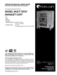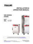
1
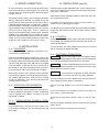
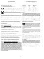
Quality Refrigeration OWNER’S MANUAL Instructions for the installation, operation and maintenance of Traulsen: Rethermalization Oven Reach-In Model TRT32 and Roll-In Model TRT32R This Traulsen unit is built to our highest quality standards. We build our Rethermalization Oven this way as a matter of pride. This philosophy has made Traulsen the leader in commercial refrigeration since 1938. We thank you for your choice and confidence in Traulsen equipment and we know you will receive many years of utility from this equipment. All Traulsen units are placed on a permanent record file with the service department. In the event of any future questions you may have, please refer to the model and serial number found on the name tag affixed to the unit. Should you need service, call us on our toll free number, 800-825-8220 between 7:30 am - 4:30 pm CST, Monday thru Friday. You may also log onto www.traulsen.com for further information. It is our pleasure to help and assist you in every possible way. INSTALLER COMPLETE THE FOLLOWING INFORMATION PRIOR TO UNIT INSTALLATION INITIAL START DATE: SERIAL NO. MODEL TYPE: COMPANY/INDIVIDUAL NAME: INSTALLER: FORM NUMBER TR35898 REV. 11/08 P/N 375-60302-00 TABLE OF CONTENTS I. THE SERIAL TAG II. RECEIPT INSPECTION III. INSTALLATION a-Packaging b-Electrical Requirements c-Installation Codes & Standards d-Location e-Electrical Connection IV. OPERATION a-Before First Use b-Oven Controls c-User Adjustable Parameters d-Alarms e-Testing The Oven f-Operating The Oven g-Shutdown h-Extended Shutdown V. MAINTENANCE a-Interior b-Exterior c-Door Gasket (s) d-Stainless Steel Care - Cleaning e-Preserving And Restoring f-Heat Tint g-Calibration Procedure VI. Wiring Diagram VII. Trouble Shooting Guide VIII. Service Assistance a-Service Information b-Spare Parts Information c-Warranty Registration IX. Warranties X. Service Parts List XI. Retherm & Holding Guide Page 1 Page 2 Page 2 Page 2 Page 2 Page 2 Page 2 Page 3 Page 3 Page 3 Page 3 Page 4 Page 4 Page 5 Page 5 Page 5 Page 5 Page 5 Page 5 Page 5 Page 6 Page 6 Page 7 Page 8 Page 8 Page 8 Page 8 Page 9 Page 10 `Page 11 I. THE SERIAL TAG Model Volts Serial Phase Watts Amps Cycle The serial tag is a permanently affixed label on which is recorded vital electrical data about your Traulsen product, as well as the model and serial number. This tag is located in the exterior back of the cabinet by the electrical connection. READING THE SERIAL TAG • Model = The model # of your Traulsen unit • Serial = The permanent ID# of your Traulsen unit • Volts = Voltage • Phase = Phase • Watts = Wattage • Amps = Amps • Cycle = Cycle • Agency Labels = Designates agency listings -1- II. RECEIPT INSPECTION III. INSTALLATION (cont’d) All Traulsen products are factory tested for performance and are free from defects when shipped. The utmost care has been taken in crating this product to protect against damage in transit. National Electrical Code (ANSI/NFPA No. 70 latest edition) available from the National Fire Protection Association, Batterymarch Park, Quincy, MA 02269 You should carefully inspect your unit for damage during delivery. If damage is detected, you should save all the crating materials and make note on the carrier’s Bill Of Lading describing the damage. A freight claim should be filed immediately. If damage is subsequently noted during or immediately after installation, contact our customer care team to file a freight claim. There is a fifteen (15) day limit to file freight damage with the carrier. Under no condition may a damaged unit be returned to Traulsen without first obtaining written permission (return authorization). You may contact Hobart/Traulsen customer care at 800-333-7447 to request a return or file a claim. III. INSTALLATION III. a - PACKAGING: Your unit is packed in a cardboard carton which in turn, is banded to a wooden pallet. Remove the banding material holding the carton to the pallet. Remove the cardboard carton and the plastic bag covering the cabinet and the banding material holding the cart to the skid. Metal pan slides and shelves are shipped under the cabinet, in between the casters (careful not to discard boxes with other packaging material). Remove items from boxes and install in the interior of cabinet. Most exterior stainless steel surfaces have a protective vinyl covering to prevent scratching during manufacturing, shipping and installation. After the unit is installed in place of application peel, remove and discard the covering from all surfaces. III. b - ELECTRICAL REQUIREMENTS: Verify that the power source matches the serial tag electrical data, before the connection is made. A dedicated circuit is required for all models. See page 1 for serial tag location and data. Vapor Removal from Cooking Equipment, (NFPA-96, latest edition) available from NFPA. In Canada, the Traulsen oven system must be installed in accordance with the following local codes: Canadian Electrical Code available from the Canadian Standards Association, 5060 Spectrum Way, Mississauga, Ontario, Canada L4W 5N6. III. d - LOCATION: For efficient cabinet operation, choose a location that will provide easy loading and unloading without interfering with the final assembly of food orders. The final location must allow adequate clearances for servicing and air circulation for proper operation. III. e - ELECTRICAL CONNECTION : WARNING Before connecting the oven to the power source, verify that the voltage and phase of the power source are identical to the voltage and phase information on the data plate. WARNING Electrical and grounding connections must comply with the applicable portions of the National Electrical code and/or other local electrical codes. WARNING Do not store or use gasoline or other flammable vapors or liquids in the vicinity of this or any other appliance. The cord and plug come with a proper strain relief to prevent unit from moving away from electrical connection. Refer to the wiring diagram in this manual for proper connection. At the circuit breaker, turn off power to the circuit to which the oven system is to be connected. Check that the oven power ON/OFF switch is in the OFF position. III. c - INSTALLATION CODES & STANDARDS: Connect the power cord from the oven system to the electrical In the United States, the Traulsen oven system must be installed in accordance with the following state and local codes: power source. At the circuit breaker, turn on power to the circuit. -2- IV. OPERATION IV. OPERATION (cont’d) IV. a - BEFORE FIRST USE: Thoroughly clean the oven before initial use. NOTE: Avoid splashing water into upper areas of the cabinet to prevent damage to electrical components or connections. NOTE: Never spray the unit with a hose. NOTE: Never use harsh chemicals or abrasive pads to clean the cabinet. Remove the interior side racks and the air tunnel from the cabinet. Adjustable Parameters • rth Lo • rth Hi • hld Lo • hld Hi • CAL OffSEt Default Value 1000 3500 1000 2500 00 Adjustment Ranges 1000 - 3500 1000 - 3500 1000 - 2500 1000 - 2500 -300 - +300 rth Lo This is the RETHERM temperature low limit. It sets the lowest possible limit for the RETHERM temperature. Adjustments during normal operation may not be made lower than this parameter setting. Wring out the cloth so it is only damp and not soaking wet. rth Hi This is the RETHERM temperature high limit. It sets the highest possible limit for the RETHERM temperature. Adjustments during normal operation may not be made higher than this parameter setting. Reassemble oven. NOTE: Take the interior side racks and the air tunnel from the cabinet. Use a mild soap and water solution to clean these items. IV. b - OVEN CONTROLS: The operating control is located in the top front panel. The control contains the following displays, knob or push button (from left to right): Some local codes require the use of a ventilation hood for equipment operating in excess of 2500 degrees F. Many will allow operation of Rethermalization ovens at lower temperatures. Please modify this parameter if needed to meet local codes. hld Lo This is the HOLD temperature low limit. It sets the lowest possible limit for the HOLD temperature. Adjustments during normal operation may not be made lower than this parameter setting. TIME (IN MINUTES) - Displays set time. RETHERM TEMP - Displays set Retherm Temperature. HOLD TEMP - Displays set Hold Temperature. CABINET TEMP (PROGRAM #) - Displays interior temperature, displays programming number in programming mode. ADJ/SET - Knob allows Adjustment and Setting changes. START - Button will start the operation/pre-set settings. IV. c - USER ADJUSTABLE PARAMETERS: The user’s parameter set menu is entered by turning the oven on while pushing the START button. The START button must remain depressed for 4 seconds after power has been applied. The user’s parameter settings menu is then active. There are 5 adjustable parameters. Rotate ADJ/SET to change the currently displayed parameter. Push ADJ/SET to advance to the next parameter. Push START to accept and save the current parameter settings and exit the parameter set menu. Normal oven operation is resumed with the new settings. -3- hld Hi This is the HOLD temperature high limit. It sets the highest possible limit for the HOLD temperature. Adjustments during normal operation may not be made higher than this parameter setting. CAL OFFSet This parameter is a calibration offset and is used in conjunction with a precision thermometer. The cal offset may be set from -30 to 30 to calibrate the oven temperature regulation and display. IV. d - ALARMS: The oven reports an over temperature condition any time the oven temperature reaches 400° or higher. IV. OPERATION (cont’d) IV. OPERATION (cont’d) When this condition exists the oven will sound an audible alarm by emitting a triple beep (three quick short beeps) every 2 seconds and it will flash the message “Err too Hot” on the display to alert nearby staff. The audible alarm may be temporarily canceled FOR 3 MINUTES by pushing ADJ/SET. After 3 minutes have expired the oven will begin beeping again. The error message on the display cannot be canceled. The proper action when this alarm is present is to turn the oven off and call for service. User programming of the 9 most used cycle parameters. Fast recall and cycle start of the pre-programmed cycle parameters. Very fast recall and cycle start of pre-programmed cycle #1 parameters. IV. e - TESTING THE OVEN: Before using the oven for the first time, verify that the oven operates normally. Check that the oven is connected to the correct power source. Turn the oven ON at the power switch. Use the controls to set the HOLDING TEMPERATURE to 1400F. Check that the oven circulating fans are running. Check that the heaters ON indicator is lit. Check that the oven is warming to the displayed holding temperature. NOTE: The cooling fans may not operate when the oven is first turned on. The cooling fans operate only when the thermostat to which they are connected requires it. Set the TIME to 2 hours, Set the RETHERM TEMP to 2500, push the START BUTTON, check the interior rear of the oven cavity to determine that the oven is heating. Push the ADJ/SET knob to cancel the cycle, set the TIME to 0, set the HOLD TEMP to 2500F, push the START BUTTON. Check that the RETHERM TEMP display has been blanked and the HOLD TEMP display is lighted. Check the interior rear of the oven to ensure that the oven is heating. If all the functions perform satisfactory, the oven is ready for operation. IV. f - OPERATING THE OVEN: Main Features Flexibility-Manual setting of the parameters RETHERM TIME, HOLD TEMP and RETHERM TEMP. Quick cycle start-Press START at any time during parameter entry to execute a cycle with the existing parameters displayed. The only exception to this is during programming of the stored settings (1 – 9). Quick cycle abort-Press the ADJ/SET knob at any time during the retherm cycle to return to the Idle State. -4- Manual Setting Features From the IDLE STATE (TIME is blinking) rotate the ADJ/ SET knob to adjust the retherm time. Press START to accept the currently displayed settings and begin the cycle or press ADJ/SET to set the currently displayed time and advance to the RETHERM TEMP setting. RETHERM is blinking. Rotate the ADJ/SET knob to adjust the retherm temperature. Press START to begin the cycle or press ADJ/SET to set the retherm temperature and advance to the HOLD TEMP setting. HOLD is blinking. Rotate ADJ/SET to adjust the hold temperature. Press START to execute the cycle or press ADJ/SET to re-adjust the three parameters. After a cycle is started press ADJ/SET at any time to abort the cycle and return to idle. Pre-Programmed Cycle Feature From the IDLE STATE (Time Blinking) press and hold ADJ/SET for 3 seconds. TIME no longer blinks. The current temperature display TEMP displays “P-1” and is blinking. TIME, RETHERM and HOLD display the parameters pre programmed for AUTO CYCLE #1. Press START to execute a retherm cycle with these parameters or rotate the ADJ/SET knob to select one of the other pre-programmed cycle settings (0–9) then press START . After a cycle is started press ADJ/SET at any time to abort the cycle and return to idle. Programming The Pre-Programmed Cycles From the IDLE STATE (Time Blinking) press and hold ADJ/SET for 3 seconds. TIME no longer blinks. The current temperature display TEMP displays “P-1” and is blinking. If necessary rotate ADJ/SET to the desired pre-programmed cycle “P-x”. Press and hold ADJ/SET for 3 seconds. P-x no longer blinks and TIME is blinking. Rotate ADJ/SET to adjust the retherm time and press ADJ/SET to accept the retherm time. RETHERM is blinking. Rotate ADJ/SET to adjust the retherm temperature and press ADJ/SET to accept the retherm temperature. HOLD is blinking. Rotate ADJ/SET to adjust the hold temperature and press ADJ/SET to accept the hold temperature. P-x has been updated to the currently displayed settings and P-x is again blinking. To program another location rotate ADJ/SET to the desired cycle # then press and hold ADJ/SET for 3 seconds. To return to IDLE press and release ADJ/SET. To start a cycle with the currently displayed settings press START. Fast cycle Start Using Pre-programmed Setting #1 Press ADJ/SET. While holding ADJ/SET press START. (see page 11 for Retherm & Holding Guide) IV. OPERATION (cont’d) V. MAINTENANCE (cont’d) IV. g - SHUTDOWN: Turn the Power ON/OFF Switch to OFF position. IV. h - EXTENDED SHUTDOWN: Perform the following procedure to shut down the oven for an extended period of time. NOTE: Leave the compartment door (s) slightly open (unlatched) when the unit is not in use. Keeping the gasket under pressure when the unit is not in use can cause a permanent deformation of the gasket and reduce its serviceable life. V. d - STAINLESS STEEL CARE - CLEANING: Perform shutdown procedure. Unplug the unit. Thoroughly clean the oven according to the cleaning procedures in this manual. Leave the door (s) slightly open to allow ventilation and preservation of the gasket (s). V. MAINTENANCE V. a - INTERIOR: Wash the inside of the compartment with a solution of mild detergent and warm water. Rinse thoroughly with warm water. Stainless steel contains 70-80% iron, which will rust if not properly maintained. It also contains 12-30% chromium, which forms an invisible passive, protective film that shields against corrosion. If the film remains intact, the stainless steel will remain intact. However, if the film is damaged, the stainless steel can break down and rust. To prevent stainless steel breakdown, follow these steps: Never use any metal tools. Scrappers, files, wire brushes or scouring pads (except for stainless steel scouring pads), will mar the surface. Never use steel wool, which will leave behind particles that rust. Wipe dry. This should be performed based upon a schedule predetermined for your operation. Never use acid based or chloride-containing cleaning solutions, which will break down the protective film. Never rub in a circular motion. V. b - EXTERIOR: Never leave any food products or salt on the surface. Many foods are acidic. Salt contains chloride. V. c - Door Gasket (s): For routine cleaning, use warm water, mild soap or detergent and a sponge or soft cloth. Refer to “Stainless Steel Care-Cleaning”. At least once a week, thoroughly clean the gasket sealing surfaced of the oven door (s) to remove food acids; this action will ensure maximum gasket life. NOTE: Do not use any solvents or sharp instruments to clean the gasket (s). Wash the gasket (s) with a cloth moistened with a solution of mild detergent and warm water. Rinse with a fresh cloth moistened in warm water to remove all traces of detergent. For heavy-duty cleaning, use warm water a de greaser and a plastic, stainless steel or scotch-brite pad. Always rinse thoroughly. Always rub gently in the direction of the steel grain. V. e - PRESERVING AND RESTORING: Special stainless steel polishing cleaners can preserve and restore the protective film. Preserve the life of stainless steel with a regular application of a high quality stainless steel polishing cleaner as a final step to daily cleaning. Wipe dry with a clean dry cloth. Never apply food oils or petroleum lubricants directly to the gasket (s); petroleum-based solvents and lubricants will reduce gasket life. Leaking and/or damaged or gaskets (s) cause inefficient and unsatisfactory operation of the unit. Replace any door gasket (s) that are damage or deformed. -5- If signs of breakdown appear, restore the stainless steel surface. First, thoroughly clean, rinse and dry surface. Then, on a daily basis, apply a high-quality stainless steel polish according to manufacturer’s instructions. V. MAINTENANCE (cont’d) V. f - HEAT TINT: Darkened areas, called “heat tint”, may appear on stainless steel exposed to excessive heat, which causes the protective film to thicken. It is unsightly but is not a sign of permanent damage. To remove heat tint, follow the routine cleaning procedure. Stubborn heat tint will require heavy-duty cleaning. V. g - CALIBRATION PROCEDURE: All units are tested and calibrated to run precisely as designed prior to shipment. However, if over time there becomes a need to calibrate or adjust the sensors please utilize the procedure noted below. First, set the CAL OFF Set parameter to 0 using the procedure described under User Adjustable Parameters. Place a precision thermometer inside the oven’s cavity. Turn on the oven and adjust the HOLD Temperature to 160 Degrees. When the oven has reached the set temperature wait another 10 minutes for temperatures to become homogenous inside the oven, read the precision thermometer and compare it to the oven’s temperature display. If the oven’s current temperature display is greater than the precision thermometer reading, the CAL OFF Set must be set negative (-) the number of degrees that the oven display is higher than the precision thermometer reading. If the oven’s current temperature display is lower, the CAL OFF Set must be set positive the number of degrees that the oven display is lower than the precision thermometer reading. EXAMPLE The oven’s current temperature display after reaching 160 and a 10 minute wait is 161. The precision thermometer reading is 164. The CAL OFF Set parameter should be set to 3. EXAMPLE The oven’s current temperature display after reaching 160 and a 10 minute wait is 160. The precision thermometer reading is 156. The CAL OFF Set parameter should be set to -4. -6- -7- A B C D COOLING FAN 2 COOLING FAN 1 GREEN BLACK WHITE IN LINE TAP 5 IN LINE TAP COOLING FAN THERMOSTAT 12V CLASS II TRANSFORMER YELLOW BLACK IN LINE TAP YELLOW L1 BLACK L2 POWER SWITCH REAR VIEW DISTRIBUTION BLOCK 4 4 J2-1 J1-1 $ 3 NC 2 J4 $ = .125" FASTON, 2 TOTAL NO # CONTROL AND DISPLAY BOARD # # $ 1 C START SWITCH FUSE 3A FUSE 3A 1 # 1 2 3 4 # 2 3 AMP 640250-4 12VDC 4 HEATER RELAY HI - LIMIT 1 2 3 4 3 L2 3 L1 CONTACTOR COIL+ COIL- 5 .1uF/600V 1 2 AMP 640250-2 1 2 TT+ RED YELLOW CONTACT PINS AMP 640252-1 or 770476-1 QTY = 4 QTY = 2 J8 J3 BLOWER FAN TERMINAL BLOCK # = .25" FASTON, 6 TOTAL # + 160 OHM HEATING ELEMENT 2 SHAFT ENCODER BLOWER FAN HEATING ELEMENT 1 Document Number 379-60486-00 Thursday, July 10, 2008 Size B Date: 1 Sheet RT-32 WIRING DIAGRAM, 208-240v, 10, 60Hz 4401 Blue Mound Rd., Fort Worth, TX 76106 Traulsen & Company K TYPE THERMOCOUPLE, GROUNDED TERMINAL BLOCK BLOWER FAN HEATING ELEMENT Title 6 CONDUCTOR RIBBON BLOWER FAN HEATING ELEMENT 2 1 of 12 Rev 1 A B C D VI. WIRING DIAGRAM Refer to the wiring diagram below for any service work performed by a qualified technician. VII. TROUBLE SHOOTING GUIDE PROBLEM POSSIBLE CAUSE 1. Oven NOT operating. a. Power ON/OFF switch is not on? b. Oven is not plugged into power source. c. Fuse is blown. 2. Oven Compartment is NOT heating and a. Defective connection. blower motor is operating with power switch on. b. Defective wiring. 3. Oven is warming but cooling fans are NOT operating. a. b. c. d. Oven is below 1500F. Defective connection or wiring. Defective Fan. Defective Temperature Probe. 4. Oven compartment IS NOT heating and blow- a. Oven is below 400F. b. Missing or defective thermocouple. er motor IS operating with power switch ON. c. Defective High-Limit Thermostat. d. Defective Heating Element. VIII. SERVICE ASSISTANCE VIII. a - SERVICE INFORMATION: If after checking the items in the trouble shooting guide, and the unit is still not operating properly, please contact an authorized Traulsen service agent. You may obtain the name of a service agent from the Tech Service page of our web site: www.traulsen.com. If service is not satisfactory, please contact our in-house service department at: Traulsen 4401 Blue Mound Road Fort Worth, TX 76106 (800) 825-8220 VIII. b - SPARE PARTS INFORMATION: To purchase replacement parts or to speak to service support for Traulsen and most Hobart Refrigeration units please contact our Ft. Worth facility by phone at 800-825-8220 or fax to 817-740-6748 (parts) or 817-740-6757 (service). To source parts locally follow instructions below for nearest location: 1. Log onto www.traulsen.com 2. Select Service Directory (top of screen) 3. Select Locate Parts (left side of screen) 4. Click on State desired To source service support locally follow instructions below for nearest authorized service agent: 1. Log onto www.traulsen.com 2. Select Service Directory (top of screen) 4. Click on State desired VIII. c - WARRANTY REGISTRATION: The warranties for your new Traulsen unit may be registered with us by contacting our Ft. Worth facility by phone at 800825-8220 or you may register on line: 1. Log onto www.traulsen.com 2. Select Service Directory (top of screen) 3. Select Warranty Registration Form (left side of screen) 4. Fill out information requested 5. Select Submit to complete unit warranty registration Note: When calling for spare parts or service support, please make sure you have model and serial number of unit available. -8- IX. WARRANTIES STANDARD DOMESTIC WARRANTY TRAULSEN warrants new equipment to the original purchaser, when installed within the United States against defective material and workmanship for one (1) year from the date of original installation. Under this warranty, TRAULSEN, will repair or replace, at its option, including service and labor, all parts found to be defective and subject to this warranty. Lifetime parts warranty on door hinges and door latch. This warranty does not apply to damage resulting from fire, water, burglary, accident, abuse, misuse, transit, acts of God, terrorism, attempted repairs, improper installation by unauthorized persons, and will not apply to food loss. THERE ARE NO ORAL, STATUTORY OR IMPLIED WARRANTIES APPLICABLE TO TRAULSEN, INCLUDING BUT NOT LIMITED TO, ANY IMPLIED WARRANTY OF MERCHANTABILITY OR FITNESS FOR ANY PARTICULAR PURPOSE WHICH EXTEND BEYOND THE DESCRIPTION ON THE FACE HEREOF. TRAULSEN SHALL HAVE NO OBLIGATION OR LIABILITY FOR CONSEQUENTIAL OR SPECIAL DAMAGES, GROWING OUT OF OR WITH RESPECT TO THE EQUIPMENT OR ITS SALE, OPERATION OR USE, AND TRAULSEN NEITHER ASSUMES NOR AUTHORIZES ANYONE ELSE TO ASSUME FOR IT ANY OBLIGATION OR LIABILITY IN CONNECTION WITH THE EQUIPMENT OR ITS SALE, OPERATION OR USE OTHER THAN AS STATED HEREIN. INTERNATIONAL COMMERCIAL WARRANTY (for Canadian warranties see domestic US warranty) TRAULSEN warrants to the original purchaser, new equipment to be manufactured and sold by, it to be free from defects in material and workmanship under normal use and service for a period of one (1) year from date of shipment. Under this warranty, TRAULSEN will reimburse the purchaser for the replacement of any part of said equipment, which then proves to be defective. This warranty does not apply to damage resulting from fire, water, burglary, accident, abuse, misuse, transit, acts of God, terrorism, attempted repairs, improper installation by unauthorized persons, and will not apply to food loss. TRAULSEN’S standard warranty does not apply to Export Sales. Rather, for a period of one (1) year from date of original installation not to exceed Fifteen (15) months from date of shipment from factory, TRAULSEN: will replace, F.O.B. factory, any defective parts normally subject to warranty. will not cover the cost of packing, freight or labor such costs being the sole responsibility of the dealer/end user. THIS WARRANTY IS IN LIEU OF ALL OTHER WARRANTIES EITHER EXPRESSED OR IMPLIED AND CONSTITUTES TRAULSEN’S FULL OBLIGATION AND LIABILITY. WARRANTIES NOT AVAILABLE ON REMOTE MODELS. -9- X. SERVICE PARTS LIST DESCRIPTION PART NUMBER BLOCK TERMINAL (INTERNAL DISTRIBUTION) AD-206-2000-0 BLOCK, TERMINAL (POWER CONNECT) AD-206-1000-0 BOLT, RETAINING RACK (PACK OF 4) WP-305 CONTACTOR, 3POLE-50AMP(208/240V) AD-260-6000-COR CORD, POWER 208/240V AD-161-3000-0 ELEMENT, OVEN 208/240V/1900W AD-280-1000-0 FAN, COOLING 208/240V AD-305-2000-0 FUSE, 3 AMP AD-207-0000-0 GASKET, DOOR (PER FOOT) WP-302 GRATE, RETURN AIR AD-266-0000-0 GUARD, FAN AD-253-0000-0 CASTER, RIGID WP-114-6R CASTER, SWIVEL WITH BRAKES WP-114-6S SHELF, WIRE WP-019 HANDLE, SIDE AD-307-1000-0 HINGE, DOOR AD-306-1000-0 HOLDER, FUSE AD-210-0000-0 HOLDER, PROBE (TEMPERATURE) 1/4” AD-150-1 LATCH, DOOR CHROME WP-215 MOTOR, BLOWER (208/240V) AD-301-2000-0 RACK, MEAT (INSERT FOR SHEET PAN 18”X26”) AD-400 STRAIN RELIEF, POWER CORD AD-252-2000-00 SUPPRESSER, ORANGE (W/RESISTOR) AD-135-0000-0 SWITCH, ROCKER AD-213 THERMOSTAT, COOLING FAN W/BRACKET AD-251-0000-0 THERMOSTAT, HIGH-LIMIT AD-241-0000-0 VENT, SCREEN AD-253-10000-0 PRINTED CIRCUIT BOARD ASSEMBLY 950-60420-00 ENCODER 336-10148-00 TRANSFORMER 337-60169-03 RELAY 336-10149-00 PUSH BUTTON 337-60425-00 CONTROL KNOB 336-10147-01 STAND OFFS FOR BOARD MOUNTING (6-6/32X.250) 351-60059-250 -10- XI. Retherm & Holding Guide Traulsen’s Guide to Retherm & Holding The below information is intended for use as a general reference only when using the Traulsen retherm oven. Please note that as products vary, as well as other elements such as altitude, so shall actual cooking times and temperatures. These should be adjusted as needed based upon your actual experience, and finished product temperatures should be verified manually prior to serving in order to insure food safety. Cook Time Cook Temp Product Details/Weight Boneless Ribeye USDA #112A, 12 lbs. 3 hrs 225°F Steamship Round USDA #160, 60 lbs. 10 hrs 225°F Boneless Strip Loin USDA #180, 12 lbs. 3 hrs 225°F Top Sirloin Butt USDA #184, 12-14 lbs. 3 hrs 225°F Prime Rib Top Round Bottom Round Whole Tenderloin USDA #109, 20 lbs. USDA #168, 18-20 lbs. USDA #170, 20 lbs. USDA #190, 4-6 lbs. Beef Short Ribs 10 lbs. Beef Back Ribs 30 lbs. Cubed Steaks Beef Stew Corned Beef Frozen Burgers Fresh Ham 2 10 lbs. 4-1/2-5 hrs 5 hrs 2-1/2 hrs 4 hrs 225°F 4 hrs min 140°F 45 min 225°F Pork Spare Ribs 30 lbs. 6 hrs 4 hrs 250°F Fresh Sausages 10 lbs. 2 hrs 225°F Roast Suckling Pig 30 lbs. Bacon Chicken Wings 10 lbs. 1-3/4 hrs 250°F 10 lbs. 45 min 40 min 350°F 6 hrs 8 pcs. per 3-1/2 lb. bird 2-1/4 hrs 250°F Rottisserie Chicken 2-3/4 lbs. 2-1/2 hrs 375°F Whole Chickens 3-1/4 lbs. Whole Turkeys 20 lbs. Roast Duckling 4 lbs. Turkey Breast7 Rack of Lamb Braised Lamb Shanks Fish Filets Sheet Cakes Kaiser Rolls Italian Bread Cookies 10 lbs. 2-1/2 hrs 5 hrs 4 hrs 350°F 4 hrs 250°F 18” x 26” 1-1/4 hrs 300°F Various Types 20-35 min 40 min 350°F 10 lbs. 4-6 oz. 3-1/2 hrs 40 min 35 min Clear Soups 12” x 20” Pans 3 hrs 250°F 12” x 20” Pans 1-1/4 hr 350°F 1 Quart Dry 3 hrs 250°F Frozen Pizzas 18” diameter Rice 1 Quart Dry Baked Potatoes Frozen Entrees 40 min 2 hrs 1 hr max 5 hrs max 1 hr 3 hrs max 3 hrs max n/a n/a Overnight 130°F 2 per shelf on 4 shelves 2 per shelf on 4 shelves 130°F 1 per shelf on 2 shelves 130°F 2 per shelf on 4 shelves 130°F 3 per shelf on 6 shelves 130°F 4 per shelf on 8 shelves 135°F 3 per shelf on 4 shelves 165°F 1 per shelf on 6 shelves 180°F 1 per shelf on 6 shelves 175°F 4 per shelf on 6 shelves 140°F 1 per shelf on 6 shelves 165°F 2 per shelf on 6 shelves 165°F 24 per shelf on 14 shelves 165°F 4 per shelf on 4 shelves 135°F 2 per shelf on 4 shelves 175°F3 6 per shelf on 8 shelves 175°F 52 per shelf on 6 shelves 175°F3 160°F 5 per shelf on 6 shelves 52 per shelf on 8 shelves 150°F 165°F 80 per shelf on 8 shelves 150°F 170°F n/a 150°F 160°F 170°F 160°F 160°F 140°F 160°F n/a n/a n/a n/a n/a n/a 170°F 170°F6 2 per shelf on 4 shelves 160°F3 170°F3 140°F 3 per shelf on 4 shelves 6 per shelf on 6 shelves 14 per shelf on 8 shelves 1 per shelf on 8 shelves 190°F 1 per shelf on 8 shelves 160°F 190°F 190°F n/a n/a 32 per shelf on 8 shelves 15 per shelf on 8 shelves 6 per shelf on 8 shelves 24 per shelf on 14 shelves 3 per shelf on 8 shelves n/a 200°F 160°F 6 per shelf on 6 shelves 180°F3 170°F 150°F 8 per shelf on 6 shelves 6 per shelf on 6 shelves 170°F3 175°F 18 hrs max 33 per shelf on 14 shelves 5 160°F 160°F Overnight 3 per shelf on 6 shelves 1 per shelf on 4 shelves 2 hrs max 1-1/2 hrs 135°F 170°F4 n/a n/a 250°F 160°F n/a n/a 350°F 160°F 160°F n/a 350°F 160°F 4 hrs min 4 hrs max 350°F 160°F n/a 5 hrs max 325°F 160°F 160°F 1 hr max 350°F 150°F 3 hrs min n/a 225°F Various Types, 9” dia. 30 min 5 hrs max 250°F Pies with Top Crust Dinner Rolls 1-1/4 hrs 5 hrs max 250°F 1-1/2 hrs 160°F 4 hrs 250°F 160°F 150°F 4 hrs 3 hrs 250°F 160°F 150°F 4 hrs 350°F 140°F 4 hrs min 4 hrs max 250°F Chicken Pieces 155°F 6 hrs1 255°F 140°F 4 hrs min 4 hrs 250°F 140°F 140°F 3 hrs min 250°F 140°F 2 hrs min 4 hrs min 250°F 4 hrs Pre-Cooked Sausage 4 hrs 225°F USDA #422, 10 lbs. 4 hrs 8 hrs 225°F 4-5 oz. 12 lbs. 4 hrs min 225°F 225°F 12 lbs. 4 hrs min 225°F 4 hrs 4 hrs 135°F 140°F 10 lbs. (stew meat) 12 lbs. 140°F 4 hrs min 225°F 5 hrs Max. Internal Loading Guidelines Temp 2 per shelf on 4 shelves 225°F 4 hrs Cooked Cured Ham Pork Back Ribs 5 hrs Hold Time Hold Temp 42 per shelf on 8 shelves 1 per shelf on 6 shelves 175°F6 2 per shelf on 8 shelves 160°F 1 per shelf on 8 shelves 165°F 30 per shelf on 8 shelves 2 per shelf on 8 shelves NOTE: For preheating please allow 1-minute for every ten degrees needed above current displayed cabinet temperature. 1= Overnight 2= Short Shank #402 or Bone Rolled Tied #402B 3= Internal holding temp 150°F 5= Internal holding temp 140°F 6= Internal holding temp 160°F -11- 4= Internal holding temp 155°F 7= Bone In © Traulsen 2008 - All Rights Reserved. Revised 10/08 Notes Notes Notes HOURS OF OPERATION: Monday thru Friday 7:30 am - 4:30 pm CST Quality Refrigeration Traulsen 4401 Blue Moud Road Fort Worth, TX 76106 Phone (800) 825-8220 Fax (817) 740-6757 Website: www.traulsen.com © 2008 Traulsen - All Rights Reserved