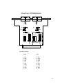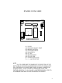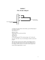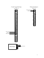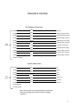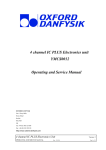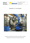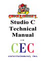
1
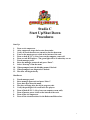
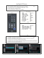
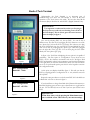
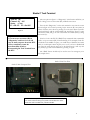
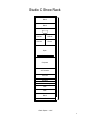
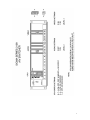
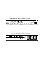
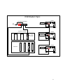
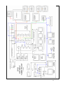
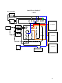
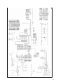
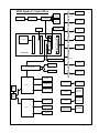
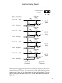
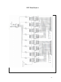
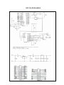
Studio C
Technical
Manual
1-7-00
Studio C
Start Up/Shut Down
Procedures
Start Up:
1.
2.
3.
4.
5.
6.
7.
8.
9.
10.
11.
12.
Turn on air compressor.
After compressor stops, drain water from tanks.
Verify all circuit breakers are turned on for the showroom.
Turn on the master power switch at the bottom of the rack.
Turn on both D.T.U.’s (Gray boxes on the computer room wall.
Turn on each DVD player…The green light will be lit when they are on.
Touch manager panel.
Enter the manager password and press “Enter”.
Select “Start-up” from the menu.
When prompted enter the birthday names if desired.
When prompted, run diagnostics if desired.
The show will begin shortly.
Shut Down:
1.
2.
3.
4.
5.
6.
7.
8.
9.
Touch manager panel.
Enter manager password and press “Enter”.
Press shut down from the menu.
The show will stop after the skit in progress ends.
Verify the park light is lit on all laser disc players.
Turn off both D.T.U.’s (Grey boxes on computer room wall).
Turn off master power switch at the bottom of the rack.
Turn off the air compressor.
Turn off the circuit breakers for the Roboscans/Robocolors.
1
Installing the DVD players
1.
2.
3.
4.
5.
Make sure there are no discs in the players.
Press and hold the MENU button on the remote for 5 seconds.
Use the down arrow to cycle through the settings (Fig 2 / Fig 3).
Use the right arrow to change the value.
Use the up and down to select the item to change.
Step 1
Correct Settings
Remote
Fig 2
Fig 3
1.
2.
3.
4.
5.
6.
7.
Press MENU 1 time (Exits the screen menu).
Step 2
Press MENU 1 time (Enters the menu selection).
Press enter to select INITIAL (Fig 4) (This screen will display if no discs are in the player).
Use the down arrow to select B.G. COLOR, press enter (Fig 5).
Use the down arrow to select the green square and use the left arrow to turn it all the way down (Fig 6).
Use the down arrow to select the blue square and use the left arrow to turn it all the way down (Fig 6).
Press Enter. You are now ready to insert the dis cs.
Fig 4
Fig 5
Fig 6
2
Studio C Tech Terminal
Understanding the Tech Terminal is an important part of
troubleshooting your show. We will attempt to cover all the basic
operations of the Tech Term in this article. We have also listed all the
movements (Bits) in both the #1 and #2 DTUs (Digital Terminal Units).
Important Note:
It is important to understand that when you first plug in
the Tech Term you will only see a flashing cursor on the on
the LCD display. This is normal, press the menu button to
show the display in figure 1.
Let’s start by selecting DTU #1, the top DTU. You can do this 2
different ways. The first way is by plugging the Tech Term into one of the
two “phone type” jacks at the front of your stage. The other way is to plug
the Tech Term directly into the gray DTU box located behind the stage.
This can be done by, unplugging the “phone type” cable that is plugged
into the right side of the gray box. You can then plug the Tech Term
directly into that “phone type” plug.
Figure 1
DTU Configuration
Bank #01 <1-64>
Figure 2
DTU Configuration
Bank #02 <65-128>
Figure 3
In figure 1, the Tech Term is displaying the two options it is capable of
performing. The first option is “Configuration”. Every show has two
DTUs, one for the character movements and one for the lights. Both
DTUs are identical, in order for the computer to send the right information
to the right DTU we must first tell the DTUs which one is #1 and which
one is #2. To perform this option, press the #1 on the keypad to enter into
the configuration mode.
At this point your display should like figure 2. This tells you that the
DTU you are plugged into is configured as #1 <1-64>, which is correct for
the top DTU.
Repeat the same procedures to set the bottom DTU #2. It should be set
to Bank #02 <65-128> as shown in figure 3.
If you should have to change from Bank #01 (Character Movements) to
Bank #02 (Lighting) press the arrow up or down button to toggle between
the two. You should only have to do this if you have just received a new
DTU.
Important Note:
When done, always exit by pressing the Menu button until
you see a blank screen. This will save your current settings.
3
Studio C Tech Terminal
Arm out (R)
Channel : 01 Off
Status : Clear
F1 = BL/CL F2 = On/Off
Figure 4
Important Note:
If you turn on a movement (Bit) in
“Diagnostics” and leave it on, it will
stay on until you power down the DTU.
Always remember to turn the
movement (Bit) off before
disconnecting the Tech Terminal from
the DTU.
The next option in figure 1 is “Diagnostics”. This function will allow you
to do 2 things, turn on a movement (Bit) or Blind a movement.
Press the #2 “Diagnostics” on the tech terminal to enter into the screen
shown in figure 4. Let’s start by turning on the “Arm out (R)” movement on
Chuck E Cheese, this is done by pressing F2 on the Tech Term. Chuck E’s
arm should move and the corresponding led should light. Press F2 again
and the bit (LED) will go off. You select other movements (Bits) by using
the arrow keys.
Now let’s look at the BL/CL (Blind/Clear) command. This command is
used to stop a movement (Bit) from functioning. If for example, Chuck E’s
arm breaks in the middle of a party, you would want to blind that movement
until you could repair it when the party was over. If you leave it blinded and
exit using the menu button until you see the blank screen, it will stay that
way until you go back in and unblind it by pressing F1 again.
The “Blind” feature should only be used in case of an emergency as in
the example above.
Studio C DTU Fan Filter
Studio C Main Computer Filter
You should clean your Computer and DTU fan filters once every
two weeks. This will keep your system cool and dust free. In the
future this will be included on your PM calendar.
4
Studio C Bit Chart
DTU #1
DTU #2
1 ARM OUT
33 BIRD MOUTH
1 CEC RED FLOODS
33 HOUSE LT DIM
2 ARM SWING
34 BIRD BOW
2 CEC GREEN FLOODS
34
3 ELBOW UP
35 BIRD TURN
3 CEC BLUE FLOODS
35
4 WRIST TURN
36 BIRD WINGS
4 CEC AMBER FLOODS
36
5 WAVE
37 BIRD SPARE
5 BS RED FLOODS (NOT USED)
37
6 ARM OUT
38 BIRD SPARE
6 BS GREEN FLOODS (NOT USED)
38
7 ARM SWING
39 BIRD SPARE
7 BS AMBER FLOODS (NOT USED)
39
8 ELBOW UP
40 PHONE SWING
8 SPARE 1-8
40
9 WRIST TURN
41 PHONE SPARE
9 CLOCK NEON
41
10 WAVE
42 PHONE SPARE
10 CLOCK FORWARD
42
11 LEFT ARM FORWARD
43
11 CLOCK REVERSE
43
12 BODY FORWARD
44 CURTAIN OPEN
12 STROBE
44
13 BODY LEFT SIDE BEND
45 CURTAIN CLOSE
13 CITY LIGHTS
45
14 BODY RIGHT
46
14 DESK PANEL BLUE (INNER)
46
15 TORSO TWIST RIGHT
47
15 DESK PANEL GREEN (MIDDLE)
47
16 TORSO TWIST LEFT
48
16 DESK PANEL RED (OUTER)
48
17 RIGHT ARM FORWARD
49 PHONE SPARE
17 PHONE HANDSET LTS
49
18 HEAD TURN LEFT
50
18 PHONE DIAL LTS
50
19 HEAD TURN RIGHT
51
19 ON AIR SHOW
51
20 HEAD UP
52
20 APPLAUSE SIGN
52
21 MOUTH
53
21 MONITOR CHASE LIGHTS
53
22 HEAD TILT RIGHT
54
22 MONITOR PINK NEON (INNER)
54
23 HEAD TILT LEFT
55
23 MONITOR BLUE NEON (MIDDLE)
55
24 EYE BLINK DOWN
56
24 MONITOR GREEN NEON (OUTER)
56
25 EYE BLINK UP
57
25
57
26 NOSE
58
26 GEMINI-WARP
58
27 EYE TURN LEFT
59
27 CEC SPOT
59
28 EYE TURN RIGHT
60
28 BIRD SPOT
60
29 EYEBOWS UP
61
29 LIVE FLOODS
61
30 EYEBROWS DOWN
62
30 AMBER ROOM FLOODS
62
31 EARS
63
31 PINK ROOM FLOODS
63
32 FOOT TAP
64
32 BLUE ROOM FLOODS
64
5
Studio C Show Rack
Blank
Blank
Tote Monitor
DVD #1
DVD #2
DVD #3
Phone
Open
Keyboard
Computer
A/V Switcher
Karaoke
COP
Symetrix
421 Leveler
BVS Master Keyer
AMP
AMP
Blank
Power Switch
1 Rack Space = 1-3/4 "
6
7
MASTER SYMETRIX 571 SPL SETTINGS
RATIO
SENSE : OUTPUT
1:1
PAGE OVER MUSIC
AVERAGING TIME
OUTPUT
GAIN TRIM
FK
MODE
PAGE SENSE
MIC. MIC. 1 MIC.2
5%
CW
30
1.2
NOTE: SET AT ABOUT
15 SECONDS
75% 75%
CW CW
NOTE: DIABLED ONCE
JUMPERS REMOVED
0
INDICATOR L.E.D.'S
MIN
MAX
SET DURING
CALIBARATION
MIN 75DB MAX 95DB
OPTION SWITCHES
ALL OFF
SLAVE SYMETRIX 571 S SETTINGS
PAGE OVER MUSIC
NOTE: GAMEROOM AUDIO SHOULD BE
SET AT 75DB AND SHOULD NOT BE
CHANGED
0
REAR VIEW OF MASTER SYMETRIX
REMOTE
GAIN TRIM
HOUSE
PAGE
IN
+
-
OUTPUT
GND
TB2
7
6
5
GND
4
3
2
1
TB1
10
9
+
8
7
6
5
4
FORMAT
PAGE
MUSIC
MUSIC
IN
GND +
-
GND
-
3
2
1
NOTE :
SHOULD BE
IN MUSIC
Jumper
sence mic 1
sence mic 2
page mic
REAR VIEW OF SLAVE SYMETRIX
OUTPUT
TB1
GND +
-
10
8
9
7
HOUSE
PAGE
IN
GND +
-
MUSIC
IN
GND +
-
6
3
5
4
2
FORMAT
PAGE
MUSIC
1
NOTE :
SHOULD BE
IN MUSIC
8
Gameroom Amp PIP-RPA Module
Crown Amp
RPA
CH2
CH1
+
-
+
A
70V
70V
CH 2
OUT
CH 1
OUT
LINE
MIC
LINE
LINE
C
TIE
RMTB
-
+
D
RMTA
RMTC
-
RMTD
+10V
+
AUDIO BUS
(NOT USED)
B
A OUTPUT
A/B SWITCH
OUTPUT 2
A/V SWITCHER
DIP Switch settings :
1 - ON
2 - ON
3 - ON
4 - OFF
5 - OFF
6 - OFF
7 - OFF
8 - OFF
Kiddie
70V
Skills
70V
9
R140
R240
Show Room PIP-BEQ Module
BY
BY
FUL
SUB
NORM
ON
1 2 3 4 56 7 88 910
1 2 3 4 5 6 7 88 9 10
S100
This section
is not used
ON
ON
ON
ON
1 2 3 4 56 7 8 910
1 2 3 4 5 6 7 88 910
S200
EQ
S101
NORM
EQ
S201
Dip switch settings:
S200
1 - ON
2 - OFF
3 - OFF
4 - ON
5 - ON
6 - ON
7 - OFF
8 - OFF
9 - ON
10 - ON
S201
1 - ON
2 - OFF
3 - OFF
4 - OFF
5 - N/A
6 - OFF
7 - OFF
8 - OFF
9 - ON
10 - OFF
10
STUDIO C CPU CARD
VCC GND
F1
JP1 50 PIN
U2
POWER
U8
J
P
7
U9
U1
JP3
R1
1
U3
JP4
RS232 TERM
JP5
JP6
U4
U5
U10
RESET
J2 40 PIN
U1 - DS1233
U2 - ECS-300C "DUOSC" 16MHZ
U3 - MC68HC11F1CFN4
U4 - AT27C256R "PROM"
U5 - DS14C232CN
U6 - U7 - N/A
U8 - MC74HCT245AN
U9 - SP74HCT138N
R1 - 10K RES PACK (9413)
F1 - .5 - 1 AMP PICO FUSE
NOTE:
ALL CPU CARDS ARE THE SAME WITH THE EXCEPTION OF THE
SOFTWARE ON THE PROM. IN ORDER FOR THE CPU TO WORK IN THE
COP CONTROLLER YOU MUST MAKE SURE YOU HAVE A JUMPER ON
JP6 PINS 2 AND 3. IN THE FUTURE ALL BOARDS WILL HAVE THIS
FEATURE AS DEFAULT. YOU CAN USE A JUMPERED BOARD IN THE DTU
OR TRANSMITTER CARD WITHOUT REMOVING THE JUMPER.
11
12
Studio C
Fire Alarm Adapter
Pin 4
2.7
k
Pin 5
Pin 20
Fire alarm panel
N.C. relay contacts
DB-25 female, attach to
Octopus P8
To enable the fire alarm feature in the software, go to the DOS prompt of
the computer, and type:
edit cybrstar.ini
and press <Enter>
Use the arrow keys to go down to the line
Alarm=None
and change it to
Alarm = Fire
Go to the Edit program's "File" menu by pressing <Alt> F, and use the
arrow keys and <Enter> key to save the changes, and then to exit the edit
program.
When the alarm contacts open, the computer will immediately mute the
show audio and display the word "Fire" in the lower lefthand corner of
the computer's monitor, and then it will exit the Cyberstar program and
return to DOS in approximately 1 second.
13
Curtain Control Hookups
in DTU #1
33
Dimmer Hookups in
DTU #2
Black (ground)
Red (24v)
+24v
33
+24v
34
34
+24v
+24v
35
35
+24v
+24v
36
36
+24v
+24v
37
37
+24v
+24v
38
38
+24v
+24v
39
39
+24v
+24v
40
40
+24v
+24v
41
+24v
42
+24v
43
+24v
Green (open)
44
Red (24v)
+24v
White (close)
45
+24v
46
+24v
47
+24v
48
+24v
V-
Power Supply
Black (Ground)
14
Studio C Curtain Control Box Wiring
Curtain
Valve
V2
C
White 45
Close
+24 +24
VDC COM
Red 24vdc from DTU
V1
0
Black From V- on DTU PS
Open
Close
Green 44
Open
Valve = L12BB452B
15
Bird/Phone Cable Hookups in DTU #1
33
+24v
34
+24v
35
+24v
36
+24v
37
+24v
38
+24v
39
+24v
V-
Power Supply
40
+24v
Move
adapter
from Bird
control
box to
DTU #1
Pin 1 (Red)
16
VOLUME CONTROL CABLE
BLACK OR BLUE
6
1
7
GREEN OR ORANGE
RED OR WHITE ORANGE
DB9 FEMALE
ON TRANSMITTER CARD
GND
WIPER
+5VDC
SYMETRIX 571 SPL
TERMINAL BLOCK
LENGTH 3 FT
USE MINIMUM 22 AWG MULTI CONDUCTOR NON- SHEILDED
17
18
Interactive Console
Kid Switcher cable pinout
12-pin
Molex
Pin #1
Black
Ground
Pin #2
White
Switch #1 (Scan Cam)
Pin #3
Red
Switch #2 (Chroma Key)
Pin #4
Green
Switch #3 (Spy Cam #1)
Pin #5
Brown
Switch #4 (U-Too Cam)
Pin #6
Blue
Switch #5 (Spy Cam #2)
Pin #7
Orange
Lamp #1 (Scan Cam)
Pin #8
Yellow
Lamp #2 (Chroma Key)
Pin #9
Violet
Lamp #3 (Spy Cam #1)
Pin#10
Gray
Lamp #4 (U-Too Cam)
Pin#11
Pink
Lamp #5 (Spy Cam #2)
Pin#12 not used
Joystick cable pinout
9-pin
Molex
Pin #1
Red
Up
Pin #2
Blue
Down
Pin #3
White
Left
Pin #4
Orange
Right
Pin #5
Green
Zoom out
Pin #6
Yellow
Zoom in
Pin #7
Black
Ground
Pin #8 Unused
Pin #9 Unused
[Note: Button lamps on the joystick panel are wired to the
fused (non-chasing) output of the console's chaselight
controller.]
19
DMX WIRING
SHOW RACK
SWITCH 5 ON
(DMX CH #16)
ROBO COLOR
CONTROLLER
DMX OUT
FROM THE
TRANSMITTER
CARD
TOP 6 PIN
MINI DIN
XLR
TERMINATOR
80 "
MONITOR
ROBO
SCAN
ROBO
SCAN
IN FRONT OF BLUE SCREEN
IN FRONT OF CEC
SWITCH # 4 ON
(DMX CH # 8)
SWITCH # 1 ON
(DMX CH # 1)
20
DVD Studio C Sync
DVD #1
Black Burst Generator
Video Terminator
Switch Off
12vdc
Positive
Tip
Black
Burst
AC
Sigma A/V Switcher
V
i
d
e
o
DVD #2
Install
75 ohm
terminator
A
u
d
i
o
Video Terminator
Switch Off
Black
Burst
AC
Computer
V
i
d
e
o
M
o
d
e
m
DVD #3
Video Terminator
Switch On
Black
Burst
AC
21
DVD
STUDIO C
AUDIO FLOW
Audio Out
1L
2R
DVD #1
MUSIC ON HOLD
INS
Audio Out
1L
OUTS
1
2R
1
2
DVD #2
3
3
4
4
5
Audio Out
1L
5
6
2R
6
7
DVD #3
SIGMA SERIES
2000
A/V SWITCHER
2
7
8
8
MGR CTL PANEL
VOLUME
CTL. VIA
KEYPAD
MIC
"B'DAY ANN."
BUTTON
COMPUTER
XMTR
SENSE SENSE
MIC
MIC
P1
A/B SWITCHER
B
REMOTE
GAIN
MUSIC
IN
OUTPUT
SENSE SENSE PAGE
MIC 2 MIC 1
MIC
A
SYMETRIX
SHOWROOM
70v
PIP-BEQ
CROWN AMP
(INPUTS MIXED TO
BOTH OUTPUTS)
CROWN AMP
CH.2
CH.1
CH.2 CH.1
D
C
A
B
SUBWOOFER
8 ohms
KIDDIE
70v
PIP-RPA
CH.2 CH.2 CH.1 CH.1
MIC LINE MIC LINE
CH.2 CH.1
SKILLS
70v
22
SMALL TOWN
STUDIO C
AUDIO FLOW
Audio Out
1L
2R
DVD #1
Note: C.O.P. Controller II
requires Cyberstar version 1.30
INS
Audio Out
1L
OUTS
1
2R
2
DVD #2
2
3
3
4
4
5
Audio Out
1L
5
6
2R
6
7
DVD #3
SIGMA SERIES
2000
A/V SWITCHER
1
7
8
8
MGR CTL PANEL
VOLUME
CTL. VIA
KEYPAD
PAGE
MIC
COMPUTER
XMTR
P1
C.O.P. Controller II
Audio In
Audio Out
Mike
D
C
A
SHOW
70v
PIP-RPA
B
CH.2 CH.2 CH.1 CH.1
MIC LINE MIC LINE
CROWN AMP
CH.2 CH.1
GAMES
70v
TIE
RMTB
RMTA
OUT
IN
OUT
IN
RMTC
RMTD
10V
SMALL TOWN RPA
WIRING
Level Cntl
CH-2
23
24
Small Town Studio C
Video
Sony camera adapter
Camera power
Genlock In
CHROMA KEY CAMERA
BVS MASTERKEY
FILL
IN
PGM
IN
PGM
OUT
REF
OUT
R
G
B
60" MONITOR
INS
Video out
Black Burst
Generator
1
DVD #1
2
Video out
DVD #2
OUTS
1
2
3
4
4
5
6
6
8
13
14
7
8
11
12
5
7
9
10
3
Video out
DVD #3
OUTS
SIGMA
A/V
SWITCHER
15
60" MONITOR
16
C.O.P. CONTROLLER
VIDEO VIDEO
IN
OUT
60" MONITOR
BLUE SCREEN
STAGE FLOOR
Video Distribution Amp
25
26
DVD Studio C Control Flow
Mgr. Terminal
Robocolor
head
Roboscan 2
P1
Robocolor
controller
Roboscan 1
Robocolor
head
Sigma A/V
P2
Black Burst
Generator
Phone line
Disk 1
P3
Disk 2
Monitor
V
i
d
e
o
M
o
d
e
m
P4
Disk 3
P5
Computer
P6
Symetrix Remote Gain
Karaoke
Joystick
P7
COP Controller
Fire Alarm,
where req'd
Scan Cam
P8
Chuck E.
DTU 1
Bird/Phone
Prop Camera
Key Switch
Sony Printer
Tech
Term
Curtain control
Trackball
Dual
Telco
Jack
Light relay bd. 1
DTU 2
Console sound
buttons
Console
Computer
Console
Sound box
Light relay bd. 2
Console video
select buttons
Kid Switcher
Houselight
Dimmer
27
Gordos Relay Board
+
-
24
vdc
Not
Gnd
2 screw terminals
on board
Ribbon Cable Pins
Pin 1 & 49
24vdc
0
Solid State
Relay
0AC24A
3
1
4
Pin 47 Bit Return
Pin 1 & 49
3.3K
1
Pin 1 & 49
2
3
1
4
2
3
4 Thru 15
Continued
4
A/C To
Lights
5
2
6
A/C To
Lights
5amp
Solid State
Relay
0AC24A
3
1
4
3.3K
3
Solid State
Relay
0AC24A
3
1
3.3K
24vdc
Pin 41 Bit Return
2
5amp
4
Pin 1 & 49
A/C To
Lights
5amp
3.3K
24vdc
Pin 43 Bit Return
2
Solid State
Relay
0AC24A
24vdc
Pin 45 Bit Return
1
7
A/C To
Lights
2
8
5amp
9 Thru 32
Continued
Note: There is no ground on this board. To check your 24vdc you must use a
ground from your DTU box. You can remove 1 relay and insert your meter
leads on pins 3 and 4 of the relay socket and then activate that bit (Turn on
the led), using your tech term on the DTU, you will then read 24vdc when the
light is on.
28
DTU Main Board A
29
DTU MAIN BOARD B
30
DTU MAIN BOARD C
31
Transmitter Card A
32
Transmitter Card B
33
Transmitter Card B
34
Kid Switcher
35
Characters do not move.
Is the compressor on.
Are the DTU’s turned on
Do the show lights work
Yes
Check for loose connections inside the #1 DTU. Check to
make sure the #2 DTU has a jumper on the terminator next
to the phone plug going into the board.
No
Is the green and red LED lit in the middle of the
main board on DTU #1 and DTU #2.
No
Yes
Check for loose connections inside the #1 DTU.
Check to make sure the #2 DTU has a jumper on
the terminator next to the phone plug going into the
board.
Check to make sure the “phone type” cable is
connected to the cop controller and #1 DTU.
Check your 5vdc and 24vdc at the power supply
inside the DTU.
Use the Tech Terminal to try and make a movement
come on in the #1 DTU. Watch for the green LED in
DTU #1 for that movement.
Check and make sure the configuration on DTU #1
is set to #1 1-32. Make sure the daughter board
(CPU) has not come loose from the main board.
Change the configuration on the #1 DTU to #2 3364 and try to make a movement happen. Change it
back when you are done with this step.
Unplug and replug the cop controller.
Check the cable from the cop controller to the
transmitter card in the main computer.
Unplug the cable that goes from the DTU to the
cop controller at the cop controller and move it
directly to the transmitter card in the main
computer. This will bypass the cop controller.
Swap the DTU #1 daughter board (CPU) with the
DTU #2 daughter board (CPU). Make sure you use
the Tech Terminal to change the configuration once
they have been moved, #1 to #1,1-32 and #2 to #2,
33-64.
Remove the computer from the rack and open the
top. Reseat the transmitter card.
Check for bad soldier joints on the transmitter card
main board. Pay close attention to the area around
the crystal (X1), U6, U2, U7, U8 and J4
Check to make sure you have a 47K resistor
attached to the legs of the crystal (X1) on the
transmitter card main board
Call Technical Support 785-862 6002
36
Manager Control
Panel is locked up or
not functioning
Power the manager control panel
off and then on. Then reboot the
show
Does the display glow on
the manager control panel
No
Remove the display from the wall and check the 12vdc
power from the wall wart transformer
Yes
Yes I have 12vdc and the
interface board is
connected
Power down the manager control panel. Apply pressure to
the upper left corner of the screen on the manager control
panel while powering the unit up. Check the settings to
make sure they are,
Call Technical Support
785 862 6002
Baud rate - 57600, Parity - none, Data bits 8, Stop bits -1
Press done when you are finished checking.
Check the manger control panel cable
that connects to P1 on the back of the
computer in the rack. Then check to
make sure it is connected to the back of
the manager control panel.
Unplug P1, at the octopus on the back of the computer, on
the rack. Attach your keyboard to the main computer.
Turn the “Num Lock” and the “Caps Lock” on the keyboard on.
Press enter and watch the lower left corner of your main computer
monitor on the rack. If will prompt you for your password. Use the
number keys to enter your stores password. It will then display a
selection of items you can do, [S]tart up, etc. If you are starting the
first show in the morning you must select “S” for start up.
Call CEC Technical Support 785 862 6002
37
Chroma Key (BVS Masterkey) Adjustment
1. Be sure the Chroma key unit in the rack is turned on (toggle switch on back).
2. Be sure the JVC camera inside the camera prop has power (green LED on rear of
camera.
3. Be sure the floodlights above the blue screen stage, are turned on, and that the
fluorescent lights behind the blue screen are turned.
4. Adjust the iris (brightness) and focus and zoom on the lens of the JVC camera for the
best picture, with a person or other large object in front of the camera. Zoom in all
the way, so that none of the inside of the camera prop is visible, and that none of the
area outside the edges of the blue screen are visible. Zoom and focus are independent
in these lenses, so the lens must be refocused if the zoom is changed.
5. If there is no picture at all, it is possible that the REF OUT and PROGRAM IN parts
of the cable from JVC camera are switched. There have been instances in the past
when a mistake by the cable fabricator has switched those, which are the short black
and gray cable s coming from the larger black cable.
6. The remaining adjustments need video fill, which can be had either by starting up the
show, or by simply turning on the DVD players and pressing “PLAY.” The Sigma
A/V switcher will pass video by its default settings if the show has not been started
up.
7. Remove the cover from the front of the chroma key unit in the rack. Adjust these
pots shown in the drawing below.
38
8. Adjust the “SC” pot in the JVC camera to fully counterclockwise, to adjust the color
of the fill video.
9. It may be necessary to remove one or both of the fluorescent lights from the bottom
of the camera prop, in order to reduce or eliminate reflected glare at the bottom of the
image. Lower wattage lamps may also help. The reflection of the red light on top the
camera prop is unavoidable, but minimal.
10. For better picture, change fluorescent lamps at bottom of camera to 25 watt (2 lamps).
11. If you still have issues related with the picture quality, try turning on dips 1, 2, 3, and
8 one at a time to find best picture.
39
Studio C Emergency Startup
Procedure Using The Keyboard
The computer keyboard is an important part of your show. It is important that you only
connect your keyboard to your computer in the event you have a problem. This procedure should
only be used in the event that your manager control panel fails to operate.
Birthday
Show
Live
Show
Esc
1
Caps
Manager
F1
F2
2
3
F3
F4
4
5
Stop Show
Start Show
F5
6
7
8
9
0
Enter
A
B
Scroll
Up
Scroll
Down
Keyboard
Figure 1
If your manager control panel should fail, you will be able to start the show using the following
procedure.
Note: The Caps lock must be on before you start
<Press> F3
<Type> The correct password
<Press> Enter
<Press> B until you see Start/Stop
<Press> Enter
<Press> F5
(Selects the manager's password screen)
(Example: Type "1554")
(This will move the cursor down)
(The display says press F2 to start the show)
(This will start your show. (This = F2)
Follow the prompts to enter birthday names or enter diagnostics.
To shut the show down - <Press>F4 = F1
Other Functions on the Keyboard
F1 - Live Show
F-2 Birthday Show
A - Moves the cursor up
40