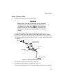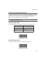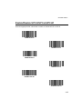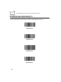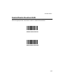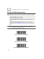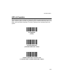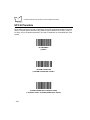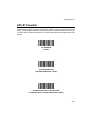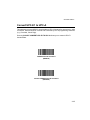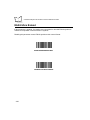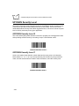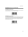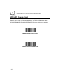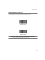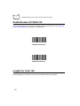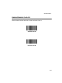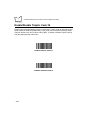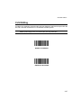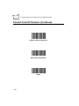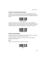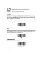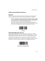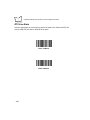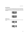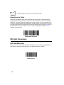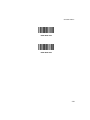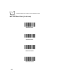
1
P370/P470 Keyless
RF Scanners
Product Reference Guide
P370/P470 Keyless RF Scanners
Product Reference Guide
72-61496-02
Revision A
April 2003
© 2003 by Symbol Technologies, Inc. All rights reserved.
No part of this publication may be reproduced or used in any form, or by any electrical or
mechanical means, without permission in writing from Symbol. This includes electronic or
mechanical means, such as photocopying, recording, or information storage and retrieval
systems. The material in this manual is subject to change without notice.
The software is provided strictly on an “as is” basis. All software, including firmware,
furnished to the user is on a licensed basis. Symbol grants to the user a non-transferable
and non-exclusive license to use each software or firmware program delivered hereunder
(licensed program). Except as noted below, such license may not be assigned,
sublicensed, or otherwise transferred by the user without prior written consent of Symbol.
No right to copy a licensed program in whole or in part is granted, except as permitted under
copyright law. The user shall not modify, merge, or incorporate any form or portion of a
licensed program with other program material, create a derivative work from a licensed
program, or use a licensed program in a network without written permission from Symbol.
The user agrees to maintain Symbol’s copyright notice on the licensed programs delivered
hereunder, and to include the same on any authorized copies it makes, in whole or in part.
The user agrees not to decompile, disassemble, decode, or reverse engineer any licensed
program delivered to the user or any portion thereof.
Symbol reserves the right to make changes to any software or product to improve reliability,
function, or design.
Symbol does not assume any product liability arising out of, or in connection with, the
application or use of any product, circuit, or application described herein.
No license is granted, either expressly or by implication, estoppel, or otherwise under any
Symbol Technologies, Inc., intellectual property rights. An implied license only exists for
equipment, circuits, and subsystems contained in Symbol products.
Symbol, Spectrum One, and Spectrum24 are registered trademarks of Symbol
Technologies, Inc. Other product names mentioned in this manual may be trademarks or
registered trademarks of their respective companies and are hereby acknowledged.
Symbol Technologies, Inc.
One Symbol Plaza
Holtsville, New York 11742-1300
http://www.symbol.com
2
Contents
About This Manual
Introduction . . . . . . . . . . . . . . . . . . . . . . . . . . . . . . . . . . . . . . . . . . . . . . . . . . . . . . . . . . . . . . . . . . . . ix
Chapter Descriptions . . . . . . . . . . . . . . . . . . . . . . . . . . . . . . . . . . . . . . . . . . . . . . . . . . . . . . . . . . . . . ix
Notational Conventions . . . . . . . . . . . . . . . . . . . . . . . . . . . . . . . . . . . . . . . . . . . . . . . . . . . . . . . . . . . ix
Related Publications . . . . . . . . . . . . . . . . . . . . . . . . . . . . . . . . . . . . . . . . . . . . . . . . . . . . . . . . . . . . . x
Service Information . . . . . . . . . . . . . . . . . . . . . . . . . . . . . . . . . . . . . . . . . . . . . . . . . . . . . . . . . . . . . . x
Symbol Support Center . . . . . . . . . . . . . . . . . . . . . . . . . . . . . . . . . . . . . . . . . . . . . . . . . . . . . . . xi
Chapter 1. Getting Started
Introduction . . . . . . . . . . . . . . . . . . . . . . . . . . . . . . . . . . . . . . . . . . . . . . . . . . . . . . . . . . . . . . . . . . 1-1
Accessories . . . . . . . . . . . . . . . . . . . . . . . . . . . . . . . . . . . . . . . . . . . . . . . . . . . . . . . . . . . . . . . . . . 1-2
Rechargeable Battery . . . . . . . . . . . . . . . . . . . . . . . . . . . . . . . . . . . . . . . . . . . . . . . . . . . . . . . 1-2
The Cradle . . . . . . . . . . . . . . . . . . . . . . . . . . . . . . . . . . . . . . . . . . . . . . . . . . . . . . . . . . . . . . . 1-2
Unpacking . . . . . . . . . . . . . . . . . . . . . . . . . . . . . . . . . . . . . . . . . . . . . . . . . . . . . . . . . . . . . . . . . . . 1-3
Setting Up the Cradle . . . . . . . . . . . . . . . . . . . . . . . . . . . . . . . . . . . . . . . . . . . . . . . . . . . . . . . . . . 1-3
Connecting to a Host . . . . . . . . . . . . . . . . . . . . . . . . . . . . . . . . . . . . . . . . . . . . . . . . . . . . . . . 1-3
Wall Mounting . . . . . . . . . . . . . . . . . . . . . . . . . . . . . . . . . . . . . . . . . . . . . . . . . . . . . . . . . . . . . 1-6
Pairing the Scanner with the Cradle . . . . . . . . . . . . . . . . . . . . . . . . . . . . . . . . . . . . . . . . . . . . 1-8
Optimizing RF Performance. . . . . . . . . . . . . . . . . . . . . . . . . . . . . . . . . . . . . . . . . . . . . . . . . . . . . . 1-9
Mounting . . . . . . . . . . . . . . . . . . . . . . . . . . . . . . . . . . . . . . . . . . . . . . . . . . . . . . . . . . . . . . . . . 1-9
Coexistence in Spectrum24 Environments. . . . . . . . . . . . . . . . . . . . . . . . . . . . . . . . . . . . . . . 1-9
Phaser-to-Phaser Co-Existence . . . . . . . . . . . . . . . . . . . . . . . . . . . . . . . . . . . . . . . . . . . . . . 1-10
Charging the Battery . . . . . . . . . . . . . . . . . . . . . . . . . . . . . . . . . . . . . . . . . . . . . . . . . . . . . . . . . . 1-10
Using the Cradle . . . . . . . . . . . . . . . . . . . . . . . . . . . . . . . . . . . . . . . . . . . . . . . . . . . . . . . . . . 1-11
Using the UBC 2000 . . . . . . . . . . . . . . . . . . . . . . . . . . . . . . . . . . . . . . . . . . . . . . . . . . . . . . . 1-11
Charge Status LED Indications . . . . . . . . . . . . . . . . . . . . . . . . . . . . . . . . . . . . . . . . . . . . . . . . . . 1-12
Changing the Battery . . . . . . . . . . . . . . . . . . . . . . . . . . . . . . . . . . . . . . . . . . . . . . . . . . . . . . . . . . 1-12
Removing the Battery . . . . . . . . . . . . . . . . . . . . . . . . . . . . . . . . . . . . . . . . . . . . . . . . . . . . . . 1-13
Inserting the Battery . . . . . . . . . . . . . . . . . . . . . . . . . . . . . . . . . . . . . . . . . . . . . . . . . . . . . . . 1-13
iii
P370/P470 Keyless RF Scanners Product Reference Guide
Chapter 2. Operation
Introduction . . . . . . . . . . . . . . . . . . . . . . . . . . . . . . . . . . . . . . . . . . . . . . . . . . . . . . . . . . . . . . . . . . . 2-1
Default Application . . . . . . . . . . . . . . . . . . . . . . . . . . . . . . . . . . . . . . . . . . . . . . . . . . . . . . . . . . . . . 2-1
Initial Powerup . . . . . . . . . . . . . . . . . . . . . . . . . . . . . . . . . . . . . . . . . . . . . . . . . . . . . . . . . . . . . 2-1
Scan and Transmit Application . . . . . . . . . . . . . . . . . . . . . . . . . . . . . . . . . . . . . . . . . . . . . . . . 2-1
Communication Errors . . . . . . . . . . . . . . . . . . . . . . . . . . . . . . . . . . . . . . . . . . . . . . . . . . . . . . . . . . 2-2
RF Communication Errors . . . . . . . . . . . . . . . . . . . . . . . . . . . . . . . . . . . . . . . . . . . . . . . . . . . . 2-2
Host / Cradle Communication Errors . . . . . . . . . . . . . . . . . . . . . . . . . . . . . . . . . . . . . . . . . . . . 2-2
System Setup . . . . . . . . . . . . . . . . . . . . . . . . . . . . . . . . . . . . . . . . . . . . . . . . . . . . . . . . . . . . . . . . . 2-3
MCL-Designer . . . . . . . . . . . . . . . . . . . . . . . . . . . . . . . . . . . . . . . . . . . . . . . . . . . . . . . . . . . . . . . . . 2-8
123Scan . . . . . . . . . . . . . . . . . . . . . . . . . . . . . . . . . . . . . . . . . . . . . . . . . . . . . . . . . . . . . . . . . . . . . 2-8
Suffix Values . . . . . . . . . . . . . . . . . . . . . . . . . . . . . . . . . . . . . . . . . . . . . . . . . . . . . . . . . . . . . 2-10
Scanning . . . . . . . . . . . . . . . . . . . . . . . . . . . . . . . . . . . . . . . . . . . . . . . . . . . . . . . . . . . . . . . . . . . . 2-14
Scan the Entire Symbol . . . . . . . . . . . . . . . . . . . . . . . . . . . . . . . . . . . . . . . . . . . . . . . . . . . . . 2-15
Hold at an Angle . . . . . . . . . . . . . . . . . . . . . . . . . . . . . . . . . . . . . . . . . . . . . . . . . . . . . . . . . . 2-15
Decode Zone . . . . . . . . . . . . . . . . . . . . . . . . . . . . . . . . . . . . . . . . . . . . . . . . . . . . . . . . . . . . . . . . 2-16
Chapter 3. Maintenance And Specifications
Introduction . . . . . . . . . . . . . . . . . . . . . . . . . . . . . . . . . . . . . . . . . . . . . . . . . . . . . . . . . . . . . . . . . . . 3-1
Maintenance . . . . . . . . . . . . . . . . . . . . . . . . . . . . . . . . . . . . . . . . . . . . . . . . . . . . . . . . . . . . . . . . . . 3-1
Troubleshooting . . . . . . . . . . . . . . . . . . . . . . . . . . . . . . . . . . . . . . . . . . . . . . . . . . . . . . . . . . . . . . . 3-2
Beeper Indications . . . . . . . . . . . . . . . . . . . . . . . . . . . . . . . . . . . . . . . . . . . . . . . . . . . . . . . . . . . . . 3-5
Technical Specifications . . . . . . . . . . . . . . . . . . . . . . . . . . . . . . . . . . . . . . . . . . . . . . . . . . . . . . . . . 3-6
Cradle Pin-outs . . . . . . . . . . . . . . . . . . . . . . . . . . . . . . . . . . . . . . . . . . . . . . . . . . . . . . . . . . . . . . . . 3-7
Chapter 4. Parameter Menus
Introduction . . . . . . . . . . . . . . . . . . . . . . . . . . . . . . . . . . . . . . . . . . . . . . . . . . . . . . . . . . . . . . . . . . . 4-1
Operational Parameters . . . . . . . . . . . . . . . . . . . . . . . . . . . . . . . . . . . . . . . . . . . . . . . . . . . . . . . . . 4-1
Set Default Parameter. . . . . . . . . . . . . . . . . . . . . . . . . . . . . . . . . . . . . . . . . . . . . . . . . . . . . . . . . . . 4-7
Communication Protocol . . . . . . . . . . . . . . . . . . . . . . . . . . . . . . . . . . . . . . . . . . . . . . . . . . . . . . . . . 4-8
Host Type . . . . . . . . . . . . . . . . . . . . . . . . . . . . . . . . . . . . . . . . . . . . . . . . . . . . . . . . . . . . . . . . . . . . 4-9
RS-232C Host Types . . . . . . . . . . . . . . . . . . . . . . . . . . . . . . . . . . . . . . . . . . . . . . . . . . . . . . . . 4-9
Host Response Timeout . . . . . . . . . . . . . . . . . . . . . . . . . . . . . . . . . . . . . . . . . . . . . . . . . . . . . . . . 4-12
RF Channel . . . . . . . . . . . . . . . . . . . . . . . . . . . . . . . . . . . . . . . . . . . . . . . . . . . . . . . . . . . . . . . . . . 4-13
RF Retries . . . . . . . . . . . . . . . . . . . . . . . . . . . . . . . . . . . . . . . . . . . . . . . . . . . . . . . . . . . . . . . . . . . 4-13
Beeper Tone . . . . . . . . . . . . . . . . . . . . . . . . . . . . . . . . . . . . . . . . . . . . . . . . . . . . . . . . . . . . . . . . . 4-15
Beeper Volume . . . . . . . . . . . . . . . . . . . . . . . . . . . . . . . . . . . . . . . . . . . . . . . . . . . . . . . . . . . . . . . 4-16
Power Detect Beep . . . . . . . . . . . . . . . . . . . . . . . . . . . . . . . . . . . . . . . . . . . . . . . . . . . . . . . . . . . . 4-17
Beep After Good Decode . . . . . . . . . . . . . . . . . . . . . . . . . . . . . . . . . . . . . . . . . . . . . . . . . . . . . . . 4-18
Laser On Time . . . . . . . . . . . . . . . . . . . . . . . . . . . . . . . . . . . . . . . . . . . . . . . . . . . . . . . . . . . . . . . 4-19
Transmit “No Read” Message . . . . . . . . . . . . . . . . . . . . . . . . . . . . . . . . . . . . . . . . . . . . . . . . . . . . 4-20
iv
Contents
Linear Code Type Security Level. . . . . . . . . . . . . . . . . . . . . . . . . . . . . . . . . . . . . . . . . . . . . . . . .
Linear Security Level 1 . . . . . . . . . . . . . . . . . . . . . . . . . . . . . . . . . . . . . . . . . . . . . . . . . . . . .
Linear Security Level 2 . . . . . . . . . . . . . . . . . . . . . . . . . . . . . . . . . . . . . . . . . . . . . . . . . . . . .
Linear Security Level 3 . . . . . . . . . . . . . . . . . . . . . . . . . . . . . . . . . . . . . . . . . . . . . . . . . . . . .
Linear Security Level 4 . . . . . . . . . . . . . . . . . . . . . . . . . . . . . . . . . . . . . . . . . . . . . . . . . . . . .
Bi-directional Redundancy . . . . . . . . . . . . . . . . . . . . . . . . . . . . . . . . . . . . . . . . . . . . . . . . . . . . . .
Autodiscriminate Response Time . . . . . . . . . . . . . . . . . . . . . . . . . . . . . . . . . . . . . . . . . . . . . . . .
Enable/Disable UPC-E/UPC-A/UPC-E1 . . . . . . . . . . . . . . . . . . . . . . . . . . . . . . . . . . . . . . . . . . .
Enable/Disable EAN-8/EAN-13 . . . . . . . . . . . . . . . . . . . . . . . . . . . . . . . . . . . . . . . . . . . . . . . . . .
Enable/Disable Bookland EAN . . . . . . . . . . . . . . . . . . . . . . . . . . . . . . . . . . . . . . . . . . . . . . . . . .
Decode UPC/EAN Supplementals. . . . . . . . . . . . . . . . . . . . . . . . . . . . . . . . . . . . . . . . . . . . . . . .
Decode UPC/EAN Supplemental Redundancy . . . . . . . . . . . . . . . . . . . . . . . . . . . . . . . . . . . . . .
Transmit UPC-A/UPC-E/UPC-E1 Check Digit . . . . . . . . . . . . . . . . . . . . . . . . . . . . . . . . . . . . . . .
UPC-A Preamble . . . . . . . . . . . . . . . . . . . . . . . . . . . . . . . . . . . . . . . . . . . . . . . . . . . . . . . . . . . . .
UPC-E Preamble . . . . . . . . . . . . . . . . . . . . . . . . . . . . . . . . . . . . . . . . . . . . . . . . . . . . . . . . . . . . .
UPC-E1 Preamble . . . . . . . . . . . . . . . . . . . . . . . . . . . . . . . . . . . . . . . . . . . . . . . . . . . . . . . . . . . .
Convert UPC-E to UPC-A . . . . . . . . . . . . . . . . . . . . . . . . . . . . . . . . . . . . . . . . . . . . . . . . . . . . . .
Convert UPC-E1 to UPC-A . . . . . . . . . . . . . . . . . . . . . . . . . . . . . . . . . . . . . . . . . . . . . . . . . . . . .
EAN-8 Zero Extend . . . . . . . . . . . . . . . . . . . . . . . . . . . . . . . . . . . . . . . . . . . . . . . . . . . . . . . . . . .
Convert EAN-8 to EAN-13 Type . . . . . . . . . . . . . . . . . . . . . . . . . . . . . . . . . . . . . . . . . . . . . . . . .
UPC/EAN Security Level . . . . . . . . . . . . . . . . . . . . . . . . . . . . . . . . . . . . . . . . . . . . . . . . . . . . . . .
UPC/EAN Security Level 0 . . . . . . . . . . . . . . . . . . . . . . . . . . . . . . . . . . . . . . . . . . . . . . . . . .
UPC/EAN Security Level 1 . . . . . . . . . . . . . . . . . . . . . . . . . . . . . . . . . . . . . . . . . . . . . . . . . .
UPC/EAN Security Level 2 . . . . . . . . . . . . . . . . . . . . . . . . . . . . . . . . . . . . . . . . . . . . . . . . . .
UPC/EAN Security Level 3 . . . . . . . . . . . . . . . . . . . . . . . . . . . . . . . . . . . . . . . . . . . . . . . . . .
UPC/EAN Coupon Code . . . . . . . . . . . . . . . . . . . . . . . . . . . . . . . . . . . . . . . . . . . . . . . . . . . . . . .
Enable/Disable Code 128 . . . . . . . . . . . . . . . . . . . . . . . . . . . . . . . . . . . . . . . . . . . . . . . . . . . . . .
Enable/Disable UCC/EAN-128 . . . . . . . . . . . . . . . . . . . . . . . . . . . . . . . . . . . . . . . . . . . . . . . . . .
Lengths for Code 128 . . . . . . . . . . . . . . . . . . . . . . . . . . . . . . . . . . . . . . . . . . . . . . . . . . . . . . . . .
Enable/Disable Code 39 . . . . . . . . . . . . . . . . . . . . . . . . . . . . . . . . . . . . . . . . . . . . . . . . . . . . . . .
Enable/Disable Trioptic Code 39 . . . . . . . . . . . . . . . . . . . . . . . . . . . . . . . . . . . . . . . . . . . . . . . . .
Set Lengths for Code 39 . . . . . . . . . . . . . . . . . . . . . . . . . . . . . . . . . . . . . . . . . . . . . . . . . . . . . . .
Code 39 Check Digit Verification . . . . . . . . . . . . . . . . . . . . . . . . . . . . . . . . . . . . . . . . . . . . . . . . .
Transmit Code 39 Check Digit . . . . . . . . . . . . . . . . . . . . . . . . . . . . . . . . . . . . . . . . . . . . . . . . . . .
Enable/Disable Code 39 Full ASCII . . . . . . . . . . . . . . . . . . . . . . . . . . . . . . . . . . . . . . . . . . . . . . .
Convert Code 39 to Code 32 . . . . . . . . . . . . . . . . . . . . . . . . . . . . . . . . . . . . . . . . . . . . . . . . . . . .
Code 32 Prefix . . . . . . . . . . . . . . . . . . . . . . . . . . . . . . . . . . . . . . . . . . . . . . . . . . . . . . . . . . . . . . .
Enable/Disable Code 93 . . . . . . . . . . . . . . . . . . . . . . . . . . . . . . . . . . . . . . . . . . . . . . . . . . . . . . .
Set Lengths for Code 93 . . . . . . . . . . . . . . . . . . . . . . . . . . . . . . . . . . . . . . . . . . . . . . . . . . . . . . .
Enable/Disable Interleaved 2 of 5 . . . . . . . . . . . . . . . . . . . . . . . . . . . . . . . . . . . . . . . . . . . . . . . .
Set Lengths for Interleaved 2 of 5 . . . . . . . . . . . . . . . . . . . . . . . . . . . . . . . . . . . . . . . . . . . . . . . .
I 2 of 5 Check Digit Verification . . . . . . . . . . . . . . . . . . . . . . . . . . . . . . . . . . . . . . . . . . . . . . . . . .
Transmit I 2 of 5 Check Digit . . . . . . . . . . . . . . . . . . . . . . . . . . . . . . . . . . . . . . . . . . . . . . . . . . . .
Convert I 2 of 5 to EAN-13. . . . . . . . . . . . . . . . . . . . . . . . . . . . . . . . . . . . . . . . . . . . . . . . . . . . . .
4-21
4-21
4-21
4-22
4-22
4-23
4-24
4-25
4-26
4-27
4-28
4-29
4-30
4-31
4-32
4-33
4-34
4-35
4-36
4-37
4-38
4-38
4-38
4-39
4-39
4-40
4-41
4-42
4-42
4-43
4-44
4-45
4-47
4-48
4-49
4-50
4-51
4-52
4-53
4-55
4-56
4-58
4-59
4-60
v
P370/P470 Keyless RF Scanners Product Reference Guide
Enable/Disable Discrete 2 of 5 . . . . . . . . . . . . . . . . . . . . . . . . . . . . . . . . . . . . . . . . . . . . . . . . . . . 4-61
Set Lengths for Discrete 2 of 5 . . . . . . . . . . . . . . . . . . . . . . . . . . . . . . . . . . . . . . . . . . . . . . . . . . . 4-62
Enable/Disable Codabar . . . . . . . . . . . . . . . . . . . . . . . . . . . . . . . . . . . . . . . . . . . . . . . . . . . . . . . . 4-64
Set Lengths for Codabar . . . . . . . . . . . . . . . . . . . . . . . . . . . . . . . . . . . . . . . . . . . . . . . . . . . . . . . . 4-65
CLSI Editing . . . . . . . . . . . . . . . . . . . . . . . . . . . . . . . . . . . . . . . . . . . . . . . . . . . . . . . . . . . . . . . . . 4-67
NOTIS Editing . . . . . . . . . . . . . . . . . . . . . . . . . . . . . . . . . . . . . . . . . . . . . . . . . . . . . . . . . . . . . . . . 4-68
Enable/Disable MSI Plessey . . . . . . . . . . . . . . . . . . . . . . . . . . . . . . . . . . . . . . . . . . . . . . . . . . . . . 4-69
Set Lengths for MSI Plessey. . . . . . . . . . . . . . . . . . . . . . . . . . . . . . . . . . . . . . . . . . . . . . . . . . . . . 4-70
MSI Plessey Check Digits . . . . . . . . . . . . . . . . . . . . . . . . . . . . . . . . . . . . . . . . . . . . . . . . . . . . . . . 4-72
Transmit MSI Plessey Check Digit . . . . . . . . . . . . . . . . . . . . . . . . . . . . . . . . . . . . . . . . . . . . . . . . 4-73
MSI Plessey Check Digit Algorithm. . . . . . . . . . . . . . . . . . . . . . . . . . . . . . . . . . . . . . . . . . . . . . . . 4-74
Transmit Code ID Character . . . . . . . . . . . . . . . . . . . . . . . . . . . . . . . . . . . . . . . . . . . . . . . . . . . . . 4-75
Symbol Code ID Characters . . . . . . . . . . . . . . . . . . . . . . . . . . . . . . . . . . . . . . . . . . . . . . . . . 4-75
Pause Duration . . . . . . . . . . . . . . . . . . . . . . . . . . . . . . . . . . . . . . . . . . . . . . . . . . . . . . . . . . . . . . . 4-77
RS-232C Parameters . . . . . . . . . . . . . . . . . . . . . . . . . . . . . . . . . . . . . . . . . . . . . . . . . . . . . . . . . . 4-78
Baud Rate . . . . . . . . . . . . . . . . . . . . . . . . . . . . . . . . . . . . . . . . . . . . . . . . . . . . . . . . . . . . . . . 4-78
Baud Rate (Continued) . . . . . . . . . . . . . . . . . . . . . . . . . . . . . . . . . . . . . . . . . . . . . . . . . . . . . 4-79
Parity . . . . . . . . . . . . . . . . . . . . . . . . . . . . . . . . . . . . . . . . . . . . . . . . . . . . . . . . . . . . . . . . . . . 4-80
Parity (Continued) . . . . . . . . . . . . . . . . . . . . . . . . . . . . . . . . . . . . . . . . . . . . . . . . . . . . . . . . . 4-81
Check Receive Errors . . . . . . . . . . . . . . . . . . . . . . . . . . . . . . . . . . . . . . . . . . . . . . . . . . . . . . 4-82
Hardware Handshaking . . . . . . . . . . . . . . . . . . . . . . . . . . . . . . . . . . . . . . . . . . . . . . . . . . . . . 4-83
Hardware Handshaking (Continued) . . . . . . . . . . . . . . . . . . . . . . . . . . . . . . . . . . . . . . . . . . . 4-84
Hardware Handshaking (Continued) . . . . . . . . . . . . . . . . . . . . . . . . . . . . . . . . . . . . . . . . . . . 4-85
Software Handshaking. . . . . . . . . . . . . . . . . . . . . . . . . . . . . . . . . . . . . . . . . . . . . . . . . . . . . . 4-85
Software Handshaking (Continued) . . . . . . . . . . . . . . . . . . . . . . . . . . . . . . . . . . . . . . . . . . . . 4-86
Software Handshaking (Continued) . . . . . . . . . . . . . . . . . . . . . . . . . . . . . . . . . . . . . . . . . . . . 4-87
Host Serial Response Time-out . . . . . . . . . . . . . . . . . . . . . . . . . . . . . . . . . . . . . . . . . . . . . . . 4-87
RTS Line State . . . . . . . . . . . . . . . . . . . . . . . . . . . . . . . . . . . . . . . . . . . . . . . . . . . . . . . . . . . 4-88
Stop Bit Select . . . . . . . . . . . . . . . . . . . . . . . . . . . . . . . . . . . . . . . . . . . . . . . . . . . . . . . . . . . . 4-89
ASCII Format . . . . . . . . . . . . . . . . . . . . . . . . . . . . . . . . . . . . . . . . . . . . . . . . . . . . . . . . . . . . . 4-89
Intercharacter Delay. . . . . . . . . . . . . . . . . . . . . . . . . . . . . . . . . . . . . . . . . . . . . . . . . . . . . . . . 4-90
MCL-Net Parameters . . . . . . . . . . . . . . . . . . . . . . . . . . . . . . . . . . . . . . . . . . . . . . . . . . . . . . . . . . 4-90
MCL-Net Baud Rate. . . . . . . . . . . . . . . . . . . . . . . . . . . . . . . . . . . . . . . . . . . . . . . . . . . . . . . . 4-90
MCL-Net Baud Rate (Continued). . . . . . . . . . . . . . . . . . . . . . . . . . . . . . . . . . . . . . . . . . . . . . 4-92
MCL-Net Hex Addressing Mode . . . . . . . . . . . . . . . . . . . . . . . . . . . . . . . . . . . . . . . . . . . . . . 4-93
Scanner ID . . . . . . . . . . . . . . . . . . . . . . . . . . . . . . . . . . . . . . . . . . . . . . . . . . . . . . . . . . . . . . . 4-94
MCL-Net Transmit Retries . . . . . . . . . . . . . . . . . . . . . . . . . . . . . . . . . . . . . . . . . . . . . . . . . . . 4-94
MCL-Net Frame Timeout . . . . . . . . . . . . . . . . . . . . . . . . . . . . . . . . . . . . . . . . . . . . . . . . . . . . 4-94
Scanner Decode Beep Type . . . . . . . . . . . . . . . . . . . . . . . . . . . . . . . . . . . . . . . . . . . . . . . . . 4-95
Long Range Scanning Bar Codes. . . . . . . . . . . . . . . . . . . . . . . . . . . . . . . . . . . . . . . . . . . . . . . . . 4-96
Aim Mode. . . . . . . . . . . . . . . . . . . . . . . . . . . . . . . . . . . . . . . . . . . . . . . . . . . . . . . . . . . . . . . . 4-96
Aim Duration . . . . . . . . . . . . . . . . . . . . . . . . . . . . . . . . . . . . . . . . . . . . . . . . . . . . . . . . . . . . . 4-97
Numeric Bar Codes. . . . . . . . . . . . . . . . . . . . . . . . . . . . . . . . . . . . . . . . . . . . . . . . . . . . . . . . . . . . 4-98
Cancel . . . . . . . . . . . . . . . . . . . . . . . . . . . . . . . . . . . . . . . . . . . . . . . . . . . . . . . . . . . . . . . . . 4-100
vi
Contents
Appendix A. Bar Code Information
UCC/EAN-128 . . . . . . . . . . . . . . . . . . . . . . . . . . . . . . . . . . . . . . . . . . . . . . . . . . . . . . . . . . . . . . . . A-1
AIM Code Identifiers . . . . . . . . . . . . . . . . . . . . . . . . . . . . . . . . . . . . . . . . . . . . . . . . . . . . . . . . . . . A-3
Appendix B. Radio Channels
Cordless Phaser RF Channels Per Country . . . . . . . . . . . . . . . . . . . . . . . . . . . . . . . . . . . . . . . . . B-1
Appendix C. Error Indications and Beeps
Introduction . . . . . . . . . . . . . . . . . . . . . . . . . . . . . . . . . . . . . . . . . . . . . . . . . . . . . . . . . . . . . . . . . .
Indications . . . . . . . . . . . . . . . . . . . . . . . . . . . . . . . . . . . . . . . . . . . . . . . . . . . . . . . . . . . . . . . . . . .
Communication Errors . . . . . . . . . . . . . . . . . . . . . . . . . . . . . . . . . . . . . . . . . . . . . . . . . . . . . . . . . .
Scanning Transmission Range. . . . . . . . . . . . . . . . . . . . . . . . . . . . . . . . . . . . . . . . . . . . . . . .
MCL-Code Errors. . . . . . . . . . . . . . . . . . . . . . . . . . . . . . . . . . . . . . . . . . . . . . . . . . . . . . . . . . . . . .
C-1
C-1
C-2
C-2
C-4
Index
Feedback
vii
P370/P470 Keyless RF Scanners Product Reference Guide
viii
About This Manual
Introduction
The P370/P470 Keyless RF Scanners Product Reference Guide provides general
instructions for setting up, operating, troubleshooting, maintaining and programming the
P370 (industrial) and P470 (retail) cordless RF scanners.
Chapter Descriptions
•
Chapter 1, Getting Started, describes the scanner and quick startup instructions.
•
Chapter 2, Operation, explains how to operate the scanner.
•
Chapter 3, Maintenance And Specifications, talks about the maintenance and the
specifications of the scanner and the cradle.
•
Chapter 4, Parameter Menus, has all the optional parameter bar codes for
personalizing your scanner.
•
Appendix A, Bar Code Information, has information about bar codes.
•
Appendix B, Radio Channels, lists the available RF channels per Country.
•
Appendix C, Error Indications and Beeps, describes possible error codes displayed
on the scanner.
Notational Conventions
The following conventions are used in this document:
•
Italics are used to highlight specific items in the general text, and to identify
chapters and sections in this and related documents.
•
Bullets (•) indicate:
ix
P370/P470 Keyless RF Scanners Product Reference Guide
•
•
action items
•
lists of alternatives
•
lists of required steps that are not necessarily sequential
Sequential lists (e.g., those that describe step-by-step procedures) appear as
numbered lists.
Related Publications
•
P370/P470 Keyless RF Scanners Quick Reference Guide, p/n 72-61497-xx
•
PL 370/470 Cradle Quick Reference Guide, p/n 72-38494-xx
•
MCL Designer for Phaser Series User’s Guide, p/n 70-37689-xx
•
MCL-Designer Programming Requirements, p/n 72-61838-xx.
Service Information
If you have a problem with your equipment, contact the Symbol Support Center for your
region. See page xi for contact information. Before calling, have the model number, serial
number, and several of your bar code symbols at hand.
Call the Support Center from a phone near the scanning equipment so that the service
person can try to talk you through your problem. If the equipment is found to be working
properly and the problem is symbol readability, the Support Center will request samples of
your bar codes for analysis at our plant.
If your problem cannot be solved over the phone, you may need to return your equipment
for servicing. If that is necessary, you will be given specific directions.
Note: Symbol Technologies is not responsible for any damages incurred
during shipment if the approved shipping container is not used.
Shipping the units improperly can possibly void the warranty. If the
original shipping container was not kept, contact Symbol to have
another sent to you.
x
About This Guide
Symbol Support Center
For service information, warranty information or technical assistance contact or call the
Symbol Support Center in:
United States 1
Symbol Technologies, Inc.
One Symbol Plaza
Holtsville, New York 11742-1300
1-800-653-5350
Canada
Symbol Technologies Canada, Inc.
2540 Matheson Boulevard East
Mississauga, Ontario, Canada L4W 4Z2
905-629-7226
United Kingdom
Symbol Technologies
Symbol Place
Winnersh Triangle, Berkshire RG41 5TP
United Kingdom
0800 328 2424 (Inside UK)
+44 118 945 7529 (Outside UK)
Asia/Pacific
Symbol Technologies Asia, Inc (Singapore
Branch)
230 Victoria Street #05-07/09
Bugis Junction Office Tower
Singapore 188024
Tel : +65-6796-9600
Fax : +65-6337-6488
Australia
Symbol Technologies Pty. Ltd.
432 St. Kilda Road
Melbourne, Victoria 3004
1-800-672-906 (Inside Australia)
+61-3-9866-6044 (Outside Australia)
Austria/Österreich
Symbol Technologies Austria GmbH
Prinz-Eugen Strasse 70 / 2.Haus
1040 Vienna, Austria
01-5055794-0 (Inside Austria)
+43-1-5055794-0 (Outside Austria)
Denmark/Danmark
Symbol Technologies AS
Dr. Neergaardsvej 3
2970 Hørsholm
7020-1718 (Inside Denmark)
+45-7020-1718 (Outside Denmark)
Europe/Mid-East Distributor Operations
Contact your local distributor or call
+44 118 945 7360
xi
P370/P470 Keyless RF Scanners Product Reference Guide
Finland/Suomi
Oy Symbol Technologies
Kaupintie 8 A 6
FIN-00440 Helsinki, Finland
9 5407 580 (Inside Finland)
+358 9 5407 580 (Outside Finland)
France
Symbol Technologies France
Centre d’Affaire d’Antony
3 Rue de la Renaissance
92184 Antony Cedex, France
01-40-96-52-21 (Inside France)
+33-1-40-96-52-50 (Outside France)
Germany/Deutchland
Symbol Technologies GmbH
Waldstrasse 66
D-63128 Dietzenbach, Germany
6074-49020 (Inside Germany)
+49-6074-49020 (Outside Germany)
Italy/Italia
Symbol Technologies Italia S.R.L.
Via Cristoforo Columbo, 49
20090 Trezzano S/N Navigilo
Milano, Italy
2-484441 (Inside Italy)
+39-02-484441 (Outside Italy)
Latin America Sales Support
2730 University Dr.
Coral Springs, FL 33065 USA
1-800-347-0178 (Inside United States)
+1-954-255-2610 (Outside United States)
954-340-9454 (Fax)
Mexico/México
Symbol Technologies Mexico Ltd.
Torre Picasso
Boulevard Manuel Avila Camacho No 88
Lomas de Chapultepec CP 11000
Mexico City, DF, Mexico
5-520-1835 (Inside Mexico)
+52-5-520-1835 (Outside Mexico)
Netherlands/Nederland
Symbol Technologies
Kerkplein 2, 7051 CX
Postbus 24 7050 AA
Varsseveld, Netherlands
315-271700 (Inside Netherlands)
+31-315-271700 (Outside Netherlands)
Norway/Norge
Symbol’s registered and mailing address:
Symbol Technologies Norway
Hoybratenveien 35 C
N-1055 OSLO, Norway
Symbol’s repair depot and shipping address:
Symbol Technologies Norway
Enebakkveien 123
N-0680 OSLO, Norway
+47 2232 4375
xii
About This Guide
South Africa
Symbol Technologies Africa Inc.
Block B2
Rutherford Estate
1 Scott Street
Waverly 2090 Johannesburg
Republic of South Africa
11-809 5311 (Inside South Africa)
+27-11-809 5311 (Outside South Africa)
Spain/España
Symbol Technologies S.L.
Avenida de Bruselas, 22
Edificio Sauce
Alcobendas, Madrid 28108
Spain
91 324 40 00 (Inside Spain)
+34 91 324 40 00 (Outside Spain)
Fax: +34.91.324.4010
Sweden/Sverige
“Letter” address:
Symbol Technologies AB
Box 1354
S-171 26 SOLNA
Sweden
Visit/shipping address:
Symbol Technologies AB
Solna Strandväg 78
S-171 54 SOLNA
Sweden
Switchboard: 08 445 29 00 (domestic)
Call Center: +46 8 445 29 29 (international)
Support E-Mail:
[email protected]
1
Customer support is available 24 hours a day, 7 days a week.
If you purchased your Symbol product from a Symbol Business Partner, contact that
Business Partner for service.
For the latest version of this guide go to:http://www.symbol.com/manuals.
xiii
P370/P470 Keyless RF Scanners Product Reference Guide
xiv
Chapter 1
Getting Started
Introduction
The P370/P470 cordless RF scanners bring new flexibility and economy to data capture
and data management in both industrial and retail operations. The scanner communicates
with your host computer through radio transmission instead of through a cable. With the RF
scanner, you are free to scan and transmit without a physical cable, from as far away as
100 feet (30.5 meters) even without a direct line of sight. This lets you take the scanner to
where the work is, whether on the loading dock, the plant floor, the warehouse, or the POS
checkout area. There are several versions available:
•
P470: cordless retail scanner
•
P370: cordless industrial scanner
•
P370 ALR: cordless industrial long range scanner
Unless otherwise noted, the term Phaser refers to all versions of the scanner.
1-1
P370/P470 Keyless RF Scanners Product Reference Guide
Accessories
Rechargeable Battery
In the handle of the scanner, there is a rechargeable lithium-ion battery. This provides all
power to the scanner during cordless operation. It provides 10 hours of use in a typical
application. When fully depleted, the battery can be recharged to full charge in about 3-1/2
hours.
The Cradle
The PL 370/470 Cradle acts as a:
•
stand
•
2-way RF transmitter
•
communication interface with the host
•
battery charger for the cordless scanner.
The cradle can sit on a desktop or be wall-mounted, whichever is more convenient. The
cradle receives data from the scanner via the antenna on the side of the cradle. The cradle
then transmits that data to the host device via an attached cable. It also acts as a holder for
the scanner.
The cradle also provides power for charging the
scanner’s battery (in the scanner). The cradle
has a charge status indicator light that shows
the status of the battery charging (See Charge
Status LED Indications on page 1-12).
Charge Status
Indicator Light
Scanner and Cradle
There are two versions of the cradle:
•
PL 470 Cradle: cordless retail version
•
PL 370 Cradle: cordless industrial version.
Unless otherwise noted, the term Cradle refers to both versions of the cradle.
1-2
Getting Started
Unpacking
Remove the scanner from its packing and inspect it for damage. If the scanner was
damaged in transit, call one of the telephone numbers listed in the section Symbol Support
Center on page xi. KEEP THE PACKING. It is the approved shipping container and should
be used if you ever need to return your equipment for servicing.
Setting Up the Cradle
The basic steps to set up the cradle are listed below and described in more detail in the
following sections.
•
connecting the cradle to a host
•
mounting the cradle, if desired
•
pairing the scanner to the cradle.
Connecting to a Host
With some host types, the scanner is unable to answer host terminal polls if the appropriate
host type is not selected. This may result in an error message generated by the host. To
correct this situation, select the proper parameter set and initialize the host terminal. See
Chapter 4, Parameter Menus for more information.
There are two basic host communications options available:
•
using an RS-232 cable
•
using a Synapse cable.
RS-232 Connection
1. Make sure all host devices are powered down.
2. Plug the connector at the end of the cradle’s cable into the appropriate RS-232
receiving port on the host device.
1-3
P370/P470 Keyless RF Scanners Product Reference Guide
3. Plug the other end of the cable into the COM1 connector on the cradle.
COM1
Power port
Figure 1-1. Ports on the Cradle
4. Connect the power connector of the power supply into the Power port on the
cradle.
5. Connect the appropriate line cord to the power supply and into an AC receptacle.
6. The indicator light on the cradle blinks, signifying successful power-up.
Figure 1-2. Power Supply Port
7. Rotate the antenna to the vertical position.
1-4
Getting Started
Using A Synapse Cable
1. Make sure all host devices are powered down.
WARNING
Before power is provided to the cradle (step 6), the following steps must be completed. The Synapse cable must be
connected to the cradle (step 2) AND the flying power lead
plugged in (step 4). If the cables are not connected in this
sequence, the Synapse Interface Adapter will not operate
properly.
2. Connect the Synapse cable to the cradle’s COM 1 port (see Figure 1-1).
3. Connect the other end of the Synapse cable to the Synapse Interface adapter.
4. The Synapse cable has a flying power lead. Connect this lead to the receptacle in
the Synapse Interface adapter, as shown in Figure 1-3. Refer to the Synapse guide
for details.
To Host
Synapse Interface
Adapter (Module)
Synapse
Cable
Flying Power
Lead
To Cradle
Figure 1-3. Synapse and Adapter Cable
5. Connect the Synapse Interface adapter to the host.
6. Connect the power supply to the cradle (see Figure 1-2).
7. Connect the appropriate line cord to the power supply and into an AC receptacle.
1-5
P370/P470 Keyless RF Scanners Product Reference Guide
8. The indicator light on the cradle blinks, signifying successful power-up.
9. Scan the appropriate Synapse bar codes to set up the Synapse cable for your
specifications.
10. Rotate the antenna to the vertical position.
Wand Emulation, OCIA, OCR, Keyboard Wedges
See the appropriate Synapse cable instructions. An adapter cable is required.
Wall Mounting
Before wall-mounting the cradle, the scanner support tab must be changed from the deskmount position to the wall-mount position.
1. Lift the scanner support tab out of the top part of the cradle and replace it in the
wall-mount position.
Desk Mount
Wall Mount
Figure 1-4. Scanner Support Tab
1-6
Getting Started
2. Seat the cables from the bottom of the cradle in the grooves along the length of it
so that the bottom of the cradle is smooth.
Cable
Grooves
Figure 1-5. Placement of Cables
3. Fasten the two screws provided into the wall where the cradle will hang, leaving
about 1/8” (0.3 cm) of the screw outside the wall for the cradle’s wall mounting
sockets (A template is provided for you in the PL 370/470 Quick Reference Guide
p/n 72-38494-xx).
4. Place the cradle over the screw heads and slide down until it fits into place. Slight
pressure upwards should not move the cradle.
Figure 1-6. Securing Cradle to Wall
5. Position the antenna vertically (pointing toward the ceiling).
6. Place the scanner in the cradle.
1-7
P370/P470 Keyless RF Scanners Product Reference Guide
Pairing the Scanner with the Cradle
The scanner and cradle must be paired for communication to occur.
Note: If the cradle is attached to a new host, re-scan the pairing bar code.
To pair the scanner with the cradle:
1. Scan the pairing bar code on the top of the cradle.
To pair a long range scanner (P370 ALR) to a regular P370 cradle, attach the
“spare pairing bar code” label to the cradle. This 15 mil bar code, packaged with
the cradle, can be scanned by the P370 ALR at a distance of approximately two
feet from the cradle.
2. Once the base is detected, information is exchanged (addressing, RF channels,
etc.) between the scanner and the cradle.
Note: It may take up to 30 seconds for the scanner to search for the base
during over-the-air pairing. To reduce the pairing time, place the
scanner in the cradle.
3. After the exchange is complete, the scanner and cradle are paired.
Successful pairing is indicated by a warble beep and the base’s LED will flash.
If pairing is unsuccessful, the scanner emits four beeps - Lo Hi Lo Hi.
The pairing of a scanner to a cradle is one-to-one. Only one scanner can be paired
to a cradle at any point in time. If you pair a second scanner to an in use cradle, the
cradle’s connection to the first scanner will be broken and the connection reestablished with the second scanner.
To pair a scanner to a different cradle, scan its pairing bar code located on the top of the
cradle.
Caution
If you cycle power to the base or reset (remove and reinstall the battery)
the scanner, you must pair the scanner with the cradle again.
1-8
Getting Started
Optimizing RF Performance
Mounting
The RF scanner and cradle are equipped with a 2.4 GHz point-to-point radio that has an
RF transmission range of 100 feet (30.5 meters) even without a direct line of sight.
In addition to being a 2-way RF transmitter, the cradle is a battery charger and should be
mounted in an accessible location like on a table or desktop. For optimum RF performance,
especially in difficult environments, mount the cradle on a wall as high as possible.
Coexistence in Spectrum24 Environments
If you operate your scanner or cradle in close proximity to a Spectrum24 device, maintain
a buffer of 3 feet or greater between the transmitters. A Spectrum24 device includes but is
not limited to a terminal with a Spectrum24 radio, PC with a Spectrum24 card, or a
Spectrum24 Access Point. If a scanner or cradle is less than 3 ft. from a 2.4 GHz
Spectrum24 transmitter (antenna), especially an Access Point, your communication
performance may degrade.
Select a Channel Outside the Spectrum24 band
In the unlikely event that Spectrum24 radio traffic causes interference between the scanner
and the cradle, you can change the scanner’s RF channel to one that minimizes or
eliminates the interference.
Phaser cordless scanners have three channels that are not within the Spectrum24 band,
81, 82, and 83*. As a rule of thumb, the Cordless systems operated closest to Spectrum24
devices should use these channels. For instructions on how to change the scanner’s RF
channel, see System Setup Options on page 2-3.
In applications with low scanning/data transmission duty cycles, you may assign the same
channel to more than one cordless scanner.
After channels 81, 82 and 83, the next best channels to use are 60 through 80; the higher
the channel the better. See Appendix B, Radio Channels for a list of available radio
channels per country.
* Not available in some countries.
1-9
P370/P470 Keyless RF Scanners Product Reference Guide
Phaser-to-Phaser Co-Existence
Up to three P470/370 scanners within listening range (100 feet) of each other can be
operated on the same channel with little or no interference, assuming average scanning
rates.
For higher than average scanning rates, P470/370 scanners within listening range (100
feet) of each other should be operated on different channels, set apart by at least one
channel (for example, 2, 4, 6, etc.). Cordless Phaser scanners support up to 82
communication channels. Not all channels are available in all countries. Refer to Appendix
B, Radio Channels for more information.
Increase the number of RF Retries
If the scanner’s transmission is not received by the cradle or the base’s acknowledgment
response is not received by the scanner (see Communication Errors on page 2-2), the
scanner retransmits the lost or corrupted data. The scanner attempts 4 RF Retries (default)
but can be programmed to attempt up to 8.
Depending on your particular RF environment, additional retries may cause your scanner
transaction time to increase in the presence of heavy Spectrum24 traffic.
Charging the Battery
Before its first use, the scanner’s battery must be charged. It can be charged:
•
using the cradle
•
using the UBC 2000.
Note: When the battery’s charge is almost depleted, the scanner emits 4
Hi tone beeps, when the trigger is pulled, indicating that it must be
recharged.
1-10
Getting Started
Using the Cradle
1. Set up the cradle as described in Setting Up the Cradle on page 1-3.
Figure 1-7. Placing the Scanner into the Cradle
2. Insert the scanner into the cradle so that the nose of the scanner and tip of the
handle seat into the receptacles. The battery charges automatically. A full charge
of a depleted battery takes approximately 3-1/2 hours.
For charging indications, see Charge Status LED Indications on page 1-12.
The cradle recharges batteries in the scanner only when the scanner is in the cradle. A
scanner with a depleted battery starts charging immediately upon insertion into the cradle,
whereas a scanner with a partially charged battery begins charging after approximately 15
minutes. Note that the scanner can be removed from the cradle at any time.
Using the UBC 2000
The battery can be charged using the Universal Battery Charger UBC 2000. The UBC
adapter for the P370/P470 scanner battery is required. Refer to the UBC 2000 Universal
Battery Charger Product Guide for information on recharging the battery using the UBC
2000.
1-11
P370/P470 Keyless RF Scanners Product Reference Guide
Charge Status LED Indications
The LED indicator on the cradle uses flashing patterns to display the charger status, as
shown in the table below.
Table 1-1. Cradle LED Indications
LED
Status
Off
The scanner is not in the cradle or has not been
properly inserted into the cradle.
Blinking Slowly
The scanner is properly seated in the cradle and
charging will begin shortly.
Blinking Rapidly
The battery is actively charging.
On
If scanner is in cradle - battery charging is
complete.
If scanner is not in cradle - base is locked up. Cycle
power (power off then on) to the base.
Changing the Battery
Once a battery is fully charged, it will generally last up to 10 hours without being returned
to the cradle. By returning it to the cradle during the day, you extend this time.
If a significant decrease in battery life is noticed and does not correspond to increased
usage, consider replacing the battery.
1-12
Getting Started
Removing the Battery
1. Slide the release latch down using center indent and remove the cover.
It may be useful to use a coin for extra leverage:
Battery
Compartment
Cover
Battery
Release
Latch
Figure 1-8. Removing the Battery Compartment Cover
2. Slide the battery toward the bottom of the scanner and then, using the pull tab, pull
the bottom of the battery back and out of the scanner.
Pull Tab
Figure 1-9. Pulling the Battery Out
Inserting the Battery
1. Place the top portion of the battery (curved side up, contacts toward top) into the
scanner and then slide it up the handle.
2. Replace the battery compartment cover.
3. Slide the release latch up to secure the cover in place.
1-13
P370/P470 Keyless RF Scanners Product Reference Guide
1-14
Chapter 2
Operation
Introduction
This chapter covers how to use the cordless Phaser scanner.
Default Application
The cordless scanner is shipped from the factory with a default scan and transmit
application.
Initial Powerup
After initialization, the scanner enters the Scan & Transmit application. The default
communication protocol is RS232/Synapse.
If a Synapse cable is attached, the scanner automatically overrides the default settings.
Scan and Transmit Application
The scan and transmit application allows you to transmit data to a host. Scanned bar codes
are automatically transmitted to the cradle and then the host in real time.
2-1
P370/P470 Keyless RF Scanners Product Reference Guide
Communication Errors
A communication error occurs when the scanner, cradle or host fails to properly
communicate. When a communication error occurs using the default application, the
scanner emits 4 beeps (long Lo). For a detailed list of all the error codes see Appendix C,
Error Indications and Beeps and Beeper Indications on page 3-5.
Three types of communication errors can occur:
1. The RF transmitted data was NOT received by the cradle.
2. The cradle received the RF transmitted data, but the scanner did NOT receive a
cradle’s acknowledgment.
3. The host and cradle are not communicating properly.
RF Communication Errors
1. If the RF transmitted data was NOT received by the cradle, move the scanner
closer to the cradle to reestablish communication, then re-scan the bar code. If the
communication has been reestablished, the scanner will sound a good decode
beep and no error beeps. Resume normal scanning.
2. If the cradle received the RF transmitted data, but the scanner did NOT receive a
cradle’s acknowledgment, move the scanner closer to the cradle to reestablish
communication, then re-scan the bar code. If the communication has been
reestablished, the scanner will sound a good decode beep and no error beeps. In
this scenario data may have been transmitted to the host. If the cradle had
previously sent data to the host, it will NOT pass this re-scanned data to the host.
Resume normal scanning.
For additional information see Optimizing RF Performance on page 1-9.
Host / Cradle Communication Errors
If the host and cradle are not communicating properly, ensure the cabling is properly
connected, baud rate is properly set, and correct COM port has been selected.
2-2
Operation
System Setup
This section allows the user to set up the operation of the scanner
System Setup Options
System Setup allows you to configure the scanner’s basic settings such as setting an RF
channel.
Option
Set Com Protocol
-RS232/Synapse
-MCL-NET
Description
Sets the communication protocol used by the default application.
The options are MCL-Net or RS232/Synapse. If RS232/Synapse
is selected, the scanner automatically identifies whether an RS232 or Synapse interface is required.
To select RS232/Synapse, scan the barcode below:
RS232/SYNAPSE
To select MCL-NET, scan the barcode below:
MCL-NET
2-3
P370/P470 Keyless RF Scanners Product Reference Guide
Option
Set RF Channel
Description
Allows the user to set/change the RF channel used for
communication between the scanner and cradle.
The cordless Phaser scanner operates on a single,
programmable channel (frequency) between 2.402 GHz
(channel 02) and 2.483 GHz (channel 83).
A maximum of 81 channels are available. Not all channels are
available in all countries. If a channel is not legal to use in your
country, an error beep will be heard instead of a successful
warble. For a list of Channel Availability by Country, see
Appendix B, Radio Channels.
To enter a range, scan the bar code below followed by 2 digits
from the numeric bar code section (starting on page 4-98) to set
the desired channel. It is recommended that each scanner/cradle
pair be set to a different channel than neighboring scanner/cradle
pairs.
RF Channel
Set Scanner ID
Scan the following barcode, followed by 3 digits from the numeric
barcode section (starting on page 4-98), to set the scanner ID.
The number of scanner ID’s varies with the selected
communication protocol.
•
RS-232/Synapse - range from 001 to 254
•
MCL Link Lite (MCL Net) - range from 001 to 002
•
MCL Link (MCL Net) - range from 001 to 254
Scanner ID
App. Control
App. Control allows you to control your application, specifically, load new applications on
your scanner, reset your default applications, etc.
2-4
Operation
You can load a new application or system code by scanning the appropriate bar code.
Option
Load App
Description
Puts the scanner into a mode to receive MCL-Designer
application downloads and MCL-Link commands from the host.
To enter this mode from an application scan the bar code below.
Load New MCL-Designer Application
Note: If this barcode is scanned accidentally, cradle the scanner
and wait for a beep sequence. Remove the scanner and allow it
to reset (you will hear a Lo-Med-Hi beep). Once the scanner
resets, it will return to scan & transmit mode.
Set Default App
Reinstalls the default application and returns all parameters to
their factory settings (values listed in Table 4-1). The default
application overwrites any MCL-Designer application and/or ADF
rules. This option may be used to restore functionality to a
scanner which has been loaded with a defective application.
To enter this mode from an application scan the bar code below.
Reset Default Application
(Clears previously programmed ADF rules
and/or MCL-Designer applications)
If you entered the “Set Default App” mode using the bar code
above, the default application will automatically be reset and the
application re-initiated.
2-5
P370/P470 Keyless RF Scanners Product Reference Guide
Option
System Code
Description
Updates the scanner operating system (Firmware).
To enter this mode from an application scan the bar code below.
System Code
Place the scanner in the cradle before initiating the download
from the PC Utility.
After the download is complete the application initiates.
Base Station Code
Updates the cradle’s operating system (Firmware).
To enter this mode from an application scan the bar code below.
Base Station Code
To start the download to the cradle, press the start button on the
PC Utility.
Note: You will automatically return to the application after 15
seconds, even if the PC download is NOT initiated.
To exit this mode and prevent the download of new firmware or if
the PC download is not initiated, the power to the cradle must be
cycled (powered off then on) before it will communicate with the
scanner again. No action is required on the scanner side.
2-6
Operation
Parameter Control
Parameter Control allows you to control the scanner parameters such as Scan Parameters
and Set Default Params.
Option
1. Set Default Param
Description
Restores the default parameters in the scanner. The default
parameters overwrite any scanned parameters.
To set default parameters, scan the barcode below:
Set All Defaults
Version
Firmware Version
This option displays the version of the scanner, MCL and cradle on
the host. For example, when the barcode is scanned the following
will display on the host:
Scanner: NBRVMAAA
MCL: 4.1x
Cradle: NBRVCAAG
To enter this mode from the default application scan the bar code
below.
Firmware Version
2-7
P370/P470 Keyless RF Scanners Product Reference Guide
MCL-Designer
MCL-Designer was originally written for a scanner having a keypad and a display. It can
also be used for the P370/P470 Keyless RF Scanner, but the following guidelines should
be followed:
•
When writing a new application, do not use the following commands:
•
IK - Input Key
•
IC - Input Cash
•
ID - Input Date
•
IH - Input Time.
•
When using an existing MCL application, be aware that the above listed commands
as well as the display commands will be ignored by the scanner.
•
If the scanner stops responding for any reason, return the scanner to its default
application by doing the following:
•
Remove the scanner’s battery.
•
While holding the scanner’s trigger button, place the scanner in the cradle.
•
When a Lo-Hi beep is heard, release the trigger button.
•
When the default application reloads, a Lo-Med-Hi beep is heard. Remove the
scanner from the cradle.
•
Reinsert the battery
•
Cycle power to the base.
After troubleshooting your MCL application, download it again to continue using it.
For a list of MCL-Designer related errors, see MCL-Code Errors on page C-4. For detailed
information about MCL-Designer refer to the MCL-Designer for Phaser Series User’s
Guide, p/n 70-37689-xx.
123Scan
123Scan is an intuitive Windows based utility that allows you to customize your scanner
setup and generate Advanced Data Formatting (ADF) rules. An Advanced Data Formatting
rule gives you the ability to modify the bar code data before sending it to the host such as
appending a carriage return, or some other prefix/suffix value, to the bar code data. This
enhances capability between bar code data and your host software, allowing you to
program the scanner rather than modifying your host application. The cordless scanner can
be programmed via a cordless (RF) download or by scanning 123Scan generated
2-8
Operation
programming bar codes. Scanner programming is saved in a setup file which can be
distributed electronically (Web site, floppy disk, E-mail, or fax).
A copy of 123Scan is on the CD included with your scanner. It is also available on the
Symbol Web site http://www.symbol.com. Use the web site’s search tool to find
“123Scan” and select the P470/370 product line.
Note: Advanced data formatting rules created with 123Scan are for use
with the default application only and will not work with applications
created with MCL-Designer.
To download a 123Scan generated ADF rule, scan the bar code below, then initiate the
download on the PC utility.
Note: The scanner takes some time to initiate and will not be functional
during this time.
Load 123Scan File
Note: If the Load 123Scan File barcode is scanned accidentally, cradle the
scanner and wait for a beep sequence. Remove the scanner and
allow it to reset (you will hear a Lo-Med-Hi beep). Once the scanner
resets, it will return to scan & transmit mode.
To remove previously programmed ADF rules from the scanner, scan the bar code below.
Reset Default Application
(Clears previously programmed ADF rules)
2-9
P370/P470 Keyless RF Scanners Product Reference Guide
Suffix Values
123Scan generated programming bar codes for two commonly used suffixes (Enter and
Tab) have been included in this Product Reference Guide.
To append an Enter key* to the transmitted bar code data, scan all nine (9) ADF rule bar
codes and then the Reset Scanner bar code, in that order.
* ASCII value 7013
Note: You will get a successful decode beep after each barcode you scan.
If you get an error beep (three beeps - Lo Hi Lo or two beeps - Lo
Hi), you must start scanning from the first barcode.
ADF Rules
1/9
2/9
3/9
4/9
2-10
Operation
5/9
6/9
7/9
8/9
9/9
RESET SCANNER
2-11
P370/P470 Keyless RF Scanners Product Reference Guide
To append a Tab* to the transmitted bar code data, scan all nine (9) ADF rule bar codes
and then the Reset Scanner bar code, in that order.
*ASCII value 7009
Note: You will get a successful decode beep after each barcode you scan.
If you get an error beep (three beeps - Lo Hi Lo or two beeps - Lo
Hi), you must start scanning from the first barcode.
ADF Rules
1/9
2/9
3/9
4/9
2-12
Operation
5/9
6/9
7/9
8/9
9/9
RESET SCANNER
2-13
P370/P470 Keyless RF Scanners Product Reference Guide
Scanning
The scanner ships with the default application and default parameters and is ready-to-use
right out of the box. If this is not what you need for your application, refer to the MCL
Designer Manual for programming instructions and Chapter 4, Parameter Menus for
scanning and communications parameters. If you need assistance, contact your local
supplier or Symbol Support Center.
1. Make sure the bar code is in the correct scanning range. Aim and press the trigger.
The scanner has read the symbol when:
•
You hear a beep.
•
The LED turns green.
•
The red laser turns off.
Figure 2-1. Scanning a Bar Code
2-14
Operation
Scan the Entire Symbol
•
Your scan beam must cross every bar and space on the symbol.
•
The larger the symbol, the farther away you should hold the scanner.
•
Hold the scanner closer for symbols with bars that are close together.
•
A short, Hi tone beep indicates a good decode.
Right
Wrong
Hold at an Angle
Do not hold the scanner directly over the bar code. Laser light reflecting directly back into
the scanner from the bar code is known as specular reflection. This specular reflection can
make decoding difficult.
You can tilt the scanner up to 65° forward or back and achieve a successful decode. Simple
practice quickly shows what tolerances to work within.
65
65
Shaded area represents
_2 )
dead zone (+
Scan
Beam
Scan
Beam
Bar Code
Bar Code
Bar Code
Figure 2-2. Maximum Tilt Angles and Dead Zone
2-15
P370/P470 Keyless RF Scanners Product Reference Guide
Decode Zone
15.6 in.
39.6 cm
10 in.
25.4 cm
5 in.
12.7 cm
Width
Of
0 in.
0 cm
5 in.
12.7 cm
5 mil
10 in.
25.4 cm
7.5 mil
10 mil
15.6 in.
39.6 cm
100% UPC
15 mil
20 mil
40 mil
55 mil
0 in.
0 cm
5 in.
12.7 cm
10 in.
25.4 cm
15 in.
38.1 cm
20 in.
50.8 cm
25 in.
63.5 cm
30 in.
76.2 cm
35 in.
88.9 cm
40 in.
101.6 cm
45 in.
114.3 cm
Distance From Front Of Scanner
Figure 2-3. P370/P470 1D Scanner - Decode Zone
2-16
Field
Operation
20.0 in.
50.4 cm
15.0 in.
38.1 cm
10 in.
25.4 cm
5 in.
12.7 cm
Of
0 in.
0 cm
5 in.
12.7 cm
100% UPC
Width
Field
10 in.
25.4 cm
15 Mil
40 Mil
15.0 in.
38.1 cm
55 Mil
20.0 in.
50.8 cm
70 Mil Reflective
100 Mil Reflective
0 in.
0 cm
35 in.
88.9 cm
70 in.
177.8 cm
105 in.
266.7 cm
140 in.
355.6 cm
175 in.
444.5 cm
210 in.
533.4 cm
245 in.
280 in.
622.3 cm 711.2 cm
315 in.
800.1 cm
350 in.
889.0 cm
385 in.
977.9 cm
Distance From Front Of Scanner
Figure 2-4. P370 1D ALR Scanner - Decode Zone
2-17
P370/P470 Keyless RF Scanners Product Reference Guide
2-18
Chapter 3
Maintenance And Specifications
Introduction
This chapter explains how to maintain your scanner and the specifications for it.
Maintenance
•
Do not allow any abrasive material to touch the scanner window.
•
Remove any dirt particles with a damp cloth.
•
Wipe the scanner window using a damp cloth, and if necessary, a non-ammonia
based detergent.
•
Do not spray water or other cleaning liquids directly into the scanner window.
•
If the contacts between the scanner and cradle become dirty, clean them with either
a pencil eraser or a cotton swab dampened with alcohol.
•
If a significant decrease in battery life is noticed and does not correspond to
increased usage, consider replacing the battery.
3-1
P370/P470 Keyless RF Scanners Product Reference Guide
Troubleshooting
Refer to Appendix C, Error Indications and Beeps for additional troubleshooting
information.
Table 3-1. Troubleshooting Table
Problem
Scanner won’t power
up.
Possible Causes
Possible Solutions
Battery not charged.
Charge or replace the battery in the scanner
Battery not installed
properly.
Ensure the battery is installed properly. See
Changing the Battery on page 1-12.
LED on base is always Base is locked up
on.
Cycle power (power off then on) to the base.
Nothing happens when
you follow the
operating instructions,
or the scanner displays
erratic behavior (laser
does not come on,
scanner emits frequent
beeps).
No power to the
scanner.
Check the system power. Ensure the power
supply is connected, if your configuration
requires a power supply.
No laser beam when
trigger is pressed.
Failed to download
firmware.
Reset the scanner (remove and reinsert the
battery, see Changing the Battery on page 1-12)
and try scanning again.
Scanner is locked up.
Reset the scanner (remove and reinsert the
battery, see Changing the Battery on page 1-12)
and try scanning again.
Interface/power cables Check for loose cable connections at the cradle,
are loose.
AC power supply, or host device.
Laser comes on but the Scanner is not
symbol does not
programmed for the
decode.
correct bar code type.
Symbol decodes but
data is not transmitted
to the host.
3-2
Ensure the scanner is programmed to read the
type of barcode you are scanning.
Bar code symbol is
unreadable.
Check the symbol to ensure it is not defaced. Try
scanning test symbols of the same bar code type.
Distance between
scanner and bar code
is incorrect.
Move the scanner closer to or further away from
the bar code.
Scanner is not
programmed for the
correct host type.
Scan the appropriate host type bar code.
Maintenance And Specifications
Table 3-1. Troubleshooting Table (Continued)
Problem
Possible Causes
Possible Solutions
Scanned data is
Scanner is not
incorrectly displayed on programmed to work
the host.
with the host.
Ensure the proper host type is selected.
Check the scanner host type parameters or
editing options:
•
For RS-232, ensure the scanner’s
communication parameters match the
host’s settings.
The scanner emits
error beeps after
decoding a bar code.
Check that the cradle is powered up and that its
cable connections are secure. See Setting Up the
Cradle on page 1-3.
Cradle is not powered
up or cable
connections are not
secure.
Scanner and cradle are Check that the scanner is successfully paired
not successfully paired. with the cradle. See Pairing the Scanner with the
Cradle on page 1-8.
Scanner is too far from Move closer to the base and retransmit.
the base for proper
transmission.
Previously scanned
data not transmitted to
host.
Ensure you are within the proper RF transmission
range.
The cables connected
to the cradle were not
connected in the
correct sequence.
Before power is applied to the cradle, the
Synapse cable must be connected to the cradle
AND the flying power lead plugged in. See Using
A Synapse Cable on page 1-5 for more
information
The scanner does not Bar code symbol is
scan the programming unreadable.
bar codes in this guide.
Distance between
scanner and bar code
is incorrect.
Check the symbol to ensure it is not defaced. Try
scanning test symbols of the same bar code type.
Received a
communication error
beep while using a
Synapse cable.
Move the scanner closer to or further away from
the bar code.
3-3
P370/P470 Keyless RF Scanners Product Reference Guide
Table 3-1. Troubleshooting Table (Continued)
Problem
The PC cannot
download an
application to the
scanner.
Possible Causes
Incorrect cable
connection.
Check to ensure you are using an RS-232 cable.
The application cannot be downloaded to a
scanner using a Synapse cable.
Scanner and cradle are Ensure the scanner and cradle are successfully
not successfully paired. paired.
No power to the
scanner.
The P370 ALR scanner Incorrect set up for
will not pair with a
pairing scanner with
PL370 cradle.
the cradle.
The Scanner will not
load my ADF rule.
Possible Solutions
Check to ensure the power supply is connected
to the base.
If the problem continues, cycle power to the base
(power off then on).
To pair a long range P370 ALR scanner with a
PL370 cradle, attach the spare pairing bar code
label to the cradle and scan the bar code. For
additional information, see Pairing the Scanner
with the Cradle on page 1-8.
Unsuccessful pairing of Software download to the scanner while the
scanner with cradle or scanner is running the default application.
incorrect cable
•
Check that the scanner is successfully
connection.
paired with the cradle (see page 1-8).
•
Check that the cradle and PC are
connected using an RS-232 cable.
The scanner is running Software download or scanning a bar code sheet
an MCL-Designer
while the scanner is running an MCL-Designer
generated application. generated application
•
Erase the MCL-Designer application
from the scanner’s memory by scanning
the “Reset Default Application” bar code
on page 4-7.
•
The default application is now
reinstalled and an ADF rule can be
loaded.
Note: If after performing these checks the symbol still does not scan,
contact your distributor or call the Symbol Support Center. See
Symbol Support Center on page page xi for the telephone number.
3-4
Maintenance And Specifications
Beeper Indications
Table 3-2 lists beep sequences and their meanings for standard beeps programmed into
the scanner. Other applications written for the scanner can have their own beep sequences
and therefore are not listed in this table. See your System Administrator for additional beep
sequences and their meanings.
For additional information on Error Codes, see Communication Errors on page 2-2.
Table 3-2. Beeper Indications
Beeper Sequence
Indication
Standard Use
Short Hi tone
A bar code symbol was decoded (if decode beeper is enabled).
4 Beeps - long Lo
A host transmission error occurred. Data was not successfully sent
to the host device. This occurs if a unit is not properly configured.
Check option settings.
5 Beeps - Lo tone
Convert or format error.
Hi/Hi/Hi/Lo tone
RS-232 receive error.
4 Beeps - short Hi
Battery requires recharging.
4 Beeps - long Lo
An RF transmission error has occurred. Move closer to the cradle
and re-scan the bar code.
Parameter Menu Scanning
Short Hi tone
Correct entry scanned or correct menu sequence performed.
Long Lo/Long Hi tone
Input error, incorrect bar code or “Cancel” scanned, wrong entry,
incorrect bar code programming sequence; remain in program
mode.
Hi/Lo/Hi/Lo tone
Successful program exit with change in the parameter setting.
4 Beeps - Lo/Hi/Lo/Hi
followed by
2 Beeps - Lo/Hi
Correct entry scanned or correct menu sequence performed in the
scanner but communication error with cradle has occurred.
3-5
P370/P470 Keyless RF Scanners Product Reference Guide
Technical Specifications
Table 3-3. Technical Specifications
Item
Description
Decode Capability
The RF scanner can be programmed to decode the following
code types: UPC/EAN, Bookland EAN, Code 11, Code 39,
Code 39 Full ASCII, Trioptic Code 39, Code 93, Codabar,
Interleaved 2 of 5, Code 128, EAN 128, Discrete 2 of 5, MSI
Plessey, and Coupon Code.
The RF scanner can auto-discriminate between all of the above
code types except for Code 39 and Code 39 Full ASCII.
Scanner Beeper Operation
User-selectable: Enabled, Disabled.
Scan Repetition Rate
35 (± 5) scans/sec (bidirectional)
Roll (Skew) Tolerance
± 30° from normal
Pitch
± 65° from normal
Yaw
± 60° from normal
Decode Depth of Field
See Decode Zone on page 2-16.
Print Contrast Minimum
20% absolute dark/light differential, measured at the wavelength
of the laser diode.
Ambient Light Immunity
Artificial Lighting
450 ft. candles
4,844 lux
Sunlight
10,000 ft. candles
107,640 lux
Operating Temperature
P370 (Industrial)
P470 (Retail)
-4° to 122°F
32° to 104°F
-20° to 50°C
0° to 40°C
Storage Temperature
-40° to 140°F
-40° to 60°C
Sealing
P370: All components sealed to IP 54 specification against
wind blown dust and rain.
Humidity
5% to 95% (non-condensing)
Durability (Scanner)
P370 (Industrial)
P470 (Retail)
3-6
P370: 6-ft. (1.8 m)
P470: 5-ft. (1.5 m)
Drops to concrete over entire temperature range
Maintenance And Specifications
Table 3-3. Technical Specifications (Continued)
Item
Description
Dimensions
Height
7.0 in. (17.8 cm)
Width
9.2 in. (13.5 cm)
Depth
3.5 in. (9.8 cm)
Laser Classifications
CDRH Class II, IEC Class 1, IEC Class 2
Cradle Pin-outs
The following table shows the pin-outs for COM1 on the cradle.
Table 3-4. Pin-outs
Pin
Cradle
1
Reserved
2
VCC (Out)
3
Ground
4
Synapse Data
5
Synapse Clock
6
RXD IN
7
TXD OUT
8
DTR (Tied HI)
9
CTS - IN
10
RTS - OUT
Pin 1
3-7
P370/P470 Keyless RF Scanners Product Reference Guide
3-8
Chapter 4
Parameter Menus
Introduction
This chapter has the optional parameter bar codes necessary to program the RF scanner.
Operational Parameters
The RF scanner is shipped with the settings shown in Table 4-1. These default values are
stored in non-volatile memory and are preserved even when the scanner is powered down.
You can change these default values by scanning the appropriate bar codes included in this
manual. These new values replace the standard default values in memory. The default
parameter values can be recalled by scanning the bar code in the section Set Default
Parameter on page 4-7.
The scanner automatically detects which cable the cradle is attached to, either an RS-232
or a Synapse cable. If it is attached to an RS-232 cable and has either an ICL, Nixdorf, or
Fujitsu host interface, then scan the appropriate bar code from page 4-10 after power up.
Any other RS-232 host interface works with the default setting.
If it is attached to a Synapse cable, plug everything together as described on page 1-5 and
then follow the directions that come with the Synapse cable for setting up the host interface.
4-1
P370/P470 Keyless RF Scanners Product Reference Guide
The following table lists the defaults for all parameters. If you wish to change any option,
scan the appropriate bar code(s). An asterisk (*) next to a bar code indicates the default.
Table 4-1. Default Table
Parameter
Default
Page Number
All Defaults
4-7
RS232/Synapse
4-8
RS-232 Host Type
Standard
4-9
Host Response Timeout
5 seconds
4-12
RF Channel
No Default Setting
4-13
RF Retries
4
4-13
High Frequency
4-15
High
4-16
Power Detect Beep
Enabled
4-17
Beep After Good Decode
Enabled
4-18
3.0 seconds
4-19
Disabled
4-20
1
4-21
Disabled
4-23
1.0 second
4-24
Set Default Parameter
Communication Options
Communication Protocol
Beeper Options
Beeper Tone
Beeper Volume
Laser On Time
Decode Options
Transmit “No Read” Message
Linear Code Type Security Levels
Bi-directional Redundancy
Autodiscriminate Response Time
4-2
Parameter Menus
Table 4-1. Default Table (Continued)
Parameter
Default
Page Number
UPC-A
Enabled
4-25
UPC-E
Enabled
4-25
UPC-E1
Disabled
4-25
EAN-8
Enabled
4-26
EAN-13
Enabled
4-26
Bookland EAN
Disabled
4-27
Decode UPC/EAN Supplementals
Ignore
4-28
Decode UPC/EAN Supplemental
Redundancy
7
4-29
Transmit UPC-A Check Digit
Enabled
4-30
Transmit UPC-E Check Digit
Enabled
4-30
Transmit UPC-E1 Check Digit
Enabled
4-30
UPC-A Preamble
System Character
4-31
UPC-E Preamble
System Character
4-32
UPC-E1 Preamble
System Character
4-33
Convert UPC-E to A
Disabled
4-34
Convert UPC-E1 to A
Disabled
4-35
EAN-8 Zero Extend
Disabled
4-36
Type is EAN-13
4-37
0
4-38
Disabled
4-40
UPC/EAN
Convert EAN-8 to EAN-13 Type
UPC/EAN Security Levels
UPC/EAN Coupon Code
4-3
P370/P470 Keyless RF Scanners Product Reference Guide
Table 4-1. Default Table (Continued)
Parameter
Default
Page Number
Code 128
Enabled
4-41
UCC/EAN-128
Enabled
4-42
Code 39
Enabled
4-43
Trioptic Code 39
Disabled
4-44
2 to 55
4-46
Code 39 Check Digit Verification
Disabled
4-47
Transmit Code 39 Check Digit
Disabled
4-48
Code 39 Full ASCII Conversion
Disabled
4-49
Convert Code 39 to Code 32
Disabled
4-50
Code 32 Prefix
Disabled
4-51
Disabled
4-52
4-55
4-53
Enabled
4-55
14
4-56
I 2 of 5 Check Digit Verification
Disabled
4-58
Transmit I 2 of 5 Check Digit
Disabled
4-59
Convert I 2 of 5 to EAN 13
Disabled
4-60
Code 128
Code 39
Set Length(s) for Code 39
Code 93
Code 93
Set Length(s) for Code 93
Interleaved 2 of 5
Interleaved 2 of 5
Set Length(s) for I 2 of 5
4-4
Parameter Menus
Table 4-1. Default Table (Continued)
Parameter
Default
Page Number
Disabled
4-61
12
4-62
Disabled
4-64
5-55
4-66
CLSI Editing
Disabled
4-67
NOTIS Editing
Disabled
4-68
Disabled
4-69
Any Length
4-71
One
4-72
Transmit MSI Plessey Check Digit
Disabled
4-73
MSI Plessey Check Digit Algorithm
Mod 10/Mod 10
4-74
None
4-76
Discrete 2 of 5
Discrete 2 of 5
Set Length(s) for D 2 of 5
Codabar
Codabar
Set Lengths for Codabar
MSI Plessey
MSI Plessey
Set Length(s) for MSI Plessey
MSI Plessey Check Digits
Data Options
Transmit Code ID Character
4-5
P370/P470 Keyless RF Scanners Product Reference Guide
Table 4-1. Default Table (Continued)
Parameter
Default
Page Number
Standard
4-78
Baud Rate
9600
4-79
Parity
None
4-80
Disabled
4-82
Hardware Handshaking
None
4-84
Software Handshaking
None
4-85
Host Serial Response Time-out
2 Sec.
4-87
RTS Line State (cable use only)
Lo
4-88
Stop Bit Select
1
4-89
ASCII Format
8-Bit
4-89
0
4-90
38400
4-90
Disabled
4-93
001
4-94
MCL-Net Transmit Retries
3
4-94
MCL-Net Frame Timeout
500 ms
4-94
1
4-95
Trigger Pull to Scan
4-96
0.8 Sec
4-97
RS-232C
RS-232 Parameters
Check Receive Errors
Intercharacter Delay
MCL-Net
MCL-Net Baud Rate
MCL-Net Hex Addressing Mode
Scanner Address
Scanner Decode Beep Type
Long Range Scanning Bar Codes
Aim Mode
Aim Duration
4-6
Parameter Menus
Set Default Parameter
Scanning this bar code returns all parameters to the values listed in Table 4-1 (factory
settings), but does not erase any programmed ADF rules.
SET ALL DEFAULTS
4-7
P370/P470 Keyless RF Scanners Product Reference Guide
Communication Protocol
The bar codes below set the communication protocol used by the Scan & Transmit default
application.
The communication options are RS232/Synapse or MCL-Net. If you select RS232/
Synapse, the scanner automatically identifies whether an RS232 or Synapse interface is
required. MCL-Net allows the scanner to communicate with a host running MCL-Link or
MCL-Link Lite.
This communication protocol is used for the real time scanning and transmission of data to
a host when a cable is attached to the cradle.
*RS232/SYNAPSE
MCL-NET
Note: These communication protocol parameters only work with the
default applications and will not work with applications created with
MCL-Designer.
4-8
Parameter Menus
Host Type
RS-232C Host Types
Most RS-232C hosts work fine with the default settings, however, three RS-232C hosts are
set up with their own parameter default settings. Selecting the ICL, Fujitsu or Nixdorf RS232C host interface sets the defaults listed below. These defaults take precedence over
Standard RS-232 defaults. So, if you select the Fujitsu RS-232C first, and then select
the Standard RS-232 defaults, the Fujitsu defaults still take precedence. To return to the
factory set defaults, scan the SET ALL DEFAULTS bar code on page 4-7.
Table 4-2. Terminal Specific RS-232C
Parameter
Standard
ICL
FUJITSU
NIXDORF
Mode A/
Mode B
Transmit Code ID
No
Yes
Yes
Yes
Data Transmission Format
Data as is
Data/Suffix
Data/Suffix
Data/Suffix
Suffix
CR/LF
CR
CR
CR
Baud Rate
9600
9600
9600
9600
Parity
None
Even
None
Odd
Hardware Handshaking
None
RTS/CTS
Option 3
None
RTS/CTS
Option 3
Software Handshaking
None
None
None
None
Serial Response Time-out
2 Sec.
9.9 Sec.
2 Sec.
9.9 Sec.
Stop Bit Select
One
One
One
One
ASCII Format
8-Bit
8-Bit
8-Bit
8-Bit
Beep On <BEL>
Disabled
Disabled
Disabled
Disabled
RTS Line State
Low
High
Low
*Low = No
data to send
*In the Nixdorf Mode B, if CTS is Low, transmission of scan data is disabled. When CTS is High,
bar code data is transmitted to the host.
4-9
P370/P470 Keyless RF Scanners Product Reference Guide
Scan the appropriate bar code below to select an RS-232C Host Interface.
*STANDARD RS-232C
ICL RS-232C
NIXDORF RS-232C Mode A
NIXDORF RS-232C Mode B
FUJITSU RS-232C
OPOS
4-10
Parameter Menus
Code ID Characters for RS232C Host Types
Selecting the ICL, Fujitsu, or Nixdorf RS-232C host interface enables the transmission of
Code ID Characters as listed below. These Code ID Characters are not programmable and
are separate from the Transmit Code ID feature. The Transmit Code ID feature should not
be enabled for these hosts.
Table 4-3. Terminal Specific Code ID Characters
ICL
FUJITSU
NIXDORF
UPC-A
“A”
“A”
“A”
UPC-E
“E”
“E”
“C0”
EAN-8
“FF”
“FF”
“B”
EAN-13
“F”
“F”
“A”
Code 39
“C” <len>
None
“M”
Codabar
“N” <len>
None
“N”
Code 128
“L” <len>
None
“K”
I 2 of 5
“I” <len>
None
“I”
Code 93
None
None
“L”
D 2 of 5
“H” <len>
None
“H”
UCC/EAN 128
“L” <len>
None
“P”
MSI/Plessey
None
None
“O”
Bookland EAN
“F”
“F”
“A”
Trioptic
None
None
None
4-11
P370/P470 Keyless RF Scanners Product Reference Guide
Host Response Timeout
This parameter indicates how long the scanner will wait for a response from the cradle, after
the cradle has sent its data to the attached host device. The timeout ranges from 5 seconds
to 64 seconds, in 1 second increments. The default is 5 seconds.To change the timeout
value, scan the bar code below, then scan two bar codes using the Numeric Bar Codes on
page 4-98.
HOST RESPONSE TIMEOUT (RANGE OF 5 TO 64 SECONDS)
4-12
Parameter Menus
RF Channel
Selects the RF channel used for radio transmissions and reception. The channel ranges
are nation dependent (see Appendix B, Radio Channels for a list of Channel Availability by
Country). To enter a range, scan the bar code below followed by 2 digits from the numeric
bar code section (starting on page 4-98) to set the desired channel. If the channel is not
legal for your country, an error beep will be heard instead of a successful warble. It is
recommended that each scanner/cradle pair be set to a different channel than neighboring
scanner/cradle pairs.
RF Channel
RF Retries
On a transmission, the radio will try to send the data a certain number of times prior to giving
up if the receiving cradle is not responding. The following parameter allows the user to
select how many retries should be tried. For additional information, see Increase the
number of RF Retries on page 1-10.
3 RETRIES
*4 RETRIES
4-13
P370/P470 Keyless RF Scanners Product Reference Guide
5 RETRIES
6 RETRIES
7 RETRIES
8 RETRIES
4-14
Parameter Menus
Beeper Tone
Scan the appropriate bar code below to select a decode beep frequency (tone). Choose
LOW FREQUENCY, MEDIUM FREQUENCY, or HIGH FREQUENCY.
LOW FREQUENCY
MEDIUM FREQUENCY
*HIGH FREQUENCY
4-15
P370/P470 Keyless RF Scanners Product Reference Guide
Beeper Volume
Scan the appropriate bar code below to select a beeper volume. Choose LOW VOLUME,
MEDIUM VOLUME, or HIGH VOLUME.
LOW VOLUME
MEDIUM VOLUME
*HIGH VOLUME
4-16
Parameter Menus
Power Detect Beep
Scan the appropriate barcode below to enable or disable the Power Detection Beep.
POWER DETECT BEEP DISABLED
*POWER DETECT BEEP ENABLED
4-17
P370/P470 Keyless RF Scanners Product Reference Guide
Beep After Good Decode
Scan the appropriate bar code below to select whether or not the scanner beeps after a
good decode. If DO NOT BEEP is selected, the beeper still operates during parameter
menu scanning and indicates error conditions.
*BEEP AFTER GOOD DECODE
DO NOT BEEP AFTER GOOD DECODE
4-18
Parameter Menus
Laser On Time
This parameter sets the maximum time decode processing continues during a scan
attempt. It is programmable in 0.1 second increments from 0.5 to 9.9 seconds.
Scan the bar code below to set a Laser On Time. Next scan two numeric bar codes
beginning on page 4-98 that correspond to the desired time. Time less than 1.0 second
must have a leading zero. For example, to set a Time On of 0.5 seconds, scan the bar
code below, then scan the “0” and “5” bar codes. If you make an error, or wish to change
your selection, scan CANCEL on page 4-100.
Note: Allowing the scanner to stay on longer than originally programmed
may affect the battery life time for that session before needing a
charge.
LASER ON TIME
4-19
P370/P470 Keyless RF Scanners Product Reference Guide
Transmit “No Read” Message
Scan the appropriate bar code below to select whether or not a “No Read” message is
transmitted. When enabled, if a symbol does not decode, “NR” is transmitted. When
disabled, if a symbol does not read, nothing is sent to the host.
ENABLE NO READ
*DISABLE NO READ
4-20
Parameter Menus
Linear Code Type Security Level
The scanner offers four levels of decode security for linear code types (e.g., Code 39,
Interleaved 2 of 5). Higher security levels are selected for decreasing levels of bar code
quality. As security levels increase, the scanner’s aggressiveness decreases.
Select the security level appropriate for your bar code quality.
Note: Does not apply to Code 128.
Linear Security Level 1
The following code types must be successfully read twice before being decoded:
Code Type
Length
Codabar
All
MSI Plessey
4 or less
D 2 of 5
8 or less
I 2 of 5
8 or less
*LINEAR SECURITY LEVEL 1
Linear Security Level 2
All code types must be successfully read twice before being decoded.
LINEAR SECURITY LEVEL 2
4-21
P370/P470 Keyless RF Scanners Product Reference Guide
Linear Code Type Security Level (Continued)
Linear Security Level 3
Code types other than the following must be successfully read twice before being decoded.
The following codes must be read three times:
Code Type
Length
MSI Plessey
4 or less
D 2 of 5
8 or less
I 2 of 5
8 or less
LINEAR SECURITY LEVEL 3
Linear Security Level 4
All code types must be successfully read three times before being decoded.
LINEAR SECURITY LEVEL 4
4-22
Parameter Menus
Bi-directional Redundancy
This parameter is used for added security to linear code type security levels. When
enabled, a bar code must be successfully scanned in both directions (forward and reverse)
before reporting a good decode.
ENABLE BI-DIRECTIONAL REDUNDANCY
*DISABLE BI-DIRECTIONAL REDUNDANCY
4-23
P370/P470 Keyless RF Scanners Product Reference Guide
Autodiscriminate Response Time
This parameter extends the length of time during which the scanner tries to detect which
host it is connected to on power up.
*1 second
5 seconds
4-24
Parameter Menus
Enable/Disable UPC-E/UPC-A/UPC-E1
Scan the appropriate bar code below to enable or disable UPC-E or UPC-A.
*ENABLE UPC-E
DISABLE UPC-E
*ENABLE UPC-A
DISABLE UPC-A
ENABLE UPC-E1
*DISABLE UPC-E1
4-25
P370/P470 Keyless RF Scanners Product Reference Guide
Enable/Disable EAN-8/EAN-13
Scan the appropriate bar code below to enable or disable EAN-8 or EAN-13.
*ENABLE EAN-8
DISABLE EAN-8
*ENABLE EAN-13
DISABLE EAN-13
4-26
Parameter Menus
Enable/Disable Bookland EAN
Scan the appropriate bar code below to enable or disable Bookland EAN.
ENABLE BOOKLAND EAN
*DISABLE BOOKLAND EAN
4-27
P370/P470 Keyless RF Scanners Product Reference Guide
Decode UPC/EAN Supplementals
Supplementals are characters (either 2 or 5) that are added on according to specific code
format conventions (e.g., UPC A+2, UPC E+2, EAN 8+2). Three options are available.
•
If Decode UPC/EAN with supplementals is selected, UPC/EAN symbols without
supplemental characters are not decoded.
•
If Ignore UPC/EAN with supplementals is selected, UPC/EAN symbols with
supplemental characters are decoded and the supplemental characters are
ignored.
•
If Autodiscriminate UPC/EAN supplementals is selected, UPC/EAN symbols,
either with or without supplementals, are decoded. If selected, choose an
appropriate Decode UPC/EAN Supplemental Redundancy value from the next
page.
Note: To minimize the risk of invalid data transmission, select whether to
read or ignore supplemental characters.
DECODE UPC/EAN WITH SUPPLEMENTALS
*IGNORE UPC/EAN WITH SUPPLEMENTALS
AUTODISCRIMINATE UPC/EAN SUPPLEMENTALS
4-28
Parameter Menus
Decode UPC/EAN Supplemental Redundancy
With Autodiscriminate UPC/EAN Supplementals selected, this option adjusts the number
of times a symbol without supplementals is decoded before transmission. The range is from
two to 20 times. Five or above is recommended when decoding a mix of UPC/EAN symbols
with and without supplementals, and the autodiscriminate option is selected.
Scan the bar code below to select a decode redundancy value. Next scan two numeric bar
codes beginning on page 4-98. Single digit numbers must have a leading zero. If you make
an error, or wish to change your selection, scan CANCEL on page 4-100.
DECODE UPC/EAN
SUPPLEMENTAL REDUNDANCY
4-29
P370/P470 Keyless RF Scanners Product Reference Guide
Transmit UPC-A/UPC-E/UPC-E1 Check Digit
Scan the appropriate bar code below to transmit the symbol with or without the UPC-A,
UPC-E, or UPC-E1 check digit.
*TRANSMIT UPC-A CHECK DIGIT
DO NOT TRANSMIT UPC-A CHECK DIGIT
*TRANSMIT UPC-E CHECK DIGIT
DO NOT TRANSMIT UPC-E CHECK DIGIT
*TRANSMIT UPC-E1 CHECK DIGIT
DO NOT TRANSMIT UPC-E1 CHECK DIGIT
4-30
Parameter Menus
UPC-A Preamble
Three options are given for lead-in characters for UPC-A symbols transmitted to the host
device: transmit system character only, transmit system character and country code (“0” for
USA), and no preamble transmitted. The lead-in characters are considered part of the
symbol.
NO PREAMBLE
(<DATA>)
*SYSTEM CHARACTER
(<SYSTEM CHARACTER> <DATA>)
SYSTEM CHARACTER & COUNTRY CODE
(< COUNTRY CODE> <SYSTEM CHARACTER> <DATA>)
4-31
P370/P470 Keyless RF Scanners Product Reference Guide
UPC-E Preamble
Three options are given for lead-in characters for UPC-E symbols transmitted to the host
device: Transmit system character only, transmit system character and country code (“0”
for USA), and no preamble transmitted. The lead-in characters are considered part of the
symbol.
NO PREAMBLE
(<DATA>)
*SYSTEM CHARACTER
(<SYSTEM CHARACTER> <DATA>)
SYSTEM CHARACTER & COUNTRY CODE
(< COUNTRY CODE> <SYSTEM CHARACTER> <DATA>)
4-32
Parameter Menus
UPC-E1 Preamble
Three options are given for lead-in characters for UPC-E1 symbols transmitted to the host
device: Transmit system character only, transmit system character and country code (“0”
for USA), and no preamble transmitted. The lead-in characters are considered part of the
symbol.
NO PREAMBLE
(<DATA>)
*SYSTEM CHARACTER
(<SYSTEM CHARACTER> <DATA>)
SYSTEM CHARACTER & COUNTRY CODE
(< COUNTRY CODE> <SYSTEM CHARACTER> <DATA>)
4-33
P370/P470 Keyless RF Scanners Product Reference Guide
Convert UPC-E to UPC-A
This parameter converts UPC-E (zero suppressed) decoded data to UPC-A format before
transmission. After conversion, data follows UPC-A format and is affected by UPC-A
programming selections (e.g., Preamble, Check Digit).
Scanning DO NOT CONVERT UPC-E TO UPC-A allows you to transmit UPC-E (zero
suppressed) decoded data.
CONVERT UPC-E TO UPC-A
(ENABLE)
*DO NOT CONVERT UPC-E TO UPC-A
(DISABLE)
4-34
Parameter Menus
Convert UPC-E1 to UPC-A
This parameter converts UPC-E1 decoded data to UPC-A format before transmission. After
conversion, data follows UPC-A format and is affected by UPC-A programming selections
(e.g., Preamble, Check Digit).
Scanning DO NOT CONVERT UPC-E1 TO UPC-A allows you to transmit UPC-E1
decoded data.
CONVERT UPC-E1 TO UPC-A
(ENABLE)
*DO NOT CONVERT UPC-E1 TO UPC-A
(DISABLE)
4-35
P370/P470 Keyless RF Scanners Product Reference Guide
EAN-8 Zero Extend
If this parameter is enabled, five leading zeros are added to decoded EAN-8 symbols to
make them compatible in format to EAN-13 symbols.
Disabling this parameter returns EAN-8 symbols to their normal format.
ENABLE EAN ZERO EXTEND
*DISABLE EAN ZERO EXTEND
4-36
Parameter Menus
Convert EAN-8 to EAN-13 Type
When EAN Zero Extend is enabled, this parameter gives you the option of labeling the
extended symbol as either an EAN-13 bar code, or an EAN-8 bar code.
When EAN Zero Extend is disabled, this parameter has no effect on bar code data.
*TYPE IS EAN-13
TYPE IS EAN-8
4-37
P370/P470 Keyless RF Scanners Product Reference Guide
UPC/EAN Security Level
The scanner offers four levels of decode security for UPC/EAN bar codes. Increasing levels
of security are provided for decreasing levels of bar code quality. There is an inverse
relationship between security and scanner aggressiveness, so be sure to choose only that
level of security necessary for any given application.
UPC/EAN Security Level 0
This is the default setting which allows the scanner to operate in its most aggressive state,
while providing sufficient security in decoding “in-spec” UPC/EAN bar codes.
*UPC/EAN SECURITY LEVEL 0
UPC/EAN Security Level 1
As bar code quality levels diminish, certain characters become prone to mis-decodes
before others (i.e., 1, 2, 7, 8). If you are experiencing mis-decodes of poorly printed bar
codes, and the mis-decodes are limited to these characters, select this security level.
UPC/EAN SECURITY LEVEL 1
4-38
Parameter Menus
UPC/EAN Security Level (Continued)
UPC/EAN Security Level 2
If you are experiencing mis-decodes of poorly printed bar codes, and the mis-decodes are
not limited to characters 1, 2, 7, and 8, select this security level.
UPC/EAN SECURITY LEVEL 2
UPC/EAN Security Level 3
If you have tried Security Level 2, and are still experiencing misdecodes, select this security
level. Be advised that selecting this option is an extreme measure against mis-decoding
severely out of spec bar codes. Selection of this level of security significantly impairs the
decoding ability of the scanner. If this level of security is necessary, you should try to
improve the quality of your bar codes.
UPC/EAN SECURITY LEVEL 3
4-39
P370/P470 Keyless RF Scanners Product Reference Guide
UPC/EAN Coupon Code
When this parameter is enabled, the scanner decodes UPC-A, UPC-A with 2 supplemental
characters, UPC-A with 5 supplemental characters, and UPC-A/EAN128 bar codes.
AUTODISCRIMINATE UPC/EAN SUPPLEMENTALS on page 4-28 must be enabled.
ENABLE UPC/EAN COUPON CODE
*DISABLE UPC/EAN COUPON CODE
4-40
Parameter Menus
Enable/Disable Code 128
Scan the appropriate bar code below to enable or disable Code 128.
*ENABLE CODE 128
DISABLE CODE 128
Note: The “|” character and the NULL character cannot be embedded in
the barcode to be scanned when using Code 128.
4-41
P370/P470 Keyless RF Scanners Product Reference Guide
Enable/Disable UCC/EAN-128
Scan the appropriate bar code below to enable or disable UCC/EAN-128. (See Appendix
A, Bar Code Information for details on UCC/EAN-128.)
*ENABLE UCC/EAN-128
DISABLE UCC/EAN-128
Lengths for Code 128
No length setting is required for Code 128. The default setting is Any Length.
4-42
Parameter Menus
Enable/Disable Code 39
Scan the appropriate bar code below to enable or disable Code 39.
*ENABLE CODE 39
DISABLE CODE 39
4-43
P370/P470 Keyless RF Scanners Product Reference Guide
Enable/Disable Trioptic Code 39
Trioptic Code 39 symbols always contain six characters. Trioptic Code 39 and Code 39 Full
ASCII cannot be enabled simultaneously. If you get an error beep when enabling Trioptic
Code 39, disable Code 39 Full ASCII and try again. To enable or disable Trioptic Code 39,
scan the appropriate bar code below.
ENABLE TRIOPTIC CODE 39
*DISABLE TRIOPTIC CODE 39
4-44
Parameter Menus
Set Lengths for Code 39
Lengths for Code 39 may be set for any length, one or two discrete lengths, or lengths
within a specific range. The length of a code refers to the number of characters (i.e., human
readable characters), including check digit(s) the code contains. If Code 39 Full ASCII is
enabled, Length Within a Range or Any Length are the preferred options.
One Discrete Length - This option allows you to decode only those codes containing a
selected length. For example, if you select Code 39 One Discrete Length, then scan 1, 4,
only Code 39 symbols containing 14 characters are decoded. Numeric bar codes begin
on page 4-98. If you make an error, or wish to change your selection, scan CANCEL on
page 4-100.
CODE 39 - ONE DISCRETE LENGTH
Two Discrete Lengths - This option allows you to decode only those codes containing
two selected lengths. For example, if you select Code 39 Two Discrete Lengths, then
scan 0, 2, 1, 4, only Code 39 symbols containing 2 or 14 characters are decoded.
Numeric bar codes begin on page 4-98. If you make an error, or wish to change your
selection, scan CANCEL on page 4-100.
CODE 39 - TWO DISCRETE LENGTHS
4-45
P370/P470 Keyless RF Scanners Product Reference Guide
Set Lengths for Code 39 (Continued)
Length Within Range - This option allows you to decode a code type within a
specified range. For example to decode Code 39 symbols containing between 4 and
12 characters, first scan Code 39 Length Within Range. Then scan 0, 4, 1 and 2 (single
digit numbers must always be preceded by a leading zero). Numeric bar codes begin on
page 4-98. If you make an error, or wish to change your selection, scan CANCEL on page
4-100.
CODE 39 - LENGTH WITHIN RANGE
Any Length - Scanning this option allows you to decode Code 39 symbols containing any
number of characters.
CODE 39 - ANY LENGTH
4-46
Parameter Menus
Code 39 Check Digit Verification
When enabled, this parameter checks the integrity of a Code 39 symbol to ensure it
complies with specified algorithms.
Only those Code 39 symbols which include a modulo 43 check digit are decoded when this
parameter is enabled.
ENABLE CODE 39 CHECK DIGIT
*DISABLE CODE 39 CHECK DIGIT
4-47
P370/P470 Keyless RF Scanners Product Reference Guide
Transmit Code 39 Check Digit
Scan the appropriate bar code below to transmit the data with or without the check digit.
TRANSMIT CODE 39 CHECK DIGIT
(ENABLE)
*DO NOT TRANSMIT CODE 39 CHECK DIGIT
(DISABLE)
4-48
Parameter Menus
Enable/Disable Code 39 Full ASCII
Scan the appropriate bar code below to enable or disable Code 39 Full ASCII.
When enabled, the ASCII character set assigns a code to letters, punctuation marks,
numerals, and most control keystrokes on the keyboard.
The first 32 codes are non-printable and are assigned to keyboard control characters such
as BACKSPACE and RETURN. The other 96 are called printable codes because all but
SPACE and DELETE produce visible characters.
Code 39 Full ASCII interprets the bar code special character ($ + % /) preceding a Code 39
character and assigns an ASCII character value to the pair. For example, when Code 39
Full ASCII is enabled and a +B is scanned, it is interpreted as b, %J as ?, and $H emulates
the keystroke BACKSPACE. Scanning ABC$M will output the keystroke equivalent of ABC
ENTER. Refer to the ASCII table in Appendix A.
Code 39 Full ASCII and Trioptic Code 39 cannot be enabled simultaneously. If you get an
error beep when enabling Code 39 Full ASCII, disable Trioptic Code 39 and try again.
The scanner does not autodiscriminate between Code 39 and Code 39 Full ASCII.
ENABLE CODE 39 FULL ASCII
*DISABLE CODE 39 FULL ASCII
Note: The “|” character and the NULL character cannot be embedded in
the barcode to be scanned when using Code 39 Full ASCII.
4-49
P370/P470 Keyless RF Scanners Product Reference Guide
Convert Code 39 to Code 32
Scan the appropriate bar code below to enable or disable converting Code 39 to Code 32.
Note: Code 39 must be enabled in order for this parameter to function.
CONVERT CODE 39 TO CODE 32
(ENABLE)
*DO NOT CONVERT CODE 39 TO CODE 32
(DISABLE)
4-50
Parameter Menus
Code 32 Prefix
Scan the appropriate bar code below to enable or disable the prefix character “A” to all
Code 32 bar codes.
Note: Convert Code 39 to Code 32 must be enabled for this parameter to
function.
ENABLE CODE 32 PREFIX
*DISABLE CODE 32 PREFIX
4-51
P370/P470 Keyless RF Scanners Product Reference Guide
Enable/Disable Code 93
Scan the appropriate bar code below to enable or disable Code 93.
ENABLE CODE 93
*DISABLE CODE 93
4-52
Parameter Menus
Set Lengths for Code 93
Lengths for Code 93 may be set for any length, one or two discrete lengths, or lengths
within a specific range. The length of a code refers to the number of characters (i.e., human
readable characters), including check digit(s) the code contains.
One Discrete Length - This option allows you to decode only those codes containing a
selected length. For example, if you select Code 93 One Discrete Length, then scan 1, 4,
only Code 93 symbols containing 14 characters are decoded. Numeric bar codes begin
on page 4-98. If you make an error, or wish to change your selection, scan CANCEL on
page 4-100.
CODE 93 - ONE DISCRETE LENGTH
Two Discrete Lengths - This option allows you to decode only those codes containing two
selected lengths. For example, if you select Code 93 Two Discrete Lengths, then scan 0,
2, 1, 4, only Code 93 symbols containing 2 or 14 characters are decoded. Numeric bar
codes begin on page 4-98. If you make an error, or wish to change your selection, scan
CANCEL on page 4-100.
CODE 93 - TWO DISCRETE LENGTHS
4-53
P370/P470 Keyless RF Scanners Product Reference Guide
Set Lengths for Code 93 (Continued)
Length Within Range - This option allows you to decode a code type within a
specified range. For example to decode Code 93 symbols containing between 4 and
12 characters, first scan Code 93 Length Within Range. Then scan 0, 4, 1 and 2 (single
digit numbers must always be preceded by a leading zero). Numeric bar codes begin on
page 4-98. If you make an error, or wish to change your selection, scan CANCEL on page
4-100.
CODE 93 - LENGTH WITHIN RANGE
Any Length - Scanning this option allows you to decode Code 93 symbols containing any
number of characters.
CODE 93 - ANY LENGTH
4-54
Parameter Menus
Enable/Disable Interleaved 2 of 5
Scan the appropriate bar code below to enable or disable Interleaved 2 of 5.
*ENABLE INTERLEAVED 2 OF 5
DISABLE INTERLEAVED 2 OF 5
4-55
P370/P470 Keyless RF Scanners Product Reference Guide
Set Lengths for Interleaved 2 of 5
Lengths for I 2 of 5 may be set for any length, one or two discrete lengths, or lengths within
a specific range. The length of a code refers to the number of characters (i.e., human
readable characters) the code contains and includes check digits.
One Discrete Length - This option allows you to decode only those codes containing a
selected length. For example, if you select I 2 of 5 One Discrete Length, then scan 1, 4,
the only I 2 of 5 symbols decoded are those containing 14 characters. Numeric bar codes
begin on page 4-98. If you make an error, or wish to change your selection, scan
CANCEL on page 4-100.
I 2 of 5 - ONE DISCRETE LENGTH
Two Discrete Lengths - This option allows you to decode only those codes containing two
selected lengths. For example, if you select I 2 of 5 Two Discrete Lengths, then scan 0,
2, 1, 4, the only I 2 of 5 symbols decoded are those containing 2 or 14 characters.
Numeric bar codes begin on page 4-98. If you make an error, or wish to change your
selection, scan CANCEL on page 4-100.
I 2 of 5 - TWO DISCRETE LENGTHS
4-56
Parameter Menus
Set Lengths for Interleaved 2 of 5 (Continued)
Length Within Range - This option allows you to decode a code type within a specified
range. For example to decode I 2 of 5 symbols containing between 4 and 12 characters,
first scan I 2 of 5 Length Within Range. Then scan 0, 4, 1 and 2 (single digit numbers must
always be preceded by a leading zero). Numeric bar codes begin on page 4-98. If you make
an error, or wish to change your selection, scan CANCEL on page 4-100.
I 2 of 5 - LENGTH WITHIN RANGE
Any Length - Scanning this option allows you to decode I 2 of 5 symbols containing any
number of characters.
Note: Selecting this option may lead to mis-decodes for I 2 of 5 codes.
I 2 of 5 - ANY LENGTH
4-57
P370/P470 Keyless RF Scanners Product Reference Guide
I 2 of 5 Check Digit Verification
When enabled, this parameter checks the integrity of an I 2 of 5 symbol to ensure it
complies with a specified algorithm, either USS (Uniform Symbology Specification), or
OPCC (Optical Product Code Council).
*DISABLE
USS CHECK DIGIT
OPCC CHECK DIGIT
4-58
Parameter Menus
Transmit I 2 of 5 Check Digit
Scan the appropriate bar code below to transmit the data with or without the check digit.
TRANSMIT I 2 of 5 CHECK DIGIT
(ENABLE)
*DO NOT TRANSMIT I 2 of 5 CHECK DIGIT
(DISABLE)
4-59
P370/P470 Keyless RF Scanners Product Reference Guide
Convert I 2 of 5 to EAN-13
This parameter converts a 14 character I 2 of 5 code into EAN-13, and transmits to the host
as EAN-13. In order to accomplish this, the I 2 of 5 code must be enabled, one length must
be set to 14, and the code must have a leading zero and a valid EAN-13 check digit.
CONVERT I 2 of 5 to EAN-13
(ENABLE)
*DO NOT CONVERT I 2 of 5 to EAN-13
(DISABLE)
4-60
Parameter Menus
Enable/Disable Discrete 2 of 5
Scan the appropriate bar code below to enable or disable Discrete 2 of 5.
ENABLE DISCRETE 2 OF 5
*DISABLE DISCRETE 2 OF 5
4-61
P370/P470 Keyless RF Scanners Product Reference Guide
Set Lengths for Discrete 2 of 5
Lengths for D 2 of 5 may be set for any length, one or two discrete lengths, or lengths within
a specific range. The length of a code refers to the number of characters (i.e., human
readable characters) the code contains, and includes check digits.
One Discrete Length - This option allows you to decode only those codes containing a
selected length. For example, if you select D 2 of 5 One Discrete Length, then scan 1, 4,
the only D 2 of 5 symbols decoded are those containing 14 characters. Numeric bar codes
begin on page 4-98. If you make an error, or wish to change your selection, scan
CANCEL on page 4-100.
D 2 of 5 - ONE DISCRETE LENGTH
Two Discrete Lengths - This option allows you to decode only those codes containing two
selected lengths. For example, if you select D 2 of 5 Two Discrete Lengths, then scan
0, 2, 1, 4, the only D 2 of 5 symbols decoded are those containing 2 or 14 characters.
Numeric bar codes begin on page 4-98. If you make an error, or wish to change your
selection, CANCEL on page 4-100.
D 2 of 5 - TWO DISCRETE LENGTHS
4-62
Parameter Menus
Set Lengths for Discrete 2 of 5 (Continued)
Length Within Range - This option allows you to decode a code type within a
specified range. For example to decode D 2 of 5 symbols containing between 4 and 12
characters, first scan D 2 of 5 Length Within Range. Then scan 0, 4, 1 and 2 (single digit
numbers must always be preceded by a leading zero). Numeric bar codes begin on page
4-98. If you make an error, or wish to change your selection, scan CANCEL on page 4-100.
D 2 of 5 - LENGTH WITHIN RANGE
Any Length - Scanning this option allows you to decode D 2 of 5 symbols containing any
number of characters.
Note: Selecting this option may lead to mis-decodes for D 2 of 5 codes.
D 2 of 5 - ANY LENGTH
4-63
P370/P470 Keyless RF Scanners Product Reference Guide
Enable/Disable Codabar
Scan the appropriate bar code below to enable or disable Codabar.
ENABLE CODABAR
*DISABLE CODABAR
4-64
Parameter Menus
Set Lengths for Codabar
Lengths for Codabar may be set for any length, one or two discrete lengths, or lengths
within a specific range. The length of a code refers to the number of characters (i.e., human
readable characters) the code contains. It also includes any start or stop characters.
One Discrete Length - This option allows you to decode only those codes containing a
selected length. For example, if you select Codabar One Discrete Length, then scan 1,
4, the only Codabar symbols decoded are those containing 14 characters. Numeric bar
codes begin on page 4-98. If you make an error, or wish to change your selection, scan
CANCEL on page 4-100.
CODABAR - ONE DISCRETE LENGTH
Two Discrete Lengths - This option allows you to decode only those codes containing two
selected lengths. For example, if you select Codabar Two Discrete Lengths, then scan
0, 2, 1, 4, the only Codabar symbols decoded are those containing 2 or 14 characters.
Numeric bar codes begin on page 4-98. If you make an error, or wish to change your
selection, scan CANCEL on page 4-100.
CODABAR - TWO DISCRETE LENGTHS
4-65
P370/P470 Keyless RF Scanners Product Reference Guide
Set Lengths for Codabar (Continued)
Length Within Range - This option allows you to decode a code type within a
specified range. For example to decode Codabar symbols containing between 4 and 12
characters, first scan Codabar Length Within Range. Then scan 0, 4, 1 and 2 (single digit
numbers must always be preceded by a leading zero). Numeric bar codes begin on page
4-98. If you make an error, or wish to change your selection, scan CANCEL on page 4-100.
CODABAR - LENGTH WITHIN RANGE
Any Length - Scanning this option allows you to decode Codabar symbols containing any
number of characters.
CODABAR - ANY LENGTH
4-66
Parameter Menus
CLSI Editing
If enabled, this parameter strips the start and stop characters and inserts a space after the
first, fifth, and tenth characters of a 14-character Codabar symbol.
Note: Symbol length does not include start and stop characters.
ENABLE CLSI EDITING
*DISABLE CLSI EDITING
4-67
P370/P470 Keyless RF Scanners Product Reference Guide
NOTIS Editing
If enabled, this parameter strips the start and stop characters from a decoded Codabar
symbol.
ENABLE NOTIS EDITING
*DISABLE NOTIS EDITING
4-68
Parameter Menus
Enable/Disable MSI Plessey
Scan the appropriate bar code below to enable or disable MSI Plessey.
ENABLE MSI PLESSEY
*DISABLE MSI PLESSEY
4-69
P370/P470 Keyless RF Scanners Product Reference Guide
Set Lengths for MSI Plessey
Lengths for MSI Plessey may be set for any length, one or two discrete lengths, or lengths
within a specific range. The length of a code refers to the number of characters (i.e., human
readable characters) the code contains, and includes check digits.
One Discrete Length - This option allows you to decode only those codes containing a
selected length. For example, if you select MSI Plessey One Discrete Length, then scan
1, 4, the only MSI Plessey symbols decoded are those containing 14 characters. Numeric
bar codes begin on page 4-98. If you make an error, or wish to change your selection, scan
CANCEL on page 4-100.
MSI PLESSEY - ONE DISCRETE LENGTH
Two Discrete Lengths - This option allows you to decode only those codes containing two
selected lengths. For example, if you select MSI Plessey Two Discrete Lengths, then
scan 0, 2, 1, 4, the only MSI Plessey symbols decoded are those containing 2 or 14
characters. Numeric bar codes begin on page 4-98. If you make an error, or wish to
change your selection, scan CANCEL on page 4-100.
MSI PLESSEY - TWO DISCRETE LENGTHS
4-70
Parameter Menus
Set Lengths for MSI Plessey (Continued)
Length Within Range - This option allows you to decode a code type within a specified
range. For example to decode MSI Plessey symbols containing between 4 and 12
characters, first scan MSI Plessey Length Within Range. Then scan 0, 4, 1 and 2 (single
digit numbers must always be preceded by a leading zero). Numeric bar codes begin on
page 4-98. If you make an error, or wish to change your selection, scan CANCEL on
page 4-100.
MSI PLESSEY - LENGTH WITHIN RANGE
Any Length - Scanning this option allows you to decode MSI Plessey symbols containing
any number of characters.
Note: Selecting this option may lead to mis-decodes for MSI Plessey
codes.
*MSI PLESSEY - ANY LENGTH
4-71
P370/P470 Keyless RF Scanners Product Reference Guide
MSI Plessey Check Digits
These check digits at the end of the bar code verify the integrity of the data. At least one
check digit is always required. Check digits are not automatically transmitted with the data.
*ONE MSI PLESSEY CHECK DIGIT
TWO MSI PLESSEY CHECK DIGITS
4-72
Parameter Menus
Transmit MSI Plessey Check Digit
Scan the appropriate bar code below to transmit the data with or without the check digit.
TRANSMIT MSI PLESSEY CHECK DIGIT
(ENABLE)
*DO NOT TRANSMIT MSI PLESSEY CHECK DIGIT
(DISABLE)
4-73
P370/P470 Keyless RF Scanners Product Reference Guide
MSI Plessey Check Digit Algorithm
When the two MSI Plessey check digits option is selected, an additional verification is
required to ensure integrity. Either of the two following algorithms may be selected.
MOD 10/MOD 11
*MOD 10/MOD 10
4-74
Parameter Menus
Transmit Code ID Character
A code ID character identifies the code type of a scanned bar code. This may be useful
when the scanner is decoding more than one code type. The code ID character precedes
the decoded symbol.
The user may select no code ID character, a Symbol Code ID character, or an AIM Code
ID character. The Symbol Code ID characters are listed below; see Appendix A, Bar Code
Information for AIM Identifiers.
Symbol Code ID Characters
A = UPC-A, UPC-E, EAN-8, EAN-13
B = Code 39
C = Codabar
D = Code 128
E = Code 93
F = Interleaved 2 of 5
G = Discrete 2 of 5, or Discrete 2 of 5 IATA
J = MSI Plessey
K = UCC/EAN-128
L = Bookland EAN
M = Trioptic Code 39
N = Coupon Code
4-75
P370/P470 Keyless RF Scanners Product Reference Guide
Transmit Code ID Character (Continued)
SYMBOL CODE ID CHARACTER
AIM CODE ID CHARACTER
*NONE
4-76
Parameter Menus
Pause Duration
This parameter allows a pause to be inserted at any point in the data transmission. Pauses
are set by scanning the bar code below followed by a two digit number (i.e. two bar codes),
and are measured in 1/10 second intervals. For example, scanning bar codes “0” and “1”
inserts a 1/10 second pause; “0” and “5” gives you a 1/2 second delay. Numeric bar codes
begin on page 4-98. If you make an error, or wish to change your selection, scan
CANCEL on page 4-100.
PAUSE DURATION
4-77
P370/P470 Keyless RF Scanners Product Reference Guide
RS-232C Parameters
Baud Rate
Baud rate is the number of bits of data transmitted per second. The scanner’s baud rate
setting should match the data rate setting of the host device. If not, data may not reach the
host device or may reach it in distorted form.
BAUD RATE 600
BAUD RATE 1200
BAUD RATE 2400
4-78
Parameter Menus
Baud Rate (Continued)
BAUD RATE 4800
*BAUD RATE 9600
BAUD RATE 19,200
BAUD RATE 38,400
4-79
P370/P470 Keyless RF Scanners Product Reference Guide
Parity
A parity check bit is the most significant bit of each ASCII coded character. Select the parity
type according to host device requirements.
If you select ODD parity, the parity bit has a value 0 or 1, based on data, to ensure that an
odd number of 1 bits are contained in the coded character.
ODD
If you select EVEN parity, the parity bit has a value 0 or 1, based on data, to ensure that an
even number of 1 bits are contained in the coded character.
EVEN
4-80
Parameter Menus
Parity (Continued)
Select MARK parity and the parity bit is always 1.
MARK
Select SPACE parity and the parity bit is always 0.
SPACE
If no parity is required, select NONE.
*NONE
4-81
P370/P470 Keyless RF Scanners Product Reference Guide
Check Receive Errors
Select whether or not the parity, framing, and overrun of received characters are checked.
The type of parity used is selectable through the PARITY parameter.
CHECK FOR RECEIVED ERRORS
*DO NOT CHECK FOR RECEIVED ERRORS
4-82
Parameter Menus
Hardware Handshaking
The data interface consists of an RS-232C port. The port has been designed to operate
either with or without the hardware handshaking lines, RTS, Request to Send, and CTS,
Clear to Send.
If Standard RTS/CTS handshaking is selected, scan data is transmitted according to the
following sequence:
•
The scanner reads the CTS line for activity. If CTS is asserted, the scanner waits
up to two seconds for the host to negate the CTS line. If, after two seconds
(default), the CTS line is still asserted, the scanner sounds a transmit error and any
scanned data is lost.
•
When the CTS line is negated, the scanner asserts the RTS line and waits up to
two seconds for the host to assert CTS. When the host asserts CTS, data is
transmitted. If, after two seconds (default), the CTS line is not asserted, the
scanner sounds a transmit error and discards the data.
•
When data transmission is complete, the scanner negates RTS 10 msec after
sending the last character.
•
The host should respond by negating CTS. The scanner checks for a negated CTS
upon the next transmission of data.
During the transmission of data, the CTS line should be asserted. If CTS is deasserted for
more than 50 ms between characters, the transmission is aborted, the scanner sounds a
transmission error, and the data is discarded.
If the above communications sequence fails, the scanner issues an error indication. In this
case, the data is lost and must be rescanned.
If Hardware Handshaking and Software Handshaking are both enabled, Hardware
Handshaking will take precedence.
Note: The DTR signal is jumpered active.
Note: When using RTS/CTS handshaking and a PL 370/470 cradle, there
is an 8 ms delay for the information to travel between the host and
the scanner. If this setup is necessary, scan the Intercharacter Delay
bar code on page 4-90 and set the delay for 10 ms or more.
4-83
P370/P470 Keyless RF Scanners Product Reference Guide
Hardware Handshaking (Continued)
Scan the bar code below if no Hardware Handshaking is desired.
*NONE
Scan the bar code below to select Standard RTS/CTS Hardware Handshaking.
STANDARD RTS/CTS
When RTS/CTS Option 1 is selected, the cradle asserts RTS before transmitting and
ignores the state of CTS. The scanner deasserts RTS when the transmission is complete.
RTS/CTS OPTION 1
4-84
Parameter Menus
Hardware Handshaking (Continued)
When Option 2 is selected, RTS is always high or low (user-programmed logic level).
However, the scanner waits for CTS to be asserted before transmitting data. If CTS is not
asserted within two seconds (default), the scanner issues an error indication and discards
the data.
RTS/CTS OPTION 2
When Option 3 is selected, the scanner asserts RTS prior to any data transmission,
regardless of the state of CTS. The scanner waits up to two seconds (default) for CTS to
be asserted. If CTS is not asserted during this time, the scanner issues an error indication
and discards the data. The scanner deasserts RTS when transmission is complete.
RTS/CTS OPTION 3
Software Handshaking
This parameter offers control of the data transmission process in addition to, or instead of,
that offered by hardware handshaking. There are five options.
If Software Handshaking and Hardware Handshaking are both enabled, Hardware
Handshaking takes precedence.
None
When this option is selected, data is transmitted immediately.
*NONE
4-85
P370/P470 Keyless RF Scanners Product Reference Guide
Software Handshaking (Continued)
ACK/NAK
When this option is selected, after transmitting data, the cradle expects either an ACK,
Acknowledge, or NAK, Negative Acknowledge, response from the host. Whenever a NAK
is received, the cradle transmits the same data again and waits for either an ACK or NAK.
After three unsuccessful attempts to send data when NAKs are received, the cradle issues
an error indication and discards the data.
The cradle waits up to the programmable Host Serial Response Time-out to receive an
ACK or NAK. If the cradle does not get a response in this time, it issues an error indication
and discards the data. There are no retries when a time-out occurs.
ACK/NAK
ENQ
When this option is selected, the cradle waits for an ENQ, Enquiry, character from the host
before transmitting data. If an ENQ is not received within two seconds, the cradle issues an
error indication and discards the data. The host must transmit an ENQ character at least
every two seconds to prevent transmission errors.
ENQ
ACK/NAK with ENQ
This combines the two previous options.
ACK/NAK with ENQ
4-86
Parameter Menus
Software Handshaking (Continued)
XON/XOFF
An XOFF, Transmit Off, character turns the scanner transmission off until the scanner
receives an XON, Transmit On, character. There are two situations for XON/XOFF:
•
XOFF is received before the scanner has data to send. When the scanner has data
to send, it then waits for an XON character before transmission. The scanner waits
up to two seconds to receive the XON. If the XON is not received within this time,
the scanner issues an error indication and discards the data.
•
XOFF is received during a transmission. Data transmission then stops after
sending the current byte. When the scanner receives an XON character, it sends
the rest of the data message. The scanner waits indefinitely for the XON.
XON/XOFF
Host Serial Response Time-out
This parameter specifies how long the scanner waits for an ACK, NAK or CTS before
determining that a transmission error has occurred. This only applies when in one of the
ACK/NAK Software Handshaking modes, or RTS/CTS Hardware Handshaking option.
The delay period can range from 0.0 to 9.9 seconds in 0.1 second increments. After
scanning the bar code below, scan two numeric bar codes beginning on page 4-98. If you
make an error, or wish to change your selection, scan CANCEL on page 4-100.
HOST SERIAL RESPONSE TIME-OUT
4-87
P370/P470 Keyless RF Scanners Product Reference Guide
RTS Line State
Scan the appropriate bar code below to set the idle state of the Serial Host RTS line.
Choose LOW RTS line state or HIGH RTS line state.
*HOST: LOW RTS
HOST: HIGH RTS
4-88
Parameter Menus
Stop Bit Select
The stop bit(s) at the end of each transmitted character marks the end of transmission of
one character and prepares the receiving device for the next character in the serial data
stream. The number of stop bits (one or two) selected depends on the number the receiving
terminal is programmed to accommodate. Set the number of stop bits to match host device
requirements.
*1 STOP BIT
2 STOP BITS
ASCII Format
This parameter allows the cradle to interface with devices requiring a 7-bit or 8-bit ASCII
protocol.
7-BIT
*8-BIT
4-89
P370/P470 Keyless RF Scanners Product Reference Guide
Intercharacter Delay
Select the intercharacter delay option matching host requirements. The intercharacter
delay gives the host system time to service its receiver and perform other tasks between
characters. The delay period can range from no delay to 99 ms in 1 ms increments (if you
are using a cradle and RTS/CTS handshaking, the delay period can range from 5 ms to 99
ms). After scanning the bar code below, scan two bar codes beginning on page 4-98 to set
the desired time-out. If you make an error, or wish to change your selection, scan
CANCEL on page 4-100.
INTERCHARACTER DELAY
MCL-Net Parameters
MCL-Net Baud Rate
Baud rate is the number of bits of data transmitted per second. Scan the appropriate bar
code below to set the MCL-Net baud rate. The default baud rate is 38400.
BAUD RATE 600
4-90
Parameter Menus
BAUD RATE 1200
BAUD RATE 2400
4-91
P370/P470 Keyless RF Scanners Product Reference Guide
MCL-Net Baud Rate (Continued)
BAUD RATE 4800
BAUD RATE 9600
BAUD RATE 19200
*BAUD RATE 38400
4-92
Parameter Menus
MCL-Net Hex Addressing Mode
Scan the appropriate bar code below to set the MCL-Net Hex addressing mode. The default
mode is Disabled.
*MCL-NET HEX ADDRESSING DISABLED
MCL-NET HEX ADDRESSING ENABLED
4-93
P370/P470 Keyless RF Scanners Product Reference Guide
Scanner ID
Scan the following barcode, followed by 3 digits from the numeric barcode section (starting
on page 4-98), to set the scanner ID.
The number of scanner ID’s varies with the selected communication protocol.
•
RS-232/Synapse
range from 001 to 254
•
MCL Link Lite (MCL Net)
range from 001 to 002
•
MCL Link (MCL Net)
range from 001 to 254
SCANNER ID
MCL-Net Transmit Retries
Scan the following barcode, followed by 2 digits from the numeric barcode section (starting
on page 4-98), to define the number of retries in the range 1 to 10.
MCL-NET RETRIES
MCL-Net Frame Timeout
Scan the following barcode, followed by 2 digits from the numeric barcode section (starting
on page 4-98), to define the amount of time to wait for an ACK or NAK from the host before
retransmitting. The timeout is in 100 ms increments in the range 100 ms to 3000 ms.
MCL-NET FRAME TIMEOUT
4-94
Parameter Menus
Scanner Decode Beep Type
Select the type of beep for the scanner. This parameter is useful when two or more systems
are installed in proximity of each other. Unique patterns can be set up to distinguish each
system’s receipt of bar code data.
*BEEP TYPE 1
BEEP TYPE 2
BEEP TYPE 3
BEEP TYPE 4
BEEP TYPE 5
4-95
P370/P470 Keyless RF Scanners Product Reference Guide
Long Range Scanning Bar Codes
The P370 ALR (Long Range) scanner has an aiming feature which allows the positioning
of the laser beam when scanning bar codes. Aiming mode and Aiming duration can be set
using the bar codes below. You cannot program this feature into the standard range P370
scanner.
Aim Mode
There are two Aiming options supported by the Phaser ALR cordless scanner, trigger pull
to scan (default) and trigger release to scan.
Option 1: Trigger Pull to Scan (Default)
When you pull the trigger, the aim dot will be active for a user-selectable duration of time.
After this time, the aiming dot automatically turns into a standard laser scanning beam for
a full decode session. After the aiming dot turns into a scanning beam, the laser will stay
on until the user-selectable laser-on timeout occurs, a decode occurs, or the trigger is
released. If the trigger is released during the aim mode, the laser shuts off and no decode
session occurs.
³
2
Pull to Scan
0*Trigger
5(Default)
1 B
0
0
Option 2: Trigger Release to Scan
When you pull the trigger, the aiming dot will appear. The aiming dot remains present while
the trigger is pulled or until a 60 second timeout occurs. When the trigger is released, the
aiming dot turns into a standard laser scanning beam for a full decode session. The laser
stays on until a decode occurs or until the user-selectable laser-on timeout occurs. If the
trigger is pulled again while in a decode session, the scanner returns to its aiming mode.
Trigger Release to Scan
4-96
Parameter Menus
Aim Duration
When the scanner is in Trigger Pull to Scan mode (default mode), Aim Duration sets the
amount of time the aiming dot is seen before turning into a scanning beam. This parameter
has no affect when the scanner is in the Trigger Release to Scan mode.
The Aim Duration is programmable in 0.1 second increments, from 0 to 9.9 seconds. If set
to 0, no aiming pattern appears before a decode session. The default value is 0.8 seconds.
To set an aim duration, scan the barcode below. Then, scan two numeric barcodes,
beginning on page 4-98, that correspond to the desired aim duration. Durations less than
1.0 second must have a leading zero. For example, to set an aim duration of 0.5 seconds,
scan the barcode below, followed by the ’0’ and the ’5’ barcodes. If you make an error or
wish to change your selection, scan the CANCEL barcode on page 4-100.
Aim Duration
4-97
P370/P470 Keyless RF Scanners Product Reference Guide
Numeric Bar Codes
For parameters requiring specific numeric values, scan the appropriately numbered bar
code(s).
0
1
2
3
4
4-98
Parameter Menus
Numeric Bar Codes (Continued)
5
6
7
8
9
4-99
P370/P470 Keyless RF Scanners Product Reference Guide
Numeric Bar Codes (Continued)
Cancel
If you make an error, or wish to change your selection, scan the bar code below.
CANCEL
4-100
Appendix A
Bar Code Information
UCC/EAN-128
UCC/EAN-128 is a convention for printing data fields with standard Code 128 bar code
symbols. UCC/EAN-128 symbols are distinguished by a leading FNC 1 character as the
first or second character in the symbol. Other FNC 1 characters are used to delineate fields.
When EAN-128 symbols are read, they are transmitted after special formatting strips off the
leading FNC 1 character and replaces other FNC 1 characters with the ASCII 29 GS control
character.
When AIM symbology identifiers are transmitted, the modifier character indicates the
position of the leading FNC 1 character according to AIM guidelines. For example, ]c1
indicates a UCC/EAN-128 symbol with a leading FNC1 character.
Standard Code 128 bar codes which do not have a leading FNC 1 may still be used, but
are not encoded according to the EAN-128 convention. Standard Code 128 and UCC/EAN128 may be mixed in an application. The scanner autodiscriminates between these
symbols and can enable or disable one or both code types via bar code menus. The
following table indicates the behavior of the scanner in each of the four possible parameter
settings.
A-1
P370/P470 Keyless RF Scanners Product Reference Guide
Table A-1. Reading Standard Code128 & UCC/EAN 128
Standard
Code 128
UCC/EAN-128
Effect and Example
Disable
Disable
No Code 128 symbols can be read.
Disable
Enable
Read only symbols with leading FNC 1.
Examples:
ABCDFNC1E will be read as ABCD29E
FNC1
A
BCDFNC1E will be read as ABCD29E
FNC1FNC1ABCDFNC1E will be read as ABCD29E
ABCDFNC1E can not be read
ABCDE can not be read
FNC1
Enable
Disable
Read only symbols without leading FNC 1.
Examples:
FNC1ABCDFNC1E
can not be read
AFNC1BCDFNC1E can not be read
FNC1FNC1
ABCDFNC1E can not be read
FNC1
ABCD
E will be read as ABCD29E
ABCDE will be read as ABCDE
Enable
Enable
Read both types of symbols.
Examples:
FNC1ABCDFNC1E will be read as ABCD29E
AFNC1BCDFNC1E will be read as ABCD29E
FNC1FNC1
ABCDFNC1E will be read as ABCD29E
FNC1
ABCD
E will be read as ABCD29E
ABCDE will be read as ABCDE
A-2
Bar Code Information
AIM Code Identifiers
Each AIM Code Identifier contains the three-character string ]cm where:
]
c
m
= Flag Character (ASCII 93)
= Code Character (see Table A-2)
= Modifier Character (see Table A-3)
Table A-2. Code Characters
Code Character
Code Type
A
Code 39
C
Code 128/EAN-128
E
UPC/EAN
F
Codabar
G
Code 93
H
Code 11
I
Interleaved 2 of 5
M
MSI Plessey
S
D2 of 5, IATA 2 of 5
X
Bookland EAN, Code 39 Trioptic, Coupon Code
A-3
P370/P470 Keyless RF Scanners Product Reference Guide
The modifier character is the sum of the applicable option values based on the following
table.
Table A-3. Modifier Characters
Code Type
Code 39
Option Value
Option
0
No check character or Full ASCII processing.
1
Reader has checked one check character.
3
Reader has checked and stripped check character.
4
Reader has performed Full ASCII character conversion.
5
Reader has performed Full ASCII character conversion
and checked one check character.
7
Reader has performed Full ASCII character conversion
and checked and stripped check character.
Example: A Full ASCII bar code with check character W, A+I+MI+DW, is
transmitted as ]A7AimId where 7 = (3+4).
Trioptic Code 39
0
No option specified at this time. Always transmit 0.
Example: A Trioptic bar code 412356 is transmitted as ]X0412356
Code 128
0
Standard data packet, no Function code 1 in first symbol
position.
1
Function code 1 in first symbol character position.
2
Function code 1 in second symbol character position.
Example: A Code (EAN) 128 bar code with Function 1 character in the first
position, FNC1 Aim Id is transmitted as ]C1AimId
I 2 of 5
0
No check digit processing.
1
Reader has validated check digit.
3
Reader has validated and stripped check digit.
Example: An I 2 of 5 bar code without check digit, 4123, is transmitted as
]I04123
A-4
Bar Code Information
Table A-3. Modifier Characters (Continued)
Code Type
Codabar
Option Value
Option
0
No check digit processing.
1
Reader has checked check digit.
3
Reader has stripped check digit before transmission.
Example: A Codabar bar code without check digit, 4123, is transmitted as
]F04123
Code 93
0
No options specified at this time. Always transmit 0.
Example: A Code 93 bar code 012345678905 is transmitted as
]G0012345678905
MSI Plessey
0
Single check digit checked.
1
Two check digits checked.
2
Single check digit verified and stripped before
transmission.
3
Two check digits verified and stripped before
transmission.
Example: An MSI Plessey bar code 4123, with a single check digit
checked, is transmitted as ]M04123
D 2 of 5
0
No options specified at this time. Always transmit 0.
Example: A D 2 of 5 bar code 4123, is transmitted as ]S04123
UPC/EAN
0
Standard packet in full EAN country code format, which
is 13 digits for UPC-A and UPC-E (not including
supplemental data).
1
Two-digit supplement data only.
2
Five-digit supplement data only.
4
EAN-8 data packet.
Example: A UPC-A bar code 012345678905 is transmitted as
]E00012345678905
Bookland EAN
0
No options specified at this time. Always transmit 0.
Example: A Bookland EAN bar code 123456789X is transmitted as
]X0123456789X
A-5
P370/P470 Keyless RF Scanners Product Reference Guide
According to AIM standards, a UPC with supplemental bar code is transmitted in one of the
following formats:
]E0 (UPC chars) (terminator) ]E2 (supplemental) (terminator) or
]E2 (supplemental) (terminator) ]E0 (UPC chars) (terminator)
In the scanner, however, the format is changed to:
]E0 (UPC chars) ]E2 (supplemental)
Therefore, a UPC with two supplemental characters, 01234567890510, is transmitted to
the host as a 21-character string, ]E00012345678905]E110.
Table A-4. Symbol Code Identifier Characters
Code Type
UPC-A, UPC-E, EAN-13, EAN-8
A-6
Symbol Identifier
A
Code 39
B
Codabar
C
Code 128
D
Code 93
E
Interleaved 2 of 5
F
Discrete 2 of 5, D 2 of 5 IATA
G
MSI Plessey
J
UCC/EAN 128
K
Bookland EAN
L
Trioptic Code 39
M
PDF417, MicroPDF417
X
Bar Code Information
Table A-5. ASCII Character Set
ASCII
Value
Full ASCII
Code 39
Encode Char.
Keystroke
ASCII
Value
Full ASCII
Code 39
Encode Char
Keystroke
1000
%U
CTRL 2
1024
$X
CTRL X
1001
$A
CTRL A
1025
$Y
CTRL Y
1002
$B
CTRL B
1026
$Z
CTRL Z
1003
$C
CTRL C
1027
%A
CTRL [
1004
$D
CTRL D
1028
%B
CTRL \
1005
$E
CTRL E
1029
%C
CTRL ]
1006
$F
CTRL F
1030
%D
CTRL 6
1007
$G
CTRL G
1031
%E
CTRL -
1008
$H
CTRL H
1032
Space
Space
1009
$I
CTRL I
1033
/A
!
1010
$J
CTRL J
1034
/B
‘
1011
$K
CTRL K
1035
/C
#
1012
$L
CTRL L
1036
/D
$
1013
$M
CTRL M
1037
/E
%
1014
$N
CTRL N
1038
/F
&
1015
$O
CTRL O
1039
/G
‘
1016
$P
CTRL P
1040
/H
(
1017
$Q
CTRL Q
1041
/I
)
1018
$R
CTRL R
1042
/J
*
1019
$S
CTRL S
1043
/K
+
1020
$T
CTRL T
1044
/L
,
1021
$U
CTRL U
1045
-
-
1022
$V
CTRL V
1046
.
.
1023
$W
CTRL W
1047
/
/
A-7
P370/P470 Keyless RF Scanners Product Reference Guide
Table A-5. ASCII Character Set (Continued)
ASCII
Value
Full ASCII
Code 39
Encode Char.
Keystroke
ASCII
Value
Full ASCII
Code 39
Encode Char
Keystroke
1048
0
0
1073
I
I
1049
1
1
1074
J
J
1050
2
2
1075
K
K
1051
3
3
1076
L
L
1052
4
4
1077
M
M
1053
5
5
1078
N
N
1054
6
6
1079
O
O
1055
7
7
1080
P
P
1056
8
8
1081
Q
Q
1057
9
9
1082
R
R
1058
/Z
:
1083
S
S
1059
%F
;
1084
T
T
1060
%G
<
1085
U
U
1061
%H
=
1086
V
V
1062
%I
>
1087
W
W
1063
%J
?
1088
X
X
1064
%V
@
1089
Y
Y
1065
A
A
1090
Z
Z
1066
B
B
1091
%K
[
1067
C
C
1092
%L
\
1068
D
D
1093
%M
]
1069
E
E
1094
%N
^
1070
F
F
1095
%O
_
1071
G
G
1096
%W
‘
1072
H
H
1097
+A
a
A-8
Bar Code Information
Table A-5. ASCII Character Set (Continued)
ASCII
Value
Full ASCII
Code 39
Encode Char.
Keystroke
ASCII
Value
Full ASCII
Code 39
Encode Char
Keystroke
1098
+B
b
1113
+Q
q
1099
+C
c
1114
+R
r
1100
+D
d
1115
+S
s
1101
+E
e
1116
+T
t
1102
+F
f
1117
+U
u
1103
+G
g
1118
+V
v
1104
+H
h
1119
+W
w
1105
+I
i
1120
+X
x
1106
+J
j
1121
+Y
y
1107
+K
k
1122
+Z
z
1108
+L
l
1123
%P
{
1109
+M
m
1124
%Q
|
1110
+N
n
1125
%R
}
1111
+O
o
1126
%S
~
1112
+P
p
1127
Undefined
A-9
P370/P470 Keyless RF Scanners Product Reference Guide
Table A-5. ASCII Character Set (Continued)
ALT Keys
Keystroke
ALT Keys
Keystroke
ALT Keys
Keystroke
2064
ALT 2
2075
ALT K
2086
ALT V
2065
ALT A
2076
ALT L
2087
ALT W
2066
ALT B
2077
ALT M
2088
ALT X
2067
ALT C
2078
ALT N
2089
ALT Y
2068
ALT D
2079
ALT O
2090
ALT Z
2069
ALT E
2080
ALT P
2091
ALT [
2070
ALT F
2081
ALT Q
2092
ALT \
2071
ALT G
2082
ALT R
2093
ALT ]
2072
ALT H
2083
ALT S
2094
ALT 6
2073
ALT I
2084
ALT T
2095
ALT -
2074
ALT J
2085
ALT U
Misc. Key
Keystroke
Misc. Key
Keystroke
Misc. Key
Keystroke
3001
PA 1
3009
CMD 7
3017
°
3002
PA 2
3010
CMD 8
3018
1/2
3003
CMD 1
3011
CMD 9
3019
¶
3004
CMD 2
3012
CMD 10
3020
§
3005
CMD 3
3013
¥
3021
|
3006
CMD 4
3014
£
3022
0/00
3007
CMD 5
3015
¤
3008
CMD 6
3016
¬
A-10
Bar Code Information
Table A-5. ASCII Character Set (Continued)
PF Keys
Keystroke
PF Keys
Keystroke
PF Keys
Keystroke
4001
PF 1
4009
PF 9
4017
PF 17
4002
PF 2
4010
PF 10
4018
PF 18
4003
PF 3
4011
PF 11
4019
PF 19
4004
PF 4
4012
PF 12
4020
PF 20
4005
PF 5
4013
PF 13
4021
PF 21
4006
PF 6
4014
PF 14
4022
PF 22
4007
PF 7
4015
PF 15
4023
PF 23
4008
PF 8
4016
PF 16
4024
PF 24
F Keys
Keystroke
F Keys
Keystroke
F Keys
Keystroke
5001
F1
5014
F 14
5027
F 27
5002
F2
5015
F 15
5028
F 28
5003
F3
5016
F 16
5029
F 29
5004
F4
5017
F 17
5030
F 30
5005
F5
5018
F 18
5031
F 31
5006
F6
5019
F 19
5032
F 32
5007
F7
5020
F 20
5033
F 33
5008
F8
5021
F 21
5034
F 34
5009
F9
5022
F 22
5035
F 35
5010
F 10
5023
F 23
5036
F 36
5011
F 11
5024
F 24
5037
F 37
5012
F 12
5025
F 25
5038
F 38
5013
F 13
5026
F 26
5039
F 39
A-11
P370/P470 Keyless RF Scanners Product Reference Guide
Table A-5. ASCII Character Set (Continued)
Numeric
Keypad
Keystroke
Numeric
Keypad
Keystroke
Numeric
Keypad
Keystroke
6042
*
6049
1
6056
8
6043
+
6050
2
6057
9
6044
Undefined
6051
3
6058
Enter
6045
-
6062
4
6059
Num Lock
6046
.
6063
5
6060
00
6047
/
6064
6
6048
0
6065
7
Extended
Keypad
Keystroke
Extended
Keypad
Keystroke
Extended
Keypad
Keystroke
7001
Break
7008
Backspace
7015
Up Arrow
7002
Delete
7009
Tab
7016
Dn Arrow
7003
Pg Up
7010
Print Screen
7017
Left Arrow
7004
End
7011
Insert
7018
Right Arrow
7005
Pg Dn
7012
Home
7019
Back Tab
7006
Pause
7013
Enter
7007
Scroll Lock
7014
Escape
A-12
Appendix B
Radio Channels
Cordless Phaser RF Channels Per Country
The cordless Phaser scanner operates continuously on a single, programmable channel
(frequency) between 2.402 GHz (channel 02) and 2.483 GHz (channel 83).
A maximum of 82 channels are available. Not all channels are available in all countries. If
a channel is not legal to use in your country, an error beep will be heard instead of a
successful warble.
See Table B-1 for a list of channel availability by Country.
Note: Although the cordless Phaser scanner has been certified for
operation in all countries listed in Table B-1, not all country
configurations are available for order. Consult your local Symbol
reseller for more information.
Table B-1. RF Channels Per Country
Country
Total
Channels
First
Last
Channel Channel
ARGENTINA
82
2
83
AUSTRALIA
82
2
83
AUSTRIA
82
2
83
BELGIUM
82
2
83
B-1
P370/P470 Keyless RF Scanners Product Reference Guide
Table B-1. RF Channels Per Country (Cont’d)
Country
B-2
Total
Channels
First
Last
Channel Channel
BOLIVIA
82
2
83
BRAZIL
82
2
83
CANADA
82
2
83
CHILE
82
2
83
COLOMBIA
82
2
83
COSTA RICA
82
2
83
CZECH REPUBLIC
82
2
83
DENMARK
82
2
83
DOMINICAN REPUBLIC
82
2
83
FINLAND
82
2
83
FRANCE
82
2
83
GERMANY
82
2
83
GREECE
82
2
83
GUATEMALA
82
2
83
HONDURAS
82
2
83
HONG KONG
82
2
83
HUNGARY
82
2
83
INDONESIA
82
2
83
ICELAND
82
2
83
IRELAND
82
2
83
ISRAEL
36
20
55
ITALY
82
2
83
JAPAN
80
2
81
KOREA
82
2
83
Radio Channels
Table B-1. RF Channels Per Country (Cont’d)
Country
Total
Channels
First
Last
Channel Channel
LUXEMBOURG
82
2
83
MALAYSIA
82
2
83
MEXICO
32
52
83
NETHERLANDS
82
2
83
NEW ZEALAND
82
2
83
NICARAGUA
82
2
83
NORWAY
82
2
83
PERU
82
2
83
PHILIPPINES
82
2
83
POLAND
82
2
83
PORTUGAL
82
2
83
ROMANIA
82
2
83
RUSSIA
82
2
83
SAUDI ARABIA
82
2
83
SINGAPORE
82
2
83
SLOVENIA
82
2
83
SOUTH AFRICA
82
2
83
SPAIN
82
2
83
SWEDEN
82
2
83
SWITZERLAND
82
2
83
TAIWAN
80
2
81
THAILAND
82
2
83
TURKEY
82
2
83
UNITED ARAB EMIRATES 82
2
83
B-3
P370/P470 Keyless RF Scanners Product Reference Guide
Table B-1. RF Channels Per Country (Cont’d)
Country
B-4
Total
Channels
First
Last
Channel Channel
UNITED KINGDOM
82
2
83
URUGUAY
82
2
83
UNITED STATES (US)
82
2
83
VENEZUELA
82
2
83
Appendix C
Error Indications and Beeps
Introduction
This Appendix contains information on error indications and beeps that may occur.
Indications
The scanner indicates when certain actions are performed by either beeps to LED
sequences. If the scanner’s indication is unfamiliar, contact the Symbol Support Center on
page -xi.
Table C-1. Scanner Indications
Indications
Description
Scanner emits 4 beeps - Lo Hi Lo The scanner has not been successfully paired with the base
Hi and base LED does not flash (cradle). Try to pair the scanner and cradle again (see Pairing the
after scanning the pairing bar
Scanner with the Cradle on page 1-8).
code on the top of the base.
Timeout error occurs on the PC
from which you are
downloading, if it does not
receive an ACK back from the
scanner/base.
Failed to initiate download or new firmware was not successfully
downloaded to the device. Reset (remove and reinstall the
battery) the scanner and cycle power (power off then on) to the
base. Pair the scanner with the cradle and try to download again.
Scanner emits 4 beeps - short Hi Battery is close to complete discharge. Recharge the battery. See
Charging the Battery on page 1-10.
C-1
P370/P470 Keyless RF Scanners Product Reference Guide
Communication Errors
Scanning Transmission Range
A communication error will occur when the scanner, cradle or host fails to properly
communicate. When a communication error occurs while using the default application, the
scanner emits 4 beeps (Lo Hi Lo Hi). For a complete list of error beeps, see Table C-2.
Table C-2. Error Beeps
Beep
5 Beeps - Lo
tone
Type
Serial Protocol Error
Description
RS-232 host does not recognize character(s)
transmitted from scanner.
4 Beeps - long Serial Protocol Error
Lo
Handshaking failure.
4 Beeps - Hi/
Hi/Hi/Lo
Serial Protocol Error
Scanner does not recognize character(s)
transmitted from RS-232 host.
5 Beeps - Lo
tone
SYNAPSE Error
Synapse host does not recognize character(s)
transmitted from scanner.
4 Beeps - long SYNAPSE Error
Lo
Synapse transmission failed. Synapse cable may
not be properly installed.
4 Beeps - long RF Communication
Lo
Error
Scanner is out of range, not properly paired to a
base or the base may have lost power.
4 Beeps - long RF Communication
Lo
Error
The base to which the scanner is paired has been
paired with another scanner.
4 Beeps - long RF Communication
Lo
Error
Scanner is out of range.
3 Beeps - Lo/
Hi/Lo
A Synapse cable cannot communicate with MCLLink. Reconnect to the host using an RS-232 cable
and then cycle power (power off then on) to the
base.
MCL-Link Error
4 Beeps - long RF Communication
Lo
Error
The base is not responding. Cycle power (power off
then on) to the base.
3 Beeps - Lo/
Hi/Lo
MCL-Link responded with a busy message.
C-2
MCL-Link Error
Error Indications and Beeps
Table C-2. Error Beeps
Beep
Type
Description
3 Beeps - Lo/
Hi/Lo
MCL-Link Error
MCL-Link rejected the command.
3 Beeps - Lo/
Hi/Lo
MCL-Link Error
MCL-Link or 123Scan did not respond. The base
may not be properly connected to the host. make
sure the RS-232 cable is properly connected and
the base is receiving power. If the problem persists,
cycle power (power off then on) to the base.
Note: For users developing applications, these error codes are reported in System
Variable 97 immediately after the execution of the offending command (SO, SI,
NO or NI).
C-3
P370/P470 Keyless RF Scanners Product Reference Guide
MCL-Code Errors
After the execution of an MCL-Code command, variable &99 generally reports the result of
the command execution. The table below lists the standard error beeps used by the MCLCode commands. Following an error beep sequence, the green LED blinks for 5 seconds
and then the system automatically returns to the default application.
Beeps
Description
Hi-Lo
branch error
•
jump out of the scope of the current program
•
label not found, too long
Lo-Hi
syntax error in an MCL command
•
command code invalid
•
mandatory argument missing or invalid
•
bad number of arguments:
• check command syntax
• check if any variable contains “ | ” characters, if yes, use VE
command to extract desired field
• check line length (max. 512 characters) after variable
substitution (variables are replaced by their contents)
Hi-Lo-Hi
variable error
•
variable too big (in write command)
•
variable name invalid
Lo-Hi-Lo
serial error
•
attempt to execute SI or SO command on the Network
communication port
Hi-Hi-Lo-Lo
run program error
•
too many RM commands without the associated QX command
(max. 6 nested programs)
C-4
Index
Numerics
123Scan . . . . . . . . . . . . . . . . . . . . . . . . . . . 2-8
A
ADF rules . . . . . . . . . . . . . . . . . . . . . . . . . . 2-8
AIM Code Identifiers . . . . . . . . . . . . . . . . . . A-3
aiming
hold at an angle . . . . . . . . . . . . . . . . . 2-15
scan the entire symbol . . . . . . . . . . . . 2-15
ALR-long range scanning
aim duration . . . . . . . . . . . . . . . . . . . . 4-97
aiming mode . . . . . . . . . . . . . . . . . . . 4-96
pairing with cradle . . . . . . . . . . . . . . . . 1-8
ambient light immunity
artificial light . . . . . . . . . . . . . . . . . . . . . 3-6
sunlight . . . . . . . . . . . . . . . . . . . . . . . . 3-6
app control
bar code . . . . . . . . . . . . . . . . . . . . . . . . 2-5
application downloads . . . . . . . . . . . . . . . . 2-5
ASCII Character Set . . . . . . . . . . . . . . . . . . A-7
autodiscriminate response time . . . . . . . . 4-24
B
bar codes
autodiscriminate response time . . . . . 4-24
beeper tone . . . . . . . . . . . . . . . . . . . . 4-15
beeper volume . . . . . . . . . . . . . . . . . . 4-16
bi-directional redundancy . . . . . . . . . 4-23
codabar
CLSI editing . . . . . . . . . . . . . . . . 4-67
enable/disable . . . . . . . . . . . . . . 4-64
NOTIS editing . . . . . . . . . . . . . . . 4-68
set lengths . . . . . . . . . . . . 4-65, 4-66
code 128
enable/disable . . . . . . . . . . . . . . 4-41
lengths . . . . . . . . . . . . . . . . . . . . 4-42
UCC/EAN-128 . . . . . . . . . . . . . . 4-42
code 39
check digit verification . . . . . . . . 4-47
code 32 prefix . . . . . . . . . . . . . . 4-51
code 39 full ASCII . . . . . . . . . . . 4-49
convert code 39 to code 32 . . . . 4-50
enable/disable . . . . . . . . . . . . . . 4-43
set lengths . . . . . . . . . . . . . 4-45, 4-46
transmit code 39 check digit . . . 4-48
trioptic code 39 . . . . . . . . . . . . . 4-44
code 93
enable/disable . . . . . . . . . . . . . . 4-52
set lengths . . . . . . . . . . . . . 4-53, 4-54
convert code 39 to code 32 . . . . . . . 4-50
discrete 2 of 5
enable/disable . . . . . . . . . . . . . . 4-61
set lengths . . . . . . . . . . . . . 4-62, 4-63
interleaved 2 of 5
check digit verification . . . . . . . . 4-58
convert to EAN-13 . . . . . . . . . . . 4-60
enable/disable . . . . . . . . . . . . . . 4-55
set lengths . . . . . . . . . . . . . 4-56, 4-57
transmit check digit . . . . . . . . . . 4-59
laser on time . . . . . . . . . . . . . . . . . . . 4-19
lengths for Code 128 . . . . . . . . . . . . 4-42
linear code security . . . . . . . . . . 4-21, 4-22
load new app . . . . . . . . . . . . . . . . . . . 2-5
MSI plessey
check digit algorithm . . . . . . . . . 4-74
check digits . . . . . . . . . . . . . . . . 4-72
enable/disable . . . . . . . . . . . . . . 4-69
Index-1
P370/P470 Keyless RF Scanners Product Reference Guide
set lengths . . . . . . . . . . . . . 4-70, 4-71
transmit check digit . . . . . . . . . . 4-73
numeric bar codes . . . . 4-98, 4-99, 4-100
pause duration . . . . . . . . . . . . . . . . . 4-77
RS-232C parameters
handshaking . . . . . . . . . . . . . . . 4-86
set default . . . . . . . . . . . . . . . . . . . . . . 4-7
system code . . . . . . . . . . . . . . . . . . . . 2-6
transmit code ID character . . . . 4-75, 4-76
transmit "no read" . . . . . . . . . . . . . . . 4-20
UPC-A/UPC-E
transmit check digit . . . . . . . . . . 4-30
UPC/EAN
bookland EAN . . . . . . . . . . . . . . 4-27
convert EAN-8 to EAN-13 type . 4-37
convert UPC-E to UPC-A . . 4-34, 4-35
coupon code . . . . . . . . . . . . . . . 4-40
EAN zero extend . . . . . . . . . . . . 4-36
EAN-8/EAN-13 . . . . . . . . . . . . . 4-26
enable/disable . . . . . . . . . . . . . . 4-25
security level . . . . . . . . . . . 4-38, 4-39
supplemental redundancy . . . . . 4-29
supplementals . . . . . . . . . . . . . . 4-28
UPC-A preamble . . . . . . . . . . . . 4-31
UPC-E preamble . . . . . . . . . . . . 4-32
UPC-E1 preamble . . . . . . . . . . . 4-33
battery . . . . . . . . . . . . . . . . . . . . . . . . . . . . 1-2
battery charge . . . . . . . . . . . . . . . 1-10, 3-5
changing . . . . . . . . . . . . . . . . . . . . . . 1-13
changing/replacing . . . . . . . . . . . . . . 1-12
beeper
beeper indications . . . . . . . . . . . . . . . . 3-5
beeper operation . . . . . . . . . . . . . . . . . 3-6
beeper tone . . . . . . . . . . . . . . . . . . . . 4-15
beeper volume . . . . . . . . . . . . . . . . . 4-16
bullets . . . . . . . . . . . . . . . . . . . . . . . . . . . . . . . ix
C
carriage return . . . . . . . . . . . . . . . . . . 2-8, 2-10
charge status indicator light . . . . . . . . . . . . 1-2
charge status LED indications . . . . . . . . . 1-12
charging the battery . . . . . . . . . . . . . . . . . 1-10
code identifier . . . . . . . . . . . . . . . . . . . . . . . A-3
Index-2
co-existence
phaser-to-phaser . . . . . . . . . . . . . . . . 1-10
Spectrum24 . . . . . . . . . . . . . . . . . . . . . 1-9
communication protocol . . . . . . . .2-1, 2-3, 4-8
MCL-Net . . . . . . . . . . . . 2-3, 4-8, 4-9, 4-90
RS232 . . . . . . . . 1-3, 2-3, 4-8, 4-10, 4-78
scan & transmit app . . . . . . . .2-1, 2-3, 4-8
Synapse . . . . . . . . . . . . . . . . .1-5, 2-3, 4-8
connecting to a host . . . . . . . . . . . . . . . . . . 1-3
conventions
notational . . . . . . . . . . . . . . . . . . . . . . . . ix
cradle . . . . . . . . . . . . . . . . . . . . . . . . . 1-2, 1-3
charging in the cradle . . . . . . . . . . . . . 1-11
description of basic operation . . 1-2, 1-12
LED indicator status . . . . . . . . . . . . . . 1-12
pin outs . . . . . . . . . . . . . . . . . . . . . . . . 3-7
setting up the cradle . . . . . . . .1-3, 1-8, 1-9
D
data formatting . . . . . . . . . . . . . . . . . . . . . . 2-8
decode depth of field . . . . . . . . . . . . . . . . . 2-16
decode options . . . . . . . . . . . . . . . . . . . . . 4-20
decode symbologies/capability . . . . . . . . . . 3-6
Default Application . . . . . . . . . . . . . . . . . . . 2-1
Scan and Transmit Application . . . . . . 2-1
default settings . . . . . . . . . . . . . . . . . . . . . . 4-2
resetting default application . . . . . . . . . 2-5
resetting default scanning parameter . . 4-7
table of default parameters . . . . . . . . . 4-2
default table . . . . . . . . . . . . . . . . . . . . . . . . . 4-2
depth of field/decode zone . . . . . . . . . . . . 2-16
Dimensions . . . . . . . . . . . . . . . . . . . . . . . . . 3-7
downloading
ADF rules . . . . . . . . . . . . . . . . . . . . . . . 2-9
applications . . . . . . . . . . . . . . . . . . . . . 2-5
durability . . . . . . . . . . . . . . . . . . . . . . . . . . . 3-6
E
ENABLE UPC-E1 . . . . . . . . . . . . . . . . . . . 4-25
error codes . . . . . . . . . . . . . . . . . . . . . 2-2, C-2
error messages and codes . . . . . . . . . . . . .C-1
Index
F
O
firmware version . . . . . . . . . . . . . . . . . . . . . 2-7
formatting data . . . . . . . . . . . . . . . . . . . . . . 2-8
Operational parameters . . . . . . . . . . . . . . . 4-1
H
hardware handshaking . . . . . . . . . . . . . . . 4-83
humidity . . . . . . . . . . . . . . . . . . . . . . . . . . . 3-6
I
information, service . . . . . . . . . . . . . . . . . . . . . x
introduction . . . . . . . . . . . . . . . . . . . . . . . . . 1-1
K
keypad
access the system menu . . . . . . . . . . . 2-3
manually resetting the scanner . . . . . . 3-2
L
laser classification . . . . . . . . . . . . . . . . . . . . 3-7
LED status on cradle . . . . . . . . . . . . . . . . 1-12
loading
loading base station code . . . . . . . . . . 2-6
loading new applications . . . . . . . . . . . 2-5
loading system code . . . . . . . . . . . . . . 2-6
M
maintenance . . . . . . . . . . . . . . . . . . . . . . . . 3-1
maximum tilt angles . . . . . . . . . . . . . . . . . 2-15
MCL Net . . . . . . . . . . . . . . . . . . . . . . . 2-3, 4-8
baud rate . . . . . . . . . . . . . . 4-6, 4-90, 4-92
frame timeout . . . . . . . . . . . . . . . 4-6, 4-94
hex addressing mode . . . . . . . . 4-6, 4-93
parameters . . . . . . . . . . . . . . . . . . . . 4-90
scanner address . . . . . . . . . . . . . . . . . 4-6
transmit retries . . . . . . . . . . . . . . 4-6, 4-94
N
notational conventions . . . . . . . . . . . . . . . . . ix
numeric bar codes . . . . . . . . . . . . . 4-98, 4-99
P
P370 ALR (see ALR) . . . . . . . . . . . . . . . . 4-96
pairing long range scanners . . . . . . . . . . . . 1-8
pairing the scanner and cradle . . . . . . . . . . 1-8
parameters
clear an ADF rule . . . . . . . . . . . . . . . . 2-9
reset default application . . . . . . . . . . . 2-5
set all defaults . . . . . . . . . . . . . . . . . . . 4-7
table of default settings . . . . . . . . . . . . 4-2
pause duration . . . . . . . . . . . . . . . . . . . . . 4-77
pin outs
cradle . . . . . . . . . . . . . . . . . . . . . . . . . 3-7
pitch . . . . . . . . . . . . . . . . . . . . . . . . . . . . . . 3-6
Power Detect Beep . . . . . . . . . . . . . . . . . 4-17
print contrast minimum . . . . . . . . . . . . . . . . 3-6
R
reboot scanner . . . . . . . . . . . . . . . . . . . . . . 3-2
Related Publication . . . . . . . . . . . . . . . . . . . . x
resetting the scanner . . . . . . . . . . . . . . . . . 3-2
RF
optimizing RF performance . . . . . . . . . 1-9
pairing scanner to cradle . . . . . . . . . . 1-8
RF channel . . . . . . . . . . . . . 2-4, 4-13, B-1
RF communication errors . . . . . . . . . . 2-2
RF retries . . . . . . . . . . . . . . . . . 1-10, 4-13
roll tolerance . . . . . . . . . . . . . . . . . . . . . . . 3-6
RS-232C . . . . . . . . . . . . . . .1-3, 2-3, 4-8, 4-10
ASCII format . . . . . . . . . . . . . . . . . . . 4-89
baud rate . . . . . . . . . . . . . . . . . . 4-78, 4-79
check receive errors . . . . . . . . . . . . . 4-82
hardware handshaking . . 4-83, 4-84, 4-85
host serial response time-out . . . . . . 4-87
host types . . . . . . . . . . . . . . . . . . . . . . 4-9
intercharacter delay . . . . . . . . . . . . . 4-90
parity . . . . . . . . . . . . . . . . . . . . . 4-80, 4-81
RTS line state . . . . . . . . . . . . . . . . . . 4-88
software handshaking . . . 4-85, 4-86, 4-87
stop bit select . . . . . . . . . . . . . . . . . . 4-89
Index-3
P370/P470 Keyless RF Scanners Product Reference Guide
S
Scan and Transmit Application . . . . . . . . . 2-1
communication protocol . . . . . . . . 2-1, 2-3
manual alphanumeric entry . . . . . . . . . 2-1
quantity entry . . . . . . . . . . . . . . . . . . . 2-1
scan repetition rate . . . . . . . . . . . . . . . . . . . 3-6
scanner address . . . . . . . . . . . . . . . . . . . . 4-94
Scanner Decode Beep Type . . . . . . . . . . 4-95
scanner decode beep type . . . . . . . . . . . . 4-95
scanner emits transmit errors . . . . . . . . . . . 3-3
scanner ID . . . . . . . . . . . . . . . . . . . . . . . . 4-94
service information . . . . . . . . . . . . . . . . . . . . . x
set defaults
clearing ADF rules . . . . . . . . . . . . . . . 2-9
default application . . . . . . . . . . . . . . . . 2-5
default scanning parameters . . . . . . . . 4-7
set length
codabar . . . . . . . . . . . . . . . . . . . . . . . 4-65
code 39 . . . . . . . . . . . . . . . . . . . . . . . 4-45
code 93 . . . . . . . . . . . . . . . . . . . . . . . 4-53
discrete 2 of 5 . . . . . . . . . . . . . . . . . . 4-62
interleaved 2 of 5 . . . . . . . . . . . . . . . 4-56
MSI Plessey . . . . . . . . . . . . . . . . . . . 4-70
software version
see firmware version . . . . . . . . . . . . . . 2-7
spare pairing bar code . . . . . . . . . . . . . . . . 1-8
suffix values
Enter (carriage return) . . . . . . . . . . . . 2-10
Tab . . . . . . . . . . . . . . . . . . . . . . . . . . 2-12
symbol code identifier characters . . . . . . . . A-6
symbol support center . . . . . . . . . . . . . . . . . . xi
Synapse connectivity . . . . . . . . . . . . . . 1-5, 4-8
system code
bar code . . . . . . . . . . . . . . . . . . . . . . . 2-6
system menu . . . . . . . . . . . . . . . . . . . . . . . 2-3
Index-4
accessing . . . . . . . . . . . . . . . . . . . . . . . 2-3
load new application . . . . . . . . . . . . . . 2-5
navigating the system menu . . . . . . . . 2-3
set default application . . . . . . . . . . . . . 2-5
Set Default Params . . . . . . . . . . . . . . . 2-7
set RF channel . . . . . . . . . . . . . . . . . . . 2-4
version . . . . . . . . . . . . . . . . . . . . . . . . . 2-7
T
tab . . . . . . . . . . . . . . . . . . . . . . . . . . . . . . . 2-12
technical specifications . . . . . . . . . . . . . . . . 3-6
temperature
operating . . . . . . . . . . . . . . . . . . . . . . . 3-6
storage . . . . . . . . . . . . . . . . . . . . . . . . . 3-6
transmit code ID character . . . . . . . 4-75, 4-76
trigger pull to scan . . . . . . . . . . . . . . . . . . . 4-96
trigger release to scan . . . . . . . . . . . . . . . . 4-96
troubleshooting . . . . . . . . . . . . . . . . . . . . . . 3-2
messages and error codes . . . . . . . . .C-1
U
UCC/EAN-128 . . . . . . . . . . . . . . . . . . . . . . .A-1
unpacking . . . . . . . . . . . . . . . . . . . . . . . . . . 1-3
V
version . . . . . . . . . . . . . . . . . . . . . . . . . . . . . 2-7
W
working range . . . . . . . . . . . . . . . . . . . . . . 2-16
Y
yaw . . . . . . . . . . . . . . . . . . . . . . . . . . . . . . . 3-6
Tell Us What You Think...
We’d like to know what you think about this Guide. Please take a moment
to fill out this questionnaire and fax this form to: (631) 738-3318, or mail to:
Symbol Technologies, Inc.
One Symbol Plaza M/S B-4
Holtsville, NY 11742-1300
Attention: Technical Publications Manager
IMPORTANT: If you need product support, please call the appropriate
customer support number provided. Unfortunately, we cannot provide
customer support at the fax number above.
User’s Guide Title:___________________________________________
(please include revision level)
How familiar were you with this product before using this guide?
Very familiar
Slightly familiar
Not at all familiar
Did this guide meet your needs? If not, please explain.
___________________________________________________________
___________________________________________________________
What topics need to be added to the index, if applicable?
___________________________________________________________
___________________________________________________________
What topics do you feel need to be better discussed? Please be specific.
___________________________________________________________
___________________________________________________________
What can we do to further improve our guides?
___________________________________________________________
___________________________________________________________
Thank you for your input—We value your comments.
Quick Startup Instructions
Below is an index of startup instructions to help get you up and going quickly. The index is listed in
a step-by-step order beginning with step 1, Setting up the System.
Mandatory steps are designated by an asterisk (*). If an item has multiple pages referenced, the
most important reference is in bold.
PRG Page
1. Setting Up the System
• Connecting the cradle to a host *
1-3
- RS-232 connection
1-3
- Synapse connection (keyboard wedge, USB, etc.)
1-5
• Charging the battery *
1-2, 1-10
• Pairing the scanner with the cradle *
1-8
- RF channel
2-4, 4-13, C-1
- Coexisting in Spectrum24 environments
1-9
2. Using the Default Applications
• Overview of Scan and Transmit application*
2-1
• Selecting the host communication protocol
2-1, 2-3, 4-8
- RS-232 baud rate
4-78
3. Programming an Advanced Data Formatting Rule Using 123Scan
• Suffix values (appending Enter key and Tab)
2-8
2-10
4. Troubleshooting Problems
• Troubleshooting table
3-2
• Communication errors
2-2, C-2
• MCL-Code Errors
C-4
• Beeper indications
3-5
• Cradle LED indications
1-12
72-61496-02
Revision A — April 2003
Symbol Technologies, Inc. One Symbol Plaza, Holtsville N.Y. 11742-1300
http://www.symbol.com/manuals