1
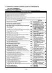
F-3100 SERIES In-line Electromagnetic Flow Meter Installation & Basic Operation Guide 0670-7 / 16958 1500 North Belcher Road, Clearwater, FL 33765 • Tel (727) 447-6140 • Fax (727) 442-5699 www.onicon.com • [email protected] 01-13 1500 North Belcher Road, Clearwater, FL 33765 • Tel (727) 447-6140 • Fax (727) 442-5699 • [email protected] F-3100 Flow Meter Manual 01/13 - 0670-7 Page 2 SAFETY INFORMATION This meter was calibrated at the factory before shipment. To ensure correct use of the meter, please read this manual thoroughly. Regarding this Manual: • • • • • • • • This manual should be passed on to the end user. Before use, read this manual thoroughly to comprehend its contents. The contents of this manual may be changed without prior notice. All rights reserved. No part of this manual may be reproduced in any form without ONICON’s written permission. ONICON makes no warranty of any kind with regard to this material, including, but not limited to, implied warranties of merchantability and suitability for a particular purpose. All reasonable effort has been made to ensure the accuracy of the contents of this manual. However, if any errors are found, please inform ONICON. ONICON assumes no responsibilities for this product except as stated in the warranty. If the customer or any third party is harmed by the use of this product, ONICON assumes no responsibility for any such harm owing to any defects in the product which were not predictable, or for any indirect damages. Safety Precautions: The following general safety precautions must be observed during all phases of installation, operation, service, and repair of this product. Failure to comply with these precautions or with specific WARNINGS given elsewhere in this manual violates safety standards of design, manufacture, and intended use of the product. ONICON Incorporated assumes no liability for the customer’s failure to comply with these requirements. If this product is used in a manner not specified in this manual, the protection provided by this product may be impaired. The following symbols are used in this manual: WARNING ! Messages identified as “Warning” contain information regarding the personal safety of individuals involved in the installation, operation or service of this product. CAUTION ! i Messages identified as “Caution” contain information regarding potential damage to the product or other ancillary products. IMPORTANT NOTE Messages identified as “Important Note” contain information critical to the proper operation of the product. 1500 North Belcher Road, Clearwater, FL 33765 • Tel (727) 447-6140 • Fax (727) 442-5699 • [email protected] F-3100 Flow Meter Manual 01/13 - 0670-7 Page 3 1500 North Belcher Road, Clearwater, FL 33765 • Tel (727) 447-6140 • Fax (727) 442-5699 • [email protected] F-3100 Flow Meter Manual 01/13 - 0670-7 Page 4 TABLE OF CONTENTS 1.0INTRODUCTION ..................................................................................................7 1.1 Purpose Of This Guide.............................................................................. 7 1.2 Principle Of Operation.............................................................................. 7 1.3 Typical Flow Meter Installation ................................................................7 1.4 Standard Features And Specifications...................................................... 8 1.5 Additional Hardware That May Be Required............................................9 1.5.1 Grounding Rings...........................................................................9 1.5.2 Gaskets........................................................................................10 1.6 Working Environment .............................................................................10 1.7 Warranty And Serial Number .................................................................10 2.0UNPACKING .....................................................................................................11 2.1 Checking That You Have Received Everything...................................... 11 3.0INSTALLATION.................................................................................................. 12 3.1 Site Selection ...........................................................................................12 3.1.1 General Guidelines.....................................................................13 3.1.2 Flow Direction............................................................................13 3.1.3 Remote Mount Transmitter........................................................13 3.1.4 Minimum Straight Run Requirements.......................................14 3.2 Mechanical Installation ...........................................................................15 3.2.1 Standard Transmitter Dimensions.............................................15 3.2.2 Sensor Body Dimensions & Weights..........................................16 3.2.3 Installation Drawing For Conductive Pipe................................19 3.2.4 Installation Drawing For Non Conductive Pipe........................21 3.2.5 Installation Drawing For Threaded Connections..................... 22 3.2.6 Installation Instructions ........................................................... 23 3.2.7 Torque Specifications ................................................................25 3.2.8 Remote Mount Transmitter........................................................26 3.3 Electrical Installation ...............................................................................27 3.3.1 Input Power Requirements.........................................................27 3.3.2 Power And Output Signal Wiring Instructions.........................27 3.3.3 Earth Connection........................................................................30 3.3.4 Remote Mount Cable Wiring Instructions.................................31 1500 North Belcher Road, Clearwater, FL 33765 • Tel (727) 447-6140 • Fax (727) 442-5699 • [email protected] F-3100 Flow Meter Manual 01/13 - 0670-7 Page 5 TABLE OF CONTENTS (CONTINUED) 4.0 F-3100 START-UP AND COMMISSIONING .....................................................32 4.1 Display And Keypad Operation...............................................................33 4.2 Helpful Hints For Start-Up And Commissioning ...................................34 4.3 Start-Up And Commissioning..................................................................34 4.4 Start-Up And Commissioning Worksheet................................................35 4.5 Troubleshooting Guide.............................................................................35 4.6 Alarm Interpretation And Standard Led’s...............................................36 APPENDIX A-1 FIELD REMOTE MOUNTING THE TRANSMITTER .......................................38 A-2 CONDITIONS OF SALE.....................................................................................41 1500 North Belcher Road, Clearwater, FL 33765 • Tel (727) 447-6140 • Fax (727) 442-5699 • [email protected] F-3100 Flow Meter Manual 01/13 - 0670-7 Page 6 SECTION 1.0: INTRODUCTION 1.1 PURPOSE OF THIS GUIDE The purpose of this guide is to provide installation and commissioning procedures and basic operating instructions for the F-3100 In-line Electromagnetic Flow Meter. 1.2 PRINCIPLE OF OPERATION The operating principles of ONICON F-3100 In-line Electromagnetic Flow Meters are based on Faraday’s Law of Electromagnetic Induction. Faraday’s Law states that a voltage will be induced in a conductor (water or other conductive liquid) when it passes through a magnetic field (generated by the meter), and the induced voltage will be directly proportional to the velocity of the conductor. By placing electrodes on opposite sides of the flow tube, it is possible to accurately measure the induced voltage and determine the corresponding velocity of the flowing liquid. WARNING ! Only qualified service personnel should attempt to install or service this product. Serious injury may result from the improper installation or use of this product. 1.3 TYPICAL FLOW METER INSTALLATION ONICON’S F-3100 Series In-line Magnetic Flow Meters are suitable for volumetric flow F-3000 Mating Flange Kit of Instructions measurement of Series electrically conductive liquidsGrounding in a wide variety applications including bi-directional applications. INSTALLATION IN STEEL (CONDUCTIVE) PIPE Flow direction Note North 1. 1500 Belcher Road, Clearwater, FL 33765 • Tel (727) 447-6140 • Fax (727) 442-5699 • [email protected] Using #21 Meter (0.159”) drill bit, drill a ½” deep hole in edge of each mating flange. Tap each hole using a 10-32 tap.7 F-3100 aFlow Manual 01/13 - 0670-7 Page Secure the provided ring connectors and grounding wires to the flanges using the provided green grounding screws. (Alternate method: Weld 10-32 studs (not provided) to the flange faces and attach ring connectors with 10-32 nuts (not pro 1.4 STANDARD FEATURES AND SPECIFICATIONS A built-in user interface & display A single 4 – 20 mA output for flow rate Two programmable open collector pulse outputs. Outputs may be programmed to provide: * an indication of flow direction * a scaled pulse for totalizing flow * a high resolution frequency output to drive peripheral devices * an indication of an alarm condition Empty pipe detector Internal self-diagnostic functions & fault alarms CALIBRATION Flow meters are wet calibrated in a flow laboratory against standards that are directly traceable to government standards. A certificate of calibration accompanies every meter. ACCURACY ± 0.4% of reading from 3.3 to 33 ft/sec ± 0.8% of reading from 1 to 3.3 ft/sec ± 0.0075 ft/s at flows less than 1 ft/s PROGRAMMING Factory programmed for specific application MEMORY Nonvolatile memory retains all program parameters and totalized values in the event of power loss. DISPLAY Alphanumeric LCD displays total flow, flow rate, flow direction & alarm conditions OUTPUT SIGNALS Isolated 4 – 20 mA analog output for flow rate Two programmable open collector pulse outputs (configurable for frequency, pulse or directional flow) TEMPERATURE RANGE Liquid temperature range: Polypropylene liner: 32° to 140°F Ebonite liner: 23° to 175°F PTFE liner: -4° to 212° F (266° F with remote electronics) Ambient temperature range: 14° to 122°F MAINTENANCE Periodically inspect the power supply cables, cable glands and the enclosure for signs of damage. Inspect installation and mounting hardware for loose connections. MECHANICAL Electronics Enclosure: Standard: Nylon NEMA 4 Optional: Remote mount transmitter version, maximum distance from the sensor is 65ft. Outer Body Material: Standard: Carbon Steel, Painted Optional: 316 Stainless Steel Flow Tube (Internal): 304 Stainless Steel Connection Type: Standard: ANSI 150 Class Flange Optional: ANSI 300 Class Flange Optional: Wafer Optional: Threaded Process Connection ELECTRICAL This equipment is intended for INSTALLATION CATEGORY (OVERVOLTAGE CATEGORY) II applications. Input Power - Factory Selectable: Standard - 90 to 265 VAC, 45 to 66 Hz, and 35 mA maximum Optional - 10 to 63 VDC, 15 to 45 VAC, 45 to 66 Hz and 300 mA maximum Overcurrent Protective Device Ratings: Supply mains overcurrent protective devices with the following ratings: • 120 VAC 50/60 Hz – 15 A • 230 VAC 50 Hz – 6 A Wiring: Flow signals - Use 18-22 AWG shielded cable Standard input power - Use a three wire service with one wire a protective earth ground. The installation must comply with all local, state and federal building codes. Optional input power - Use PVC jacketed copper cable with a wire gauge suitable for the length of run and required maximum current carrying capacity. The installation must comply with all local, state and federal building codes. PRESSURE AND CONDUCTIVITY Maximum Operating Pressure (Exclusive of flange rating) Ebonite: 1000PSI Polypropylene: 230PSI PTFE: 580PSI Minimum Fluid Conductivity: 5 microsiemens/centimeter Note: Specifications are subject to change without notice. 1500 North Belcher Road, Clearwater, FL 33765 • Tel (727) 447-6140 • Fax (727) 442-5699 • [email protected] F-3100 Flow Meter Manual 01/13 - 0670-7 Page 8 1.5 ADDITIONAL HARDWARE THAT MAY BE REQUIRED 1.5.1 Grounding Rings Grounding rings may be required whenever meters are installed in non-metallic or lined pipes. Grounding rings placed before and after the meter eliminates electrical noise that will interfere with the proper operation of the meter. ONICON provides grounding rings as an optional accessory. Grounding ring dimensional information and part numbers are listed below. For proper operation, grounding rings are required before and after the meter. 5/8 3/8 D 1/4 C Bore 1/8” Nominal Size 1” 1.5” 2” 3” 4” 6” 8” 10” 12” 14” 16” 18” 20” 24” 30” 36” 42” A Grounding Ring Dimensions & ONICON Part Numbers Bore A C D T 1 - 1/16 1 – 9/16 2 – 1/16 3 – 1/16 4 – 1/16 6 8 9 – 1/2 11 – 9/16 13 – 1/2 15 – 1/4 17 – 3/8 19 23 29 35 41 2 - 5/8 3 – 3/8 4 – 1/8 5 – 3/8 6 – 7/8 8 – 3/4 11 13 – 3/8 16 – 1/8 17 – 3/4 20 – 1/4 21 – 5/8 23 - 7/8 28 – 1/4 34 – 3/4 41 – 1/4 48 4 - 9/16 5 - 5/16 6 - 1/16 7 - 5/16 8 - 13/16 10 - 11/16 12 - 15/16 15 - 5/8 18 - 9/16 20 - 3/8 22 - 7/8 24 - 1/4 26 - 11/16 31 - 1/8 38 45 - 1/4 52 - 1/2 1 - 15/16 1 - 15/16 1 - 15/16 1 - 15/16 1 - 15/16 1 - 15/16 1 - 15/16 2 - 1/4 2 - 7/16 2 - 5/8 2 - 5/8 2 - 5/8 2 - 13/16 2 - 7/8 3 - 1/2 4 4 - 1/2 1/8 1/8 1/8 1/8 1/8 1/8 1/8 1/8 1/8 1/8 1/8 1/8 1/8 1/8 1/8 1/8 1/8 316 SS Part # 15212 15213 15214 15215 15216 15217 15218 15219 15220 15221 15222 15223 15224 15225 15226 15227 15228 1500 North Belcher Road, Clearwater, FL 33765 • Tel (727) 447-6140 • Fax (727) 442-5699 • [email protected] F-3100 Flow Meter Manual 01/13 - 0670-7 Page 9 1.5.2Gaskets Gaskets are required for sensor bodies with ebonite and polypropylene liners and are strongly recommended for meters with PTFE liners. Gasket dimensions must comply with ASME B16.5 flange standards. ONICON is not a gasket manufacturer and does not supply gaskets for this product. The following general suggestions are provided to assist the installer in choosing the proper gasket material. In all cases, the responsibility of selecting the appropriate material rests with the installer. Gaskets are used to create a seal between the flow meter liner surface and the surface of the mating flange. The proper choice of gasket material will allow for a leak free connection at the time of installation and maintain that seal over time. How well the gasket works depends on a number of factors. Each of these should be considered when choosing a gasket material. • • • • • Is it chemically compatible with the fluid? Will it withstand the expected minimum and maximum operating temperatures? Does it provide enough resiliency and creep resistance to maintain loading over time? Will it deform enough to create a seal by filling imperfections in the sealing surfaces? Is it thick enough to take up variations in flatness of the surface? In many cases a simple 1/8” red rubber gasket with a Shore A hardness (Durometer) of 60 – 80 will suffice. Your local gasket supplier should be able to guide you in selecting the best material for your application. 1.6 WORKING ENVIRONMENT The F-3100 was designed for installation and use in typical industrial environments that are free of corrosive liquids and fumes, direct liquid exposure, direct sunlight, temperature extremes and vibrations. The operating ambient air temperature range is -4° F to 140° F. The electrical power should be relatively clean, free of high frequency noise, large voltage transients, and protected from power surges and brown outs. 1.7 WARRANTY & SERIAL NUMBER Warranty ONICON’s complete warranty is included in Appendix A of this manual as part of the “Conditions of Sale”. ONICON provides a two-year warranty. Serial Number The F-3100 has 2 separate serial numbers. The transmitter serial number is located on the identification plate located on the electronics enclosure. The sensor serial number is located on the identification plate located on the sensor body. 1500 North Belcher Road, Clearwater, FL 33765 • Tel (727) 447-6140 • Fax (727) 442-5699 • [email protected] F-3100 Flow Meter Manual 01/13 - 0670-7 Page 10 SECTION 2.0: UNPACKING The F-3100 is generally shipped in one package unless optional hardware or equipment is ordered. Notify the freight carrier (all products are shipped insured) and ONICON’s Customer Service Department if any items are damaged in transit. 2.1 CHECKING THAT YOU HAVE RECEIVED EVERYTHING • Standard Documentation Enclosed with each F-3100 is a comprehensive documentation package that includes the following items: Certificate of Calibration The F-3100 Installation and Operation Guide Please notify ONICON if any of these items are missing. F-3100 SERIES In-line Electromagnetic Flow Meter Installation & Basic Operation Guide 1500 North Belcher Road, Clearwater, FL 33765 • Tel (727) 447-6140 • Fax (727) 442-5699 www.onicon.com • [email protected] 0670-1 03-11 FLOW METER CERTIFICATE OF CALIBRATION CALIBRATION & CONFIGURATION DATA for F-3000 SERIES MAGNETIC FLOW METERS METER DATA CALIBRATION of PRIMARY FLOW ELEMENT Meter Tag: CT-WH Ka factor: -1.0951 Model: F-3103-111 Medium: Water Serial Number: 220177 Primary Calibration Date: 4/12/2011 04N1420 38M6901 Component S/N's: Meter Size: 3" Max. Operating Pressure: 225 psi Max. Operating Temperature: 212 °F Connections: ANSI 150# Class Flanges 220177 Peripheral device serial number This meter was manufactured for ONICON Incorporated. The original manufacturer certifies that this flow meter was calibrated against standards that are traceable to SIT, Italy. FACTORY PROGRAMMED OUTPUT SIGNALS (Performed at ONICON Factory; can be reprogrammed in the field) Analog Flow Range: 4-20 mA = 0 to Full Scale Frequency Output: Scaled Pulse Output: 230 Gal/Min 200.00 1 pulse = Programmed By: 100 GL Hz Gallons Date: 5/25/2011 1500 N Belcher Road, Clearwater, Florida 33765 Tel (727)447-6140 Fax (727)442-5699 1500 North Belcher Road, Clearwater, FL 33765 • Tel (727) 447-6140 • Fax (727) 442-5699 • [email protected] F-3100 Flow Meter Manual 01/13 - 0670-7 Page 11 • Integral Mount Transmitter F-3100 In-line Electromagnetic Flow Meters with integrally mounted transmitters are shipped fully assembled. Remove the meter from the shipping carton and inspect it for physical damage. Remote Mount Transmitter • F-3100 In-line Electromagnetic Flow Meters ordered with the remote transmitter mounting option will be shipped in one carton that contains the flow sensor body, the transmitter with mounting hardware and the necessary cable to connect the two together. Remove each and inspect it for physical damage. IMPORTANT NOTE i F-3100 transmitters and sensor bodies are two parts of one uniquely calibrated system and must be installed together. Mixing components from other systems will result in significant calibration errors. • Grounding Rings Grounding rings are optional accessories that may be required for proper installation. Grounding rings may be shipped in a separate carton. Remove each and inspect it for physical damage. SECTION 3.0: INSTALLATION The F-3100 In-line Electromagnetic Flow Meter should be installed by experienced plumbers, electricians and others with related knowledge and experience in the heating, cooling, and fluid metering fields. ONICON will be happy to assist with technical recommendations and to provide guidance by telephone and/or email. On-site field engineering, installation and service are also available at an additional cost. The installer should use good trade practices and must adhere to all state and local building or other applicable codes. 3.1 SITE SELECTION Careful attention during the site selection process will help the installers with the initial installation, reduce start-up problems, and make future maintenance easier. For example, do not install the flow meter where it will be difficult for personnel to perform periodic maintenance. When selecting a site for mounting, consider the criteria under Section 1.6, WORKING ENVIRONMENT, as well as the following: i IMPORTANT NOTE Proper site selection is critical to the performance of this flow meter. The flow meter must be properly located within the piping system in order to ensure an accurate flow measurement. 1500 North Belcher Road, Clearwater, FL 33765 • Tel (727) 447-6140 • Fax (727) 442-5699 • [email protected] F-3100 Flow Meter Manual 01/13 - 0670-7 Page 12 3.1.1 General Guidelines When properly installed, the flow meter will only measure flow associated with that portion of the piping system for which the flow measurement is being made. Choose the location with the longest straight unobstructed run of pipe, keeping in mind that in some applications it may be possible to locate the meter in either the supply or return pipe. 3.1.2 Flow Direction F-3100 flow meters are inherently bi-directional and changes in flow direction are indicated by a change in polarity of the sensing signal. In order for the meter to display the correct polarity, it is necessary to orient the meter relative to flow direction during the installation process. The sign of the flow rate is positive when the flow direction is from – to + as printed on the tag plate as shown below. Prior to installation, determine the direction of flow in the piping system and orient the meter accordingly. - + IMPORTANT NOTE i FLOW DIRECTION Flow direction is indicated by polarity symbols (+/-) and flow totals are accumulated separately based on direction. The polarity of the flow indication may be reversed by reversing the polarity of the Ka coefficient. 3.1.3 Remote Mounted Transmitter Find an easily accessible location where wire connections can be made and meter readings can be taken from floor level. Mount the transmitter on a vibration free surface. Avoid locations that contain electric motors or other strong sources of electrical interference. IMPORTANT NOTE i The F-3100 remote mounted transmitter option is provided without a pre-amplifier. As a result, the maximum distance it can be located away from the sensor body is limited to 65ft. A remote transmitter option with a pre-amplifier is available with the F-3200 advanced transmitter. With this model the remote transmitter may be located up to 1640ft away from the sensor body. Contact ONICON if you need to locate the remote transmitter more than 65ft from the sensor body. 1500 North Belcher Road, Clearwater, FL 33765 • Tel (727) 447-6140 • Fax (727) 442-5699 • [email protected] F-3100 Flow Meter Manual 01/13 - 0670-7 Page 13 3.1.4 Minimum Straight Run Requirements The straight run requirements presented below represent the minimum requirements for accurate flow measurement. For optimum performance, provide as much additional straight run as possible. i IMPORTANT NOTE For proper operation, install the flow meter in a straight run of pipe free of bends, tees, valves, transitions and obstructions for a distance of at least 3 diameters upstream and 2 diameters downstream. Recommended Installation Avoid these installations Place flow meter at least 3 pipe diameters upstream and 2 pipe diameters downstream from bends and obstrutions. 2 DIA 2 DIA 3 DIA Avoid downward flow which can lead to partially filled pipes. 3 DIA 2 DIA 3 DIA Electrode location The electrodes should be located in the horizontal axis (3 o’clock and 9 o’clock) in order to prevent sediment from settling on them. Electrode location Electrode Location 1500 North Belcher Road, Clearwater, FL 33765 • Tel (727) 447-6140 • Fax (727) 442-5699 • [email protected] F-3100 Flow Meter Manual 01/13 - 0670-7 Page 14 3.2 MECHANICAL INSTALLATION i IMPORTANT NOTE F-3100 transmitters and sensor bodies are two parts of one uniquely calibrated system and must be installed together. Mixing components from other systems will result in significant calibration errors. 3.2.1 Standard Transmitter Dimensions Net weight 1.6 lbs 3” 2.5” Install sensor cable here 0.25” Diameter 1500 North Belcher Road, Clearwater, FL 33765 • Tel (727) 447-6140 • Fax (727) 442-5699 • [email protected] F-3100 Flow Meter Manual 01/13 - 0670-7 Page 15 3.2.2 Sensor Dimensions & Weights Ansi Class 150 Flanged Sensor Overall Dimension H D L Shown with 4-bolt pattern Sensor Size Nominal Diameter 1” 1.25” 1.5” 2” 2.5” 3” 4” 5” Lenght (L above) 7.87 7.87 7.87 7.87 Height (H above) 7.13 7.55 8.15 8.74 Flange Dia (D above) 4.24 46.4 5.00 Weight in lbs 6.6 9.7 11 6” 8” 10” 12” 7.87 7.87 9.84 9.84 9.64 10.20 11.34 12.40 13.43 15.79 18.15 20.75 5.98 7.00 7.52 9.02 10.00 10.98 13.50 15.98 19.02 15.4 21.5 26.4 32.0 35.2 11.81 13.78 17.72 19.68 55 75 138 159 Sensor Size Nominal Diameter Length (L above) 14” 16” 18” 20” 24” 26” 30” 34” 36” 42” 48” 21.65 23.62 23.62 23.62 23.62 25.59 29.53 33.46 35.43 39.37 47.24 Height (H above) 22.91 25.16 27.08 29.57 34.09 36.26 40.63 45.24 47.48 54.37 58.66 Flange Dia (D above) 20.98 23.50 25.00 27.52 32.01 34.25 38.74 43.74 45.98 52.99 57.28 238 341 407 462 664 770 911 1210 1386 1716 1948 Weight in lbs 1500 North Belcher Road, Clearwater, FL 33765 • Tel (727) 447-6140 • Fax (727) 442-5699 • [email protected] F-3100 Flow Meter Manual 01/13 - 0670-7 Page 16 Wafer Style Sensor Overall Dimensions G 0.95" H D L I.D. Sensor Size 1” 1.25” 1.5” 2” 2.5” 3” 4” 5” 6” 8” 10” 12” 14” 16” L 3.94 3.94 3.94 3.94 5.90 5.90 5.90 7.09 7.09 7.87 9.84 11.81 13.78 15.75 H 5.79 6.02 6.34 6.97 7.83 8.23 9.25 10.35 11.46 14.25 16.42 18.39 20.75 22.80 D 2.20 2.44 2.76 3.39 4.25 4.65 5.67 6.77 7.87 10.67 12.83 14.80 17.17 19.21 G - - - - - - - - - 5.67 7.64 9.60 11.57 13.54 2.6 3.5 4.0 4.4 7.9 8.4 11 17.2 18 40 53 59 70 86 Nominal Dia Net Weight in lbs Threaded Version H Weight L H W Polypropylene 4.85 lbs 5.5” 7.4” 3.8” Stainless Steel 4.85 lbs 4.72” 6.69” 3.07” L W 1500 North Belcher Road, Clearwater, FL 33765 • Tel (727) 447-6140 • Fax (727) 442-5699 • [email protected] F-3100 Flow Meter Manual 01/13 - 0670-7 Page 17 Recommended method for lifting all sensors with eyebolts The eyebolts are designed to hold only the weight of the meter WARNING ! Eyebolts are provided to assist in the safe installation of meters with a nominal diameter greater than 6 inches. The eyebolts are only designed to hold the weight of the meter. Do not attempt to place an additional load on the eyebolts during installation. 1500 North Belcher Road, Clearwater, FL 33765 • Tel (727) 447-6140 • Fax (727) 442-5699 • [email protected] F-3100 Flow Meter Manual 01/13 - 0670-7 Page 18 F-3000 Series Mating Flange Grounding Kit Instructions 3.2.3 Installation Drawings for Conductive Pipe Note 2. INSTALLATION IN STEEL (CONDUCTIVE) PIPE Flow direction Note 1. Note 1. Note 3. Note 1. Note 1. Using a #21 (0.159”) drill bit, drill1a ½” deep hole in edge of each mating flange. Tap each hole in edge ofand each matingwires flange. Tap each a #using 21 (0.159") drillSecure bit, drill 2 " deep Using hole a 10-32 tap. the a ring connectors (provided) grounding to the flange hole a 10-32 tap. grounding Secure the ring(provided). connectors (provided) and grounding wires to the flange u usingusing the green screws the green grounding screws (provided). (Alternate method: Weld10-32 10-32 studs provided) to the faces and attach ring (Alternate method : Weld studs(not (not provided) to flange the flange faces andring attach connectors with 10-32 nuts(not (not provided). provided). connectors with 10-32 nuts Note 2. Provide a ground connection at the input power terminals inside the transmitter enclosure. Note 2. Provide a ground connection atconnection the input to power terminals inside the transmitter enclosure. Note 3. Provide a quality earth ground the meter. 3. best to worst, grounding options include: NoteFrom Earth grounding rod driven into the to soil. Provide a1.quality earth ground connection the meter. 2. Earth wire connected directly to the building electrical service panel. From best to worst, grounding options include: 3. Earth wire connection inside an electrical outlet mear the meter. 1. Earth grounding rod driven into the soil. 2. Earth wire connected directly to the building electrical service panel. 3. Earth wire connection inside an electrical outlet near the meter. CAUTION ! The earth connections must be made as shown. Failure to do so will result in erratic operation of the meter. 1500 North Belcher Road, Clearwater, FL 33765 • Tel (727) 447-6140 • Fax (727) 442-5699 • [email protected] F-3100 Flow Meter Manual 01/13 - 0670-7 Page 19 (Wafer Style Meter) Note 3. INSTALLATION IN CONDUCTIVE PIPE Note 2. Flow direction Note 1. Note 1. Note 4. Note 1. Note 1. Usingaa##21 drill bit,bit, drilldrill a ½”1a2deep holehole in edge of eachof mating Tapflange. each Tap each " deep in edge eachflange. mating Using 21(0.159”) (0.159") drill holeusing using a a 10-32 Secure the ring (provided) and grounding to the flange to the hole 10-32tap. tap. Secure theconnectors ring connectors (provided) andwires grounding wires using the green grounding screws (provided). flange using the green grounding screws (provided). (Alternate method : Weld 10-32 studs (not provided) to the flange faces and attach ring (Alternate method: Weld 10-32 studs (not provided) to the flange faces and attach ring connectors with 10-32 10-32 nuts provided). connectors with nuts (not(not provided). Note 2. For 2. meters provided with a grounding electrode connect grounding wire to terminal on the Note meter neck as shown. For meters provided with a grounding electrode connect grounding wire to terminal on the meter neck as shown. Note 3. Provide a ground connection at the input power terminals inside the transmitter enclosure. Note 4. From Note 3.best to worst, grounding options include: grounding rod driven into input the soil. Provide1.aEarth ground connection at the power terminals inside the 2. Earth wire connected directly to the building electrical service panel. Note 4.3. Earth wire connection inside an electrical outlet mear the meter. ! transmitter enclosure. From best to worst, grounding options include: 1. Earth grounding rod driven into the soil. 2. Earth wire connected directly to theCAUTION building electrical service panel. 3. Earth wire connection inside an electrical outlet near the meter. The earth connections must be made as shown. Failure to do so will result in erratic operation of the meter. 1500 North Belcher Road, Clearwater, FL 33765 • Tel (727) 447-6140 • Fax (727) 442-5699 • [email protected] F-3100 Flow Meter Manual 01/13 - 0670-7 Page 20 3.2.4 Installation Drawing for Non-Conductive Pipe INSTALLATION IN NON CONDUCTIVE PIPE (EXPLODED VIEW) GASKET (4PL) Flow Direction GROUNDING RING (2PL) 1500 North Belcher Road, Clearwater, FL 33765 • Tel (727) 447-6140 • Fax (727) 442-5699 • [email protected] F-3100 Flow Meter Manual 01/13 - 0670-7 Page 21 WAFER INSTALLATION IN NON-CONDUCTIVE PIPE GASKET GROUNDING RING GASKET Flow Direction CAUTION ! The earth connections must be made as shown. Failure to do so will result in erratic operation of the meter. 3.2.5 Installation Drawing for Threaded Connections ! CAUTION The earth connections must be made as shown. Failure to do so will result in erratic operation of the meter. 1500 North Belcher Road, Clearwater, FL 33765 • Tel (727) 447-6140 • Fax (727) 442-5699 • [email protected] F-3100 Flow Meter Manual 01/13 - 0670-7 Page 22 3.2.6 Installation Instructions ! WARNING Installation of this product should only be attempted by qualified tradespersons and must comply with all local, state and federal building codes. 1. Thoroughly clean all flange surfaces removing all traces of any old gasket material or any adhesive residue. 2. Inspect all flange surfaces for warping, pitting or other surface imperfections that may prevent a good seal. 3. Use new bolts, nuts and hardened washers. ONICON recommends the use of B7 nuts, bolts and washers. Prior to installation, lubricate the bolt threads, nuts, washer faces and the underside of the bolt head with lubricant (Fel Pro C5A or equivalent). This lubricant is necessary to ensure uniform stress distribution on the sealing surface. Use care not to get any lubricant on the liner or gasket material. 4. Center the new gasket on the liner surface. Do not allow the gasket to protrude into the flow stream. 5. Use the torque specifications shown below to determine the recommended final bolt torque requirements. 6. Using a torque wrench, tighten the bolts in at least three stages (30%, 60% & 100%) using a repeating pattern sequence shown in the diagrams below. ANSI Class 150 Flange Bolt Tightening Sequence Liner material 1500 North Belcher Road, Clearwater, FL 33765 • Tel (727) 447-6140 • Fax (727) 442-5699 • [email protected] F-3100 Flow Meter Manual 01/13 - 0670-7 Page 23 ANSI Class 150 Flange Bolt Tightening Sequence 1500 North Belcher Road, Clearwater, FL 33765 • Tel (727) 447-6140 • Fax (727) 442-5699 • [email protected] F-3100 Flow Meter Manual 01/13 - 0670-7 Page 24 3.2.7 Torque Specifications Tighten uniformly in a diagonal sequence as per the table below. Contact ONICON for torque specifications for meters with a nominal diameter larger than 24 inches. Torque Specifications in ft-lb Operating Pressure PSI Dia. 140 PTFE EBON 260 PTFE EBON 350 PP PTFE EBON 600 PTFE EBON 1000 EBON 1” 19 14 19 19 29 1.25” 32 21 32 32 40 1.5” 40 27 40 40 54 2” 51 39 51 51 60 2.5” 67 56 34 34 63 3” 40 31 40 40 46 4” 44 42 62 62 65 5” 57 53 83 83 110 6” 80 79 100 100 161 8” 110 91 73 61 99 83 132 110 172 10” 91 76 104 87 151 126 197 165 237 12” 105 88 130 108 149 124 205 172 234 14” 127 106 152 127 239 200 312 260 355 16” 161 134 208 174 315 262 457 381 460 18” 144 119 208 173 20” 166 138 282 235 24” 239 199 419 350 1500 North Belcher Road, Clearwater, FL 33765 • Tel (727) 447-6140 • Fax (727) 442-5699 • [email protected] F-3100 Flow Meter Manual 01/13 - 0670-7 Page 25 3.2.8 Remote Mount Transmitter Remote mount transmitters are provided with a single “L” bracket with two ¼” mounting holes. The bracket is secured to the transmitter by means of a large bolt with a knurled knob for a head. To mount the bracket, first separate it from the transmitter housing and attach it to the wall or other vertical surface. Cable from the sensor body is attached to the transmitter using the center strain relief. Cable is supplied already attached to the sensor body. Mounting Bracket Cable wires are labeled with numbers which correspond to connection terminals on the transmitter. CAUTION ! DO NOT drill holes in the transmitter. Use only the openings that are provided. DO NOT cut the remote cable. Coil excess cable at one end. 3” 2.5” 1” 0.25” DIA Insert 2.5” Install sensor cable here 0.25” Diameter 1500 North Belcher Road, Clearwater, FL 33765 • Tel (727) 447-6140 • Fax (727) 442-5699 • [email protected] F-3100 Flow Meter Manual 01/13 - 0670-7 Page 26 3.3 ELECTRICAL INSTALLATION 3.3.1 Input Power Requirements F-3000 Electromagnetic Flow Meters equipped with standard transmitters are available with two different options for input power. This is not a user selectable function and must be configured at the factory. Special care is required to ensure that the F-3100 is properly connected to earth through an earth wire. This connection is required to prevent random electrical noise from interfering with the operation of the meter. (See section 3.3.3 for details.) * Low Voltage: 10 – 63 VDC, 15 – 45 VAC 45/66 Hz, 300 mA maximum * High Voltage (Mains): 90 – 265 VAC 45/66 Hz, 35 mA maximum IMPORTANT NOTE i This option is not field selectable. Contact the factory if you need to change the input voltage rating. CAUTION/WARNING ! This product must be connected to earth ground for proper operation. Failure to do so will result in erratic operation and an increased risk of injury. WARNING ! All mains voltage connections must be made through pre-drilled conduit/strain relief opening located at the bottom of the enclosure. Failure to do so will result in an increased risk of injury. 3.3.2 Power and Output Signal Wiring Instructions Factory Default Output Configurations ONICON pre-programs the analog and pulse outputs based on application specific data provided at the time the meter is ordered. The table below shows how the pulse outputs are configured based on whether the application has bi-directional flow and if the meter will be connected to an ONICON peripheral device such as an ONICON Btu meter or display module. In all applications the analog 4-20 mA output is available at terminals 9 (+) and 10 (-). Application Standard Bi-directional Pulse Output #1 Terminals: 16 (+) & 17 (-) Frequency *Scaled Output Pulse Output #2 Terminals: 18 (+) & 19 (-) Scaled Pulse Flow Direction * This output will be configured for frequency if the flow meter is provided with a peripheral device. 1500 North Belcher Road, Clearwater, FL 33765 • Tel (727) 447-6140 • Fax (727) 442-5699 • [email protected] F-3100 Flow Meter Manual 01/13 - 0670-7 Page 27 Step 1: Loosen screws to lift cover. Step 2: Lift cover to expose electrical connections. Step 3: Make SIGNAL connections as shown Pull straight out on connectors to remove them. POWER CONNECTIONS SIGNAL CONNECTIONS 4-20 mA Output Pin 9 - Pos (+) Pin 10 - Neg (-) Pulse Out 2 Pin 18 - Pos (+) Pin 19 - Neg (-) Step 4: Open cover to expose POWER Connections. Pulse Out 1 Pin 16 - Pos (+) Pin 17 - Neg (-) Remove retaining screw to expose connector. (Shown with High Voltage) Power connections are under this cover. Pulse Output 1 / Pulse Output 2 Opto-coupled open collector pulse outputs Maximum voltage: 40VDC Maximum current: 100mA Maximum saturation voltage collector/emitter @ 100mA: 3 VDC 0516 5-15-08 1500 North Belcher Road, Clearwater, FL 33765 • Tel (727) 447-6140 • Fax (727) 442-5699 • [email protected] F-3100 Flow Meter Manual 01/13 - 0670-7 Page 28 POWER CONNECTIONS CONTINUED Step 5: Pull straight out on the connector to remove it. Low voltage version High voltage version Step 6: Wire the connector as shown based on input type. Earth connection must be made. _ L + N Step 7: Use the right hand strain relief for installing the power cable or power conduit. 3-13-08 1500 North Belcher Road, Clearwater, FL 33765 • Tel (727) 447-6140 • Fax (727) 442-5699 • [email protected] F-3100 Flow Meter Manual 01/13 - 0670-7 Page 29 3.3.3 Earth Connection F-3100 Electromagnetic Flow Meters are designed to detect microvolt signal levels at the electrodes located in the flow meter body. These signals are generated as conductive fluids flow through the magnetic field generated by the meter. If enough random electrical noise is present at the electrodes, it can interfere with the flow measurement. Care must be taken during installation to minimize the effects of electrical noise on the flow meter. The most effective way to minimize the effects of electrical noise is to make sure that the pipe, fluid, flow meter body and flow meter transmitter are all connected to the same earth ground. This accomplishes two important goals. First, it ensures that the pipe, fluid, flow meter body and electronics are all at the same electrical potential, and second, it ensures that this electrical potential is the same as earth ground. In order to be certain that the meter is properly connected to earth, the flow meter body earth connections (at the flanges or on the neck of wafer meters) and the transmitter earth connection should be run directly to a known earth connection. The length of this earth cable should be as short as practically possible, preferably ≤25 feet in length. The table below lists earth connections from best to worst. i ! IMPORTANT NOTE Non-metallic pipes are more susceptible to electrical noise. Grounding rings installed upstream and downstream of the flow meter body to reduce the electrical noise present in the pipe may be required for proper operation. CAUTION Do not use bolts that hold pressure to make earth connections. Using flange bolts may result in poor electrical connections due to the presence of paint and/or lubricants. Use the dedicated flange earth connections or the dedicated earth connection on the neck of wafer style meters. Earth Connections (stranded wire 14 - 18 AWG) Best Earth grounding rod driven into the ground. Earth wire connected directly to the building electrical service panel. Worst Earth wire connection inside an electrical outlet near the meter. 1500 North Belcher Road, Clearwater, FL 33765 • Tel (727) 447-6140 • Fax (727) 442-5699 • [email protected] F-3100 Flow Meter Manual 01/13 - 0670-7 Page 30 3.3.4 Remote Mount Cable Wiring Instructions ! Caution Do not cut the remote mount cable. The wires are not color coded. Cable wires are labeled with numbers which correspond to connection terminals on the transmitter. Install remote cable through the center strain relief as shown. Connect the coil and electrode wires to the appropriate terminals according to the numbered tags on each wire. 1500 North Belcher Road, Clearwater, FL 33765 • Tel (727) 447-6140 • Fax (727) 442-5699 • [email protected] F-3100 Flow Meter Manual 01/13 - 0670-7 Page 31 SECTION 4.0: METER START UP & COMMISSIONING FOR ONICON F-3100 SERIES FLOW METERS 1500 North Belcher Road, Clearwater, FL 33765 • Tel (727) 447-6140 • Fax (727) 442-5699 • [email protected] F-3100 Flow Meter Manual 01/13 - 0670-7 Page 32 4.1 DISPLAY AND USER INTERFACE The F-3100 standard transmitter is equipped with a 2 line by 16 character LCD with 0.2” high characters. Three pushbutton switches located inside the transmitter enclosure are used to change the displayed data and program the meter functions. Momentarily press the UP (top) button to view alarm messages. Momentarily press the RIGHT (middle) button to advance to the next menu page. The ENTER (bottom) button is used in programming. Flow Rate Flow Direction Indicator Percentage of Full Scale Engineering Units Partial Positive Flow Total Flow Rate Partial Positive Flow Total Total Positive Flow Total Total Negative Flow Total Partial Negative Flow Total Positive Flow Total Negative flow Total Flow Rate Flow Velocity Flow Rate Partial Negative Flow Total When selected, this page will cause the menu pages to scroll automatically. =======> <======= 1500 North Belcher Road, Clearwater, FL 33765 • Tel (727) 447-6140 • Fax (727) 442-5699 • [email protected] F-3100 Flow Meter Manual 01/13 - 0670-7 Page 33 4.2 HELPFUL HINTS FOR START-UP AND COMMISSIONING A step-by-step procedure and companion worksheet are located on the next two pages. Please read all installation instructions and these helpful hints carefully before proceeding with installation, start-up and commissioning. 1. ONICON flow meters are individually calibrated for a particular application. Be sure to verify the pipe size and location. 2. The electronic sensing system will not work in air. The pipe must be full for proper operation. 3. When measuring analog output signals, remember that currents (mA) must be measured in series, while voltages are measured in parallel. If the 4-20 mA signal is already connected to a control system, you must break the connection and measure the signal in series. 4. When measuring frequency outputs in hertz, take your multimeter out of “autorange mode” and manually set range for a voltage level above 15 VDC. This will prevent false readings when signal is not present. 5. Never connect power to analog or frequency output signal wires. ONICON F-3100 Flow Meters are not “loop powered” devices. 4.3 START-UP AND COMMISSIONING Please read the entire procedure carefully before proceeding. Wiring instructions are located on pages 21 - 24 of this manual. A worksheet for checking off the following steps and recording measured values is located on the next page. 1. Confirm flow meter location and adequate straight pipe run to achieve desired results. Is the meter located in the correct location as required by the plans? Compare actual straight pipe upstream and downstream of the meter location to recommended distances identified in this manual. 2. Confirm control system programming. Confirm that the control system input point is properly configured for the analog range (or scale factor) identified on the calibration certificate. 3. Confirm connection to correct ONICON display or Btu meter (if ordered). Confirm that the flow meter serial number matches the ONICON display or Btu meter serial number (when ordered together). 4. Verify wiring before connecting power. Prior to connecting the power, verify that the wiring is correct as shown in this manual and/ or the additional wiring diagram provided with ONICON display or Btu meter. If in doubt, contact ONICON for assistance before proceeding further. 5. Verify that the input voltage available to power the meter is appropriate for the meter version. (Check label inside transmitter enclosure LV=Low voltage, HV=High voltage. Low voltage: 10 - 63 VDC or 15 - 45 VAC 45/66 Hz, 300 mA maximum Connect power. Wait approximately 45 seconds after power-on before proceeding further. 6. High voltage: 90 - 265 VAC 45/66 Hz, 35 mA maximum The following steps require flow in the pipe. Flow signal readings should be taken while holding the flow rate constant if possible. Otherwise, take the various output readings as quickly as possible. 7. Measure and record analog or binary outputs. Current Output: Scaled Output: 8. Compare various output signals to each other and to the flow rate displayed and to the control system. Refer to flow meter wiring diagram for the various outputs available based on your particular flow meter model. Use the following formulas to calculate flow rate from measured analog signals: GPM = (measured current in mA - 4) X Full Scale Analog Flow Rate 16 Each contact closure = unit volume identified as “Scale Factor” (measure and record time interval between contact closures) Compare the flow rates calculated in STEP 7 to the flow rate indicated by the display and the control system. Refer to troubleshooting guide when readings are inconsistent. 1500 North Belcher Road, Clearwater, FL 33765 • Tel (727) 447-6140 • Fax (727) 442-5699 • [email protected] F-3100 Flow Meter Manual 01/13 - 0670-7 Page 34 4.4 START-UP AND COMMISSIONING WORKSHEET Please read all installation instructions carefully prior to proceeding with these steps. Use the following worksheet for checking off the commissioning steps and recording measured values. STEP TEST/MEASUREMENT 1. Meter location: 2. Control system programming: 3. Match display or Btu meter serial # (S/N) if ordered: 4. Signal connections verified: 5. Supply voltage verified: 6. Connect power: S/N: _________ S/N: ________ S/N: ________ S/N: _________ The following steps require flow in the pipe. Flow signal readings should be taken while holding the flow rate constant if possible. Otherwise, take the various output readings as quickly as possible. 10. 11 Analog or binary outputs 4-20 mA signal: ________ mA ________ mA ________ mA ________ mA scaled output interval ___________ ___________ ___________ ___________ Calculated flow rate: _______ GPM _______ GPM _______ GPM _______ GPM Flow rates displayed on meter display: _______ GPM _______ GPM _______ GPM _______ GPM control system: _______ GPM _______ GPM _______ GPM _______ GPM 4.5 TROUBLESHOOTING GUIDE NOTE: Also refer to the START-UP AND COMMISSIONING GUIDE located on the preceeding pages. REPORTED PROBLEM POSSIBLE SOLUTIONS No signal • Verify correct wiring to control system (See wiring diagram.) • Check display for alarm messages. Verify that the pipe is full. • Verify that the sensor body and transmitter are both connected to earth ground. Reading is too high or low • Verify correct wiring to control system (see wiring diagram). • Confirm that the output signals are consistent (frequency vs. analog, etc). • Confirm that the control system is programmed for correct flow range or scale factor. Analog signal seems high or Check for ground loop or offset voltage: low and does not correspond • Verify that the sensor body and transmitter are both connected to earth ground. to frequency output • Disconnect analog signal input from control system and measure analog outputs directly from the flow meter. • Re-connect signal input to control system and measure the analog signals again. • Any difference between these readings indicates a potential ground loop or offset voltage. • Please contact ONICON for further assistance. Control system displays flow rate, but no flow rate is indicated on the local display module or Btu meter • Verify that all of the wires from the flow meter are connected to the display module or Btu meter. • The frequency output wire (green) must be connected for any ONICON display or Btu meter. 1500 North Belcher Road, Clearwater, FL 33765 • Tel (727) 447-6140 • Fax (727) 442-5699 • [email protected] F-3100 Flow Meter Manual 01/13 - 0670-7 Page 35 4.6 ALARM INTERPRETATION AND STATUS LED’s ALARMS ALARMS Alarm Indicators Description When activated, this symbol indicates flow in excess of the set point. Range: 0-125% of full scale INTERPRETATION ALARMS When activated, this symbol indicates flow below the ALARM set point. DESCRIPTION M Alarm max activated Range: 0-125% of full scale m Alarm min activated • Open coil connection - Interruption coils circuit ! Segnal error • Signal error - Empty pipe • When activated, indicates empty pipe. C Calibration running Calibration S Simulation running Pulse output saturation (reduceoutput mode Transmitter in simulated TIME PULSE ) Pulse output saturated (change pulse rate or duration) Symbol M m ! C S W LED 11 12 13 14 15 16 17 18 19 20 1 2 3 4 5 6 7 8 9 10 Status LED LED INTERPRETATION Continuously ON: Initialization of firmware PERMANENT LIGHT: initialisation Flashing LED: (1 second rate): Normal operation FLASHING LIGHT ( 1 sec.): normal function Flashing LED: (<1 second rate): Alarm condition FLASHING LIGHT (<1 SEC.): alarm on The LED signals the real alarm status only if the display visualizes one of the visualization to page 17 • Fax (727) 442-5699 • [email protected] 1500 North Belcher Road, Clearwater, FL 33765pages • Tel suitable (727) 447-6140 F-3100 Flow Meter Manual 01/13 - 0670-7 Page 36 APPENDIX A-1 A-2 FIELD REMOTE MOUNTING THE TRANSMITTER CONDITIONS OF SALE 1500 North Belcher Road, Clearwater, FL 33765 • Tel (727) 447-6140 • Fax (727) 442-5699 • [email protected] F-3100 Flow Meter Manual 01/13 - 0670-7 Page 37 Field Remote Mounting the Transmitter Wiring Instructions Section 1: Removing the Transmitter Before attempting to remote mount the transmitter, disconnect power at the source. Step 1 Open cover. Slide cover off to the right, if desired. Step 3 Remove power connector from its socket. Remove wires from the connector and set aside. Step 5 Remove electrode and coil wires from connectors and set aside. Step 2 Open compartment to expose power connection. Step 4 Remove electrode and coil connectors from their sockets. Step 6 Remove mounting screws from the bottom of the enclosure. Screws do not need to be fully removed. Step 7 Carefully separate the electronics enclosure from the sensor body. As the two come apart, feed the sensor wires through the opening in the bottom of the enclosure. 1500 North Belcher Road, Clearwater, FL 33765 • Tel (727) 447-6140 • Fax (727) 442-5699 • [email protected] F-3100 Flow Meter Manual 01/13 - 0670-7 Page 38 Section 2: Installing the Remote Mount Junction Box Step 1 Remove the cover and circuit board from the remote mount junction box. Step 3 Re-install the circuit board. Step 2 Feed the cales through the holes in the bottom of the junction box and mount it in place. Step 4 Attach the cables to the terminal blocks as shown. (Note: Each wire is labeled with a number that corresponds to a terminal location.) Step 5 Install the remote mount cable through the strain relief supplied with the junction box. Step 7 Cables should be connected as shown. Step 6 Install the remote mount cable to the numbered terminal block positions. Sensor cables Step 8 Re-install the cover. Remote transmitter cable 1500 North Belcher Road, Clearwater, FL 33765 • Tel (727) 447-6140 • Fax (727) 442-5699 • [email protected] F-3100 Flow Meter Manual 01/13 - 0670-7 Page 39 Section 3: Wiring the Transmitter Step 1 Remove the retaining nut and black plastic plug from the center strain relief on the enclosure and feed the nut over the end of the cable. Then feed the cable through the strain relief. Step 2 Attach the green connectors to the end of the cable. Numbers on each wire correspond to the numbers on the connectors. Step 3 Re-install the connectors and tighten the strain relief. Re-install the power cable and connector. Step 4 Remove the o-ring from the remote mount bracket and place it into the gland on the bottom of the enclosure as shown. Step 5 Attach the mounting bracket using the screws and lock washers supplied in the kit. Step 6 Close and fasten the cover. i IMPORTANT NOTE Transmitter programming must be changed to complete the remote mount installation. 1500 North Belcher Road, Clearwater, FL 33765 • Tel (727) 447-6140 • Fax (727) 442-5699 • [email protected] F-3100 Flow Meter Manual 01/13 - 0670-7 Page 40 CONDITIONS OF SALE 1. ACCEPTANCE: The following Conditions of Sale apply to all sales of ONICON’s products. These provisions shall apply even if ONICON fails to object to provisions appearing on, incorporated by, referenced in, or attached to Buyer’s purchase order form. Buyer’s acceptance of delivery of ONICON’s products constitutes its acceptance of these Conditions of Sale. 2. DELIVERY AND TITLE: All product shipments are F.O.B. shipping point and title passes to the Buyer at the time ONICON delivers the merchandise to the carrier. Risk of loss or damage to the product passes to the Buyer at the time ONICON delivers the product to the carrier. The Buyer immediately upon receipt should inspect all shipments, and should there be any evidence of damage or loss in transit, Buyer must file claims or tracers upon carrier. ONICON will assist in tracing shipments upon request. 3. LIMITED WARRANTY: ONICON warrants that for a period of two (2) years following the date of original shipment of an ONICON product: (i) the product will conform to ONICON’s standard written specifications applicable to such product in effect on the date of Buyer’s order, or as modified by ONICON’s quotation or Buyer’s purchase order accepted by ONICON, (ii) the product will be free from defects in workmanship, and (iii) that ONICON has title to the product prior to shipment to the Buyer; provided, however, that the warranties provided herein shall be void and may not apply in the event Buyer misuses or damages a product, including, but not limited to, any use by the Buyer of a product for an application other than one of a type approved by ONICON. ONICON’s sole liability and Buyer’s sole remedy for any breach of the foregoing warranty is for ONICON to repair or replace, at ONICON’s option, any defective product that is returned to ONICON during the warranty period. EXCEPT AS MAY BE SPECIFICALLY AGREED BY ONICON IN WRITING IN RELATION TO EACH SALE, NO OTHER WARRANTIES SHALL APPLY, WHETHER EXPRESSED, IMPLIED OR STATUTORY, AND THERE SHALL BE NO IMPLIED WARRANTIES OF MERCHANTABILITY AND FITNESS FOR A PARTICULAR PURPOSE. 4. REMEDIES: ONICON’s OBLIGATION UNDER THE FOREGOING WARRANTIES IS LIMITED SOLELY TO REPAIR OR REPLACEMENT, AT ONICON’s OPTION, OF DEFECTIVE OR NONCONFORMING PRODUCTS. ONICON SHALL NOT BE LIABLE FOR CONSEQUENTIAL, INDIRECT, PUNITIVE, INCIDENTAL, OR SPECIAL DAMAGES WHETHER FOUND ON CONTRACT, TORT OR ANY OTHER THEORY OF LAW. No products shall be returned to ONICON without its prior consent and transportation and insurance costs shall be prepaid. Any repair or replacement of ONICON’s products under the foregoing warranty will be at no charge to the Buyer provided such repair is done at the ONICON factory or authorized service center. ONICON products that are repaired or replaced under this warranty will be returned to Buyer via the same method of shipment use to return the product to ONICON. Repair or replacement of ONICON products is conditioned upon ONICON’s acknowledgement of any alleged defect or nonconformance during the warranty period and issuance of a Return Authorization number. All product returns must reference the Return Authorization number on the outside of the shipping carton and on any paperwork referencing the return. 5. PRICES AND PAYMENT TERMS: The prices set forth in the most recent quote or acknowledgement as applicable, supersede all previous prices or quotations. All quotations are subject to change or withdrawal without notice except as may be specifically noted on the face of the quotation. The prices shown do not include sales, excise or government charges payable by ONICON to Federal, State, or local authority. Any such tax or charge now or hereafter imposed upon the sale or shipment of the products under this contract will be added to the purchase price. Buyer agrees to reimburse ONICON for such tax or charge or provide ONICON with an acceptable exemption certificate. Payment of invoices will be due 30 days from the date of shipment of the products contained therein. In the event that payment of an invoice is not received by the invoice due date, ONICON will assess a late fee not to exceed 1.5% per month or 18% per year, or the maximum allowableby law whichever is lower. 6. CANCELLATION: Buyer may cancel its order, or any part of it, by sending written notice of cancellation to ONICON and paying a reasonable cancellation fee as determined by ONICON. The reasonable cancellation fee will reflect, among other factors, the expenses already incurred and commitments made by ONICON, sales and administrative costs and profit as determined by ONICON. If Buyer received a reduced price based on the quantity of products ordered, but has not purchased the applicable quantity at the time of cancellation, Buyer will pay the price it would have paid had ONICON’s sale price been based on the quantity actually purchased. 7. CHANGES: If Buyer makes any changes in its drawings, designs, or specifications applicable in any contract with ONICON that cause an increase or decrease in the cost of performance of the contract, or if such changes result in rework or obsolescence, an equitable adjustment shall be made to the contract. Such changes are subject to ONICON’s prior written consent. 8. EXCUSABLE DELAY: ONICON shall under no circumstance be responsible for failure to fill any order or orders when due to: fires, floods, riots, strikes, freight embargoes or transportation delays, shortage of labor, inability to secure fuel, material supplies, or power at current price or on account of shortages thereof, acts of God or of the public enemy, any existing or future laws or acts of the Federal or State Government (including specifically, but not exclusively, and orders, rules or regulations issued by any official or agency of any such government) affecting the conduct of ONICON’s business with which ONICON in its judgment and discretion deems it advisable to comply as a legal or patriotic duty, or due to any cause beyond ONICON’s reasonable control. 9. 10. PATENTS: ONICON shall defend all suits or proceedings brought against Buyer or its customers arising from claimed infringements of any patent, trademark, service mark or copyright for any product furnished by ONICON and shall indemnify it against all costs, fees, and damages on the condition Buyer promptly notifies ONICON in writing and provides information and assistance to enable ONICON to conduct the defense, provided that ONICON shall have no such obligation in case of infringement resulting from ONICON’s conformance to special requirements of Buyer. If ONICON is not able to settle any such suit or proceeding on acceptable terms, ONICON may, at its option, require return of the infringing product and refund the purchase price to Buyer less a reasonable allowance for depreciation or use. 11. APPLICABLE LAW: This document and any resulting contract shall be governed by and construed in accordance with the laws of the State of Florida. The courts of the State of Florida and the federal courts located in Florida shall have jurisdiction and venue with respect to litigation to this contract. In the event of litigation, the prevailing party shall be entitled to recover attorney’s fees and costs from the non-prevailing party, including appellate attorney’s fees. FAIR LABOR STANDARDS ACT: ONICON represents that all products delivered under this contract are furnished in accordance with the applicable provisions of the Fair Labor Standards Act as amended. 12. MODIFICATIONS: These Conditions of Sale along with the prices, quantities, delivery schedules and other provisions and instructions in applicable quotations by ONICON or Buyer’s purchase orders accepted by ONICON shall constitute the entire agreement between ONICON and Buyer pertaining to any resulting contract. They can be modified only in writing. 1500 North Belcher Road, Clearwater, FL 33765 • Tel (727) 447-6140 • Fax (727) 442-5699 • [email protected] F-3100 Flow Meter Manual 01/13 - 0670-7 Page 41