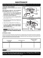
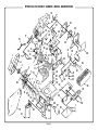
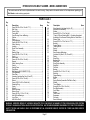
1
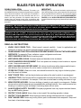
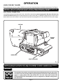
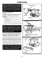
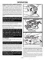
OWNER'S OPERATING MANUAL
3" DUSTLESS BELT SANDER / B850
DOUBLE INSULATED
SPECIFICATIONS:
Belt Size
Input
Overall Length
Net Weight
No Load Speed
75 mm x 534 mm (3" x 21")
230V, 3.9A, 850 Watt
314 mm (12-1/4")
4.2 Kg. (9.3 lbs.)
360 m/min.
THANK YOU FOR BUYING A RYOBI BELT SANDER.
Your new sander has been engineered and manufactured to Ryobi's high standard for dependability, ease of operation, and
operator safety. Properly cared for, it will give you years of rugged, trouble-free performance.
CAUTION: Carefully read through this entire owner's manual before using your new sander. Pay close attention to the
Rules for Safe Operation, Warnings, and Cautions. If you use your sander properly and only for what it is intended, you will
enjoy years of safe, reliable service.
Thank you again for buying Ryobi tools.
SAVE THIS MANUAL FOR FUTURE REFERENCE
RULES FOR SAFE OPERATION
DOUBLE INSULATION
IMPORTANT
Your Ryobi power tool is double insulated. This means you
are separated from the tool's electrical system by two complete
sets of electrical insulation. This extra layer of insulation is
intended to protect the user from electrical shock due to a
break in the wiring insulation. All exposed metal parts are
isolated from the internal metal motor components with
protecting insulation. Double insulated tools do not need to be
grounded.
Servicing of a tool with double insulation requires extreme
care and knowledge of the system and should be performed
only by a qualified service technician. For service we suggest
you return the tool to your nearest AUTHORIZED SERVICE
CENTER or other QUALIFIED SERVICE ORGANIZATION
for repair. When servicing use only identical Ryobi replacement
parts.
WARNING: THE DOUBLE INSULATED SYSTEM IS INTENDED TO PROTECT THE USER FROM SHOCK
RESULTING FROM A BREAK IN THE TOOL'S INTERNAL WIRING. OBSERVE ALL NORMAL SAFETY
PRECAUTIONS RELATED TO AVOIDING ELECTRICAL SHOCK.
WARNING: DO NOT ATTEMPT TO OPERATE THIS TOOL UNTIL YOU HAVE READ THOROUGHLY AND
UNDERSTAND COMPLETELY ALL INSTRUCTIONS, SAFETY RULES, ETC. CONTAINED IN THIS MANUAL.
FAILURE TO COMPLY CAN RESULT IN ACCIDENTS INVOLVING FIRE, ELECTRIC SHOCK, OR SERIOUS
PERSONAL INJURY. SAVE OWNER'S MANUAL AND REVIEW FREQUENTLY FOR CONTINUING SAFE
OPERATION AND INSTRUCTING OTHERS WHO MAY USE THIS TOOL.
READ ALL INSTRUCTIONS
1.
KNOW YOUR POWER TOOL - Read owner's manual carefully. Learn its applications and
limitations as well as the specific potential hazards related to this tool.
2.
GUARD AGAINST ELECTRICAL SHOCK BY PREVENTING BODY CONTACT WITH GROUNDED
SURFACES. For example: Pipes, radiators, ranges, refrigerator enclosures.
3.
KEEP GUARDS IN PLACE and in working order.
4.
KEEP WORK AREA CLEAN. Cluttered areas and benches invite accidents.
5.
AVOID DANGEROUS ENVIRONMENT. Don't use power tool in damp or wet locations or expose
to rain. Keep work area well lit.
6.
KEEP CHILDREN AND VISITORS AWAY. All visitors should wear safety glasses and be kept a
safe distance from work area. Do not let visitors contact tool or extension cord.
7.
STORE IDLE TOOLS. When not in use, tools should be stored in a dry, high or locked-up place out of the reach of children.
8.
DON'T FORCE TOOL. It will do the job better and safer at the rate for which it was designed.
9.
USE RIGHT TOOL. Don't force small tool or attachment to do the job of a heavy duty tool. Don't use
tool for purpose not intended - for example - Don't use a circular saw for cutting tree limbs or logs.
10. WEAR PROPER APPAREL. No loose clothing or jewelry to get caught in moving parts. Rubber
gloves and non-skid footwear are recommended when working outdoors. Also, wear protective hair
covering to contain long hair and keep it from being drawn into air vents.
11. ALWAYS WEAR SAFETY GLASSES. Everyday eyeglasses have only impact-resistant lenses;
they are NOT safety glasses.
12. PROTECT YOUR LUNGS. Wear a face or dust mask if the sanding operation is dusty.
13. PROTECT YOUR HEARING. Wear hearing protection during extended periods of operation.
14. DON'T ABUSE CORD. Never carry tool by cord or yank it to disconnect from receptacle. Keep cord
from heat, oil and sharp edges.
Page 2
RULES FOR SAFE OPERATION (Continued)
15. SECURE WORK. Use clamps or a vise to hold work. It's safer than using your hand and it frees both
hands to operate the tool.
16. DON'T OVERREACH. Keep proper footing and balance at all times. Do not use on a ladder or
unstable support.
17. MAINTAIN TOOLS WITH CARE. Keep tools sharp at all times, and clean for best and safest
performance. Follow instructions for lubricating and changing accessories.
18. DISCONNECT TOOLS. When not in use, before servicing, or when changing attachments, blades,
bits, cutters, sandpaper, etc., all tools should be disconnected from power supply.
19. REMOVE ADJUSTING KEYS AND WRENCHES. Form habit of checking to see that keys and
adjusting wrenches are removed from tool before turning it on.
20. AVOID ACCIDENTAL STARTING. Don't carry plugged-in tools with finger on switch. Be sure switch
is off when plugging in.
21. OUTDOOR USE EXTENSION CORDS. When tool is used outdoors, use only extension cords
suitable for use outdoors. Outdoor approved cords are marked with the suffix W-A, for example SJTW-A or SJOW-A.
22. NEVER USE THIS OR ANY POWER SANDER FOR WET SANDING OR LIQUID POLISHING.
Failure to comply can result in electrical shock causing serious injury or worse.
23. KEEP HANDS AWAY FROM SANDING AREA AND MOVING SANDING BELT.
24. NEVER USE IN AN EXPLOSIVE ATMOSPHERE. Normal sparking of the motor could ignite fumes.
25. INSPECT TOOL CORDS PERIODICALLY and if damaged, have repaired by an authorized service
center. Stay constantly aware of cord location.
26. INSPECT EXTENSION CORDS PERIODICALLY and replace if damaged.
27. KEEP HANDLES DRY, CLEAN, AND FREE FROM OIL AND GREASE. Always use a clean cloth
when cleaning. Never use brake fluids, gasoline, petroleum-based products or solvents to clean your
tool.
28. STAY ALERT. Watch what you are doing and use common sense. Do not operate tool when you
are tired. Do not rush.
29. CHECK DAMAGED PARTS. Before further use of the tool, a guard or other part that is damaged
should be carefully checked to determine that it will operate properly and perform its intended
function. Check for alignment of moving parts, binding of moving parts, breakage of parts, mounting,
and any other conditions that may affect its operation. A guard or other part that is damaged should
be properly repaired or replaced by an authorized service center.
30. DO NOT USE TOOL IF SWITCH DOES NOT TURN IT ON AND OFF. Have defective switches
replaced by an authorized service center.
31. Inspect for and remove all nails from lumber before sanding.
32. DRUGS, ALCOHOL, MEDICATION. Do not operate tool while under the influence of drugs, alcohol,
or any medication.
33. DO NOT USE THIS SANDER FOR OVERHEAD SANDER. Overhead sanding could result in
dropping sander or loss of control. These situations could result in an accident resulting in possible
serious injury.
34. When servicing use only identical Ryobi replacement parts.
35. SAVE THESE INSTRUCTIONS. Refer to them frequently and use them to instruct others who may
use this tool. If you loan someone this tool, loan them these instructions also.
Page 3
OPERATION
KNOW YOUR BELT SANDER
Before attempting to use your sander, familiarize yourself with all operating features and safety requirements. See Figure 1.
WARNING: IF ANY PARTS ARE MISSING DO NOT OPERATE YOUR SANDER UNTIL THE MISSING PARTS ARE
REPLACED. FAILURE TO DO SO COULD RESULT IN POSSIBLE SERIOUS PERSONAL INJURY.
ELECTRICAL CONNECTION
Your sander has a precision built electric motor. It should be connected to a power supply that is 230 volts, 50 Hz, AC only
(normal household current). Do not operate this tool on direct current (DC). A substantial voltage drop will cause a loss of
power and the motor will overheat. If your tool does not operate when plugged into an outlet, double-check the power supply.
DUST BAG
TRACKING
SCREW
SANDING BELT
FRONT IDLER PULLEY
Fig. 1
WARNING: DO NOT ALLOW FAMILIARITY WITH YOUR SANDER TO MAKE YOU CARELESS. REMEMBER
THAT A CARELESS FRACTION OF A SECOND IS SUFFICIENT TO INFLICT SEVERE INJURY.
WARNING:
The operation of any sander can result in foreign objects being thrown into your eyes, which
can result in severe eye damage. Before beginning power tool operation, always wear safety
goggles or safety glasses with side shields and a full face shield when needed. We
recommend Wide Vision Safety Mask for use over eyeglasses or standard safety glasses
with side shields.
Page 4
OPERATION
WARNING: YOUR SANDER SHOULD NEVER BE
CONNECTED TO POWER SUPPLY WHEN YOU
ARE ASSEMBLING PARTS, CHANGING BELTS,
OR MAKING ADJUSTMENTS.
LOCK "OFF" BUTTON
REAR HANDLE
SWITCH
The switch of your sander is equipped with a "lock-off" button
that reduces the possibility of accidental starting. You must
depress and hold the "lock-off" button, pull the switch trigger,
then release the "lock-off" button. See Figure 2.
WARNING: BEFORE CONNECTING YOUR
SANDER TO POWER SUPPLY SOURCE, ALWAYS
MAKE SURE YOU DO NOT HAVE THE SWITCH
TRIGGER DEPRESSED IN THE "ON" POSITION.
FAILURE TO DO SO COULD RESULT IN
ACCIDENTAL STARTING OF YOUR SANDER
RESULTING IN POSSIBLE SERIOUS INJURY.
APPLICATIONS
FRONT HANDLE
(Use only for the purpose listed below)
■
Coarse, medium and fine sanding of wood, metals,
plastics and other materials.
■
Smoothing rough boards, chamfering, rounding edges
and many other general sanding applications.
■
Removing rust, paint, varnishes, and stains.
Fig. 2
PREPARING FOR OPERATION
For ease of operation and maintaining proper control, your
sander has a front handle and a rear handle. These handles
allow two-hand operation which aid in maintaining control,
keeping sanding area level with workpiece, and keeping
hands clear of sanding belt. When operating your sander
always hold the front handle with your left hand and the rear
handle with your right hand as shown in Figure 2.
WARNING: KEEP HANDS AND FINGERS CLEAR
OF MOVING SANDING BELT, FRONT IDLER
PULLEY AND DRIVE ROLLER ASSEMBLY.
FAILURE TO DO SO WILL RESULT IN THE
SANDING OF YOUR HANDS OR FINGERS.
KEEP HANDS AND FINGERS
AWAY FROM THESE AREAS AT ALL TIMES
See Figure 3.
WARNING: DO NOT LET YOUR FINGERS REST
OVER THE FRONT OR RIGHT EDGE OF THE
SANDER. IF THE SANDING BELT WERE TO RUN
OFF, OR IF IT WERE NOT PROPERLY ADJUSTED,
YOUR FINGERS COULD COME IN CONTACT WITH
THE MOVING SANDING BELT RESULTING IN
POSSIBLE SERIOUS INJURY.
Always operate your sander as shown in Figure 2.
LUBRICATION
All of the bearings in this tool are lubricated with a sufficient
amount of high grade lubricant for the life of the unit under
normal operating conditions. Therefore, no further lubrication
is required.
Fig. 3
SANDING BELT SELECTION
Selecting the correct size and type sanding belt is an extremely
important step in achieving a high quality sanded finish.
Standard 75 mm x 534 mm sanding belts made of aluminum
oxide, silicon carbide, and other synthetic abrasives are best
for power sanding. In general, coarse grit will remove the
most material and fine grit will produce the smoothest finish
in all sanding operations. The condition of the surface to be
sanded will determine which grit belt will do the job. If the
surface is rough, start with a coarse grit and sand until the
surface is uniform. Medium grit may then be used to remove
scratches left by the coarser belt and fine grit belt used for
finishing of the surface. Always continue sanding with each
grit belt until surface is uniform.
Page 5
OPERATION
WARNING: ALWAYS WEAR SAFETY GOGGLES OR
SAFETY GLASSES WITH SIDE SHIELDS WHEN
OPERATING YOUR SANDER. IF THE SANDING
OPERATION IS DUSTY, ALSO WEAR A FACE OR
DUST MASK. FAILURE TO DO SO COULD RESULT IN
DUST OR LOOSE PARTICLES BEING THROWN INTO
YOUR EYES, RESULTING IN POSSIBLE SERIOUS
INJURY.
DUST BAG RETAINER
INSTALLING DUST BAG
See Figure 4.
DISCONNECT SANDER FROM POWER SUPPLY WHILE
ASSEMBLING PARTS OR MAKING ADJUSTMENTS.
TO INSTALL:
1. Fit opening in dust bag retainer over dust exhaust hole
on blower cover.
2. Slide dust bag retainer in the direction of the arrow as
shown in Figure 4.
3. Dust bag is secure when it fits snugly on blower cover.
4. For most efficient operation, empty dust bag when half
full.
DUST BAG
BLOWER COVER
Fig. 4
LOWER TENSION RELEASE LEVER TO SECURE
SANDING BELT
WARNING: TO PREVENT THE POSSIBILITY OF
SAWDUST BEING THROWN INTO YOUR FACE
AND EYES, NEVER ATTEMPT TO USE YOUR
SANDER WITHOUT DUST BAG PROPERLY
INSTALLED. SAWDUST BEING THROWN INTO
YOUR FACE AND EYES COULD RESULT IN
POSSIBLE SERIOUS INJURY.
INSTALLING AND ADJUSTING SANDING BELT
DISCONNECT SANDER FROM POWER SUPPLY WHILE
ASSEMBLING PARTS OR MAKING ADJUSTMENTS.
LIFT TENSION RELEASE LEVER TO REMOVE
SANDING BELT
Fig. 5
To release the sanding belt, lift tension release lever straight
up as shown in figure 5. When sufficient force is exerted, the
spring will be compressed allowing the pulley to lock in a rear
position. This frees the sanding belt so it can be removed.
Install new belt. See Figure 6. Roughly align the belt to its
correct position, then release tension on pulley. Release
tension by lowering tension release lever as shown in Figure
5. The pulley will snap back into operating position.
WARNING: KEEP HANDS AND FINGERS CLEAR
OF FRONT IDLER PULLEY AND SPRING
MECHANISM AT ALL TIMES. FAILURE TO DO SO
COULD RESULT IN THEM GETTING PINCHED,
RESULTING IN POSSIBLE SERIOUS INJURY..
SANDING BELT
Page 6
Fig. 6
OPERATION
ALWAYS WEAR SAFETY GOGGLES OR SAFETY
GLASSES WITH SIDE SHIELDS WHEN OPERATING YOUR
SANDER. To adjust sanding belt, connect sander to power
supply. Place sander in upside down position as shown in
Figure 7. NOTE: This position is for adjustments only. The
sander is not in an operating position. Pull switch trigger and
release immediately. Observe tracking of sanding belt. If the
sanding belt runs inward, turn the tracking screw clockwise.
If the sanding belt runs outward, turn the tracking screw
counterclockwise. This should be done until you are sure belt
will not run off sander, or come in contact with internal parts.
After installing a new sanding belt, it may become necessary
to change the adjustment several times until the belt becomes
pliable.
SANDING BELT
WARNING: IF SANDING BELT BEGINS TO WEAR
EXCESSIVELY ON THE INNER EDGE, READJUST
TRACKING SCREW. IT IS ADJUSTED TOO FAR
INWARD AND THE SANDING BELT IS RUBBING
AGAINST INTERNAL PARTS.
Fig. 7
TRACKING SCREW
When you are sure the belt will not rub against internal
parts, start your sander and fine adjust the tracking
screw until the belt stablizes. See Figure 8.
When correctly adjusted, the outer edge of the belt will
be even with the outer edge of the base of your sander.
Belt life will be greatly increased if a few seconds are
spent adjusting the belt tracking.
WARNING: KEEP HANDS AND FINGERS AWAY
FROM MOVING SANDING BELT. ANY PART OF
YOUR BODY COMING IN CONTACT WITH MOVING
BELT COULD RESULT IN SERIOUS INJURY. DO
NOT WEAR LOOSE CLOTHING OR JEWELRY
WHEN OPERATING YOUR SANDER. THEY COULD
GET CAUGHT IN MOVING PARTS AND FOREIGN
OBJECTS COULD GET THROWN AWAY FROM
SANDER CAUSING INJURY.
TURN TRACKING SCREW
TO ADJUST SANDING BELT
Fig. 8
TO OPERATE
Clamp or otherwise secure the work to prevent it from
moving under your sander.
WARNING: UNSECURED WORK COULD BE THROWN
BACK TOWARD OPERATOR CAUSING INJURY.
Before placing sander on work surface, squeeze the trigger
switch and let the motor reach its maximum speed, then
lower your sander to the work surface with a slight forward
motion. Using the rear handle to control your sander and the
front handle only to guide it, move it slowly over the work. See
Figure 9. Allowing your sander to remain in one place will
result in an uneven surface.
WARNING: KEEP A FIRM GRIP ON SANDER WITH
BOTH HANDS AT ALL TIMES. FAILURE TO DO SO
COULD RESULT IN LOSS OF CONTROL LEADING TO
POSSIBLE SERIOUS INJURY.
Fig. 9
Your sander was designed to provide the proper weight on
the sanding belt. Extra pressure will result in uneven work,
clogged belts, and possible motor burnout. NOTE: The front
roller of your sander was not designed for contour sanding.
Sanding on the front roller could cause irregularity in sanding
belt tracking.
Use a coarser belt when heavy cutting is desired, not heavy
pressure. The importance of this cannot be over-emphasized.
The weight has been built into the tool to give the most
efficient pressure at the proper location.
Page 7
MAINTENANCE
WARNING: WHEN SERVICING USE ONLY IDENTICAL RYOBI REPLACEMENT PARTS. USE OF ANY OTHER
PARTS MAY CREATE A HAZARD OR CAUSE PRODUCT DAMAGE.
TIMING BELT REPLACEMENT
SMALL
PULLEY
DISCONNECT SANDER FROM POWER SUPPLY BEFORE
SERVICING.
WHEN REPLACING TIMING BELT USE RECOMMENDED
REPLACEMENT BELT ONLY. See Parts List, Page 11.
1. Remove sanding belt from sander. See installing and
adjusting sanding belt, Page 6. NOTE: REMOVING THE
SANDING BELT WILL SIMPLIFY THE PROCESS OF
INSTALLING YOUR NEW TIMING BELT.
LARGE
PULLEY
2. Remove the two belt cover screws. Then remove the belt
cover. See Key Numbers 1 and 2 on exploded view and
parts list, pages 10 and 11.
BELT COVER
BELT
COVER SCREWS
Fig. 10
APPLY PRESSURE
HERE AND TURN LARGE PULLEY
3. Force old belt from small pulley with a screwdriver and
remove it from large pulley. If it is worn out, simply cut the
old belt and remove it.
4. Install new belt over large pulley first. See Figure 10.
5. Holding the belt as shown in Figure 11, press the belt onto
the small pulley. NOTE: TO SIMPLIFY THE PROCESS,
TURN THE LARGE PULLEY AS YOU PRESS THE BELT
ONTO THE SMALL PULLEY.
6. Reassemble belt cover and screws.
CAUTION: NEVER ATTEMPT TO OPERATE YOUR
SANDER WITHOUT BELT COVER IN PLACE. FAILURE
TO DO SO COULD RESULT IN POSSIBLE SERIOUS
INJURY.
Fig. 11
EXTENSION CORDS
The use of any extension cord will cause some loss of power. To keep the loss to a minium and to prevent tool from overheating,
follow the recommended cord sizes on the table. Every 230 volt flexible extension cord shall be of heavy duty sheathed type
to comply with AS3199, Approval and Test Specification, Cord Extension Sets. When working with your tool outdoors, use an
extension cord suitable for outdoor use and so marked.
Cord extension
set rating
Conductor area sq.
mm
Maximum length of
flexible cord
m
10
10
15
15
20
20
1.0
1.5
1.5
2.5
2.5
4.0
25
32
25
40
32
40
CAUTION: Keep extension cords away from the sanding area and position the cord so that it will not get caught on lumber,
tools, etc., during sanding.
WARNING: CHECK EXTENSION CORDS BEFORE EACH USE. IF DAMAGED REPLACE IMMEDIATELY.
NEVER USE TOOL WITH A DAMAGED CORD SINCE TOUCHING THE DAMAGED AREA COULD CAUSE
ELECTRICAL SHOCK RESULTING IN SERIOUS INJURY.
Page 8
MAINTENANCE
SCREWS
SMALL DIAMETER
NAIL OR PIN
CORD CLAMP
CONNECTOR
BEND RELIEF
POWER CORD
BLACK
BROWN
YELLOW
SCREW
SCREWS
SUPPRESSOR
SCREWS
SWITCH
CLEAR (GROUND)
WHITE
SCREW
SWITCH
LIGHT BLUE
HANDLE COVER
SUPPRESSOR
Fig. 12
SWITCH REPLACEMENT
CORD REPLACEMENT
DISCONNECT THE SANDER FROM POWER SUPPLY WHILE
REPLACING PARTS OR MAKING ADJUSTMENTS.
1. Remove the handle cover and screws. NOTE THE
LOCATIONS OF ALL WIRING IN THE HANDLE AND
HOW EACH CONNECTION IS MADE TO THE SWITCH.
Connections and wiring position must be identical when
installing the new switch. See Figure 12.
2. Lift the switch away from the handle. Release power cord
leads from the switch by loosening the two screws in the
switch body.
3. Release motor leads from switch by inserting a small
diameter pin or nail into remaining switch lead receptacles.
See Figure 12.
4. Make lead connections to the new switch by positioning
power cord leads in place and tightening the two screws
on switch body. Push motor leads as far as possible into
the switch lead receptacles. Pull on leads to check lead
connections with lead receptacles.
5. Position the switch in place, and arrange the wiring in the
handle so that it will not be pinched or contact screws
when the handle cover and screws are replaced. See
Figure 12.
6. Arrange suppressor, connectors, and suppressor leads
in the handle so that they will not be pinched or contact
screws when the handle cover and screws are replaced.
See Figure 12.
7. Replace handle cover and screws.
8. Tighten all screws securely.
DISCONNECT THE SANDER FROM POWER SUPPLY
WHILE REPLACING PARTS OR MAKING ADJUSTMENTS.
1. Remove handle cover and screws. NOTE THE
LOCATIONS OF ALL WIRING IN THE HANDLE AND
HOW EACH CONNECTION IS MADE TO THE CORD.
Connections and wiring position must be identical when
installing the new cord. See Figure 12.
2. Remove the cord clamp screws and cord clamp.
3. Lift the switch away from the handle. Release power cord
leads from the switch by loosening the two screws in the
switch body.
4. Remove the bend relief from the old cord and place it on
the new one.
5. Make new power cord lead connections to switch by
positioning leads in place and tightening the two screws on
the switch body. Pull on leads to check lead connections
with lead receptacles.
6. Position the switch in place, and arrange all wiring in the
handle so that it will not be pinched or contact screws when
the handle cover and screws are replaced. See Figure 12.
7. Arrange suppressor, connectors, and suppressor leads in
the handle so that they will not be pinched or contact
screws when the handle cover and screws are replaced.
See Figure 12.
8. Replace cord clamp, cord clamp screws, handle cover,
and handle cover screws.
9. Tighten all screws securely.
GENERAL
Avoid using solvents when cleaning plastic parts. Most
WARNING: DO NOT AT ANY TIME LET BRAKE
plastics are susceptible to various types of commercial
FLUIDS, GASOLINE, PETROLEUM-BASED
solvents and may be damaged by their use. Use clean cloths
PRODUCTS, PENETRATING OILS, ETC., COME
to remove dirt, carbon dust, etc.
IN CONTACT WITH PLASTIC PARTS. THEY
When electric tools are used on fiberglass boats, sports cars,
CONTAIN CHEMICALS THAT CAN DAMAGE,
wallboard, spackling compounds, or plaster, it has been
WEAKEN, OR DESTROY PLASTIC.
found that they are subject to accelerated wear and possible
premature failure, as the fiberglass chips and grindings are
WARNING: ALWAYS WEAR SAFETY GOGGLES
highly abrasive to bearings, brushes, commutator, etc.
OR SAFETY GLASSES WITH SIDE SHIELDS
Consequently it is not recommended that this tool be used
DURING POWER TOOL OPERATION OR WHEN
for extended work on any fiberglass material, wallboard,
BLOWING DUST. IF OPERATION IS DUSTY ALSO
spackling compounds, or plaster. During any use on these
WEAR A DUST MASK.
materials, it is extremely important that the tool is cleaned
frequently by blowing with an air jet.
Page 9
RYOBI DUSTLESS BELT SANDER - MODEL NUMBER B850
74
20
34
21
19
17
73
16
15
14
13
1
71
22
15
23
33
12 75
25 26
24
12
31
28 29
27 15
18
72
4
69
49
50
51
52
6 8 9
38
39
11
6 7
47
48
47
40
41
42
43
53
44
45
54
55
65
64
63
62
70
36 37
24
5 10
68
31 67
66
32
30
14
2
3
35
28
58
28
60 59
61
61
Page 10
57
56
1
46
RYOBI DUSTLESS BELT SANDER - MODEL NUMBER B850
The model number will be found on a plate attached to the motor housing. Always mention the model number in all correspondence regarding your
Belt Sander or when ordering repair parts.
PARTS LIST
Key
No.
1
2
3
4
5
6
7
8
9
10
11
12
13
14
15
16
17
18
19
20
21
22
23
24
25
26
27
28
29
30
31
32
33
34
35
36
37
38
39
Description
Quan.
Screw (#8-32 x 3/8 in. Pan Hd. T. F.) .................................. 4
Belt Cover ............................................................................ 1
Driven Pulley ........................................................................ 1
Timing Belt ........................................................................... 1
Gear Housing Cover w/Bearing ........................................... 1
Washer ................................................................................. 2
Pinion ................................................................................... 1
Flange Bearing ..................................................................... 1
Screw (#8-32 x 7/8 in. Fil. Hd.) ............................................ 1
Motor Housing ...................................................................... 1
Insulator ............................................................................... 2
Brush Tube Assembly .......................................................... 2
Pulley ................................................................................... 1
Bearing Strap ....................................................................... 2
Screw (#8-10 x 1/2 in. Fil. Hd.) ............................................ 6
Cord ..................................................................................... 1
Bend Relief .......................................................................... 1
Screw (#6-19 x 5/8 in. Pan Hd.) .......................................... 2
Bumper ................................................................................. 2
Motor Housing Cover ........................................................... 1
Switch ................................................................................... 1
Handle Cover ....................................................................... 1
Field Strap ............................................................................ 1
Ball Bearing (NACHI 608ZZ C3/1E) .................................... 2
Field Assembly ..................................................................... 1
Data Plate ............................................................................ 1
Armature (Includes Key Nos. 24 and 72) ............................ 1
Screw (#8-10 x 5/8 in. Pan Hd.) .......................................... 7
Blower .................................................................................. 1
Screw (#10-32 x 3/8 in. Wafer Hd.) ..................................... 1
Retaining Ring ..................................................................... 2
Spring ................................................................................... 1
Shroud .................................................................................. 1
Blower Housing .................................................................... 1
Blower Cover ....................................................................... 1
Screw (#8-10 x 1-1/8 in. Fil. Hd.) ......................................... 3
Idler Roller w/Bearings ......................................................... 1
Logo Plate ............................................................................ 1
Idler Roller Shaft .................................................................. 1
Key
No.
40
41
42
43
44
45
46
47
48
49
50
51
52
53
54
55
56
57
58
59
60
61
62
63
64
65
66
67
68
69
70
71
72
73
74
75
Description
Quan.
Yoke Assembly (Includes Key No. 32) ................................ 1
Release Lever Assembly ..................................................... 1
Washer ................................................................................. 1
Screw (#10-32 x 1/2 in. Pan Hd.) ........................................ 1
75 mm x 534 mm Sanding Belt — Complete Assortment
Available at Your Nearest Catalog Order or Retail Store .... 1
Glamor Plate ........................................................................ 1
Screw (#10-32 x 7/8 in. Pan Hd. T. F.) ................................ 2
Bushing ................................................................................ 2
Torsion Spring ...................................................................... 1
Tracking Knob ...................................................................... 1
Spring ................................................................................... 1
Washer ................................................................................. 1
Gear Housing w/Bearings
(Includes. Key Nos. 8, 59, 60 and 63) ................................. 1
Platen ................................................................................... 1
Wear Strip ............................................................................ 1
Backing Pad ......................................................................... 1
Wear Plate ........................................................................... 1
Drive Roller Assembly ......................................................... 1
Steel Ball .............................................................................. 1
Felt Seal ............................................................................... 1
Bearing ................................................................................. 1
Screw (#8-10 x 2-1/4 in. Fil. Hd.) ......................................... 4
Deflector ............................................................................... 1
Flange Bearing ..................................................................... 1
Washer ................................................................................. 1
Gear ..................................................................................... 1
Spring Washer (Assemble Flat Side to Gear) ..................... 1
Washer ................................................................................. 1
Thrust Washer ..................................................................... 1
Screw (#8-32 x 3/8 in. Pan Hd.) .......................................... 3
Dust Bag Assembly .............................................................. 1
Cord Clamp .......................................................................... 1
Washer ................................................................................. 1
Yellow Lead ......................................................................... 1
Suppressor ........................................................................... 1
Connector ............................................................................ 1
Owner’s Manual
WARNING: IMPROPER REPAIR OF A DOUBLE INSULATED TOOL CAN RESULT IN DAMAGES TO THE DOUBLE INSULATION SYSTEM
POSSIBLY CAUSING ELECTRICAL SHOCK OR ELECTROCUTION. ANY REPAIRS REQUIRING DISASSEMBLY OF YOUR TOOL REQUIRES
SAFETY TESTING AND SHOULD ONLY BE PERFORMED BY AN AUTHORIZED SERVICE CENTER OR OTHER QUALIFIED SERVICE
ORGANIZATION.
Page 11
OWNER'S OPERATING MANUAL
3" DUSTLESS BELT SANDER / B850
DOUBLE INSULATED
• SERVICE
Now that you have purchased your Tool, should a need ever exist for repair parts or service,
simply contact your nearest Ryobi Authorized Service Center or other qualified service
organization. Be sure to provide all pertinent facts when you call or visit.
• MODEL NO.
The model number of your Tool will be found on a plate attached to the motor housing.
• HOW TO ORDER REPAIR PARTS
WHEN ORDERING REPAIR PARTS,
ALWAYS GIVE THE FOLLOWING INFORMATION:
•
MODEL NUMBER
B850
•
PART DESCRIPTION
•
NAME OF ITEM
3" Dustless Belt Sander
All parts listed may be ordered from any Ryobi Authorized Service Center or other qualified
service organization.
972000-483
11-97
Printed in U.S.A.