1
TM
WMG -Administrator!
Messaging Switch
Series: Wireless Messaging System
System Version: Two-Way 3.0,
One-Way 1.07
Software Version: 3.3.7
Software Installation
Issue Date: April 1998
6880493G51-A
TM
WMG -Administrator!
Messaging Switch
Series: Wireless Messaging System
System Version: Two-Way 3.0,
One-Way 1.07
Software Version: 3.3.7
Software Installation
Issue Date: April 1998
6880493G51-A
WMG-Administrator! Messaging Switch Software Installation
Foreword
General Information
The information in this manual has been reviewed for accuracy. However, no responsibility is
assumed for inaccuracies. Motorola reserves the right to make changes to any products
discussed herein. The information in this document is subject to change without notice.
Motorola assumes no liability for hardware or software damage or loss of data because of
errors or omissions in this manual. Motorola does not assume any liability arising from the
application or use of any products or circuits described herein. Neither does Motorola convey
any license under its patents or right of others.
Refer questions concerning the contents of this manual or requests for related circuit board
information to the following location:
Motorola, Inc.
Paging Systems Group
Multimedia Publications Department
5401 North Beach St., MS E230-A
Fort Worth, TX 76137-2794
or telephone:
(817) 245-2824
To access on-line electronic information (BBS) for service notices and the latest software
releases, call the Paging One-Call-Support Center. To request additional manuals or parts,
please contact the Motorola Americas Parts Division:
telephone:
facsimile:
(800) 422-4210
(847) 538-8198
To request a part number, contact the Parts Identification Group:
telephone:
(847) 538-0021
For Motorola Infrastructure and communicator test equipment, contact the Motorola Test
Equipment Center:
telephone:
03/23/98
April 1998
(800) 505-8378
6880493G51-A
iii
Foreword
WMG-Administrator! Messaging Switch Software Installation
Global Service Organization
Motorola provides Infrastructure and communicator technical support through authorized or
company-owned Service Centers. Motorola also provides service for communicators on a
contract basis. For contract service information, please contact your local Motorola
representative or the Paging One-Call-Support Center:
Motorola, Inc.
Paging One-Call-Support Center
5401 North Beach St., MS E112
Fort Worth, TX 76137-2794
telephone:
facsimile:
(800) 520-7243 or
(817) 245-4663
(817) 245-2141
Service Training
Motorola, through its Advanced Messaging Technical Training Group in Fort Worth, Texas,
offers courses on communicators, messaging switches, transmitters, and receivers. These
courses are taught on the site or at a customer’s location.
Students learn to install, configure, and maintain Motorola messaging systems. The
classrooms at Motorola are equipped to ensure hands-on experience in practical lab exercises.
Training courses range from a basic introduction to communicators and messaging systems to
customized classes on specific systems and large system applications.
To obtain a course catalog or scheduling information, please call (817) 245-2184 or (800) 7243588 and ask for the training coordinator.
Computer Software Copyrights
The Motorola products described in this manual might include copyrighted Motorola
computer software stored in semiconductor memories and other media. Laws in the United
States and other countries preserve for Motorola certain exclusive rights for copyrighted
computer programs, including the exclusive right to copy or reproduce in any form the
copyrighted computer software.
Accordingly, any copyrighted Motorola computer software contained in the Motorola
products described in this manual cannot be copied or reproduced in any manner without the
express written permission of Motorola.
iv
6880493G51-A
April 1998
WMG-Administrator! Messaging Switch Software Installation
Foreword
Furthermore, the purchase of Motorola products does not grant, either directly or by
implication, estoppel, or otherwise, any license under the copyrights, patents or patent
applications of Motorola, except for the normal, nonexclusive, royalty-free license to use that
arises by operation of law in the sale of a product.
Trademarks
Motorola and FLEX are trademarks of Motorola, Inc. Other trademarks are noted as such
throughout this document.
Antares and Dialogic are trademarks of Dialogic Corporation. HP and LaserJet are registered
trademarks of Hewlett-Packard Company. Intel is a registered trademark, and 80286 and
Pentium are trademarks of Intel Corporation. UnixWare is a registered trademark of Novell,
Inc. Solaris is a registered trademark of Sun Microsystems, Inc. Static Stop is a registered
trademark of Barco Chemical Products. Informix is a registered trademark of Informix
Software, Inc.
Trademarks contained herein are the acknowledged property of their respective owners.
Important Safety Information
The installation, maintenance, and/or operation of this equipment may present potentially
unsafe conditions, including, but not limited to, electrical shock, improper voltage to
components, and improper operation that can cause personal injury, death or damage to
property.
Read Instructions: Read all the safety instructions before operating the equipment. Retain
these safety instructions for future reference. Specialized procedures and instructions are
required and must be followed. Also, all applicable safety procedures, such as Occupational,
Safety, and Health Administration (OSHA) requirements, National Electric Code
Requirements, local code requirements, safe working practices, and good judgement must be
used by personnel.
April 1998
6880493G51-A
v
Foreword
WMG-Administrator! Messaging Switch Software Installation
Heed Admonitions: Adhere to all warnings on the equipment and in the operating
instructions. Follow all operating and use instructions. Two safety admonitions are used in
this instruction manual to indicate:
•
Equipment damage–
This safety admonition applies to an operating or maintenance procedure, practice or
condition which, if not strictly observed, could result in damage to the equipment or
database.
•
Personal injury or injury that may result in death–
This safety admonition applies to an operating or maintenance
procedure, practice or condition which, if not strictly observed, could
result in serious personal injury or death.
Mounting: Mount the equipment only as recommended by the manufacturer. Situate the
equipment away from heat sources such as radiators, heat registers, stoves, or other
equipment (including amplifiers) that produces heat.
Power Sources and Grounding: Connect the equipment to the type of power source
described in the installation instructions or as marked on the equipment. Take precautions to
avoid defeating the grounding or polarization provisions of the equipment. Disconnect the
power to the equipment by a circuit breaker when left unused for long periods of time.
Cleaning: Clean the outside of the equipment by using only a damp cloth. Do not immerse the
equipment in any type of liquid, including water. Do not use liquid cleaners or aerosol
cleaners. Dirt or other foreign matter should not be allowed to accumulate in the interior of
the enclosure.
Damage Requiring Service: Do not attempt to perform service functions that are not
described in the operating instructions. All other servicing should be referred to qualified
service personnel.
vi
6880493G51-A
April 1998
WMG-Administrator! Messaging Switch Software Installation
Foreword
Telephone Line Installation: All telephone line connections to the equipment should be
accomplished with the telephone lines disconnected from the network interface.
Motorola is not responsible for static damage to equipment not sold under the Motorola logo.
Motorola, Inc. 1999. All rights reserved. Printed in the U.S.A.
April 1998
6880493G51-A
vii
Foreword
viii
WMG-Administrator! Messaging Switch Software Installation
6880493G51-A
April 1998
PSG Limited Equipment Warranty for
Non-U.S. and Non-Canadian Markets
General Terms
1.
Motorola Paging Systems Group (PSG) manufactured infrastructure equipment is
warranted to be free from defects in material and workmanship to the original purchaser
only as set forth herein.
2.
This Warranty covers only that equipment identified in paragraph 1 that is used in the
manner and for the purpose intended.
3.
This Warranty specifically excludes any and all software products from any source. PSG
software products are the subject of the PSG Software Maintenance Program, addressed
separately.
4.
This Warranty shall commence 30 days after the date of shipment of the PSG
infrastructure equipment.
5.
The term of Warranty for all PSG infrastructure equipment is one (1) year parts and
labor.
Limitations And Qualifications of Warranty
6.
LIMITATION—THE REMEDY UNDER THIS WARRANTY IS LIMITED TO
MOTOROLA'S REPAIR OR REPLACEMENT OF DEFECTIVE EQUIPMENT. THIS
WARRANTY IS IN LIEU OF ALL OTHER WARRANTIES OR CONDITIONS,
EXPRESSED OR IMPLIED, INCLUDING, BUT NOT LIMITED TO, THE IMPLIED
WARRANTIES OF MERCHANTABILITY AND FITNESS FOR A PARTICULAR
PURPOSE.
7.
This Warranty does not cover, nor include a remedy for, damages, defects or failure
caused by:
a.
08/01/97
Revised July 1997
The equipment or any part of it NOT having been installed, modified, adapted,
repaired, maintained, transported or relocated in accordance with Motorola
technical specifications and instructions;
ix
Warranty
b.
Storage not conforming to the Shipping, Receiving, and Installation section of the
applicable Motorola Equipment Manual;
c.
Environmental characteristics not conforming to the applicable Motorola
Equipment Manual;
d.
Nonconformance with the Equipment Operating Instructions in the applicable
Motorola Equipment Manual;
e.
External causes including, without limitation, use in conjunction with incompatible
equipment, unless such use was with or under Motorola's prior written consent;
f.
Cosmetic damages;
g.
Damages caused by external electrical stress;
h.
Lightning;
i.
Accidental damage;
j.
Negligence, neglect, mishandling, abuse, or misuse;
k.
Force Majeure; and
l.
Damage caused by Shipper(s).
Return of Equipment
8.
x
If an item of PSG infrastructure equipment malfunctions or fails in normal use within the
Warranty Period:
a.
The Customer shall promptly notify the nearest Motorola Area Customer Care
Center (CCC) of the problem and provide the serial number of the defective item.
Motorola shall then, at its option, either resolve the problem over the telephone or
issue a Return Authorization Number to the Customer. The Customer shall, at its
cost, ship the item to the Motorola Area CCC location designated at the time the
Return Authorization Number is issued;
b.
The Return Authorization Number must be shown on the label attached to each
returned item. A description of the fault must accompany each returned item. The
returned item must be properly packed, and the insurance and shipping charges
prepaid;
c.
Motorola shall either repair or replace the returned item. The replacement item may
be new or refurbished. When refurbished, it shall be equivalent to new in operation.
When a returned item is replaced by Motorola, the returned item shall become the
property of Motorola;
Revised July 1997
Warranty
d.
Subject to all the terms of this Warranty, part availability and the clearance of
Customs, Motorola shall complete the repair or exchange of Motorola-manufactured
equipment returned under Warranty within fifteen (15) working days of receipt of
the equipment;
e.
Motorola shall, at its cost, ship the repaired or replaced item to the Customer. If the
Customer has requested Express Shipping, the Customer shall pay Motorola an
expedite fee; and
f.
Equipment which is repaired or replaced by Motorola shall be free of defects in
material and workmanship for the remainder of the original Warranty, or for 90 days
from the date of repair or replacement, whichever is longer. All other terms of this
Warranty shall apply to such repairs or replacements.
Advance Replacements
9.
During the Warranty Period:
a.
At the Customer's request and for the Customer's convenience, Motorola may
supply the Customer with Advance Replacement Parts (parts furnished in advance
of Motorola's receipt of defective items). Motorola's provision of such parts will be
contingent on part availability and on the Customer's maintaining a satisfactory
credit standing with Motorola.
b.
Motorola shall ship the Advance Replacement Parts requested by the Customer
within 48 hours of Motorola determining that such service is appropriate, if stock is
available at the Motorola service location. If stock is not available, Motorola will
make reasonable efforts to locate and provide it to the Customer within ten (10)
working days.
c.
The Customer shall return defective items to the Motorola Area Customer Care
Center within thirty (30) days from the date of shipment of the Advance
Replacement Parts; failing which, Motorola shall bill and the Customer shall pay the
full current list price of the Advance Replacement Parts.
10. To secure payment of the list price of Advance Replacement Parts if the defective items
are not returned to Motorola, the Customer hereby grants to Motorola a purchase money
security interest in any Advance Replacement Parts.
Revised July 1997
xi
Warranty
Excluded Equipment
11. The following equipment is excluded from this Warranty and is covered instead by the
Original Equipment Manufacturer's Warranty:
a.
Equipment which is not an integral part of a basic system configuration and which
is not manufactured by Motorola, such as batteries and satellite dish LNBs;
b.
Peripheral equipment such as printers, modems, data loggers, video display
terminals, and lightning and surge protectors; and
c.
Equipment which is not listed in Motorola's Price Book.
Force Majeure
12. Motorola shall not be responsible for failure to discharge its obligations under this
Warranty due to delays by suppliers, material shortages; strikes, lockouts or other labor
disputes; disturbances, government regulations, floods, lightning, fires, wars, accidents,
acts of God, and any other causes beyond Motorola's reasonable control.
Default and Termination
13. Motorola shall have the right to immediately terminate this Warranty, and to suspend its
performance under this Warranty, upon notification to the Customer if the Customer:
a.
Assigns or transfers the Customer's rights or obligations under this Warranty
without the prior written consent of Motorola; or
b.
Within thirty (30) days of written demand by Motorola, fails to pay (1) any charge
for Advance Replacement Parts supplied under this Warranty, if the Customer has
not timely returned the defective items, or (2) any other amount that may be due.
14. Notwithstanding any such termination of the Warranty to the Customer, the Customer
shall remain responsible for all amounts then due.
Limitation of Liability
15. IN NO EVENT SHALL MOTOROLA BE LIABLE FOR ANY INDIRECT, INCIDENTAL,
SPECIAL OR CONSEQUENTIAL DAMAGES ARISING OUT OF THIS WARRANTY,
EVEN IF MOTOROLA HAS BEEN ADVISED OF THE POSSIBILITY THEREOF,
INCLUDING, WITHOUT LIMITATION, LOST PROFITS AND REVENUES, FAILURE
TO REALIZE EXPECTED SAVINGS, LOST DATA OR ANY CLAIMS AGAINST THE
CUSTOMER BY A THIRD PARTY.
xii
Revised July 1997
WMG-Administrator! Messaging Switch Software Installation
Contents
Introduction,
1-1
About This Manual,
WMG MS Overview,
1-2
1-5
Installing WMG System Software,
2-1
WMG MS Software Installation Overview,
2-3
System Software Installation—Required Materials,
Configuring the X-Terminal,
2-4
2-6
Installing the OMC Operating System and Database,
Configuring the Terminal Server,
2-25
Configuring the Ethernet Switch,
2-37
Configuring File Server Software,
2-43
Local Printer Setup,
2-48
Installing the WMG CP Operating System,
Loading WMG Applications,
Installing the UCC Software,
2-56
2-69
3-1
UCC Software Installation Overview,
Required Tools and Equipment,
Running the WinBIOS Setup,
3-2
3-3
3-5
Configuring the Ethernet Boards,
Installing UnixWare 2.1 or 2.1.2,
3-11
3-15
Installing UnixWare 2.1.1 OS Upgrade,
3-23
Installing UnixWare 2.1.2 OS Upgrade,
3-26
Installing E1 or T1 Dialogic Software,
April 1998
2-12
3-29
Installing the Global Call Development Package,
3-34
Installing the R2 Protocol Disk (E1 Option Only),
3-36
6880493G51-A
xiii
Contents
WMG-Administrator! Messaging Switch Software Installation
Loading Dialogic Patches,
3-37
Loading the UCC System Installation Script,
Configuring the UCC System,
Generating the Clone Tape,
3-40
3-42
Restoring the UCC System Cloning Tape,
Wireless Messaging System Terminology,
IP Addresses and Network Diagram,
xiv
3-38
3-45
A-1
B-1
6880493G51-A
April 1998
WMG-Administrator! Messaging Switch Software Installation
Figures
Figure 1-1:
Figure 1-2:
Figure 1-3:
Figure 2-1:
Figure 2-2:
Figure 2-3:
Figure 2-4:
Figure 2-5:
Figure 2-6:
Figure 2-7:
Figure 2-8:
Figure 2-9:
Figure 2-10:
Figure 2-11:
Figure 2-12:
Figure 2-13:
Figure 2-14:
Figure 2-15:
Figure 2-16:
Figure 2-17:
Figure 2-18:
Figure 2-19:
Figure 2-20:
Figure 2-21:
Figure 2-22:
Figure 2-23:
Figure 2-24:
Figure 2-25:
April 1998
The WMG-Administrator! MS and the Wireless Messaging System, 1-6
WMG MS—Typical Redundant DC Powered Two-Cabinet Configuration
Without SS7, 1-8
WMG MS—Typical DC-Powered Third Cabinet Configuration with Four
UCCs, 1-9
Boot Monitor Main Menu, 2-7
Connecting the NCD X-Terminal to the OMC TTYA/B Port—Themis
Systems, 2-9
Connecting the NCD X-terminal to the OMC console Port—Ultra-Based
Systems, 2-10
NCD User Services Console Window, 2-11
Openboot Parameters for OMC, 2-14
Terminal Selection, 2-16
Install Solaris Software—Initial, 2-19
Exit Solaris Installation Window, 2-20
Information Installation Script Menu, 2-22
Root Password Window, 2-23
Terminal Server Connections, 2-27
Administration Menu, 2-28
Server Configuration Window for Version 3.5.02, 2-29
Server Configuration Window for Version 4.00.19, 2-30
Administration Menu, 2-32
Administration Menu, 2-34
Server Configuration window, 2-35
IP Level Parameters, 2-40
File Server Setup Menu, 2-44
File Server Configuration, 2-47
Connecting the X-Terminal to the Themis CP1 or CP2 TTA/B Port, 2-56
Connecting the X-Terminal to the Ultra Primary or Secondary CP, 2-57
NCD User Services Console Window, 2-58
Select Type of Terminal, 2-61
Solaris Installation Program Window, 2-62
6880493G51-A
xv
Figures
WMG-Administrator! Messaging Switch Software Installation
Figure 2-26:
Figure 2-27:
Figure 2-28:
Figure 2-29:
Figure 2-30:
Figure B-1:
xvi
Install Solaris Software, 2-64
Exit Solaris Installation Window, 2-65
Root Password Window, 2-67
UCC Application Installation Window, 2-72
UCC File Extraction Window, 2-74
Themis Based Systems Network Diagram, B-3
6880493G51-A
April 1998
WMG-Administrator! Messaging Switch Software Installation
Tables
Table 1-1:
Table 2-1:
Table 3-1:
Table 3-2:
Table 3-3:
Table 3-4:
Table 3-5:
Table 3-6:
Table 3-7:
Table 3-8:
Table A-1:
Table A-2:
Table B-1:
April 1998
Conventions Used in This Manual, 1-4
Terminal Server Navigation Keys, 2-25
Using WinBIOS Navigation Keys , 3-5
Advanced Setup Window Settings (Sheet 1 of 2), 3-6
Chipset Setup Window Settings , 3-8
Chipset Setup Window Settings , 3-9
Peripheral Setup Window Settings, 3-10
Using EZStart Navigation Keys , 3-11
Ethernet Board Settings, 3-14
Using UnixWare Navigation Keys, 3-15
The Wireless Messaging System Glossary List (Sheet 1 of 6),
Telecommunications Terminology (Sheet 1 of 6), A-6
WMG MS Address Assignments (Sheet 1 of 2), B-1
6880493G51-A
A-1
xvii
Tables
xviii
WMG-Administrator! Messaging Switch Software Installation
6880493G51-A
April 1998
WMG-Administrator! Messaging Switch Software Installation / Chapter 1
Introduction
1
This manual describes the WMG-Administrator! Messaging Switch (WMG MS) software
installation, and includes information on the following topics:
About This Manual, 1-2
Purpose, 1-3
Audience, 1-3
Other Publications, 1-3
Conventions Used in this Manual,
1-4
WMG MS Overview, 1-5
WMG MS Subsystems and Peripherals, 1-6
Wireless Message Gateway–Control Center, 1-10
April 1998
6880493G51-A
1-1
Introduction
WMG-Administrator! Messaging Switch Software Installation
About This Manual
The WMG™-Administrator! Messaging Switch Software Installation manual includes the
following chapters:
1-2
•
Introduction: This chapter introduces the WMG™-Administrator! messaging switch
(WMG MS) and provides an overview of the product functions and organization.
•
Installing WMG MS System Software: This chapter contains information and
procedures for installing the WMG MS system and application software including the
Solaris operating system and peripheral software for the central processor(s), the OMC,
the X-terminal, and the File Server (FS).
•
Installing the UCC Software: This chapter contains information and procedures to
reload system and application software to an existing UCC or to install and configure the
software on a new UCC.
•
Subsystem Power-Up Procedure: This chapter contains information and procedures for
starting up the WMG MS in the proper sequence, and testing each subsystem for basic
functionality.
•
Abbreviations and Acronyms Listing: This appendix provides a list of
telecommunications abbreviations and acronyms.
•
IP Addresses and Network Diagram: This appendix provides the factory default values
and configuration for the WMG MS IP Adresses and internetwork configuration.
•
Wireless Messaging System Terminology:
terms and definitions.
6880493G51-A
This appendix provides a list of WMG MS
April 1998
WMG-Administrator! Messaging Switch Software Installation
Introduction
Purpose
This manual presents installation and configuration instructions for the WMG MS software.
This manual also includes software installation instructions for the UCC and peripheral
equipments.
Audience
This manual is intended for system administrators and technicians responsible for installing
WMG MS software and hardware. Motorola recommends users of this manual have a strong
knowledge of messaging systems, UNIX, and telecommunications in general. Motorola
WMG MS training is recommended (see the Service Training section in the foreword of this
manual).
Other Publications
•
WMG-Administrator! Subscriber Database Operation, number 6880492G22
•
WMG-Administrator! UCC Port Administration, number 6880492G23
•
WMG-Administrator! System Administration, number 6880492G21
•
WMG-Administrator! Installation, number 6880493G15
•
WMG-Administrator! Hardware Installation (Ultra Computer), number 6880493G50
•
WMG-Administrator! Hardware Installation (Themis Computer), number
6880493G52
Note:
April 1998
You should also have the appropriate test equipment instruction manuals available.
6880493G51-A
1-3
Introduction
WMG-Administrator! Messaging Switch Software Installation
Conventions Used in this Manual
Table 1-1 defines the notational conventions used in this manual.
Table 1-1: Conventions Used in This Manual
Example
Convention
<Return>
<Control+O>
<ctrl+o>
Indicates keys or key commands entered
Dual angle brackets (< >)
from the keyboard; for key commands, the
Dual angle brackets and plus sign (+)
plus sign indicates to hold down the first key
and press the second key
Ok button
File pull-down menu
File>New
Palatino bold
Palatino bold plus single bracket (>)
/hs/ucc/vru/config/
chn_data
Lowercase Helvetica
/hs/ucc/vru/config/
chn_data
Lowercase Helvetica bold
1-4
Description
6880493G51-A
Indicates fields in a GUI requiring input or
activation; or menu pull-down and pop-up
commands
Indicates system output, for example,
information displayed in the GUI and
x-terminal windows
Indicates system input, for example,
information entered into the system by the
user
April 1998
WMG-Administrator! Messaging Switch Software Installation
Introduction
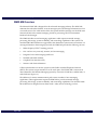
WMG MS Overview
The Motorola WMG MS is designed for the advanced messaging industry. The WMG MS
maintains the subscriber database, receives message inputs, and manages information such as
voice mail services. For valid remote callers, the system sends the message over the Wide Area
Network (WAN) to the remote messaging switch for processing. The local transmitter
broadcasts the messages.
The WMG MS offers several messaging applications which require increased message
processing, file storage, system availability, and networking capabilities of the system. The
modular WMG MS architecture is upgraded as the demand for system resources increases. As
an integral element in the messaging network, the WMG MS provides the following services:
•
Multi-frequency FLEX roaming protocol
•
One- and two-way tone-only, numeric, and text messaging
•
Integrated voice and messaging mail boxes
•
Detailed subscriber database
•
Graphical User Interface (GUI)
•
Statistics and alarm information
Callers and subscribers access the system over the Public Switched Telephone Network
(PSTN). The system accepts standard T1 or E1 trunk spans. Each WMG MS is connected to
other elements in the Wireless Messaging System by a network of land lines, satellite links, or
radio links (see Figure 1-1).
The addition of a return communications path creates a number of new messaging
applications. These applications require the WMG MS to provide increased message
processing, file storage, system availability, and networking capabilities. The modular WMG
MS architecture is designed to meet these needs—today and as technology evolves.
April 1998
6880493G51-A
1-5
Introduction
WMG-Administrator! Messaging Switch Software Installation
Wireless Message GatewayControl Center
RF Management System
Alarm Notification Device
AND-1
Inputs from callers
and subscribers
through the telephone
network
Connection to the
Radio Frequency
(RF) Management
System
To:
From:
Messages to and
from subscribers
r
Teno
Communicators
ON
202-01SRH
WMG-Administrator!
Figure 1-1: The WMG-Administrator! MS and the Wireless Messaging System
WMG MS Subsystems and Peripherals
The following subsystems comprise the WMG MS:
1-6
•
The Central Processor (CP) maintains a copy of the subscriber database (the Operations
and Maintenance Center {OMC} maintains the master subscriber database), messaging,
and routing functions.
•
The UCC provides the interface of the PSTN to the WMG MS using T1 or E1 trunk spans.
•
The File Server controls the storage of voice and data messages using a Redundant Array
of Inexpensive Disks (RAID) system.
•
The (OMC) provides an operator interface through a graphical user interface (GUI) called
the Wireless Message Gateway–Control Center. The WMG MS OMC accesses the
Network Management System through the controller.
6880493G51-A
April 1998
WMG-Administrator! Messaging Switch Software Installation
Introduction
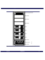
The WMG MS is made up of one or more cabinets, depending on redundancy and capacity
requirements. The third and following cabinets usually contain additional UCC for expanded
messaging capacity (see Figure 1-2 and Figure 1-3).
In a typical redundant system, two cabinets house the standard subsystems, including the
CPs, the OMC, the FS, terminal server(s), and ethernet switches. Each cabinet of the WMG MS
contains a power distribution panel (PDP) and if the site power is –48Vdc, each cabinet
contains a power inverter.
The first cabinet houses the CP, OMC, and the FS. The second cabinet houses up to six (DC
configuration) or seven UCCs (110 or 220 Vac configuration) and ethernet switches. The third
through eleventh cabinets contain only UCCs (seven in the DC configuration, eight in the AC
configuration). If the system comes with the full redundant option, it contains two of the
following subsystems:
•
CP
•
Media converter
•
Ethernet switch
WMG MS also includes the following peripheral devices:
•
Terminal servers
•
Alarm notification device
•
Printers (optional)
•
Power inverter (optional)
April 1998
6880493G51-A
1-7
Introduction
WMG-Administrator! Messaging Switch Software Installation
POWER DISTRIBUTION PANEL
1
2
3
4
5
6
7
8
POWER DISTRIBUTION PANEL
9
10
11
12
1
2
3
4
5
6
7
8
9
10
11
12
Alarm Notification Device
CONTROL
ON
RDY
CMD
MODEM
ALM
OH
AND-1
MONITOR
DCD
DATA
1
2
3
4
Activity
Activity
Activity
Activity
Activity
Activity
Activity
Activity
Activity
Activity
Activity
Activity
Activity
Activity
Activity
Activity
RESET
PWR
PWR
POWER
HD
POWER
POWER
Tx
1
NETWORK
2
3
4
5
6
7
8
9
10
11
12
13
14
15
16
Rx
RESET
POWER
HD
POWER
+5V
a
-5V
+12V
-12V
+5V
RUN
-5V
+12V
-12V
FAN STATUS
RUN
FAIL
FAIL
0
1
2
3
0
1
2
3
ABORT
RESET
ABORT
RESET
KBD/MOUSE
KBD/MOUSE
Blank Panel
10BASE-T
10BASE-T
TTYA/B & AUI
TTYA/B & AUI
LANPLEX
SCSI
SCSI
LANPLEX
RESET
POWER
HD
POWER
RESET
POWER
HD
POWER
HD
POWER
RESET
POWER
HD
POWER
POWER
On
Load
Overload
Load
Overload
Load
Overload
Overload
Load
On
On
On
On
Reset
Reset
Reset
Reset
On
Load
Overload
Load
Overload
Load
Overload
Load
On
On
On
On
Reset
Reset
Reset
Reset
INV On
Load
BRKR Open
On
DC Power On
INV On
Load
INV Fail
INV Fail
Reset
BRKR Open
Reset
HI Temp
HI Temp
FI
1 AMP
FI
1 AMP
ON
ON
CBI
CBI
Reset
Reset
301SRH-127d
Overload
On
DC Power On
Figure 1-2: WMG MS—Typical Redundant DC Powered Two-Cabinet Configuration Without SS7
1-8
6880493G51-A
April 1998
WMG-Administrator! Messaging Switch Software Installation
POWER DISTRIBUTION PANEL
1
2
3
4
5
6
7
8
Introduction
Power Distribution Panel
9
10
11
12
Blank Panel
Blank Panel
Blank Panel
RESET
UCC
POWER
HD
POWER
RESET
UCC
POWER
HD
POWER
UCC
RESET
POWER
HD
POWER
UCC
RESET
POWER
HD
POWER
Blank Panel
On
On
DC Power On
Overload
Overload
Overload
Overload
Load
Load
Load
Load
On
On
On
On
Reset
Reset
Reset
Reset
INV On
Load
Reset
Reset
Power Inverter
HI Temp
FI
1 AMP
ON
CBI
Blank Panel
315SRH-02
INV Fail
BRKR Open
Figure 1-3: WMG MS—Typical DC-Powered Third Cabinet Configuration with Four UCCs
April 1998
6880493G51-A
1-9
Introduction
WMG-Administrator! Messaging Switch Software Installation
Wireless Message Gateway–Control Center
The Wireless Message Gateway–Control Center is the user interface to the WMG MS. Using
the graphical interfaces, system operators can oversee and manage WMG MS operations, such
as system configurations, statistics, alarms, classes of service, and subscriber administration.
Using an x-terminal to access the Wireless Message Gateway–Control Center, operators can
perform the following tasks:
•
Configure system parameters
•
Administer Wireless Message Gateway–Control Center user permissions
•
View WMG MS statistics and alarms
•
Define classes of service and subscriber profiles
The Wireless Message Gateway–Control Center provides the following features:
1-10
•
Operator and group security—The Wireless Message Gateway–Control Center uses
UNIX security procedures for password administration and expiration.
•
Statistics—The Wireless Message Gateway–Control Center collects statistics from each
WMG MS subsystem—CP, UCC, FS, and OMC. The Statistics Viewer produces statistical
reports. The format and content of the reports are configurable.
•
Alarms—The Wireless Message Gateway–Control Center receives and reports alarm
conditions. Alarm conditions have assigned severity levels. Visual indicators alert
operators that alarms have been received. Alarms are stored in log files for later analysis.
•
Configuration—The Wireless Message Gateway–Control Center provides the capability
for managing system configurations, operational service status, and network and
subsystem parameters.
•
Subscriber management—The Wireless Message Gateway–Control Center provides the
capability for managing the subscriber database.
6880493G51-A
April 1998
WMG-Administrator! Messaging Switch Software Installation / Chapter 2
Installing WMG System Software
2
This chapter describes the WMG-Administrator! Messaging Switch (WMG MS) software
installation for Version 3.1.
WMG MS Software Installation Overview, 2-3
Software Used by the WMG MS, 2-3
System Software, 2-4
Installing the Operating System,
2-4
Configuring the X-Terminal, 2-7
Setting the OMC Serial Connection,
2-11
Installing the OMC Operating System and Database, 2-13
Setting the OMC Open Boot Parameters, 2-13
Defining the OMC System Identification and Configuration,
Installing the OMC Load Tape, 2-21
Disconnecting the OMC CD-ROM (Themis Systems), 2-23
Configuring the Terminal Server, 2-25
Terminal Server Configuration, 2-26
Terminal Server Configuration for TNPP (optional),
2-17
2-31
Configuring the Ethernet Switch, 2-36
Setting the Ethernet Switch System Level Parameters, 2-37
Setting the Ethernet Switch Bridge Level Parameters, 2-38
Setting IP Level Parameters, 2-39
Configuring File Server Software,
Setting Up the FS, 2-42
2-42
Local Printer Setup, 2-47
Setting up the HP 4MP, 2-47
Setting up the HP 5M, 2-49
Defining a Network Printer, 2-53
Installing the WMG CP Operating System, 2-55
Loading CP1 Tape and Boot CD-ROM, 2-55
Setting the CP1 Open Boot Parameters, 2-57
Setting the Open Boot Parameters, 2-58
Identifying the CP1 System, 2-59
Loading the CP1 Installation Tape, 2-64
April 1998
6880493G51-A
2-1
Installing WMG System Software
WMG-Administrator! Messaging Switch Software Installation
Disconnecting the CP1 CD-ROM,
2-66
Loading WMG Applications, 2-68
Overview, 2-68
File Server Configuration, 2-68
OMC System Application Installation, 2-69
Creating the OMC Database, 2-69
CP1 or CP2 System Application Installation, 2-70
Installing the UCC System Application, 2-71
2-2
6880493G51-A
April 1998
WMG-Administrator! Messaging Switch Software Installation
Installing WMG System Software
WMG MS Software Installation Overview
The factory installs and configures software and for the WMG MS subsystems and
peripherals. In some cases, software must be loaded at the site for upgrades, system
expansion, or troubleshooting. This chapter provides procedures for loading the WMG MS
software including the Solaris version operating system, and software for the following
subsystems:
•
X-terminal
•
Operation and Maintenance Center (OMC), Central Processor (CP) 1, CP2
•
Terminal Server (TS)
•
File Server (FS)
Software Used by the WMG MS
The WMG MS uses the following vendor software for processing and managing messages:
•
Solaris operating system for the CP
•
Informix for the system database
•
Network Appliance for the FS
Special Precautions and Instructions
•
Prior to starting any procedure, check that all calibration stickers on the test equipment
are current.
•
Equipment can be damaged by improper cable installation. Ensure that cables are
correctly oriented with their jacks prior to mating.
•
Adhere to all warnings on equipment and in operating instructions.
•
Always observe static safety precautions when handling static sensative parts.
April 1998
6880493G51-A
2-3
Installing WMG System Software
WMG-Administrator! Messaging Switch Software Installation
System Software Installation—Required Materials
At the system level, the WMG MS uses the Solaris operating system and the Informix database
software. Most of the installation and configuration of the operating system and database is
performed using an automated WMG MS installation script.
The WMG MS uses preset (factory default) Internet Protocol (IP) addresses to define the
Control LAN, Voice LAN, OMC LAN and RF-Conductor! (RF-C!) LAN. Appendix B lists the
default IP addresses, host names, and configuration drawings to use when installing WMG
software. To modify system IP addresses, use the vi text editor or other editor of your choice.
(consult your network administrator) The address values and host names are located on the
CP1, CP2, and the OMC in the /etc/hosts file.
Note:
CAUTION
Use the customer’s IP plan when makeing changes to the /etc/hosts file to avoid installation
errors. The installation of some applications require that the IP address for that host be
identified at the time of installation. Changing the IP address of that host at a later time may
require that the application be reinstalled.
Following the procedures in this chapter overwrites existing files, data, and system
configuration information.
Required Tools and Equipment for Themis/SPARC 20-based Systems
Assemble the following items to perform the software installation procedures for
Themis/SPARC 20-based systems:
•
External CD-ROM drive–
– External or stand-alone CD-ROM drive configured for use with the Openboot
EEPROM
– SCSI-2 cabling for the external SCSI-2 connection on the back of the CP VME chassis
– SCSI termination appropriate for the CD-ROM drive
•
Software Media–
– Solaris CD-ROM version 2.5.1, Hardware (8280520F33); SunSoft label information:
May 1996, Part #704–5235–10, Revision A
– WMG installation tape–Package Load DAT Tape (0180302F82)
2-4
6880493G51-A
April 1998
WMG-Administrator! Messaging Switch Software Installation
•
X-terminal supplied with the system
•
Serial cable made of the following three parts–
Installing WMG System Software
– Motorola Part #5880567S01 DB25-RJ45 adapter
– Motorola Part #5880550S01 DB9-RJ45 adapter
– Motorola Part #0180301F97 serial RJ45-RJ45 cable kit
•
Software license information for the following–
– Solaris ID and system environment ID
– Informix keycards
– Report Writer
– WMG Application licenses
Required Equipment for Sun Ultra-based systems
Assemble the following items to perform the software installation procedures for Ultra-based
systems:
•
Software Media–
– Solaris CD-ROM version 2.5.1, Hardware (8280520F33); SunSoft label information:
May 1996, Part #704–5235–10, Revision A
–
The WMG installation tape–Package Load DAT Tape (0180302F82)
•
X-terminal supplied with the system
•
Serial cable made of the following three parts–
– Motorola Part #5880567S01 DB25-RJ45 adapter
– Motorola Part #5880550S01 DB9-RJ45 adapter
– Motorola Part #0180301F97 serial RJ45-RJ45 cable kit.
•
Software license information for the following–
– Solaris ID and system environment ID
– Informix keycards
– Report Writer
– WMG application licenses
•
WMG MS release notes
Software is continually changing, and the release notes may contain important
information that is not in this book.
April 1998
6880493G51-A
2-5
Installing WMG System Software
WMG-Administrator! Messaging Switch Software Installation
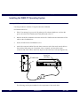
Configuring the X-Terminal
The x-terminal is the display interface for the WMG Control Center. The WMG Control Center
is a Graphical User Interface (GUI) for issuing commands, setting up system parameters, and
generating reports. The WMG MS x-terminal has two configuration environments, the NCD
windows environment and the NCD Boot Monitor. The windows environment is a GUI, and
the Boot Monitor is menu driven. The initial configuration of the x-terminal in this procedure
occurs in the Boot Monitor. Later procedures in the WMG MS configuration occurs through
the windows environment.
Use the following procedures to configure the x-terminal:
1.
Power up the x-terminal.
The NCD windows environment appears.
2.
Press the following keys at the same time: <Ctrl+Left Alt> and <Setup>
The Boot Monitor command line prompt appears.
3.
4.
Load the default values:
a.
Type nv <Return>
b.
Type L <Return>
c.
Type S <Return>
d.
Type Y <Return>
e.
Type q <Return>
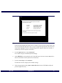
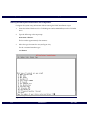
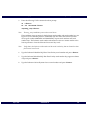
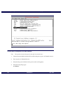
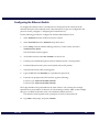
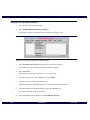
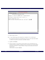
Press <Setup> at the Boot Monitor prompt.
The Boot Monitor main menu appears (see Figure 2-1).
2-6
6880493G51-A
April 1998
WMG-Administrator! Messaging Switch Software Installation
Help
Keyboard
Installing WMG System Software
Monitor
Network
Boot
Done
Help
Use the arrow keys to navigate through the menus listed
across the top of the screen:
Left, Right
Up, Down
Control-U
Escape
Go to previous or next menu.
Go to previous or next field
within the current menu.
Delete to beginning of line.
Restore previous value.
Help for each field within a menu is shown along the bottom
of the screen.
301SRH-53
Exit via the Done menu at the right of the screen.
Figure 2-1: Boot Monitor Main Menu
The main menu displays the names of the six menus. To move from one menu item to the
next, use the left and right arrow keys. As you navigate through the menu bar, the active
menu name highlights, and the corresponding window displays. Below the window, a
smaller help window displays instructions.
5.
Use the right arrow key to select Keyboard.
The window displays available keyboard settings.
6.
Select IBMPS/2 if your keyboard is the N-101 MPS type, otherwise select n-101 (See the
label on the bottom of the keyboard for information).
7.
Press the arrow keys to select Monitor.
The Monitor window displays the available settings.
8.
April 1998
Select the appropriate setting (1280 x 1024 70 Hz color for the NCD HMX model) and
press the right arrow key.
6880493G51-A
2-7
Installing WMG System Software
WMG-Administrator! Messaging Switch Software Installation
The Dots Per Inch pop-up menu appears.
9.
Change the dots per inch setting to 100.
10. Press the right arrow key to select Network.
The Network window displays the current network settings.
11. Press spacebar until NVRAM selection is highlighted.
12. Configure the network settings as follows:
a.
Enter the terminal (omcterm1 or omcterm2) IP address–
- Type 10.5.0.16 if this NCD is omcterm1.
- Type 10.5.0.17 for omcterm2 .
b.
Enter the first boot host IP address; type 10.5.0.2
c.
Use the default value of 0.0.0.0 for the second boot host IP address; type 0.0.0.0.
d.
Use the default value of 0.0.0.0 for the third boot host IP address; type 0.0.0.0.
e.
Enter the gateway IP address; type 0.0.0.0.
f.
Make the subnet mask a C class IP; type 255.255.0.0.
g.
Enter the broadcast IP address; type 10.5.255.255.
h.
Use the default for the Terminal NCDnet address; type 0.0.
i.
Use the default for the Host NCDnet Address; type 0.0.
j.
Use the default for the Router NCDnet Address; type 0.0.
k.
Press the spacebar until No for SNAP (802.2 Encapsulation) is highlighted.
ALL IP addresses used in this manual are the factory default values and are not suitable for use
as the customer-specific IP addresses needed to configure the WMG MS system. You must
have the customer IP address plan to continue the configuration and installation process.
CAUTION
13. Use the right arrow key to select Boot from the top of the menu and the Unix Config
Directory.
a.
2-8
Type /usr/local/wmg/config/<Return>.
6880493G51-A
April 1998
WMG-Administrator! Messaging Switch Software Installation
Note:
Installing WMG System Software
Be certain to enter the trailing slash (/).
b.
Use the arrow keys to highlight the TFTP selection.
c.
For TFTP Order, use the default of 2.
d.
For NFS Order, press D to disable.
e.
For MOP Order, press D to disable.
f.
For LOCAL, use the default of 1.
14. Use the right arrow key to select Done from the top of the main menu.
15. Select Reboot. The following prompt appears:
Save Parameters and reboot. Press <Return> to confirm .
16. Press <Return> to save the settings and reboot.
The x-terminal reboots and displays the NCD windows environment window.
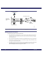
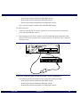
Setting the OMC Serial Connection
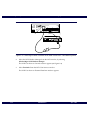
1.
Connect a serial cable from the NCD x-terminal to the OMC console port ttya (see Figure
2-2 and Figure 2-3).
Serial Port
(Auxillary)
AUDIO IN
AUXILIARY
TWISTED PAIR
PARALLEL
MONITOR
PARALLEL
MOUSE
KEYBOARD
AUDIO
OUT
351SRH-02
THIN
PORT/LINK
LED
0 1 2 3
Serial Port
Figure 2-2: Connecting the NCD X-Terminal to the OMC TTYA/B Port—Themis Systems
April 1998
6880493G51-A
2-9
WMG-Administrator! Messaging Switch Software Installation
TTYA
351SRH-01
Installing WMG System Software
Serial Port
(Auxillary)
AUDIO IN
AUXILIARY
THIN
TWISTED PAIR
PARALLEL
MONITOR
PARALLEL
MOUSE
KEYBOARD
AUDIO
OUT
Figure 2-3: Connecting the NCD X-terminal to the OMC console Port—Ultra-Based Systems
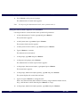
2.
Select the NCD Window Manager from the NCD window, by selecting
WindowMgr>NCD Window Manager.
The NCD User Services: Console window appears (see Figure 2-4).
3.
Select Terminals From the NCD User Services window.
The NCD User Services: Terminal Emulator window appears.
2-10
6880493G51-A
April 1998
WMG-Administrator! Messaging Switch Software Installation
Installing WMG System Software
Figure 2-4: NCD User Services Console Window
4.
Select serial port.
The connecting to serial port 1...success message displays.
5.
From the Serial window, select Fonts, then select Jumbo.
6.
Push the power distribution panel switch for the OMC to ON position.
7.
Turn the OMC power switch on:
– For Themis-based systems, the power switch is on the front side.
– For Ultra-based systems, the power switch is on the back side.
Openboot diagnostic messages begin to scroll in the NCD Terminal window.
8.
When the RAM test and initialization begins, press <Break>
The system responds with an ok prompt.
April 1998
6880493G51-A
2-11
Installing WMG System Software
WMG-Administrator! Messaging Switch Software Installation
Installing the OMC Operating System and Database
The WMG installation script performs most of the installation automatically, though some
configuration information must be entered manually. The installation script handles the
following tasks:
•
Solaris
– Formatting the disk drive type
– Installing the Solaris software
– Installing Solaris patches
•
IP address definition
•
Informix
– Installing the ESQL (run time) and Dynamic Server (run time) tapes
There are two phases to the Solaris and Informix installation process:
•
Defining system identification and configuration
•
Running the OMC installation script
Note:
The OMC installation requires a CD-ROM caddy.
Setting the OMC Open Boot Parameters
1.
Reset NVRAM to factory defaults by typing:
set-defaults <Return>
2.
At the ok prompt, reboot the processor board by typing:
reset <Return>
3.
During the RAM tests, press <Break>.
The system responds with the ok prompt.
4.
Change the TTYA-mode parameter. Type the following at the ok prompt:
setenv ttya-mode 9600,8,n,1,s <Return>.
5.
2-12
At the ok prompt, type
6880493G51-A
April 1998
WMG-Administrator! Messaging Switch Software Installation
Installing WMG System Software
setenv diag-switch? true <Return>
6.
Change the diag-service parameter by typing the following at the ok prompt:
– For Themis-based systems, type:
setenv diag-device fastdisk <Return>
– For Ultra-based systems, type:
setenv diag-device disk <Return>
For Ultra-based systems skip to Step 13.
7.
At the ok prompt, type:
setenv boot-device fastdisk <Return>
8.
Modify the NVRAM at the ok prompt, by typing
nvedit <Return>.
9.
At line 0, type the following:
devalias fastdisk /iommu@f,e0000000/sbus@f,e0001000/QLGC,isp@1,10000/sd@3,0
<Return>
10. Press <Ctl+C> to exit nvedit.
11. Store the NVRAM changes; type:
nvstore <Return>
12. At the ok prompt, type:
setenv use-nvramrc? true <Return>
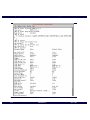
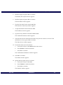
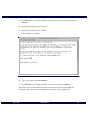
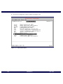
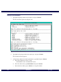
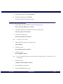
13. At the ok prompt, type
printenv <Return>
The OMC parameters window displays. Verify that the information in the OMC
parameters window is correct (see Figure 2-5).
14. Repeat this procedure to correct any errors.
April 1998
6880493G51-A
2-13
Installing WMG System Software
WMG-Administrator! Messaging Switch Software Installation
Figure 2-5: Openboot Parameters for OMC
2-14
6880493G51-A
April 1998
WMG-Administrator! Messaging Switch Software Installation
Installing WMG System Software
15. Reboot the system at the ok prompt; type:
reset <Return>
16. Press <Break> during the RAM tests.
The system responds with the ok prompt.
17. Verify that the system SCSI IDs are properly set; type:
probe-scsi-all <Return>
For Ultra-based systems, type Y <Return> to continue.
18. Verify the following settings:
– For Themis-based systems–
- target 3: OMC disc drive
- target 4: 4-mm DAT tape drive
- target 6: external CD-ROM drive
– For Ultra-based systems–
- target 0: OMC disk drive
- target 4: 4-mm DAT tape drive
- target 6: external CD-ROM drive
This completes setting the OMC open boot parameters.
April 1998
6880493G51-A
2-15
Installing WMG System Software
WMG-Administrator! Messaging Switch Software Installation
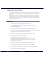
Defining the OMC System Identification and Configuration
Configure the system setup information before running the WMG installation scripts:
1.
Insert the Solaris Hardware 2.5.1 CD-ROM (part number 8280520F33) into the CD-ROM
drive.
2.
Type the following at the ok prompt:
boot cdrom <Return>
The boot takes approximately four minutes.
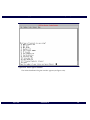
3.
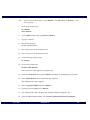
Select the type of terminal in use (see Figure 2-6).
For the x-terminal emulator type:
12 <Return>
Figure 2-6: Terminal Selection
2-16
6880493G51-A
April 1998
WMG-Administrator! Messaging Switch Software Installation
4.
Installing WMG System Software
Read the display and press <F2> to continue.
The Identify This System window appears.
5.
Read the display and press <F2> to continue.
The Host Name window appears.
6.
Type the host name for the system: omc <F2>.
The Network Connectivity window appears.
7.
Accept the default for Networked: Yes <F2>.
The IP Address window appears.
8.
Type the factory default for the OMC: 10.5.0.2 <F2>.
The Confirm Information window appears.
9.
Verify that the network information entered in the previous windows is correct. If the
information is correct, press <F2> to continue.
The Name Service window appears.
10. Provide the name service information:
a.
Use the arrow keys to select None for the name service.
b.
Press <Return> to mark the selection.
c.
Press <F2> to continue.
The Confirmation Information windows appears.
11. Press<F2> to continue.
The Subnets window appears.
12. Specify that the system is part of a subnet:
a.
Use the arrow keys to select Yes.
b.
Press <Return> to mark the selection.
c.
Press <F2> to continue.
The Netmask window appears.
April 1998
6880493G51-A
2-17
Installing WMG System Software
WMG-Administrator! Messaging Switch Software Installation
13. Define the netmask of the subnet.
a.
Enter the subnet value in the Netmask field that corresponds to the internet class IP
address by typing 255.255.0.0 <F2>.
The Time Zone Region window appears.
14. Specify the default time zone:
a.
Use the arrow keys to select the appropriate country value, then press <Return>.
b.
Use the arrow keys to select the appropriate time zone file, then press <Return>.
The Date and Time window appears.
c.
Enter the appropriate date and time for the selected country.
The Confirm Information window appears.
15. Verify that the information entered on the previous windows is correct.
16. Press <F4> to make changes, if needed.
17. Press <F2> to continue.
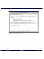
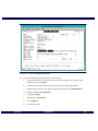
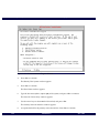
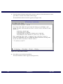
18. After confirming the information by pressing <F2>, the Install Solaris Software—Initial
window appears. (see Figure 2-7)
Note:
Wait until the CD-ROM finishes reading the CD. This takes approximately two minutes.
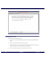
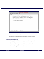
19. Press <F5> to exit Solaris installation and to begin the WMG installation script.
The Exit Installation window appears (see Figure 2-8).
20. Press <F2> to exit Solaris installation.
Note:
The system saves all information defined until to this point.
The system displays the # prompt. The WMG installation script is ready for execution.
2-18
6880493G51-A
April 1998
WMG-Administrator! Messaging Switch Software Installation
Installing WMG System Software
Figure 2-7: Install Solaris Software—Initial
April 1998
6880493G51-A
2-19
Installing WMG System Software
WMG-Administrator! Messaging Switch Software Installation
Figure 2-8: Exit Solaris Installation Window
Installing the OMC Load Tape
Use this procedure to load the OMC tape:
2-20
1.
Verify that the 4-mm DAT installation tape is the correct part number (0180302F82) and
version.
2.
Verify that the 4-mm DAT cartridge is write protected.
3.
Verify that the Informix version number for the serial number and the serial number key
matches the Informix version in the installation script prompt.
4.
Insert the installation tape into the 4-mm DAT tape drive of OMC.
6880493G51-A
April 1998
WMG-Administrator! Messaging Switch Software Installation
5.
Installing WMG System Software
Enter the following UNIX commands at the # prompt:
cd / <Return>
tar -xvf /dev/rmt/0lb <Return>
/tmp/wmg_setup <Return>
Note:
The wmg_setup installation process takes several hours.
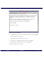
The installation script prompts for the Informix serial number and serial number key (see
Figure 2-9). Two Informix products, Embedded SQL Run Time and OnLine Dynamic
Server (part number 8280520F25 and 8280520F24), require serial numbers and serial
number keys. The Informix serial number information comes in a manner similar to the
license quantities—from the Informix license and key cards.
Note:
Verify that in the Informix serial number and the serial number key that are identical to those
found on the license cards.
6.
Type the Informix Embedded SQL Run Time Facility serial number and press <Return>.
7.
Type the Informix Embedded SQL Run Time Facility serial number key (uppercase letters
only) and press <Return>.
8.
Type the Informix-OnLine Dynamic Server serial number and press <Return>.
April 1998
6880493G51-A
2-21
Installing WMG System Software
WMG-Administrator! Messaging Switch Software Installation
Figure 2-9: Information Installation Script Menu
9.
Type the Informix-OnLine Dynamic Server serial number key (uppercase letters only)
and press <Return>.
10. Define IP addresses for WMG standard host names. Press <Return> at each prompt to
accept defaults.
The license type codes, Informix, and IP addresses for WMG MS standard host names are
now defined. The WMG installation script formats the disc drive and loads the OMC.
After all WMG MS software is installed, the system reboots from the disc drive. The
WMG MS system default IP addresses are contained in Appendix B.
Note:
This section takes approximately four hours to complete.
The Root Password window appears (see Figure 2-10).
2-22
6880493G51-A
April 1998
WMG-Administrator! Messaging Switch Software Installation
Installing WMG System Software
11. Type motorola (or a customer specified root password) as the root password and press
<Return>.
12. Record the root password for future use.
13. Repeat the password entry to confirm.
The installation is complete.
Figure 2-10: Root Password Window
14. Log in to the OMC; type root <Return>.
15. Type motorola (or a customer specified root password) and press <Return>.
After defining the system identification and configuration and running the WMG MS
installation script, disconnect the CD-ROM drive using the following procedure.
April 1998
6880493G51-A
2-23
Installing WMG System Software
WMG-Administrator! Messaging Switch Software Installation
Disconnecting the OMC CD-ROM (Themis-Based Systems)
Disconnect the CD-ROM drive using the following procedure:
1.
Eject the DAT tape and CD-ROM disk while using the same NCD terminal emulator
window as in the previous installation.
a.
Eject the DAT tape by typing the following in the NCD terminal emulator window:
mt -f /dev/rmt/0lb rewoffl <Return>
a.
Eject the CD-ROM disk by typing the following in the NCD terminal emulator
window:
eject <Return>
2.
Log out of the OMC by typing:
exit <Return>
3.
Wait for the OpenBoot ok prompt.
4.
Turn off the power to the CD-ROM and OMC.
DANGER
Power down the CD-ROM and the OMC before disconnecting the
serial console cable.
5.
Disconnect the serial console cable.
6.
Power up the OMC.
7.
Press <Setup> to display the NCD User Services window after the OMC boots.
8.
Select the Console option.
9.
Select Reboot in the NCD Console Window.
The x-terminal reboots.
2-24
6880493G51-A
April 1998
WMG-Administrator! Messaging Switch Software Installation
Installing WMG System Software
Configuring the Terminal Server
The terminal server provides the serial connections for the WMG MS subsystem components.
Specific keys on the keyboard control the navigation through the terminal server user
interface windows and menus (see Table 2-1).
Table 2-1: Terminal Server Navigation Keys
Menu Key
Description
Left Arrow
Moves the cursor left
Right Arrow
Moves the cursor right
Up Arrow
Moves the cursor up
Down Arrow
Moves the cursor down
<Tab>
Moves the cursor right
<Back Space>
Moves the cursor back one field or deletes a character depending on how
the user configures this key
<Del>
Deletes a character
<Spacebar>
Toggles through the options for a particular field
<Return>
Selects the option the cursor is positioned on or selects the list of options
from the Connections Menu
<Esc>
Cancels the current command or takes the user back one menu
April 1998
6880493G51-A
2-25
Installing WMG System Software
WMG-Administrator! Messaging Switch Software Installation
Terminal Server Configuration
Use the following procedure to configure the terminal server:
Note:
Power to the terminal server must be shut off before starting this procedure.
10. Use an RJ-45-DB9 adapter (part number 58R80550S01) and a null modem to connect the
serial cable from the NCD console serial port to port 1 on Terminal Server 1.
11. Push the PDP switch for Terminal Server 1 to the ON position.
12. Push the Terminal Server 1 power switch to on.
Note:
This is the down position.
13. Verify that the Power indicator light is on (green).
14. From the login prompt, type:
su <Return>
Note:
If the Connections Menu appears, press <Return> and select CLI and press <Return> to get
to the local prompt
15. At the local prompt, type the following login sequence:
su <Return>
iolan <Return>
16. At the ADMIN:local prompt, type the following sequence:
facreset <Return>
y <Return>
Wait for the message: System is Shutting Down message
17. Turn off the power to the terminal server.
18. Turn on the power to the terminal server.
2-26
6880493G51-A
April 1998
WMG-Administrator! Messaging Switch Software Installation
Installing WMG System Software
19. At the local login prompt, type the command:
su <Return>
20. At the local prompt, type the command:
set term vt100 <Return>
The Connections menu appears.
21. Press <Return> from the Connections menu to display the Commands pop-up menu.
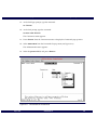
22. Select Admin Mode from the Commands Pop-up menu (see Figure 2-11).
The Administration menu appears.
23. Select the password field, and press <Return>.
Figure 2-11: Terminal Server Connections
April 1998
6880493G51-A
2-27
Installing WMG System Software
WMG-Administrator! Messaging Switch Software Installation
24. Type the password (iolan is the default password) and press <Return>.
The Administration menu displays with additional fields.
25. Select server: Examine/modify Server parameters from the Administration menu, and
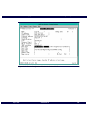
press <Return> (see Figure 2-12).
The Server Configuration window appears (see Figure 2-13).
Figure 2-12: Administration Menu
2-28
6880493G51-A
April 1998
WMG-Administrator! Messaging Switch Software Installation
Installing WMG System Software
Figure 2-13: Server Configuration Window for Version 3.5.02
April 1998
6880493G51-A
2-29
Installing WMG System Software
WMG-Administrator! Messaging Switch Software Installation
Figure 2-14: Server Configuration Window for Version 4.00.19
26. Define the following parameters in the Server Configuration window:
2-30
a.
Name: enter a name for the terminal server that matches the host name of the
terminal server; type: tserv1.
b.
IP address: enter the IP address of the terminal server; type: 177.4.77.35 .
c.
Subnet mask: enter the value that corresponds with the IP; type: 255.255.255.0 .
d.
Ethernet Address: Accept default
e.
Language: English or the appropriate language.
f.
Identification : leave blank
g.
Lock : Disabled
h.
Password limit: 5 (change if desired)
i.
CR to initiate : Yes
6880493G51-A
April 1998
WMG-Administrator! Messaging Switch Software Installation
j.
SNAP encoding: Disabled
k.
Boot host: Type 177.4.77.17
l.
Boot file : leave blank
-
Installing WMG System Software
For IOLAN v3.5.02: leave blank
For IOLAN v4.00.19: /usr/local/wmg/config/iolan40019.boot
m.
Init file : (modify, the path to the terminal server configuration file on the CP)
- For IOLAN v3.5.02: /usr/local/wmg/config/iolan3502.config
- For IOLAN v4.00.19: /usr/local/wmg/config/iolan40019.config
n.
Domain name : leave blank
o.
Name server: leave blank
27. Press <Return>.
28. Select Save & Exit from the Commands pop-up menu, and press <Return>.
The Administration menu appears.
29. Select reboot: Reboot Server, press <Return>, then press the <Spacebar> (see Figure
2-15).
The message ***Terminal Server Shutdown in progress*** appears. If the reboot is
successful, the message Image Load Complete appears, and the terminal server login
prompt displays (tserv1>).
30. Disconnect the cable going from Port 1 on the back of the Terminal Server and the NCD
serial port.
This completes the procedure for configuring the WMG MS terminal.
Repeat the above procedure for the remaining terminal servers using the corresponding IP
addresses (see Appendix B).
April 1998
6880493G51-A
2-31
Installing WMG System Software
WMG-Administrator! Messaging Switch Software Installation
Figure 2-15: Administration Menu
Terminal Server Configuration for TNPP (optional)
Note:
This procedure assumes that power is shut off to the terminal server.
1.
Connect the serial cable from the NCD console serial port to port 1 on Terminal Server 2.
2.
Turn on power to Terminal Server 2.
3.
Verify that the power indicator on the power switch is ON (green).
4.
From the local prompt, type:
su <Return>
2-32
6880493G51-A
April 1998
WMG-Administrator! Messaging Switch Software Installation
Note:
5.
Installing WMG System Software
If the Connections Menu appears, press <Return>, select CLI, then press <Return> to get to
the local prompt
At the local prompt, type:
su <Return>
iolan <Return>
6.
At the ADMIN:local prompt, type facreset <Return>.
7.
Type y to continue.
8.
Wait for the message:
System is Shutting Down
9.
Turn off the power to the terminal server.
10. Turn on the power to the terminal server.
11. At the local login prompt, type:
su <Return>
12. At the local prompt type:
set term vt100 <Return>
The Connections menu appears (see Figure 2-11).
13. From the Connections menu, press <Return> to display the Commands pop-up menu.
14. Select Admin Mode from the Commands pop-up menu.
The Administration menu appears.
15. Select the password field and press <Return>.
16. Type the password iolan, press <Return>.
17. The Administration menu displays with additional fields (see Figure 2-16).
18. From the Administration Menu, select server: Examine/modify Server parameters.
April 1998
6880493G51-A
2-33
Installing WMG System Software
WMG-Administrator! Messaging Switch Software Installation
19. The Server Configuration window appears (see Figure 2-17).
Figure 2-16: Administration Menu
2-34
6880493G51-A
April 1998
WMG-Administrator! Messaging Switch Software Installation
Installing WMG System Software
Figure 2-17: Server Configuration window
20. Enter the following information in the relevant fields:
April 1998
a.
Name: enter a name for the terminal server that matches the “host name” of the
terminal server; type tserv2
b.
IP address: enter the IP address of the terminal server: Type 177.4.77.36
c.
Subnet mask: enter the value that corresponds with the IP: Type 255.255.255.0
d.
Ethernet Address: Accept default
e.
Language: English
f.
Identification: leave blank
g.
Lock: Disabled
h.
Password limit: 5
6880493G51-A
2-35
Installing WMG System Software
WMG-Administrator! Messaging Switch Software Installation
i.
CR to initiate: Yes
j.
SNAP encoding: Disabled
k.
Boot host: 177.4.77.17
l.
Boot file: /usr/local/wmg/config/iolan3502_vblck16.boot
m.
Init file: leave blank
n.
Domain name: leave blank
o.
Name server: leave blank
21. Press <Return> then select Save & Exit from the Commands Pop-up menu.
22. Press <Return>.
The Administration menu appears (see Figure 2-15).
23. Select reboot: Reboot Server, press <Return>, then press the spacebar.
The message ***Terminal Server Shutdown in progress*** appears. If the reboot is successful,
the message Image Load Complete appears and the terminal server login prompt is displayed
(tserv2>).
24. Disconnect the cable going from Port 1 on the back of the Terminal Server the to NCD
serial port.
This completes the procedure for configuring the terminal server
25. After all the terminal servers are configured close the NCD widow.
2-36
6880493G51-A
April 1998
WMG-Administrator! Messaging Switch Software Installation
Installing WMG System Software
Configuring the Ethernet Switch
To configure the ethernet switch, a terminal server serial port must be connected to the
terminal serial port on the ethernet switch. This terminal server port was configured in the
previous section, paragraph, "Configuring the Terminal Server").
Use the following procedure to configure the LanPlex 2500 ethernet switch:
1.
Select Terminals from the NCD User Services window.
2.
Select New Telnet from the Terminals drop-down menu.
3.
Press <Setup> from the Wireless Message Gateway -Control Center, and select
Terminals>New Telnet.
The NCD Telnet window appears.
4.
At the telnet window enter omc <Return> for the service.
5.
Push the power distribution panel switch for Ethernet Switch 1 to ON position.
6.
Push the Ethernet Switch 1 power switch (back side) to ON position
7.
Verify that the Power LEDs are ON (green)
8.
Login as root and enter motorola (or a specified root password).
9.
From the omc prompt in the NCD window, type the following:
For enet 1 type: telnet tserv1 10005 <Return>
For enet 2 type: telnet tserv1 10006 <Return>
The 5-digit number is the port number in the form of 100xx, with xx being the two-digit
terminal server port number; for instance, 06. The resulting would be 10006, in this example.
(The port # is 10005 for ethernet switch 1 and 10006 for ethernet switch 2.)
The ethernet switch responds with a prompt for access level and password.
10. Type adm at the prompt, and press <Return>.
April 1998
6880493G51-A
2-37
Installing WMG System Software
WMG-Administrator! Messaging Switch Software Installation
11. Press <Return> at the password prompt.
The Administrative Console menu appears.
Note:
For help using the Administrative Console, enter a question mark (?).
Setting the Ethernet Switch System Level Parameters
Use this procedure to set the ethernet switch system level parameters.
1.
At the Administrative Console, type sys and press <Return>.
The System menu appears.
2.
At the System menu: type nvD and press <Return>.
The System nvData window appears.
3.
At the System nvData window, type reset and press <Return>.
4.
Type Y <Return> to continue.
The ethernet switch will reboot.
5.
At the prompt, type adm and press <Return>.
6.
At the password prompt, press <Return>.
The Administrative Console top-level menu appears.
7.
At the prompt, Select a menu option:, type sys and press <Return>.
The System menu appears.
8.
At the prompt, Select menu option (system):, type tim and press <Return>.
The system displays the current date and time.
9.
Type Y and press <Return> to change the time.
Enter a new date and time (12hr format) if necessary, using the default format of mm/
dd/yy and hh:mm:ss AM or PM and press <Return> to accept.
10. At the prompt, Select menu option (system):, type nam and press <Return>.
2-38
6880493G51-A
April 1998
WMG-Administrator! Messaging Switch Software Installation
Installing WMG System Software
11. At the prompt, Select menu option (system):, type the system name and press <Return>.
Type enet1 for ethernet switch 1, or enet2 for ethernet switch 2.
12. At the prompt, Select menu option (system):, type q and press <Return> to return to the
previous level menu.
Setting the Ethernet Switch Bridge Level Parameters
Use this procedure to set the ethernet switch bridge level parameters.
1.
At the prompt, Select a menu option:, type bri and press <Return>.
The Bridge menu appears.
2.
At the prompt, Select menu option (bridge):, type stpS and press <Return>.
3.
The system prompts to enter a new value (disabled or enabled); type ena and press
<Return>.
4.
At the prompt, Select menu option (bridge):, type stpM and press <Return>.
5.
The system prompts to enter a new value [20]; type 6 and press <Return>.
6.
At the prompt, Select menu option (bridge):, type stpF and press <Return>.
7.
The system prompts to enter new value [15]; type 4 and press <Return>.
April 1998
6880493G51-A
2-39
Installing WMG System Software
WMG-Administrator! Messaging Switch Software Installation
Setting IP Level Parameters
1.
Type ip at the prompt, Select a menu option:, and press <Return>.
The IP Level menu appears (see Figure 2-18).
Figure 2-18: IP Level Parameters
2.
Type inter at the prompt, Select menu option (ip):, and press <Return>.
The IP/Interface menu appears.
3.
2-40
At the prompt, Select menu option (ip/interface):, type def and press <Return>.
a.
Enter the IP address for enet1 or enet2:
- 177.4.77.30 for enet1 or 177.4.77.31 for enet2
b.
Enter the subnet mask, type 255.255.255.0 and press <Return>.
c.
Enter broadcast address, press <Return> to accept the default.
6880493G51-A
April 1998
WMG-Administrator! Messaging Switch Software Installation
4.
Installing WMG System Software
d.
Enter the cost, press <Return> to accept the default of 1.
e.
Select all and press <Return>
f.
Type q to return to the Select Main option (ip) window
g.
Select in to enter ip/interface window
Type dis and press <Return>.
The system displays the defined IP parameters.
5.
Verify the IP parameters for each of the subnets.
6.
At the prompt, Select menu option (ip/interface):, type q and press <Return> to return to
the previous menu.
7.
At the prompt, Select menu option (ip):, type rip and press <Return>.
8.
The system displays Enter RIP mode (off, passive, active); type off and press <Return>.
9.
At the prompt, Select menu option (ip):, type ping and press <Return>.
10. Enter the destination IP address to ping, type 177.4.77.17 and press <Return>.
The enet responds that the address is alive.
11. At the prompt, Select menu option (ip):, type q and press <Return> to return to the
previous level menu.
12. At the prompt, Select menu option:, type sys and press <Return> to return to the
previous level menu.
The Administrative Console top level menu appears.
13. At the prompt, Select menu option (system):, type reb and press <Return>.
14. Type y for yes to reboot the system and press <Return>.
15. Exit from the terminal session; type Ctl-]
16. At the telnet > prompt, type quit.
April 1998
6880493G51-A
2-41
Installing WMG System Software
WMG-Administrator! Messaging Switch Software Installation
You have now completed the ethernet switch software configuration to the specifications
of the WMG MS.
Note:
2-42
Repeat this procedure for each ethernet switch in the system.
6880493G51-A
April 1998
WMG-Administrator! Messaging Switch Software Installation
Installing WMG System Software
Configuring File Server Software
To configure the File Server (FS), connect a terminal server serial port to the serial console port
on the file server. This terminal server port was configured in terminal server configuration
procedures.
Before configuring the FS, ensure that both Power Distribution Panel switches are turned on
for the FS. There is one power circuit for the Redundant Array of Independent Disks (RAID)
and a separate power circuit for the system controller. If possible, power up the RAID before
applying power to the controller.
Setting Up the FS
1.
Insert Network Appliance System Bootup Disk version 3.1.4d.
2.
From the Terminal Emulator window, at the omc prompt type the following:
telnet tserv1 10004 <Return>
3.
Push the power distribution switch for Disk Storage (RAID) to the ON position.
4.
Verify that both disk storage power supply LEDs (left front above power connector, top is
shelf status, bottom is power supply status) are ON (green)
5.
Push the power distribution panel switch for the file server to ON position.
6.
Push the file server power switch to ON position.
7.
Verify that the file server LED status is as follows:
Left LED (Active) is OFF (this will ON (green) when there is CPU activity).
Middle LED (STDBY/SERV) is OFF (Note: if ON (yellow) this is a problem).
Right LED (Power) is ON (green).
8.
At theprompt, Selection (1-5)?, type 4 <Return> to install new file system.
9.
At the prompt, Zero disks and install a new file system?, type y <Return>.
10. At the prompt, This will erase all data on the disks, are you sure?, type y <Return>.
11. At the prompt, hot spare?, type no <Return>.
April 1998
6880493G51-A
2-43
Installing WMG System Software
WMG-Administrator! Messaging Switch Software Installation
The file server responds with a list of setup prompts requesting configuration
information (see Figure 2-19).
Figure 2-19: File Server Setup Menu
12. Enter the host name for the FS by typing fsv <Return>.
13. Enter the IP address for network Interface e0[] by typing 177.4.78.21 <Return>.
2-44
6880493G51-A
April 1998
WMG-Administrator! Messaging Switch Software Installation
Installing WMG System Software
This is the address of the file server voice LAN.
Note:
The Setup program provides the names of each interface. In the above step, network interface e0
is the Ethernet controller in slot 0 on the mother board.
If the Filer has the quad ethernet port expansion option, no setup is required for these ports in
this WMGMS release.
14. Enter the netmask for the network interface e0 by typing 255.255.255.0 <Return>.
15. Select media type for network interface e0. Press <Return> to use the default value of tp.
16. Press <Return> to retain the unconfigured defaults of IP addresses for expansion ports
e1a, e1b, e1c, or e1d. For each prompt:
a.
Enter the IP address for Network Interface ela[]:<Return>
b.
Enter the IP address for Network Interface e1b[]:<Return>
c.
Enter the IP address for Network Interface elc[]:<Return>
d.
Enter the IP address for Network Interface eld[]:<Return>
e.
Enter the IP address for Network Interface f8[]:<Return>
17. At the prompt, enter name of the default gateway, press <Return>.
18. At the prompt, IP address of the gateway, press <Return>.
19. Enter the name of the administration host (the voice LAN name assigned to the CP by
typing:
omcv <Return>
20. Enter the IP address of the administration host (OMC) by typing:
177.4.78.17 <Return>
The file server setup is complete.
21. Press <Setup> and open New Telnet Window.
22. Select Terminals>New Telnet.
April 1998
6880493G51-A
2-45
Installing WMG System Software
WMG-Administrator! Messaging Switch Software Installation
23. Type 10.5.0.2 (OMC) and press <Return>.
24. At the omc prompt, type the following
mount fsv:/ /mnt <Return>
cd /mnt <Return>
tar -xvf /usr/local/wmg/config/Utilities/fileserv31c/3.1.4d.tar_i <Return>
cd / <Return>
umount /mnt <Return>
25. Return to the FSV Telnet window; type telnet fsv and press <Return>.
26. Type passwd and press <Return>.
27. Enter motorola twice to confirm the password.
28. Type maxfiles 99999999999.
The system displays max inode count cannot exceed <nnnnn>.
29. Type: maxfiles <nnnnn> (the number obtained in Step 28).
30. Type download <Return>.
31. Remove the System Boot disk.
32. Type reboot and press <Return>.
The system reboots--as indicated by the prompt for a password (see Figure 2-20).
33. Press <Cntl +1>.
34. At the prompt, telnet>, type quit <Return>.
The file server is configuration is complete.
2-46
6880493G51-A
April 1998
WMG-Administrator! Messaging Switch Software Installation
Installing WMG System Software
Figure 2-20: File Server Configuration
April 1998
6880493G51-A
2-47
Installing WMG System Software
WMG-Administrator! Messaging Switch Software Installation
Local Printer Setup
The HP 4MP and HP 5M printers are supported for use with the WMG MS. This section
contains a separate configuration procedure for each printer.
Setting up the HP 4MP
Use the printer control panel to perform the following configuration procedure for the HP 4M
printer:
1.
Verify that that the printer has paper.
Note:
The front panel menu does not respond unless the printer has paper in the paper tray.
2.
Turn the printer power distribution switch ON.
3.
Turn the printer ON.
4.
Press <On Line> on the front control panel to set the printer to off line.
5.
Press <Menu> until [MIO MENU] appears on the printer display.
6.
Press <Item> until [CFG NETWORK=NO *] appears on the printer display.
7.
Press <+/-> until [CFG NETWORK=YES] appears on the printer display.
8.
Press <Return> until [CFG NETWORK=YES *] appears on the printer display.
9.
Press <Item> until [TCP/IP=OFF *] appears on the printer display.
10. Press <+/-> until [TCP/IP=ON] appears on the printer display.
11. Press <Return> until [TCP/IP=ON *] appears on the printer display.
12. Press the <Item> until [CFG TCP/IP=NO *] appears on the printer display.
13. Press <+/-> until [CFG TCP/IP=YES] appears on the printer display.
14. Press <Return> until [CFG TCP/IP=YES *] appears on the printer display.
2-48
6880493G51-A
April 1998
WMG-Administrator! Messaging Switch Software Installation
Installing WMG System Software
15. Press <Item> until [BOOTP=YES *] appears on the printer display.
16. Press <+/-> until [BOOTP=NO] appears on the printer display.
17. Press <Return> until [BOOTP=NO *] appears on the printer display.
18. Press <Item> until [IP BYTE 1=0] appears on the printer display.
19. Press <+/-> until [IP BYTE 1=10] appears on the printer display.
Note:
Hold down the <+/-> button for automatic incrementing.
20. Press <Return> until [IP BYTE 1=10*] appears on the printer display.
21. Press <Item> until [IP BYTE 2=0] appears on the printer display.
22. Press <+/-> until [IP BYTE 2=5] appears on the printer display.
Note:
Hold down the <+/-> button for automatic incrementing.
23. Press <Return> until [IP BYTE 2=5 *] appears on the printer display.
24. Press <Item> until [IP BYTE 3=0] appears on the printer display.
25. Press <+/-> until [IP BYTE 3=0] appears on the printer display.
Note:
26.
Hold down the <+/-> button for automatic incrementing.
Press <Return> until [IP BYTE 3=0 *] appears on the printer display.
27. Press <Item> until [IP BYTE 4=0] appears on the printer display.
28. Press <+/-> until [IP BYTE 4=50] appears on the printer display.
Note:
Hold down the <+/-> button for automatic incrementing.
29. Press <Return> until [IP BYTE 4=50 *] appears on the printer display.
30. Press <On Line> to place the printer in the on line mode.
April 1998
6880493G51-A
2-49
Installing WMG System Software
WMG-Administrator! Messaging Switch Software Installation
Local printer set up is complete for HP 4MP.
Setting up the HP 5M
Use the printer control panel to perform the following configuration procedure for the HP 5M
printer:
1.
Verify that that the printer has paper.
Note:
The front panel menu does not respond unless the printer has paper in the paper tray.
2.
Turn the printer power distribution switch ON.
3.
Turn the printer ON.
4.
Press <On Line> on the front control panel of the printer to set the printer to off line.
5.
Press <Menu> until [HP MIO MENU] appears on the printer display.
6.
Press <Item> until [CFG NETWORK=NO *] appears on the printer display.
7.
Press <Value > until [CFG NETWORK=YES] appears on the printer display.
8.
Press <Select> until [CFG NETWORK=YES *] appears on the printer display.
9.
Press <Item> until [NOVELL*] appears on the printer display.
10. Press <Item>, then <+/-> until [NOVELL=ON] appears on the printer display.
11. Press <Value>, then <+/-> until [NOVELL=OFF *] appears on the printer display.
12. Press <Select>.
13. Press <Item>, then <+/-> until [DLC/LLL] appears on the printer display.
14. Press <Value>, then <+/-> until [OFF] appears on the printer display.
15. Press <Select>.
16. Press <Item> until [TCP/IP*] appears on the printer display.
2-50
6880493G51-A
April 1998
WMG-Administrator! Messaging Switch Software Installation
Installing WMG System Software
17. Press <Value>, then <+/-> until [ON] appears on the printer display.
18. Press <Select>.
19. Press <Item> until [ETALR] appears on the printer display.
20. Press <Value>, then <+/-> until [OFF] appears on the printer display.
21. Press <Select>.
22. Press <Item> until [CFG TCP/IP] appears on the printer display.
23. Press <Value>, then <+/-> until [YES] appears on the printer display.
24. Press <Select>.
25. Press <Item> until [BOOTP] appears on the printer display.
26. Press <Value>, then <+/-> until [BOOTP=NO] appears on the printer display.
27. Press <Item> until [BOOTP=NO *] appears on the printer display.
28. Press <Item> until [IP BYTE 1=0] appears on the printer display.
29. Press <Value>, then <+/-> until [IP BYTE 1=10] appears on the printer display.
Note:
Hold down the <+/-> button for automatic incrementing or decrementing.
30. Press <Select> until [IP BYTE 1=10 *] appears on the printer display.
31. Press the <Item> until [IP BYTE 2=0] appears on the printer display.
32. Press the <Value>, then <+/- > until [IP BYTE 2=5] appears on the printer display.
33. Press <Select> until [IP BYTE 2=5 *] appears on the printer display.
34. Press <Item> until [IP BYTE 3=0 *] appears on the printer display.
35. Press <Value>, then <+/-> until [IP BYTE 3=0] appears on the printer display.
April 1998
6880493G51-A
2-51
Installing WMG System Software
WMG-Administrator! Messaging Switch Software Installation
36. Press <Select> until [IP BYTE 3=0 *] appears on the printer display.
37. Press <Item> until [IP BYTE 4=0] appears on the printer display.
38. Press <Value>, then <+/-> until [IP BYTE 4=50] appears on the printer display.
39. Press <Select> until [IP BYTE 4=50 *] appears on the printer display.
40. Press <60> to place the printer in the on line mode.
41. Press <Item> until [SM BYTE 1] appears on the printer display.
42. Press <Value>, then <+/-> until 255 appears in the printer display.
43. Press <Select>.
44. Press <Item> button until [SM BYTE 2] appears on the printer display.
45. Press <Value>, then <+/-> until 255 appears in the printer display.
46. Press <Select>.
47. Press <Item> until [SM BYTE 3] appears on the printer display.
48. Press <Value>, then <+/-> until 0 appears in the printer display.
49. Press <Select>.
50. Press <Item> until [SM BYTE 4] appears on the printer display.
51. Press <Value>, then <+/-> until 0 appears in the printer display.
52. Press <Select>.
53. Press <Item> until [LG BYTE 1] appears on the printer display.
54. Press <Value>, then <+/-> until 10 appears in the printer display.
55. Press <Select>.
2-52
6880493G51-A
April 1998
WMG-Administrator! Messaging Switch Software Installation
Installing WMG System Software
56. Press <Item> until [LG BYTE 2] appears on the printer display.
57. Press <Value>, then <+/-> until 5 appears in the printer display.
58. Press <Select>.
59. Press <Item> until [LG BYTE 3] appears on the printer display.
60. Press <Value>, then <+/-> until 0 appears in the printer display.
61. Press <Select>.
62. Press <Item> until [LG BYTE 4] appears on the printer display.
63. Press <Value>, then <+/-> until 2 appears in the printer display.
64. Press <Select>.
65. Press <Item> until [GW BYTE 1] appears on the printer display.
66. Press <Value>, then <+/-> until 10 appears in the printer display.
67. Press <Select>.
68. Press <Item> until [GW BYTE 2] appears on the printer display.
69. Press <Value>, then <+/-> until 5 appears in the printer display.
70. Press <Select>.
71. Press <Item> until [GW BYTE 3] appears on the printer display.
72. Press <Value>, then <+/-> until 0 appears in the printer display.
73. Press <Select>.
74. Press <Item> until [GW BYTE 4] appears on the printer display.
75. Press <Value>, then <+/-> until 2 appears in the printer display.
April 1998
6880493G51-A
2-53
Installing WMG System Software
WMG-Administrator! Messaging Switch Software Installation
76. Press <Select>.
77. Press <Item> until TIMEOUT appears on the printer display.
78. Press <Value>. Press <+/-> until 90 appears in the printer display.
79. Press <Select>.
Local printer set up is complete for HP 5M.
Defining a Network Printer
Use this procedure if using a network printer.
1.
From the omc # prompt, type jetadmin <Return>.
The HP JetAdmin main menu appears.
2.
Select Configuration; type 1 <Return>.
The Configuration menu appears.
3.
Select Add printer to local spooler; type 3 <Return>.
4.
Enter the network printer name; type laserjet <Return>.
The printer parameters menu appears.
5.
Type 6 <Return> for Additional printer configuration.
6.
Type 1 <Return> for Model Script.
The Model Script Printer screen appears.
7.
Based on the printer model enter the following:
a.
If the printer type is a 4MP, type net_lj4x <Return>.
a.
If the printer type is a 5M, type net_l5jx <Return>.
The Configurable Parameters screen appears.
8.
2-54
Type 4 <Return> to change the True End-Of-Job to OFF.
6880493G51-A
April 1998
WMG-Administrator! Messaging Switch Software Installation
9.
Installing WMG System Software
If the Banner Page Option is ON, Type 5 <Return> to change to OFF.
10. Type q <Return> to move to the queue parameters screen.
11. Type 5 <Return> to change the default queue to YES.
12. Type 0 <Return> to configure.
The configuration screen appears.
13. Press <Return> at the OK to configure? prompt.
14. Press <Return> to continue.
15. Type q and press <Return> to return to the main menu.
April 1998
6880493G51-A
2-55
Installing WMG System Software
WMG-Administrator! Messaging Switch Software Installation
Installing the WMG CP Operating System
Loading CP1 Tape and Boot CD-ROM
Use this procedure to load the CP tape and boot the CD-ROM.
For Themis-based CPs:
1.
If the CP is running, log on to the CP, perform a CP software shutdown, and turn the
power off at the Power Distribution Panel (PDP) and at the CP.
2.
Remove the SCSI-2 terminator at the rear of the CP 1 VME chassis and attach the SCSI-2
cable for the CD-ROM drive.
3.
Set the SCSI ID for the CD-ROM drive to 6.
4.
Attach the connector labeled J2 on the three-connector end of the serial console cable to
the auxiliary DB9 serial port on the back of the x-terminal, and attach the singleconnector end of the cable to the TTYA/B port on the front face of CP1 (see Figure 2-21).
Serial Port
(Auxillary)
RUN
FAIL
0
1
2
3
ABORT
RESET
KBD/MOUSE
TTYA/B & AUI
10BASE-T
J2
AUDIO IN
AUXILIARY
TTYA/B & AUI
TWISTED PAIR
PARALLEL
MONITOR
PARALLEL
MOUSE
KEYBOARD
AUDIO
OUT
SCSI
301SRH-297
THIN
Figure 2-21: Connecting the X-Terminal to the Themis CP1 or CP2 TTA/B Port
The following are the part numbers for the components of the serial cable:
2-56
6880493G51-A
April 1998
WMG-Administrator! Messaging Switch Software Installation
Installing WMG System Software
– Motorola part number #5880567S01 DB25-RJ45 adapter
– Motorola part number #5880550S01 DB9-RJ45 adapter
– Motorola part number #0180301F97 serial RJ45-RJ45 cable kit
This connection requires a Null modem and DB25-DB9 adapter.
For Ultra-based CPs:
If the CP is running, log on to the CP, perform a CP software shutdown, and turn the
power off at the PDP and at the CP.
2.
Before applying power to the computer, attach the DB25-DB9 serial maintenance cable
between TTYA on the computer to the auxiliary serial port on the back of the x-terminal
(see Figure 2-22).
TTYA
351SRH-01
1.
Serial Port
(Auxillary)
AUDIO IN
AUXILIARY
THIN
TWISTED PAIR
PARALLEL
MONITOR
PARALLEL
MOUSE
KEYBOARD
AUDIO
OUT
Figure 2-22: Connecting the X-Terminal to the Ultra Primary or Secondary CP
The following are the part numbers for the components of the serial cable:
– Motorola part number #5880567S01 DB25-RJ45 adapter
– Motorola part number #5880550S01 DB9-RJ45 adapter
– Motorola part number #0180301F97 serial RJ45-RJ45 cable kit
April 1998
6880493G51-A
2-57
Installing WMG System Software
WMG-Administrator! Messaging Switch Software Installation
Setting the CP1 Open Boot Parameters
1.
Turn on the NCD Window Manager.
2.
Select WindowMgr>NCD Window Manager.
The NCD User Services: Console window appears (see Figure 2-23).
Figure 2-23: NCD User Services Console Window
3.
Select Terminals>New Serial from the NCD User Services window.
The NCD User Services: Terminal Emulator window appears.
4.
Select serial port.
The message: connecting to serial port 1...success displays.
5.
From the Serial window select Fonts, then select Jumbo.
6.
Turn the power on at the PDP and at the CP.
Openboot diagnostic messages begin to scroll in the NCD Terminal window.
7.
When the RAM test/initialization begins, press the <Break> key.
The system responds with an ok prompt.
8.
2-58
Reset NVRAM to factory defaults, type set-defaults <Return>.
6880493G51-A
April 1998
WMG-Administrator! Messaging Switch Software Installation
9.
Reboot the processor; type reset <Return>.
10.
During the RAM tests press <Break>.
Installing WMG System Software
The system responds with the ok prompt
Setting the Open Boot Parameters
1.
Change the ttya-mode parameter. From the ok prompt, type:
setenv ttya-mode 9600,8,n,1,s <Return>
2.
Change the diag-service parameter. From the ok prompt, type:
setenv diag-device disk <Return>
3.
From the ok prompt, type:
setenv diag-switch? true <Return>
Note:
4.
For Ultra CPs, skip to Step .
Modify NVRAM. From the ok prompt, type:
nvedit <Return>
5.
From line 0, type:
xx 3e00.0003 2e spacec! <Return>
6.
From line 1, type:
cd /obio/zs@0,0 <Return>
Note:
7.
Note: In the following step there is a space between the quotation mark " and the letter k in the
word keyword.
From line 2, type:
" keyboard" delete-attribute <Return>
8.
Press <Ctrl+C> to exit nvedit.
9.
Store the NVRAM changes, type:
April 1998
6880493G51-A
2-59
Installing WMG System Software
WMG-Administrator! Messaging Switch Software Installation
nvstore <Return>
10.
At the ok prompt, type:
setenv use-nvramrc? true <Return> Verify the changes by typing:
printenv <Return>
The updated parameter information is displayed at the end of this section.
11.
Reboot the processor; type:
reset <Return>
12.
During the RAM tests press <Break>.
The system responds with the ok prompt.
13.
Verify that the system SCSI IDs are properly set, type:
probe-scsi-all <Return>
14.
Verify the following settings:
– target 4: 4mm DAT tape drive
– target 6: CDROM
For Themis-based CPs—target 3: CP1 and CP2 disc drive
For Ultra base CPs—target 0: CP1 and CP2 disc drive
Note:
Repeat the above procedure for CP2 (if equipped).
Identifying the CP1 System
2-60
1.
Insert the Solaris 2.5.1 Hardware CD-ROM into the CD-ROM drive.
2.
Type boot cdrom, and press <Return> at the ok prompt.
3.
Select the type of terminal in use (see Figure 2-24); type 12 if using the X Terminal
Emulator and press <Return>.
6880493G51-A
April 1998
WMG-Administrator! Messaging Switch Software Installation
Installing WMG System Software
Figure 2-24: Select Type of Terminal
The Solaris Installation Program window appears (see Figure 2-25).
April 1998
6880493G51-A
2-61
Installing WMG System Software
WMG-Administrator! Messaging Switch Software Installation
Figure 2-25: Solaris Installation Program Window
4.
Press <F2> to continue.
The Identify This System window appears.
5.
Press <F2> to continue.
The Host Name window appears.
6.
Type the host name (that is, cp1 or cp2) of the system, and press <F2> to continue.
The Network Connectivity window appears.
7.
Use the arrow keys to select Yes for Networked, and press <F2>.
The Primary Network Interface window appears.
8.
2-62
Accept the default for the primary network interface. Press <F2> to continue.
6880493G51-A
April 1998
WMG-Administrator! Messaging Switch Software Installation
Installing WMG System Software
The IP Address window appears.
9.
Type the Internet Protocol (IP) address for the onboard ethernet interface (le0 or hme0)—
this is the IP address for the host name.
For CP1, type 177.3.77.10 <F2>.
For CP2, type 177.3.77.11 <F2>.
The Confirm Information window appears.
10. Verify that the network information entered in the previous windows. If the information
is correct, press <F2> to continue.
The Name Service window appears.
11. Provide name service information by using the arrow keys to select None for the name
service then press <Return> to mark the selection. Press <F2>.
The Name Service Confirmation window appears.
12. Press <F2> to continue.
The Subnets window appears.
13. Specify that the system is part of a subnet by using the arrow keys to select Yes, and press
<Return>. Press <F2> to continue.
The Netmask window appears.
14. Accept the default of 255.255.255.0 for the netmask. Press <F2> to continue.
The Time Zone Regions window appears.
15. Verify that the information entered on the previous windows. If the information is
correct, press <F2>.
16. Specify the default time zone by using the arrow keys to select the Other - Specify time
zone file, and press <Return>.
17. Select the appropriate file name and press <Return>.
18. Enter the international time for the selected country. Press <F2>.
The Confirm Information window appears.
April 1998
6880493G51-A
2-63
Installing WMG System Software
WMG-Administrator! Messaging Switch Software Installation
19. Verify that the information entered in the previous windows. If the information is correct,
press <F2> to continue. Press <F4> to make changes.
The Install Solaris Software window appears (see Figure 2-26).
Figure 2-26: Install Solaris Software
20. Press <F5> to exit the Solaris Installation.
The Exit Installation window appears (see Figure 2-27).
2-64
6880493G51-A
April 1998
WMG-Administrator! Messaging Switch Software Installation
Installing WMG System Software
Figure 2-27: Exit Solaris Installation Window
21. Press <F2> to exit Solaris installation.
The system saves all information defined to this point and displays the # prompt.
Loading the CP1 Installation Tape
1.
Verify that the 4-mm DAT installation tape provided is the correct part number
(0180302F15) and version.
2.
Insert the installation tape into the 4-mm DAT tape drive of CP1 or CP2.
3.
Enter the following UNIX commands at the # prompt.
April 1998
6880493G51-A
2-65
Installing WMG System Software
WMG-Administrator! Messaging Switch Software Installation
cd / <Return>
tar -xvf /dev/rmt/0lb <Return>
/tmp/wmg_setup <Return>
4.
Define IP addresses for WMG standard host names. Accept the IP defaults by pressing
<Return> at each prompt. The system prompts for confirmation.
Note:
Consult your network administrator for IP information. If your system IP map differs from the
WMG standard system IPs, modify as necessary. The WMG system diagram shows the pre-set
standard system IPs (see Appendix B).
When the IP addresses for WMG standard host names are defined, the WMG MS
installation script formats the disc drive and loads the CP1 tape. After the WMG MS
software installation completes, the CP1 board reboots from the disc drive.
Note:
The wmg_setup installation process takes approximately three hours.
The Root Password window appears (see Figure 2-28).
2-66
6880493G51-A
April 1998
WMG-Administrator! Messaging Switch Software Installation
Installing WMG System Software
Figure 2-28: Root Password Window
5.
Type motorola (or a specified root password) as the root password, and press <Return>.
6.
Record the root password for future use.
7.
At the prompt, repeat the password entry to confirm.
8.
Login to the CP1 by typing root for the login name, and press <Return>.
9.
Type motorola (or a specified root password), and press <Return>.
The WMG MS installation script is complete.
April 1998
6880493G51-A
2-67
Installing WMG System Software
WMG-Administrator! Messaging Switch Software Installation
Disconnecting the CP1 CD-ROM
Use this procedure to eject the DAT tape and the CD-ROM.
1.
Type mt -f /dev/rmt/0lb rewoffl, and press <Return>.
2.
Eject the CD-ROM disk. Type eject and press <Return> in the NCD Terminal Emulator
window.
For Ultra CPs, type exit at the prompt, power down the CP, and disconnect the serial
cable.
Disconnecting the CP1 CD-ROM on Themis Systems
Use this procedure to disconnect the CD-ROM drive from Themis-based CPs, after completing
the previous procedure.
3.
Type sync <Return>.
4.
Type halt <Return>.
This shuts down the Solaris operating system.
5.
Wait for the OpenBoot ok prompt.
6.
Turn off the power to the CD-ROM and the CP.
7.
Disconnect the SCSI cable between the CD-ROM drive and the CP SCSI port (on the back
of the CP chassis).
8.
Plug the SCSI-2 terminator into the SCSI port on the back of the CP1.
9.
Remove the console cable connected to the serial port of the x-terminal.
10. Turn the power on to CP1.
The system reboots.
Repeat this procedure starting from the paragraph, "Loading CP1 Tape and Boot CD-ROM"
for CP2 (if equipped).
2-68
6880493G51-A
April 1998
WMG-Administrator! Messaging Switch Software Installation
Installing WMG System Software
Loading WMG Applications
This section describes the procedure for installing and configuring the WMG MS application
software.
Overview
WMG MS applications install after the WMG MS system software and the UCC software. The
following shows the WMG MS applications installation process:
•
FS config:./configfs.factory
•
OMC install: /install.factory
•
Create OMC database:./install_after_reboot
•
CP1 and CP2 install: /install.factory
•
UCC install:./ucc_app_install
•
License Report Writer:./setiqlic
File Server Configuration
1.
At the omc prompt, run the file server install script by typing:
cd /usr/local/wmg/config <Return>
./config_fs.factory <Return>
2.
Enter the filer server host name by typing:
fsv <Return>
3.
Login to the file server by typing:
telnet fsv <Return>.
4.
Type: motorola (or a specified root password) at the password: prompt, and press
<Return>.
5.
Log into the file server and reconfigure the server using the new setup installed with the
config_fs script. Type reboot and press <Return> at the fsv> prompt.
April 1998
6880493G51-A
2-69
Installing WMG System Software
6.
WMG-Administrator! Messaging Switch Software Installation
The filer server will close the telnet connection during reboot.
OMC System Application Installation
Use this procedure to install the OMC system application.
1.
At the omc prompt, run the install script by typing:
./install.factory <Return>
2.
Type y and press <Return> to specify x-terminals for the system.
3.
Enter the IPs for each x-terminal. For the first x-terminal type:
omcterm1 <Return>
For a second x-terminal (if required) type:
omcterm2 <Return>
4.
Press <Return> to continue.
5.
Type n and press <Return> to reboot later.
Creating the OMC Database
Use the following procedure to create the OMC database.
1.
Run the install_after_reboot script to set up the license files and the database, and to tape
archive symbolic links, by typing:
cd /usr/local/wmg/config <Return>
./install_after_reboot.factory <Return>
2-70
2.
Type yes and press <Return> to set up WMG licenses.
3.
Enter the appropriate licenses as indicated on the vend ticket.
4.
Type y and press <Return> to run db initialization.
5.
Confirm the db initialization.
6880493G51-A
April 1998
WMG-Administrator! Messaging Switch Software Installation
Installing WMG System Software
6.
At the prompt, Load WMG database, press <Return>.
7.
At the prompt, Please mount tape 1 on /usr/informix/archive_tape_dev, press <Return>.
The system displays end of install_after_reboot messages.
8.
At the prompt, System must be rebooted ... reboot now, press <Return>.
9.
Wait until OMC reboots.
10. In the application x-login window login as root and enter motorola as password,
11. From the WMG application menu, do the following
a.
Select System
b.
Select Text Editor
c.
Select edit WMG.ini
d.
Select Search and look for Pipes
e.
At the end of the line press <Return>
12. Type Pipe=1000,IPNPTEST1234,,rfc_ipnp.
13. Select Save and Exit.
CP1 or CP2 System Application Installation
1.
Select Administration from the WMG Application window.
2.
Type telnet cp1c and press <Return>.
3.
Type root for the login name and press <Return> to login to CP1.
4.
Type motorola (or a specified root password) and press <Return>.
5.
Run the install script by typing:
cd /usr/local/wmg/config <Return>
./install.factory <Return>
April 1998
6880493G51-A
2-71
Installing WMG System Software
WMG-Administrator! Messaging Switch Software Installation
6.
At the prompt, type no and press <Return>.
7.
Repeat Step 1 through Step 6 for CP2 and use cp2c as the node name to telnet to CP2.
8.
At the prompt, System must be rebooted, type yes and press <Enter>.
Installing the UCC System Application
1.
At the omc prompt, type cd /wmgucc <Return>.
2.
Type tar -xvf ucc-tar_file <Return>.
3.
At the omc prompt, type:
chmod +x ucc_app_install ucc_extract ucc_chan_cfg <Return>
4.
Verify that the mode was changed; type:
ls -al ucc_app_install ucc_extract ucc_chan_cfg <Return>
5.
Execute the script; type ./ucc_app_install <Return>.
The UCC Application Installation window appears (see Figure 2-29).
Figure 2-29: UCC Application Installation Window
2-72
6880493G51-A
April 1998
WMG-Administrator! Messaging Switch Software Installation
6.
Installing WMG System Software
Input the UCC ID number of the UCC being installed:
For the UCC, type 1 <Return>
Or, for the second UCC, type 2 <Return>
7.
Press <Return> to continue. The UCC File Extraction screen appears.
8.
Extract the tar file. Type Y from the prompt, Do you want to extract the tar file.
Note:
9.
Note: Once the tar file extraction has been done for the first UCC, it is unnecessary to
repeat it for the second UCC.
Type n to install from DAT tape.
10. Type /wmgucc <Return> for the install directory location.
The UCC File Extraction window appears (see Figure 2-30).
11. Press <Return> to continue.
April 1998
6880493G51-A
2-73
Installing WMG System Software
WMG-Administrator! Messaging Switch Software Installation
Figure 2-30: UCC File Extraction Window
12. Define the type of board.
Note:
Note: The following section explains how to identify E1 or T1 or UAP boards.
The system has E1 boards if one of the following options are on the vend ticket Y569AD
or Y569AE. The system has T1 boards if vend ticket is Y569AF.
13. Type E1 or T1 <Return>.
14. Enter the number of voice channels (use 24 channels for each T1 installed and use 30
channels for each E1 installed). According to the type of channel in your system, multiply
the number of channels for a single board (24 or 30) by the total number of boards and
enter the value.
< Total number of channels> <Return>
2-74
6880493G51-A
April 1998
WMG-Administrator! Messaging Switch Software Installation
Installing WMG System Software
15. Type n <Return> at the prompt, Does this UCC support SS7?.
16. Select a TELCO configuration.
a.
If the channel type is E1, type r2_8_nop <Return>.
b.
If the channel type is T1, type dtmf_7_wink_pre and
type 1 <Return> to input the prepend digit.
17. Press <Return> for no area code.
18. Press <Return> for no area name.
19. Press <Return> to continue.
The system displays the message uccxx Application Installation was successful.
20. Press <Return> to reboot the UCC.
21. Repeat ucc_app_install for all UCCs in the system.
This concludes the WMG MS software installation.
April 1998
6880493G51-A
2-75
Installing WMG System Software
2-76
WMG-Administrator! Messaging Switch Software Installation
6880493G51-A
April 1998
WMG-Administrator! Messaging Switch Software Installation / Chapter 3
Installing the UCC Software
3
This chapter describes the installation of the Universal Communications Controller (UCC)
software.
UCC Software Installation Overview,
Required Tools and Equipment,
2
3
Running the WinBIOS Setup, 5
Pentium 166 MHz CPU, 5
Pentium 75 MHz CPU, 5
Configuring the Ethernet Boards, 12
EZStart Keyboard Conventions,
Procedure, 12
12
Installing UnixWare 2.1 or 2.1.2, 16
UnixWare Keyboard Conventions,
Procedure, 17
16
Installing UnixWare 2.1.1 OS Upgrade, 24
Installing UnixWare 2.1.1 OS Patches,
25
Installing UnixWare 2.1.2 OS Upgrade, 27
Installing Unixware 2.1.2 OS Patches,
28
Installing E1 or T1 Dialogic Software,
30
Installing the Global Call Development Package,
35
Installing the R2 Protocol Disk (E1 Option Only),
37
Loading Dialogic Patches,
38
Loading the UCC System Installation Script,
Configuring the UCC System,
Generating the Clone Tape,
41
43
Restoring the UCC System Cloning Tape,
Hardware Requirements, 46
Software Requirements, 46
Procedure, 46
April 1998
39
46
6880493G51-A
3-1
Installing the UCC Software
WMG-Administrator! Messaging Switch Software Installation
UCC Software Installation Overview
The Motorola factory installs the UCC software. Use this procedure to reload software to an
existing UCC or to load software to a new UCC. The UCC requires the installation and
configuration of the following software:
•
WinBIOS Setup
•
Ethernet board(s)
•
UnixWare 2.1 operating system
•
UnixWare 2.1.2 operating system
•
UnixWare 2.1 patches
•
UnixWare 2.1.2 patches
•
NIC (E1 or T1 Dialogic)
•
Global Call development
•
R2 protocol (E1 only)
•
UAP board
•
Clone install script
•
Cloning tape
Because of the wide range of UCC functionality, several software interfaces are associated
with the hardware. The following procedures provide navigation and keystroke information.
Some familiarity with PC-based software behavior is helpful to perform the installation tasks.
3-2
6880493G51-A
April 1998
WMG-Administrator! Messaging Switch Software Installation
Installing the UCC Software
Required Tools and Equipment
Installing the UCC software requires the following items:
•
A CD-ROM drive connected to the UCC SCSI port with the SCSI-ID for the CD-ROM
drive set to 1
•
A VGA board in the UCC and a VGA monitor connected to the VGA board
•
Two 3.5-in., 1.44 MB, DOS formatted disks
•
One blank 4 mm DAT tape
•
A SCSI DAT drive with a blank 4-mm DAT cartridge connected to the UCC
•
A CD-ROM drive is connected to the UCC SCSI port with the SCSI-ID for the CD-ROM
drive to 1
•
Software for UnixWare 2.1–
– SCO DR DOS Bootable disk (part # 0180302F36)
– SCO UnixWare Installation disk (part # 0180302F36)
– SCO UnixWare Host Bus Adapters disk (part # 0180302F36)
•
Software for UnixWare 2.1.2–
– SCO DR DOS Bootable disk (part # 0180302F49)
– SCO UnixWare Installation disk (part # 0180302F49)
– SCO UnixWare Host Bus Adapters disk (part # 8280520F49)
April 1998
6880493G51-A
3-3
Installing the UCC Software
•
WMG-Administrator! Messaging Switch Software Installation
Additional Software–
– SMC EtherEZ ISA LAN Adapters disk
– SCO UnixWare Host Bus Adapters Patch disk (part # 0180302F54)
– SCO UnixWare 2.1.1 OS upgrades and patches tape (part # 0180302F17)
– Dialogic™ Development Package 4.2 disks (part # 8280520F39)
– Antares™ Developer Base Package Version 2.01 R. 3 disk (part # 820520F40)
– UnixWare 2.0 SCbus SR 4.2SC disks
– Global Call (part # 8280520F48)
– R2 Protocol (part # 8280520F43)
– Dialogic Patches (part # 01v80302F43)
– Dialogic ICAPI Call Control Library for Global Call disks
– UCC R3.1 Install Scripts disk (part # 0180302F23)
– SCO UnixWare UCC Clone Install Script disk
– UnixWare activation key and CD-ROM serial number
Note:
3-4
Have the WMG MS release notes available when installing the software in this chapter.
Software is continually changing, and the release notes may contain important information
relating to the software or procedures that are covered in this book.
6880493G51-A
April 1998
WMG-Administrator! Messaging Switch Software Installation
Installing the UCC Software
Running the WinBIOS Setup
The main menu of the WinBIOS Setup program divides into the following four windows:
•
Setup
•
Utility
•
Security
•
Default
Use only the Setup window for the initial UCC software configuration.
WinBIOS Keyboard Conventions
Table 3-1: Using WinBIOS Navigation Keys
Key
<Enter>
(Return)
Description
Press Enter key to make a selection and continue.
<Tab>
Press Tab key.
<Esc>
Press Esc key.
<Del>
Press Del key.
Arrow Keys
<+>
<–>
<Alt+H>
Press the left, right, up, down keys to move the cursor to the left of, right of,
above, below the current location.
Press the <+> and <–> keys to adjust values.
Press the Alt key and the letter H for online help.
Procedure
Follow these steps to run the WinBIOS Setup program:
1.
Turn on the Power Distribution Panel (PDP) switch for UCC1
2.
Power up UCC1 (the switch is inside the right front door).
3.
Verify that the power LED is ON (green).
April 1998
6880493G51-A
3-5
Installing the UCC Software
4.
WMG-Administrator! Messaging Switch Software Installation
Press <Del> to run WinBIOS Setup during memory testing and scanning.
The WinBIOS Setup menu appears.
5.
Select Standard from the main menu and press <Return>.
The Standard Setup window displays five icons.
6.
Define the setting, and press <Esc> after each entry.
a.
Date: use <+> and <-> to set the current date and time.
b.
Floppy A: 1.44 MB, 3.5 in.
c.
Floppy B: Not Installed
d.
Master Disk: SCSI
e.
Slave Disk: Not Installed
7.
Press <Esc> to save the changes and return to the Setup menu.
8.
Select Advanced from the main menu and press <Return>.
The Advanced Setup window appears.
Note:
9.
To change a setting, press the <Return> key to access the Options pop-up menu. Use the
arrow keys to toggle choices.
Define the Advanced Setup settings (see Table 3-2). Some fields do not apply to all
versions. The UCC Version column identifies fields specific to a certain UCC version.
Table 3-2: Advanced Setup Window Settings (Sheet 1 of 2)
3-6
Field
Setting
UCC Version
Typematic Rate (Chars/S)
30
166 MHz box (Ver R03)
System Keyboard
Absent
Primary Display
Absent
Above 1 MB Memory Test
Disabled
Memory Test Tick Sound
Disabled
Parity Error Check
Enabled
6880493G51-A
166 MHz box (Ver R03)
April 1998
WMG-Administrator! Messaging Switch Software Installation
Installing the UCC Software
Table 3-2: Advanced Setup Window Settings (Sheet 2 of 2)
Field
Setting
Hit DEL Message Display
Enabled
Extended BIOS RAM Area
0:300
Wait For F1 If Any Error
Disabled
System Boot Up Num Lock
Off
Floppy Drive Seek At Boot
Enabled
Floppy Drive Swapping
Disabled
System Boot Up Sequence
A:, C:
Password Checking
Setup
Cache Memory
Both
Adapter Shadow Cacheable
Disabled
System BIOS Shadow Cacheable
Enabled
ISA Video Shadow C000, 32K
Disabled
ISA Adapter Shadow C800, 16K
Disabled
ISA Adapter Shadow CC00, 16K
Disabled
ISA Adapter Shadow D000, 16K
Disabled
ISA Adapter Shadow D400, 16K
Disabled
ISA Adapter Shadow D800, 16K
Disabled
ISA Adapter Shadow DC00, 16K
Disabled
IDE Block Mode
Disabled
Primary Ctrl, 32-Bit Transfer
Enabled
Primary Master LBA Mode
Disabled
Primary Slave LBA Mode
Disabled
Secondary Ctrl Drives Present
None
Boot to PnP Operating System
No
166 MHz box (Ver R03)
OS2 Above 64 MB Memory Support
Disabled
166 MHz box (Ver R03)
April 1998
6880493G51-A
UCC Version
166 MHz box (Ver R03)
166 MHz box (Ver R03)
3-7
Installing the UCC Software
WMG-Administrator! Messaging Switch Software Installation
10. Press <Esc> to save the changes and return to the main menu.
11. Select Chipset from the main menu and press <Return>.
The Chipset Setup window appears.
12. Define the settings (see Table 3-3).
Table 3-3: Chipset Setup Window Settings
Field
Setting
UCC Version
ISA VGA Frame Buffer Size
Disabled
PCI VGA Palette Snooping
Disabled
PCI VGA Buffering
Disabled
On Board PCI SCSI
Enabled
On Board PCI IDE
Disabled
166 MHz box (Ver R03)
On Board PCI Video
Enabled
166 MHz box (Ver R03)
Boot To PnP operating system
No
75 MHz box (Ver R02)
OS2 Above 64 MB Memory Support
Disabled
75 MHz box (Ver R02)
IRQ5 Available to
ISA/EISA
IRQ9 Available to
ISA/EISA
IRQ10 Available to
ISA/EISA
IRQ11 Available to
PCI/PnP
IRQ12 Available to
ISA/EISA
166 MHz box (Ver R03)
IRQ14 Available to
ISA/EISA
166 MHz box (Ver R03)
IRQ15 Available to
ISA/EISA
13. Press <Esc> to save the changes and return to the main menu.
14. Select Chipset Setup from the main menu and press <Return>.
The Chipset Setup window appears.
3-8
6880493G51-A
April 1998
WMG-Administrator! Messaging Switch Software Installation
Installing the UCC Software
15. Define the settings (see Table 3-4).
Table 3-4: Chipset Setup Window Settings
Field
Setting
Advanced Power Management
Disabled
IRQ1 Break Event
Enabled
IRQ3 Break Event
Disabled
IRQ4 Break Event
Disabled
IRQ5 Break Event
Disabled
IRQ6 Break Event
Enabled
IRQ7 Break Event
Disabled
IRQ8 Break Event
Disabled
IRQ9 Break Event
Disabled
IRQ10 Break Event
Disabled
IRQ11 Break Event
Disabled
IRQ12 Break Event
Enabled
IRQ13 Break Event
Disabled
IRQ14 Break Event
Disabled
IRQ15 Break Event
Disabled
Note:
Do not set the unlisted events.
16. Press <Esc> to save the changes and return to the Setup menu.
17. Select Peripheral from the menu and press <Return>.
The Peripheral Setup window appears.
18. Define the settings (see Table 3-5).
April 1998
6880493G51-A
3-9
Installing the UCC Software
WMG-Administrator! Messaging Switch Software Installation
Table 3-5: Peripheral Setup Window Settings
Field
Setting
Programming Mode
Manual
OnBoard FDC
Enabled
OnBoard IDE
Disabled
Serial Port1
3F8H
Serial Port2
Disabled
Parallel Port
378H
Parallel Port Mode
Normal
UCC Version
75 MHz box (Ver R02)
19. Press <Esc> to save the changes and return to the main menu.
20. Press <Esc> to save the system configuration and exit the setup menu.
The Exit Setup window appears.
21. Select Save Changes and Exit and press <Return>.
The system automatically reboots.
22. During the system boot memory test, turn off power to the system.
The WinBIOS Setup is complete.
3-10
6880493G51-A
April 1998
WMG-Administrator! Messaging Switch Software Installation
Installing the UCC Software
Configuring the Ethernet Boards
The EZStart utility program configures the ethernet SMC EtherEZ 8416 boards.
EZStart Keyboard Conventions
The EZStart utility program uses the following navigation keys (see Table 3-1).
Table 3-6: Using EZStart Navigation Keys
Key
<Enter>
(Return)
<Tab>
<Shift+Tab>
Arrow Keys
<F1>
<Spacebar>
<Alt+underscored
character>
<F3>, <F4>
Description
Press the Enter key to select a highlighted function.
Press the Tab key to move to the next field or button.
Press Shift+Tab keys to move to a previous field or button.
Press the up or down keys to move the cursor above or below the current
selection.
Press the F1 key to obtain help.
Press the spacebar to display a menu of values for a highlighted item.
Press and hold the Alt key and underscored character to select a function that is
not highlighted. For example, use <Alt+ x> to Exit).
Press F3 or F4 keys to close the current window.
Procedure
Follow these steps to configure the ethernet boards:
1.
Insert the DR DOS bootable disk Release 6.0 into the UCC floppy drive.
2.
Power up the UCC.
3.
After the boot up memory check, verify that the system detects both the hard drive and
CD-ROM drive. The hard drive is SCSI ID 00 and the CD-ROM is SCSI ID 01.
4.
Set the date and time and press <Return>.
April 1998
6880493G51-A
3-11
Installing the UCC Software
WMG-Administrator! Messaging Switch Software Installation
5.
Remove the DR DOS disk and insert the SMC EZStart SuperDisk version 2.4
Setup disk 1 of 1.
6.
Type ezstart <Return>.
The EZStart Ethernet Adapter Selection menu appears.
7.
If a license menu appears, type <Alt+Y> to accept the licensing agreement.
8.
Select the first entry (first ethernet card) in the list by pressing <Return> or <Alt+S>.
The EZStart V.5.46 for Ethernet window appears.
9.
Press <Alt+C> to select Custom Setup.
The Custom Installation window appears.
10. Press <Alt +S> to select Setup.
The Custom Setup window appears.
11. Navigate through the fields to set the following parameters (see Table 3-1):
a.
Addressing Mode: Memory Mapped
b.
RAM Base: D000
c.
Required Settings—
- I/O Base: 280
- IRQ: 3
- RAM base: D000
d.
Boot ROM: accept defaults
e.
Network Interface: Automatic Media Detection
12. Press <Alt+S> to save the parameter settings.
13. Select OK in the status window.
The first ethernet board is now configured. The same basic steps are repeated to configure
the second board.
14. Select Previous from the Custom Installation window.
The EZStart V. 5.46 for Ethernet window appears.
3-12
6880493G51-A
April 1998
WMG-Administrator! Messaging Switch Software Installation
Installing the UCC Software
15. Press <Alt+S> to choose Select Adapter.
16. Highlight the second entry (second ethernet card) in the list and press <Return> from the
Ethernet Adapter Selection menu.
The EZStart V. 5.46 for Ethernet window appears.
17. Press <Alt+C> to select Custom Setup.
The Custom Installation window appears.
18. Press <Alt+S> to select Setup.
The Custom Setup window appears.
19. Use the arrow keys to highlight, <Return> to select, and <Tab> to move through the
fields to set the following parameters:
a.
Addressing Mode: Memory Mapped
b.
RAM Base: D400
c.
Plug and Play Adapter Feature: Disabled
d.
Required Settings—
- I/O Base: 300
- IRQ: 5
e.
Boot ROM: accept defaults
f.
Network Interface: Automatic Media Detection
20. Press <Alt+S> to save the parameter settings.
21. Select OK in the status window.
22. From the Custom Installation window, select Previous.
The EZStart V. 5.46 for Ethernet window appears.
23. Press <Alt+S> for Select Adapter.
24. Verify that the settings (see Table 3-7).
April 1998
6880493G51-A
3-13
Installing the UCC Software
WMG-Administrator! Messaging Switch Software Installation
Table 3-7: Ethernet Board Settings
Board Number
I/O Base
IRQ
RAM Window
ROM Window
1
280
3
D000–D1FF
None
2
300
5
D400–D5FF
None
25. Press <Alt+X> to exit.
Note:
Disregard the disk error message, cannot load the file A:\COMMAND.COM.
26. Turn the system power off and eject the disk.
Configuration is complete for the SMC EtherEZ 8416 ethernet boards.
3-14
6880493G51-A
April 1998
WMG-Administrator! Messaging Switch Software Installation
Installing the UCC Software
Installing UnixWare 2.1 or 2.1.2
UnixWare provides the operating system for the UCC. Before installing this software, connect
an external CD-ROM drive to the SCSI port:
1.
Connect an external CD-ROM drive to the SCSI port on the back of the UCC.
2.
Set the SCSI-ID for the CD-ROM drive to 1.
UnixWare Keyboard Conventions
The UnixWare installation uses function keys for navigation (see Table 3-1). Each key does not
apply to every window. Some windows use additional function keys for window-specific
options. The status line at the bottom of the window indicates when these keys are active and
the available options.
Table 3-8: Using UnixWare Navigation Keys
Key
Description
<Enter>
(Return)
Press the Enter key to make a selection and continue. In windows where you
must type data in multiple fields, <Return> moves the cursor to the next field.
<F10>
In windows where you must type data in multiple fields, press the F10 key to
apply and continue. In other windows, the F10 key is the same as <Return>.
<Tab>
Press the Tab key to move to the next field on a window.
<Shift +Tab> Press and hold the Shift and Tab keys to move to the previous field.
Arrow Keys
Press the left, right, up, and down arrow keys to move the cursor to the left of,
right of, above, or below the current location.
<PgDn>
Press the PgDn key to move to the next page of a window with more than one
page of data. The window footer informs you when a window contains more
than one page.
<PgUp>
Press the PgUp key to move to the previous page of a window with more than
one page of data.
<F1>
Press the F1 key to display help for the current window or menu option.
<F2>
Press the F2 key to display choices (if available) provided for the current field.
April 1998
6880493G51-A
3-15
Installing the UCC Software
Note:
WMG-Administrator! Messaging Switch Software Installation
Some UCCs have Seagate ST 3.5-in. hard drives. These drives require a separate HBA disk
supplied by Seagate. Installation and hard drive recognition are not possible without this disk.
Novell supports Quantum hard drives.
Procedure
Follow these steps to install the UnixWare Personal Edition 2.1 operating system onto the
UCC.
1.
Insert the SCO UnixWare Installation disk Version 2.1 disk into UCC drive A.
2.
Place the SCO UnixWare Personal Edition Version 2.1 CD-ROM into the CD-ROM drive
(part number 0180302F36 or 0180302F49).
3.
Power up the UCC.
Note:
The Unixware window takes approximately 3 minutes to appear. Do not enter any key strokes
during this time. Wait until the ASCII Welcome Banner appears.
4.
Press <Return> after the Welcome to UnixWare 2.1 Installation message displays.
5.
Select US (ASCII) for keyboard type and press <Return>.
6.
Type the CD-ROM serial number and activation key from Certificate of License and
Authenticity.
The serial number and activation key are case sensitive; enter the information exactly as
it appears.
Note:
7.
The license key for the software and the CD-ROM serial number are a matched set. The license
key and serial number are different for each UCC. Use the appropriate license key and serial
number for each UCC in systems with more than one UCC.
Press <F10> to apply.
The UnixWare 2.1 Installation menu appears with a Choices pop-up menu.
3-16
8.
Select Continue Installation <Return>.
9.
Remove the UnixWare 2.1 Installation disk from the UCC disk drive.
6880493G51-A
April 1998
WMG-Administrator! Messaging Switch Software Installation
Installing the UCC Software
10. Insert the UnixWare Host Bus Adapter Drivers Patches Release 2.1 disk (0180302F54).
11. From the Choices pop-up menu, select: Install Host Bus Adapter Driver (HBA) <Return>.
The system displays: Please wait...... loading HBA hardware driver.
12. From the Choices pop-up menu, select: Install Another HBA Diskette <Return>.
13. Insert the UnixWare Host Bus Adapter Drivers Release disk (part number 0180302F36 or
0180302F49).
The system displays please wait...... loading HBA hardware driver.
14. From the Choices pop-up menu, select: Continue Installation <Return>.
15. Again, from the Choices pop-up menu, select: Continue Installation <Return>.
The system displays: Please wait while the system hardware drivers are loaded.
16. From the Select Installation Method window, select: Install From CD-ROM <Return>.
Note:
If the CD-ROM option does not appear, check the CD-ROM cable, power, or for an incorrect
software driver.
17. From the Choices pop-up menu, select: Yes, continue the installation and press
<Return>.
18. If you have previously installed UnixWare 2.1, select Perform Destructive Installation
and press <Return>.
The Destructive Installation pop-up menu appears.
19. From the Destructive Installation pop-up menu, select:
Use the Entire Disk for UnixWare 2.1 (Erase All Partitions): <Return>
20. For the System Node Name, type ucc1c <Return>.
The UCCs are named ucc1c, ucc2c. Use the proper UCC name.
21. Set Date and Time to the current date and time and select the appropriate time zone from
the displayed list. Press <F10> to apply.
April 1998
6880493G51-A
3-17
Installing the UCC Software
WMG-Administrator! Messaging Switch Software Installation
22. Read the messages contained in the Install Menu and press <Return> to continue.
23. From the Install Menu, select View or Change Package Selection <Return>.
The Package Selection window appears.
In the Package Selection window, use the arrow keys to move around the window and
the spacebar to select or deselect the parameters.
24. Press <F5> to select all.
25. Use the arrow keys to move the cursor and <Spacebar> to deselect the following
packages:
a.
Basic UnixWare Packages—Additional Platform Utilities, Language Supplement,
Printer Support
b.
Networking Packages—NetWare Networking, NetWare UNIX Client, NetWare
Integration Kit
c.
UnixWare Documentation—All User and Administration documentation
d.
Graphics Packages—DynaText Document Browser
e.
Page down using the <PgDn> key.
f.
Advanced UnixWare—Auditing, Optimizing C Compilation System
26. Press <Return> to return to the Install Menu.
27. Select: Accept All Settings and Install Now <Return>.
Note:
The installation process takes approximately 30 minutes.
28. Re-insert the HBA Drivers 2.1 disk when the prompt appears, and press <Return>.
Note:
If the UCC prompts for CBxx HBA disk then use part number 0180302F54, otherwise use
0180302F36 or 0180302F49.
29. When the UnixWare Installation prompt appears, remove the HBA Drivers 2.1 disk and
the CD-ROM and press <Return> to reboot.
30. From the Network Interface Card Selection Support Utility—Summary window, select:
Add an Entry for a card and press <Return>.
3-18
6880493G51-A
April 1998
WMG-Administrator! Messaging Switch Software Installation
Installing the UCC Software
31. Press <PgDn> to select SMC_EtherEZ_Ethernet_8416 and press <Return>.
32. From the Configuring: SMC_EtherEZ_Ethernet_8416 pop-up menu, use the <F2> key to
select the following options for card 1:
a.
IRQ: 3
b.
I/O Address: 280–29F
c.
Memory: D0000–D3FFF
33. Press <F10> to apply.
34. Select: Add an Entry for a card and press <Return>.
35. Press <PgDn> to select SMC_EtherEZ_Ethernet_8416.
36. From the Configuring: SMC...8416 pop-up menu, type the following options for card 2:
a.
IRQ: 5 <F2>
b.
I/O Address: 300–31F <F2>
c.
Memory: D4000–D7FFF <F2>
37. Press <F10> to apply.
The Configuration Information for cards 1 and 2 appears.
38. Select: Accept All Entries and press <Return>.
39. Respond Yes to the Are You Sure pop-up prompt.
The system responds: installing drivers...
40. From the Multiple Card Init Setup Values window, select the first card on the list and
enter the following information:
a.
Configure as gateway: no
b.
Device handle: SMC8K_0
c.
Node Name: ucc1v (ucc2v, ucc3v and so on, for additional UCCs)
d.
Network Frame Type: leave blank
41. Press <F10> to apply.
April 1998
6880493G51-A
3-19
Installing the UCC Software
WMG-Administrator! Messaging Switch Software Installation
42. From the System Values window, enter the following information:
a.
System IP address for ucc1v: 177.4.78.101
(See Appendix B for additional UCC IP addresses.)
b.
Note:
System Netmask: 0xffffff00
Disregard the remaining entry fields.
43. Press <F10> to apply.
44. Select the second card from the Multiple Card Init Setup Values pop-up window and
enter the following information:
a.
Configure as gateway: no
b.
Device handle: SMC8K_1
c.
Node Name: ucc1c (ucc2v, ucc3v and so on, for additional UCCs)
d.
Network Frame Type: leave blank
45. Press <F10> to apply.
46. From the Inet Setup Values From System Values window, enter the following
information:
a.
System IP address: 177.4.77.101
(See Appendix B for additional UCC IP addresses.)
b.
Note:
System Netmask: 0xffffff00
Disregard the remaining entries.
47. Press <F10> to apply.
48. Select: Exit from Init Setup <Return>.
49. From the Network Information Service (NIS) Installation and Configuration window,
select: No for Configure NIS Now.
50. Select: Apply and press <Return>.
51. From the Mouse Selection window, type: 4 No Mouse and press <Return>.
3-20
6880493G51-A
April 1998
WMG-Administrator! Messaging Switch Software Installation
Installing the UCC Software
52. At the Owner's Account window, type:
a.
Owner's name: wmgucc <Return>
b.
Owner's login ID: wmgucc <Return>
c.
Owner's user number: 101 <Return> (102 for UCC2; 103 for UCC3)
53. Select Apply and press <Return>.
54. Press <Return> to continue.
Note:
Keep a record of the owner’s name and login ID for reference.
The next window prompts you to enter passwords for New Password, Root Password, and
Administrator's Password.
55. Type motorola for each password (new password, root password, and Administrator’s
password) and press <Return>.
56. When prompted to confirm the password, type the password again and press <Return>.
57. From the SCO UnixWare log in window, type motorola for the password and type
wmgucc . Press <Return> to log on.
Note:
For this stage of the UnixWare installation, open an icon by moving the yellow outline box to
it and pressing <Spacebar>. Then press <Alt + F> to open the File menu. Scroll down the
File menu and select the Open option. This opens the icon. To back out of the window, select
<Alt + F> to open the File menu, scroll down the File menu, and select the Exit option.
58. From the Welcome to Unixware 2.1 menu, press <Alt+D> (to select delete welcome).
59. Select the following icons in succession: Admin_Tools, Networking, and Dialup_Setup.
60. From the Dialup_Setup window, select: Actions <Return>.
61. From the Actions menu, select: Set up Devices..., Device, and New.
62. Navigate through the following fields (see Table 3-1) and set the following parameters:
April 1998
a.
Port: Com1
b.
Connect to: Direct
6880493G51-A
3-21
Installing the UCC Software
WMG-Administrator! Messaging Switch Software Installation
c.
Configure port as: Bidirectional
d.
Speed: other, 9600NP
e.
Port is: Enabled
63. When the parameters are correct, select: Add and press <Return>.
64. Return to the UnixWare Desktop by selecting Exit from the various windows.
65. From the main menu, select: Save and Exit <Return>.
66. Press <Ctrl+Alt+Del> to reboot the UCC.
If installing UnixWare 2.1 operating system (OS) then installation is complete.
67. Power off during RAM testing.
UnixWare installation is complete.
3-22
6880493G51-A
April 1998
WMG-Administrator! Messaging Switch Software Installation
Installing the UCC Software
Installing UnixWare 2.1.1 OS Upgrade
If you have installed UnixWare 2.1.2 (part number 0180302F49), then install the 2.1.2 OS
upgrade and patches outlined in paragraph, "Installing UnixWare 2.1.2 OS Upgrade".
If you have installed UnxiWare 2.1 (part number 0180302F36), follow these steps to install the
UnixWare 2.1.1 OS upgrade:
1.
Plug in the DAT tape drive and set the SCSI ID to 2.
2.
Power up the UCC.
3.
Press <Alt+E> at the SCO login to go to the command line.
4.
At the root prompt, type:
root <Return>
5.
At the password prompt, type:
motorola <Return>
6.
Type: init1 <Return>.
7.
At the root prompt, type:
root <Return>
8.
At the password prompt, type:
motorola <Return>
9.
Insert the 4-mm DAT WMG UCC 2.1.1 OS Upgrade and Patches tape (part number
0180302F17).
10. Type: tar -xvf /dev/rmt/ctape1 <Return>.
11. Type: cd /ux2.1.1 <Return>.
12. Type:./upgrade211 <Return>.
13. Press <Return> to select all packages.
April 1998
6880493G51-A
3-23
Installing the UCC Software
WMG-Administrator! Messaging Switch Software Installation
14. Press <Return> to continue with installation.
15. Select: 1 to disable Single UNIX Specification conformance now, and press <Return>.
16. Select: 2 to continue with installation, and press <Return>.
Note:
This process takes approximately 15 minutes.
17. Select: 1 to continue and press <Return>.
18. Select: 3 to skip backup and press <Return>.
19. Select: 2 to continue with the installation.
Note:
This process takes approximately 30 minutes.
20. Remove the tape and press <Return> to reboot.
Installation of the UnixWare upgrade is complete.
Installing UnixWare 2.1.1 OS Patches
Follow these steps to upgrade the UnixWare 2.1.1 OS:
1.
At the SCO UnixWare 2.1.1 window, press <Alt+E> to exit.
2.
At the root prompt, type:
root <Return>
3.
At the password prompt, type:
motorola <Return>
3-24
4.
Type: cd /ux2.1.1 <Return>.
5.
Type: ./addpatch01 <Return>.
6.
Press <Return> at each prompt to accept all defaults.
7.
Press <Return> to continue with installation.
6880493G51-A
April 1998
WMG-Administrator! Messaging Switch Software Installation
8.
Installing the UCC Software
Type the following to add the remaining patches:
./addpatchxx <Return>.
Where xx is 02, 03, 04, 06, 05, 07.
The Network Interface Card Support utility executes while installing patch 03.
Note:
9.
Add patches in this order: 02, 03, 04, 06, 05, 07. Patch 06 must be installed before patch 05.
The command, Addpatch07, displays the error message, driver does not exist. Disregard this
message.
For each patch, press <Return> to select all defaults.
10. Install patch 04 after the following prompt:
Release Notes ***IMPORTANT NOTICE ***
Package ptf3123 locks down ptf 3107
Package pft3107 cannot be removed
11. Press <Return> at the Network Interface Card Support Utility window.
12. When all patches are installed, type: cd / <Return>.
13. Type: shutdown -y -g0 -i6 <Return>.
The system reboots to the SCO UnixWare 2.1.1 login window.
Installation of the UnixWare patch is complete.
April 1998
6880493G51-A
3-25
Installing the UCC Software
WMG-Administrator! Messaging Switch Software Installation
Installing UnixWare 2.1.2 OS Upgrade
Follow this procedure to upgrade UnixWare 2.1.2 (part number 0180302F49):
1.
Press <Alt+E> to get to the command line.
2.
At the root prompt, type:
root <Return>
3.
At the password prompt, type:
motorola <Return>
4.
To set the run level to 1, type: init 1 <Return>.
This command changes the run level to 1 and logout.
5.
At the root prompt, type:
root <Return>
6.
At the password prompt, type:
motorola <Return>
7.
Type: /usr/bin/installcd <Return>
The following message appears: This script will install Update 2.1.1, Update 2.1.2, and the
Internet components....
8.
Press <Return>
The following message appears:
update211 update212 pmd”
Installation of Unixware Update 2.1.1 in progress. Please Wait...
Installation of UnixWare Update 2.1.2 (update212) was successful.
9.
At the prompt type the Serial Number and Activation Key from the SCO Unixware
Internet Server Certificate of License and Authenticity. The Serial Number and Activation
Key are case sensitive; enter the information exactly as it appears, then Apply.
10. Type No to all Internet Fast Start Set packages, then Apply.
3-26
6880493G51-A
April 1998
WMG-Administrator! Messaging Switch Software Installation
Installing the UCC Software
11. Press <Return> at the prompt, You have not installed any packages.
12. Type: n for Strong Encryption Supplement.
13. The system reboots to complete the update process. When the packaging command
completes, the system is finished.
14. Verify that the disk Drive and the CD-ROM tray is empty.
UnixWare 2.1.2 OS Installation is now complete.
Installing Unixware 2.1.2 OS Patches
Follow these steps to upgrade the UnixWare 2.1.2 OS:
1.
Plug in the tape drive and set the SCSI ID to 2.
2.
Power on the UCC.
3.
At the SCO Login Window, press <Alt+E> to get a command line.
4.
At the root prompt, type:
root <Return>
5.
At the password prompt, type:
motorola <Return>
6.
Type: init 1 and <Return>.
7.
At the root prompt, type:
root <Return>
8.
At the password prompt, type:
motorola <Return>
9.
April 1998
Insert the 4-mm DAT WMG UCC 2.1.1 OS Upgrade and Patches tape (part
number 0180302F17).
6880493G51-A
3-27
Installing the UCC Software
WMG-Administrator! Messaging Switch Software Installation
10. Type: tar -xvf /dev/rmt/ctape1 <Return>.
11. Type: cd /ux2.1.1 and <Return>.
12. Type: ./addpatch06 <Return>.
13. Press <Return> at the prompts to accept all defaults.
14. Type the following to add the remaining patches:
./addpatchxx <Return>.
Where xx is 06, 05, 07.
Note:
Add the patches in the following order: 06, 05, 07.
15. When all the patches are installed, type: cd / <Return>.
16. Type: shutdown -y -g0 -i6 <Return>.
The system reboots to the SCO UnixWare window.
Installation of the UnixWare patch is complete.
3-28
6880493G51-A
April 1998
WMG-Administrator! Messaging Switch Software Installation
Installing the UCC Software
Installing E1 or T1 Dialogic Software
Perform the following steps to install the E1 or T1 Dialogic board software.
1.
From the SCO UnixWare 2.1.1 login window, press <Alt+E> to exit.
2.
At the root prompt, type:
root <Return>
3.
At the password prompt, type:
motorola <Return>
4.
Insert the Dialogic SR 4.2 disk (part number 8280520F39) number 1 of 10 in the UCC
drive.
5.
Type: installpkg <Return>.
6.
Type F to install from a floppy disk.
7.
Press <Return> to continue.
The system displays installation in progress messages.
8.
To confirm the drive number you wish to install from ([default] 0,1), type:
0 <Return>
9.
At the prompt, Do you wish to continue with the installation, type:
Y <Return>
10. Type / (the full directory path for tmp directory) and press <Return>.
Note:
Depending on the Dialogic packages you choose to install, you may have the option of
installing libraries.
11. At the prompt, Do you wish to install the available libraries [yn]?, type:
N <Return>
12. At the prompt, Y for a single rebuild and N for individual package rebuilds [yn]?, type:
Y <Return>
April 1998
6880493G51-A
3-29
Installing the UCC Software
WMG-Administrator! Messaging Switch Software Installation
13. Select the following modules for installation by pressing Y <Return> at the prompt:
–
–
–
–
–
–
–
–
D/42 Development Package? [n]
DMX Demonstration Package? [n]
FAX Development Package? [n]
NETWORK Development Package? [n]
TTS Development Package? [n]
VR Development Package? [n]
Voice Demonstration Package? [n]
Voice Development Package? [n]
14. At the prompt, type Y to verify that the following modules are selected for installation:
–
NETWORK Development Package
Voice Development Package
15. Have the Dialogic board configuration information ready before continuing.
16. At the prompt, Do you wish to continue with installation [yn]?, type:
Y <Return>
17. At the following prompts, press <Return> to accept the default values that are listed in
parenthesis or type the values provided and press <Return>:
– Enter the number of MSI boards in the system (0): <Return>
– Enter the number of DMX boards in the system (0): <Return>
– Enter the number of DTI/211 boards in the system (0): <Return>
– Enter the number of DTI/212 boards in the system (0): <Return>
– Enter the number of DTI/1xx boards in the system (0): <Return>
– Enter the number of HD Voice boards in the system (0): <Return>
– Enter the number of T1/E1 Frontend HD boards in the system (0): <Return>
– Enter the number of T1/E1 voice/INI HD boards in the system (0):
Type the number (1, 2, or 3) of E1 or T1 boards your system has and <Return>.
– Enter the selected IRQ level for all T1/E1 voice/INI HD boards (5): 10 <Return>
– Enter the memory address for all T1/E1 voice/INI HD boards (D8000): E0000 <Return>
– Enter the board ID (0 - F) for T1/E1 voice/INI HD board #1 (0): 1 <Return>
Note:
3-30
If your system has two E1 or T1 boards, proceed to Step 18, otherwise skip to Step 20.
6880493G51-A
April 1998
WMG-Administrator! Messaging Switch Software Installation
Installing the UCC Software
18. At the prompt, Enter the board ID (0 - F) for T1/E1 voice/INI HD board #2 (2):, type:
2 <Return>
Note:
If your system has three E1 or T1 boards, proceed to Step 19, otherwise skip to Step 20.
19. At the prompt, Enter the board ID (0 - F) for T1/E1 voice/INI HD board #2 (3):, type:
3 <Return>
20. At the prompt, Enter the module type for T1/E1 voice/INI HD board #1 (NETWORK):, type:
SCBUS <Return>
21. At the prompt, Enter the number of LSI Frontend HD boards in the system (0):, press
<Return>.
22. At the prompt Enter the number of D/41E TYPE boards in the system (0):, press <Return>.
23. At the prompt, type Y to verify that the following information is correct:
T1/E1 voice/INI HD # 1: Address E0000 IRQ 10 Modtype: SCBUS
The message repeats for each T1 or E1 board in the system.
24. Press <Return> to continue the installation.
25. At the prompt, press <Return> to continue the installation.
26. At the prompt, insert disk number 2 into the drive and press <Return>.
27. At the prompt, insert disk number 3 into the drive and press <Return>.
28. At the prompt, insert disk number 4 into the drive and press <Return>.
29. At the prompt, insert disk number 6 into the drive and press <Return>.
The system displays the prompts, Finished reading from diskettes...Please wait...Installing
Voice Development Package...Install in progress.
30. Press <Return> to continue the installation.
April 1998
6880493G51-A
3-31
Installing the UCC Software
WMG-Administrator! Messaging Switch Software Installation
31. At the prompt, Would you like to review release notes [YN], type the appropriate response.
The system displays the messages: Based on your configuration, Dialogic drivers will now be
installed. The installation of the Dialogic Generic Voice Development Platform - Version 4.2 is
now complete .
32. Press <Return> to continue the installation.
The system displays Installing NETWORK Development Package...Install in progress...
33. Press <Return> to continue the installation.
34. At the prompt, Do you wish to continue installing DTI drivers [yn]?, type:
N <Return>
35. At the prompt, Do you wish to continue with installation [yn]?, type:
Y <Return>
36. At the prompt, Would you like to view the release notes [yn]?, type the appropriate
response and press <Return>.
The system displays the message: The installation of the Dialogic DTI UNIX Development
Package - Version 4.2 is now complete.
37. Press <Return> to continue the installation.
The system displays the messages: The following package installations now require a UNIX
system kernel rebuild: Dialogic Generic Voice Development Platform - Version 4.2 .
38. At the prompt, Do you wish to build a kernel now [yn]?, type:
Y <Return>
The system displays The unix kernel will be rebuilt to include your configuration changes
during the next system reboot. Installation complete. Unix kernel rebuilt successfully.
Reboot the system before starting the Dialogic Packages.
3-32
6880493G51-A
April 1998
WMG-Administrator! Messaging Switch Software Installation
Installing the UCC Software
39. Remove the disk from the disk drive.
40. Type: shutdown -y -g0 -i6 <Return>.
After rebooting, the SCO UnixWare 2.1.1 Welcome window appears.
The installation of the System Release for Dialogic, Version 4.2 is now complete.
April 1998
6880493G51-A
3-33
Installing the UCC Software
WMG-Administrator! Messaging Switch Software Installation
Installing the Global Call Development Package
Use this procedure to install the Global Call Development Package:
1.
From the SCO UnixWare window, type <Alt+E> to exit.
2.
At the root prompt, type:
root <Return>
3.
At the password prompt, type:
motorola <Return>
4.
Insert the Dialogic Global Call disk (part number 8280520F44) 1 of 2 in the UCC disk
drive.
5.
At the prompt, type: installpkg <Return>.
6.
Type F to install from the floppy disk.
7.
Press <Return> to continue.
The system displays the message: Installation in progress.
8.
At the prompt, eject the Dialogic Global Call disk 1 of 2 and insert the Dialogic Global
Call disk (part number 8280520F44) 2 of 2.
9.
Press <Return> to continue.
10. At the prompt, Do you wish to install the library, type y <Return>.
11. At the prompt, Do you wish to install the demos, type y <Return>.
12. At the prompt, Do you wish to change the default destination, type: n <Return>.
13. At the prompt, Would you like to view the release notes, type the appropriate response and
press <Return>.
14. At the prompt, eject the Global Call disk 2 of 2.
15. Insert the Dialogic ICAPI Call Control Library disk (part number 8280520F44) 1 of 2.
3-34
6880493G51-A
April 1998
WMG-Administrator! Messaging Switch Software Installation
Installing the UCC Software
16. Type: installpkg <Return>.
17. Type F to install from the floppy disk.
18. Press <Return> to continue.
An installation in progress message appears.
19. Eject the Dialogic ICAPI Call Control Library disk 1 of 2 and insert the Dialogic ICAPI
Call Control Library disk (8280520F44) 2 of 2. Press <Return> to continue.
20. Press <Return> to continue.
21. At the prompt, Do you wish to install the library, type y and press <Return>.
22. Press <Return> to continue.
23. Press <Return>.
A message appears stating that installation is complete.
24. Remove the ICAPI Call Control Library disk 2 of 2.
Installation of the Global Call Development Package is complete.
April 1998
6880493G51-A
3-35
Installing the UCC Software
WMG-Administrator! Messaging Switch Software Installation
Installing the R2 Protocol Disk (E1 Option Only)
Install the R2 protocol as follows:
1.
Insert the R2 protocol disk (part number 8280520F43) in the UCC floppy drive.
2.
Type: installpkg <Return>.
3.
Type F to install from the floppy disk.
4.
Press <Return> to begin installation.
5.
Press <Return> to continue.
6.
At the prompt, Edit Inbound Call Support protocol file (s), type: n <Return>.
7.
At the prompt, Edit Outbound Call Support protocol file (s), type: n <Return>.
8.
Press <Return> to continue.
9.
At the prompt, Do you wish to continue, type y <Return>.
10. At the prompt, Continue Installation, type y <Return>.
11. Press <Return> to continue.
12. Type <Shift+:> and press <Return> to exit the vi editor.
13. At the prompt, Do you wish to review the release notes, type the appropriate
response (y/n) and press <Return>.
14. Eject the protocol disk.
Installation of the protocol is complete.
3-36
6880493G51-A
April 1998
WMG-Administrator! Messaging Switch Software Installation
Installing the UCC Software
Loading Dialogic Patches
Use this procedure to load Dialogic patches:
1.
Insert the Dialogic Patches disk (part number 0180302F43) into disk drive.
2.
Type: tar -xv <Return>.
3.
Type: cd /tmp/patches/ptr4202 <Return>.
4.
Type: ./Install <Return>.
5.
Press <Return> at the prompts to continue.
6.
At the prompt, Do you want to continue, type: y <Return>
7.
At the prompt, Do you want to build the new kernel, type: y <Return>.
8.
Press <Return> to complete the patch installation.
9.
Type: cd /tmp/patches/ptr4846 <Return>.
10. Type: ./install <Return>.
11. Press <Return> at prompts to continue.
12.
At the prompt, Do you want to continue Installation, type y <Return>.
13.
At the prompt, Do you want to build the new kernel, type y <Return>.
14. Press <Return> to complete the patch installation.
15.
Remove the floppy disk from UCC.
16. Type: cd / <Return>.
17. Type: shutdown -y -g0 -i6 <Return>.
18.
The system rebuilds the kernel and then reboots.
The Dialogic patches are complete.
April 1998
6880493G51-A
3-37
Installing the UCC Software
WMG-Administrator! Messaging Switch Software Installation
Loading the UCC System Installation Script
Perform the following steps to load the UCC system installation script:
1.
From the SCO UnixWare 2.1.1 login window, press <Alt+E> to exit.
2.
At the root prompt, type:
root <Return>
3.
At the password prompt, type:
motorola <Return>
4.
Insert the UCC Install Script disk (part number 0180302F23) in the disk drive.
5.
At the # prompt type: tar -xv <Return>.
6.
Type: cd /ucc_install <Return>.
7.
Type: ./ucc_master_install <Return>.
8.
At the prompt, Type of board T1 or E1 [E1], type the kind of NIC card the system has: E1
or T1 <Return>
If the system is using E1 boards, at the prompt, Install CN1 R2 Protocol?, type y <Return>.
9.
At the prompt, Number of boards 1, 2, or 3 [2], type the number of E1 or T1 boards (2 is the
default value) and press <Return>.
10. At the prompt, Installing DSP board Yes or No [No]:
– Type Y <Return> if your system has UAP boards.
– Type N <Return> if your system does not have UAP boards.
11. If the system has UAP boards, type the number of UAP boards in this UCC (usually 4).
For example, type:
4 <Return>
12. Press <Return> to continue.
3-38
6880493G51-A
April 1998
WMG-Administrator! Messaging Switch Software Installation
Installing the UCC Software
13. Remove the floppy disk, and press <Return> to reboot the system.
The system displays a series of installation and configuration messages.
When these messages conclude, installation of the clone script is complete.
April 1998
6880493G51-A
3-39
Installing the UCC Software
WMG-Administrator! Messaging Switch Software Installation
Configuring the UCC System
Configure the UCC as follows:
1.
At the root prompt, type:
root <Return>
2.
At the password prompt, type:
motorola <Return>
3.
Set the run level to 1; type init 1 <Return>.
4.
At the prompt, UCC> Login:, type root <Return>.
5.
At the prompt, UCC> Password:, type motorola <Return>.
6.
To change directories to install, type cd /ucc_install <Return>.
7.
To execute the following script to configure the system, type ./ucc_system_install
<Return>.
8.
Type the UCC ID.
The range is 1–64, and reflects the total number of UCCs a system can have. If this is the
first UCC, type 1 <Return>.
9.
Press <Return> to continue.
10. Type N <Return> at the prompt, Configure TELCO boards.
11. Type Y <Return> at the prompt, Configure UCC for redundant CPs.
12. Type N <Return> at the prompt, Configuring UCC for SS7.
13. Press <Return> to continue.
14. Press <Space bar> until Time Zone prompt appears.
15. At the prompt, Time Zone: type the appropriate time zone and press <Return>.
3-40
6880493G51-A
April 1998
WMG-Administrator! Messaging Switch Software Installation
Installing the UCC Software
16. Press <Return> to reboot UCC.
The UCC system configuration is complete.
April 1998
6880493G51-A
3-41
Installing the UCC Software
WMG-Administrator! Messaging Switch Software Installation
Generating the Clone Tape
Generate a clone tape for each UCC in the system. This procedure reduces the recovery time of
new hard drive replacement to approximately an hour.
1.
Plug in and power up the tape drive.
2.
Set the SCSI ID to 2.
3.
Verify that two 3.5-in., 1.44 MB disks and a 4-mm DAT tape are available for use.
Note:
If the system is running, type <Control+Alt+Del> to reboot. During the memory test, power
down the UCC.
4.
Power on the UCC.
5.
At the root prompt, type:
root <Return>
6.
At the password prompt, type:
motorola <Return>
7.
To set the run level to 1, type:
init 1 <Return>
8.
At the root prompt, type:
root <Return>
9.
At the password prompt, type:
motorola <Return>
10. From the # prompt, type:
sysadm format <Return>
The UnixWare Operations, Administration and Maintenance window appears.
11. Insert a blank disk in the UCC drive.
12. Select: Diskette for Devices Available <F3>.
3-42
6880493G51-A
April 1998
WMG-Administrator! Messaging Switch Software Installation
Installing the UCC Software
13. Press <F2> to display Choices for the Format Removable Media pop-up window.
14. Press <F3> to select diskette1 from the Device Drive Choices pop-up window.
15. Press <F3> to continue from the Format Removable Media pop-up menu.
16. To save select 3.5 1.44 <F3>.
17. From the Format Removable Media pop-up window, press <F3> to continue.
The message, Formatting in Progress, appears.
18. Eject disk 1; insert disk 2, and press <F3> to continue.
19. Press <F3> to continue with formatting of the second disk.
20. When the message Format of Volume Complete appears, remove the second disk.
21. Press <F6> for cancel to back out of this menu.
22. Press <F7> for the Command menu. Use the down arrow to scroll and select Exit.
23. From the # prompt, type:
emergency_disk diskette1 <Return>
24. Insert Clone disk 1 and press <Return>.
25. When the prompt appears, eject Clone disk 1; insert Clone disk 2, and press <Return>.
26. Insert the blank 4-mm DAT tape in the tape drive.
27. Type: emergency_rec ctape1 <Return>.
28. Press <Return> to continue.
The process takes approximately 30 minutes. When complete, the message, Creation of
Emergency Recovery Tape was successful, appears.
29. Eject the floppy disk.
30. Eject the 4-mm DAT tape.
April 1998
6880493G51-A
3-43
Installing the UCC Software
WMG-Administrator! Messaging Switch Software Installation
31. Type: shutdown -y -g0 -i6 <Return>.
The UCC SCO UnixWare OS installation is now complete.
3-44
6880493G51-A
April 1998
WMG-Administrator! Messaging Switch Software Installation
Installing the UCC Software
Restoring the UCC System Cloning Tape
Use this procedure to restore the SCO UnixWare software, Antares, and Dialogic packages. Set
up the system software in preparation for installation of UCC system application software.
The symbol, UCC>, is the UCC prompt to input information as described below.
Note:
UCC hardware—WinBIOS and ethernet boards—must be configured identically to the master
system (the UCC used to create the clone tape).
A clone tape for each UCC must be previously created and the replacement hard drive must be
identical to the original for this procedure to work. If the replacement hard drive is not
identical to the original, you must start with the first procedure in this chapter (see paragraph,
"Running the WinBIOS Setup"). The entire process takes approximately eight hours.
Hardware Requirements
•
External DAT tape drive
•
SCSI cable
•
VGA board
•
VGA monitor
Software Requirements
•
System Recovery disks (2) for SCO UnixWare 2.1.1
•
System Recovery DAT tape (1) for SCO UnixWare 2.1.1
Procedure
Perform the following steps for systems that have UnixWare and UCC application software
currently installed:
1.
From the SCO UnixWare 2.1.1 login window, press <Alt+E> to exit.
2.
Log in as the root user. At the root prompt, type:
root <Return>
April 1998
6880493G51-A
3-45
Installing the UCC Software
3.
WMG-Administrator! Messaging Switch Software Installation
At the password prompt, type:
motorola <Return>
4.
Remove the UnixWare software by executing fdisk to delete the partition. Log in the UCC
as a root user and type:
– UCC> fdisk Return>
– UCC> 3 <Return>
(Delete a partition)
– UCC> 1 <Return>
(Partition to delete)
– UCC> Y (Yes) <Return>
– UCC> 4 (Exit) <Return>
5.
Power down the UCC.
6.
Insert SCO UnixWare Emergency Backup Disk 1 into the floppy disk drive.
7.
Connect the tape unit with the SCSI ID set to 2.
8.
Power up the UCC.
9.
When asked for the second Backup Disk, remove Emergency Backup Disk 1, and insert
Emergency Backup Disk 2 into floppy disk drive and press <Return>.
10. At the window, the hard disk is NOT sane, press <Return>.
11. Select Restore Disk(s) from the Emergency Recovery Menu and press <Return>.
12. Insert SCO UnixWare Emergency Backup Tape into the tape drive and press <Return>.
Note:
This procedure may take 45–60 minutes to complete.
13. At the window, Disk(s) is (are) successfully restored, press <Return>.
14. Remove SCO UnixWare Emergency Backup Disk 2, and remove the DAT tape drive
cable.
15. Choose Reboot from the Emergency Recovery menu and press <Return>.
3-46
6880493G51-A
April 1998
WMG-Administrator! Messaging Switch Software Installation
Installing the UCC Software
16. Once the SCO UnixWare OS reboots, press <Alt+E> to exit the Welcome window.
17. At the login prompt, type:
root <Return>
18. At the password prompt, type:
motorola <Return>
19. Change directories. At the UCC prompt, type:
cd /ucc_install <Return>
20. Execute the following script to configure the system. At the UCC prompt, type:
./ucc_system_install <Return>
21. Type the UCC ID.
The range of UCCS a system can have is 1–64. For the first UCC, type:
1 <Return>
22. Press <Return> to continue.
23. At the prompt, Configure TELCO boards, type:
N <Return>
24. At the prompt, Configuring UCC for redundant CPs type:
– Y <Return> for a system with redundant CPs.
– N <Return> for a system with a single CP.
25. At the prompt, Configuring UCC for SS7, type:
N <Return>
26. Press <Return> to continue.
27. At the time zone prompt, type:
Q <Return>
April 1998
6880493G51-A
3-47
Installing the UCC Software
WMG-Administrator! Messaging Switch Software Installation
28. Type the appropriate time zone and press <Return>.
29. Press <Return> to reboot the UCC.
30. Install the UCC system software at this time (see paragraph, "UCC Software Installation
Overview" or the README.ucc file found on the release tapes).
Installation of UCC cloning tape is complete.
This process completes the entire UCC installation.
3-48
6880493G51-A
April 1998
WMG-Administrator! Messaging Switch Software Installation / Appendix A
Wireless Messaging System
Terminology
A
This chapter contains two tables: Table A-1 and Table A-2.
Table A-1: The Wireless Messaging System Glossary List (Sheet 1 of 6)
Term
Description
AddressBook
List of destinations used with the MessageBook for inbound messaging
Alarm
A report following an evaluation and interpretation of an event or fault that is
usually routed to a system operator
Automatic Attendant Group
A group where the caller may choose, from a list, one member to receive the
message
Barring
Message deposit is not accepted
Billing Interface
A system interface providing subscriber provisioning capabilities and past
messaging information to an external computer
Billing Management System
A device that uses the Billing Interface to provision subscribers and retrieve
message information
Bureau Service
An operator service providing message deposits, information management,
and secretarial services for callers and subscribers
Caller
The individual who enters a message or service request into the gateway
Canned Message
A message that is predefined within the system or a communicator, and is
referenced by a short code
Cell
A small group of transmitters (smaller than a subzone) that transmits
simultaneously
Central Office
The telephone switching bureau that supplies the spans to the messaging
site, usually the PSTN
Communicator
(see note)
A device that receives and transmits messages over wireline or radio links,
usually a belt-worn device that an individual carries; also, the PMU, PCD, or
message communicator
Coverage Area
A collection of Service Areas
April 1998
6880493G51-A
A-1
Wireless Messaging System Terminology
WMG-Administrator! Messaging Switch Software Installation
Table A-1: The Wireless Messaging System Glossary List (Sheet 2 of 6)
Term
Description
Deferral
A message not sent at the first opportunity, but sent at a specified time and
date
Deregistration
Communicator no longer registered on the system
Destination
The point to which a message is to be sent
Direct Messages
Messages destined for a Message Communicator, as opposed to Mailbox
Messages
Diversion
A message redirected to another destination (or subscriber) other than that
specified by the caller
Escalation Group
A group in which a message is automatically sent, one by one, to each
member, until an acknowledgment is received
Event
A report of an occurrence within the system
Fault
A report of an occurrence that indicates that something is not functioning
properly
Feature Available
A feature available for use by subscriber
Feature Denied
A feature programmed for operation, but not yet functioning for a subscriber
Feature Inactive
A feature no longer functioning for the subscriber
Feature Invoked
The feature used by the system to process a call or message for the
subscriber
Feature Unavailable
A feature not longer available for use by the subscriber
Feature Undefined
A feature no longer programmed with the parameters necessary for operation
Gateway
The messaging terminal (WMG)
Graphical User Interface (GUI)
The operator interface provided by the system with user-friendly graphical
images
Group
A system-defined collection of subscribers for which one message is destined
Inbound message
A message sent by a communicator to the system
Information Service Address
The Radio Channel Address used to send a message to a group of
communicators simultaneously
Information Service Provider
A registered message originator that can also manage a set of subscribers
A-2
6880493G51-A
April 1998
WMG-Administrator! Messaging Switch Software Installation
Wireless Messaging System Terminology
Table A-1: The Wireless Messaging System Glossary List (Sheet 3 of 6)
Term
Description
Inlinking
A connection from a destination outside the WMG (telephone or network) that
the WMG allows to be established; see Outlinking
Legitimization Code
A code that allows callers to use a feature
Maildrop
Messages that are received in a communicator that replace an earlier
message in the same reserved memory location
Mailbox Messages
Messages deposited in the WMG for retrieval later by the subscriber
Master Group
A group that includes other groups and subscribers
MessageBook
List of canned texts used with the AddressBook for inbound messaging
Message Communicator
see Communicator
Message Transfer
The transmission of previously received messages to another destination
Modem
A device that converts a telephone line communication medium to a serial
line medium; typically used for computers to enter messages to the gateway,
or for remote access to the gateway
Messaging Switch (MS)
A device that can perform the following functions: accepting message
deposits, managing the subscriber database and features, or sending
messages over the radio network. One MS can encompass all three
functions.
Messaging Switch Home (MSH)
A device that can manage the subscriber database and subscriber features,
and store messages for each subscriber
Messaging Switch Input (MS-I) A device that can accept message deposits and send the messaging
information to the MS-H; often, the MS-I and MS-H are the same physical
device.
Messaging Switch (MS-O)
A device that can send messages over the radio network and perform
batching, encoding, and scheduling.
Messaging System
The entire paging network and components/units
Network Provider
The owner and operator of the entire messaging network infrastructure;
including the gateway, RF manager, transmitters, and receivers; sometimes
the Network Provider and System Operator are the same entity.
Network Management System
A device that manages and monitors all elements of the messaging system
(terminal, RF manager, Tx, Rx); can provide the means to control operations
or optimize the use of resources
April 1998
6880493G51-A
A-3
Wireless Messaging System Terminology
WMG-Administrator! Messaging Switch Software Installation
Table A-1: The Wireless Messaging System Glossary List (Sheet 4 of 6)
Term
Description
Notification Message
The message generated to the PMU when a message is deposited in a
mailbox
Operator
An individual that interfaces with the gateway to perform configuration,
messaging, or management tasks
Originator
The individual or computer system that deposits a message or service
request into the gateway
Outbound message
A message sent by the system to the PMU
Outlinking
A connection to a destination outside the gateway (telephone or network) that
the gateway establishes; see Inlinking
Pager Type
The PMU model, including its capabilities
Paging Terminal
A messaging system accepting message deposits and sending them to their
destinations
Password
An access code for the Subscriber Information Management (Mailbox, DMS,
Subscriber Storybook™)
Personal Address
The individual Radio Channel Address used to send a message to a
particular PMU
PMU Serial Number
An identifying number unique to each PMU
Private
A message condition that indicates that the message cannot be transferred,
diverted, or transmitted to another subscriber other than the originally
intended subscriber
Private Mailing List
A subscribe- defined group used for Mailbox messaging
Prompt
A tone or voice indication to the caller that provides information about the
caller’s choices, and responds to the caller during a message entry session or
a subscriber information management session
Radio Channel Address
The identification used by the radio signaling protocol to address a PMU
(inbound and outbound); sometimes called RIC or Capcode
ReceiveList
List of canned texts that a PMU uses to interpret outbound alphanumeric
messages
Receiver
A radio receiving device that receives the inbound messages from the PMU
(RF-Audience!™)
Receiver Concentrator
A device that receives data from the receivers and forwards it to the
messaging system
A-4
6880493G51-A
April 1998
WMG-Administrator! Messaging Switch Software Installation
Wireless Messaging System Terminology
Table A-1: The Wireless Messaging System Glossary List (Sheet 5 of 6)
Term
Description
Registration
The PMU’s identification of itself and its location to the system
Reverse Channel Address
The identification used by the PMU when sending an inbound message to the
system
ResponseList
List of canned texts that a PMU uses to respond to outbound messages
RF Channel
The radio frequency channel used by the PMU
RF-manager
The transmitter network controller (RF-Conductor!™)
Roaming Area
A Coverage Area in which the message can be temporarily sent to a PMU
Scripting
The operator’s ability to customize the call or command flow for some
functions of the gateway
Sender ID
A code that identifies the caller
Service Area
An area in which the message will be sent., specifying the RF manager ID,
RF Channel, and Zone
Service Provider
The individual or business entity that sells, operates, and maintains the
messaging functions for the public; the system operator sells or leases time
and resources to this entity.
Signaling Scheme
The radio protocol used to communicate with the PMU
Span
A group of telephone trunk lines
Speech to Text
The conversion of voice into a numeric message, alphanumeric massage, or
a command
Subchannel
The splitting of one RF-Channel into subchannels that are used for
independent radio traffic
Subscriber
The individual who is the registered person for a Message Communicator (or
PMU)
Subscriber Active
The system accepts and transmits messages for the subscriber.
Subscriber COS
A set of characteristics that are shared by subscribers
Subscriber Inactive
A subscriber profile programmed in the system, but not available for use by
the subscriber
Subscriber Information
Management
The ability to manage the Subscriber Storybook, DMS, and Mailbox features
Subscriber Profile
A set of characteristics shared by subscribers
April 1998
6880493G51-A
A-5
Wireless Messaging System Terminology
WMG-Administrator! Messaging Switch Software Installation
Table A-1: The Wireless Messaging System Glossary List (Sheet 6 of 6)
Term
Description
Subscriber Storybook
The set of parameters that define the characteristics and capabilities of the
subscriber
Subscriber Undefined
A subscriber profile no longer programmed in the system
Subscription
The subscriber’s definition in the gateway where features, services, and
Message Communicator information are stored; the Subscriber Storybook
Subzone
The subdividing of transmitters in one zone into smaller groups that cover
smaller geographical areas; several subzones can exist within one zone.
SuperUser
A system operator that has overall control of the gateway and all other
operators
System Provider
The individual or business entity that owns and operates the gateway
(messaging terminal); the network provider sells or leases the gateway to the
system operator if they are separate entities
Text to Speech
The conversion of numeric or alphanumeric messages into voice; also used
to enunciate messages
TouchTone
DTMF (dual-tone multifrequency)
Transaction ID
The identification used to note a particular event related to the message flow
within the system; typically used to identify a particular message for
acknowledgment
Transmitter
A radio station device that transmits the outbound radio protocol to the PMU
Transport Medium
Method of transporting data from one location to another (wireline, wireless,
network)
Trunk
A single voice channel within a telephone span line (30 trunks for E1, 24 for
T1)
Urgent
A message condition that indicates that the system will notify the subscriber
when these messages are present in the DMS or the Mailbox, before notifying
of the presence of other messages
Voice Mail
Common term for the Audio Mailbox
Table A-2: Telecommunications Terminology (Sheet 1 of 6)
Name or Acronym
Definition
80486
A microprocessor from Intel
A-6
6880493G51-A
April 1998
WMG-Administrator! Messaging Switch Software Installation
Wireless Messaging System Terminology
Table A-2: Telecommunications Terminology (Sheet 2 of 6)
Name or Acronym
Definition
ACK
Acknowledge
AMG
Motorola’s Advanced Messaging Group
Bell 103
Modem line specification 300 bps
Bell 202
Modem line specification 1200 bps
BellCore
Bell Communications Research
BMS
Billing Management System
Capcode
PMU radio signaling address
CCITT
Comité Consultatif International Télégraphe et Téléphone
CCS7
Common Channel Signaling System 7
CDR
Call Detail Record
CEPT
Committee of European Post and Telephone
CLI
Call Line Identity
COS
Class of Service
CP
Central Processor
CPU
Central Processing Unit
DCI
Digital Channel Interface
DID
Direct Inward Dialing
DOS
Disk Operating System
DS1
Digital Signal 1 (T1 physical)
DSP
Digital Signal Processor
DTMF
Dual-Tone MultiFrequency
E1
European trunk level 1
ERMES
European Radio Message System
FAX
Facsimile transmission
FS
File Server
April 1998
6880493G51-A
A-7
Wireless Messaging System Terminology
WMG-Administrator! Messaging Switch Software Installation
Table A-2: Telecommunications Terminology (Sheet 3 of 6)
Name or Acronym
Definition
FTP
File Transfer Protocol
GSC
Golay Sequential Code
GUI
Graphical User Interface
ICD
Interface Control Document
InFLEXion
Two-way Asymmetric Voice and data radio signaling protocol
I/O
Input/Output
ICC
Intelligent Communications Controller
ID
Identity
IDE
Integrated Disk Electronics
ISA
Industry Standard Architecture (for PCs)
ISDN
Integrated Services Digital Network
kbps
Thousand bits per second
LAN
Local Area Network
MB
MegaBytes (million bytes)
MF/R1
MultiFrequency / Region 1
MFC/R2
MultiFrequency Compelled / Region 2
MHz
MegaHertz
MIPS
Millions of Instructions Per Second
MS
Messaging Switch
MS-H
Messaging Switch–Home
MS-I
Messaging Switch–Input
MS-O
Messaging Switch–Output
N1
Nippon trunk level 1
NewsPager
NewsPager Corporation of America signaling code
NFS
Network File Server
A-8
6880493G51-A
April 1998
WMG-Administrator! Messaging Switch Software Installation
Wireless Messaging System Terminology
Table A-2: Telecommunications Terminology (Sheet 4 of 6)
Name or Acronym
Definition
NIC
Network Interface Controller
OMC
Operation and Maintenance Center
OS
Operating System
PCI
Personal Computer Interface
Pentium
A microprocessor from Intel
PIN
Personal Identity Number
PMU
Personal Message Unit (pager or radio receiver)
POCSAG
Post Office Code Standardization Advisory Group
PSTN
Public Switched Telephone Network
RAID
Redundant Array of Inexpensive Disks
RAM
Random-Access Memory
ReFLEX
Two-Way Asymmetric radio signaling protocol
RF
Radio Frequency
RIC
Radio Identity Code
RISC
Reduced Instruction-Set Computer
RS-232
Serial interface specification
RX
Receiver
SCSI
Small Computer System Interface
SDD
Software Design Document
SLIP
Synchronous Line Interface Protocol
SNMP
Simple Network Management Protocol
SPARC
Scalable Processor Architecture
SRS
Software Requirements Document
T1
Trunk level 1 (U.S.A.)
TAM
Two-way Asymmetric
April 1998
6880493G51-A
A-9
Wireless Messaging System Terminology
WMG-Administrator! Messaging Switch Software Installation
Table A-2: Telecommunications Terminology (Sheet 5 of 6)
Name or Acronym
Definition
TAP
Telocator Alpha Protocol
TCP/IP
Transmission Control Protocol / Internet Protocol
TDP
Telocator Data Protocol
TIPP
Telocator Internetworking Paging Protocol
TIS
Telocator Inter-Switch paging application protocol
TME
Telocator Message Entry
TNPP
Telocator Network Paging Protocol
TouchTone
DTMF
TSI
Time Slot Interchange
TX
Transmitter
UAP
Universal Applications Processor
UCC
Universal Communications Controller
UNIX
A computer operating system
UTC
Universal Time Coordinated
V.21
Modem line specification 300 bps
V.22
Modem line specification 2400 bps
V.27
Fax line specification 4800 bps
V.29
Fax line specification 9600 bps
V.32
Modem line specification 9600 bps
V.42
Modem line specification 19,200 bps
Vac
Volts AC
Vdc
Volts DC
VMEbus
Versa Module Europa
Windows
Microsoft Windows system for PCs
WMG
Motorola’s Wireless Message Gateway
A-10
6880493G51-A
April 1998
WMG-Administrator! Messaging Switch Software Installation
Wireless Messaging System Terminology
Table A-2: Telecommunications Terminology (Sheet 6 of 6)
Name or Acronym
Definition
WMtp
Wireless Messaging transfer protocol
X.25
Packet switching standard (CCITT)
X.400
Message handling system standard (CCITT)
April 1998
6880493G51-A
A-11
Wireless Messaging System Terminology
A-12
WMG-Administrator! Messaging Switch Software Installation
6880493G51-A
April 1998
WMG-Administrator! Messaging Switch Software Installation / Appendix B
IP Addresses and Network Diagram
B
This appendix contains the default IP addresses for WMG MS and a network diagram for
VME-based Themis systems. The subnet mask for 10.x.x is 255.255.0.0. The subnet mask for
17.x.x is 255.255.255.0.
Table B-1: WMG MS Address Assignments (Sheet 1 of 2)
IP Address
Host Name
Subsystem Name
Connect to LAN
177.4.77.17
omcc
qe1
OMC
177.4.78.17
omcv
qe0
10.5.0.2
omc
hme0
OMC
177.7.77.16
omcterm1
OMC Terminal
OMC
177.7.77.17
omcterm2
OMC Terminal-optional
OMC
177.4.77.35
tserv1
Terminal Server
OMC
10.4.0.2
cp1_rfc
qe1
RFC
177.4.78.10
cp1v
qe0
177.4.77.10
cp1c
qe2
177.7.77.12
cp1dcc
177.3.77.10
cp1
hme0
10.4.0.3
cp2_rfc
qe1
177.3.77.11
cp2
hme0
177.4.78.11
cp2v
qe0
177.4.77.11
cp2c
qe2
177.7.77.13
cp2dcc
177.4.77.61
ucc1dci
177.4.77.101
ucc1c
April 1998
UCC#1
6880493G51-A
Control
Control
B-1
IP Addresses and Network Diagram
WMG-Administrator! Messaging Switch Software Installation
Table B-1: WMG MS Address Assignments (Sheet 2 of 2)
IP Address
Host Name
Subsystem Name
Connect to LAN
177.4.78.101
ucc1v
UCC1c
Voice
177.4.77.102
ucc2c
UCC#2
Control
177.4.78.102
ucc2v
UCC#2
Voice
177.4.77.62
ucc3dci
177.4.77.103
ucc3c
UCC#3 (optional expansion cabinet)
Control
177.4.78.103
ucc3v
UCC#3 (optional expansion cabinet)
Voice
177.4.77.104
ucc4c
UCC#4 (optional expansion cabinet)
Control
177.4.78.104
ucc4v
UCC#4 (optional expansion cabinet)
Voice
177.4.77.105
ucc5c
UCC#5 (optional expansion cabinet)
Control
177.4.78.105
ucc5v
UCC#5 (optional expansion cabinet)
Voice
177.4.77.106
ucc6c
UCC#6 (optional expansion cabinet)
Control
177.4.78.106
ucc6v
UCC#6 (optional expansion cabinet)
Voice
177.4.77.107
ucc7c
UCC#7 (optional expansion cabinet)
Control
177.4.78.107
ucc7v
UCC#7 (optional expansion cabinet)
Voice
177.4.77.108
ucc8c
UCC#8 (optional expansion cabinet)
Control
177.4.78.108
ucc8v
UCC#8 (optional expansion cabinet)
Voice
177.4.77.109
ucc9c
UCC#9 (optional expansion cabinet)
Control
177.4.78.109
ucc9c
UCC#9 (optional expansion cabinet)
Voice
177.4.77.10.10
ucc10c
UCC#10 (optional expansion cabinet)
Control
177.4.78.10.10
ucc10v
UCC#10 (optional expansion cabinet)
Voice
177.4.78.21
fs1
File server
Voice
177.4.78.22
fs2
File server
Voice
B-2
6880493G51-A
April 1998
WMG-Administrator! Messaging Switch Software Installation
IP Addresses and Network Diagram
OAP IPNP GW
To RFC IPNP (WMtp) LAN
Zyplex Hub port 9
CP1
RFC LAN cp1_rfc
IP Address: 10.4.0.2
cp1
IP Address: 177.3.77.10
TTYA
TTYB
TTYC
qe-1 Twisted Pair
Media
Converter
A5
Media
Converter
Media
Converter
Media
Converter
Media
Converter
A6
le-0
Twisted Pair
Voice LAN cp1v
IP Address: 177.4.78.10
qe-0 Twisted Pair
Media
Converter
Control LAN cp1c
IP Address: 177.4.77.10
qe-2 Twisted Pair
Media
Converter
A2
qe-1
RFC LAN cp2_rfc
IP Address: 10.4.0.3
Twisted Pair
le-0
cp2
IP Address: 177.3.77.11
Twisted Pair
qe-0
Voice LAN cp2v
IP Address: 177.4.78.11
Twisted Pair
qe-2
Control LAN cp2c
IP Address: 177.4.77.11
B2
A8
10Base2
Control LAN cp1dcc
IP Address: 177.7.77.12
CP2
Twisted Pair
B6
B8
10Base2
TTYA
TTYB
Control LAN cp2dcc
IP Address: 177.7.77.13
TTYC
ENET Switch
Master
IP Address: 177.4.77.30
10Base2
10Base2
10Base2
Media
Converter
Media
Converter
B3
Twisted Pair
RS232
Voice LAN
IP Address: 177.4.78.21 fs1
IP Address: 177.4.78.22 fs2
Voice LAN ucc1v
IP Address: 177.4.78.101
Control LAN ucc2c
IP Address: 177.4.77.102
Twisted Pair
File Server
Control LAN ucc1c
IP Address: 177.4.77.101
10Base2
A3
UCC1C
ucc1dci
IP Address: 177.4.77.61
10Base2
10Base2
Backup
IP Address: 177.4.77.31
10Base2
UCC2C
RS232
RS232
Voice LAN ucc2v
IP Address: 177.4.78.102
10Base2
4
9
5/6
Terminal Server
RS232
3
IP Address: 177.4.77.35
11
RS232
7
Control LAN ucc3c
IP Address: 177.4.77.103
10Base2
10
UCC3C
ucc3dci
IP Address: 177.4.77.62
12
RS232
Alarm Panel
8
RS232
Voice LAN ucc3v
IP Address: 177.4.78.103
13
16
2
RS232
RS232
Control LAN ucc4c
IP Address: 177.4.77.104
10Base2
RS232
Voice LAN ucc4v
IP Address: 177.4.78.104
Control LAN ucc5c
IP Address: 177.4.77.105
10Base2
UCC4C
omc
le-0 IP Address: 10.5.0.2
UCC5C
RS232
OMC
Control LAN omcc
IP Address: 177.4.77.17
Voice LAN ucc5v
IP Address: 177.4.78.105
qe-1
Media
Converter
B7
Voice LAN omcv
IP Address: 177.4.78.17
Twisted Pair
To Xterm, Printer, and OAP
10Base2
To RFC POMC Control LAN
Xyplex Hub port 6
Media
Converter
A7
qe-0
Twisted Pair
Media
Converter
B1
10Base2
Media
Converter
B5
Figure B-1: Themis Based Systems Network Diagram
April 1998
6880493G51-A
B-3
IP Addresses and Network Diagram
B-4
WMG-Administrator! Messaging Switch Software Installation
6880493G51-A
April 1998
1999 Motorola, Inc.