1
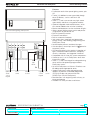
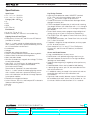
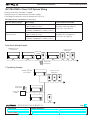
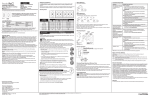
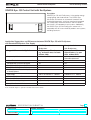
Control Unit with EcoSystem®
Preset Dimming Controls
369310 Rev. B 1 11.17.11
GRAFIK Eye® QS Control Unit with EcoSystem®
Open
1
Preset
2
Close
3
4
Off
Description
GRAFIK Eye® QS with EcoSystem® is the premier energysaving lighting and shade control. The GRAFIK Eye®
QS control unit features an astronomic timeclock and
intuitive lighting presets, which are seamlessly integrated
with EcoSystem® fluorescent ballasts and LED drivers,
and Lutron’s QS components and systems. Additionally,
the GRAFIK Eye® QS with EcoSystem® control unit is
compatible with all Lutron wired QS products and systems,
including Quantum®.
LUTRON
Application Suggestions and Differences between GRAFIK Eye® QS with EcoSystem®
and Standard EcoSystem® Bus Supply
GRAFIK Eye® QS with
EcoSystem®
Energi Savr NodeTM
with EcoSystem®
Suggested/Recommended Applications
Single rooms, partitioned spaces,
e.g., conference room, classroom,
ballroom, lobby
Open spaces, multiple
enclosed rooms, e.g., open
office, window offices
Programming Method
Info Screen on the QS control unit
Via Energi Savr NodeTM App for
iPod mobile digital device
Integral Timeclock
Yes
No
Compatible with seeTouch® QS Keypads
Yes
Yes
Compatible with EcoSystem® Wall Controls
No
Yes
Compatible with EcoSystem® IR Sensors
No
Yes
Includes dry contact closure for integration to BMS
or Security Systems
Yes
Yes
Input Voltage
120-127 or 220-240 V
Number of EcoSystem® Busses
1
1 or 2
Number of Zones
6, 8, or 16
Programmable
Number of Line-Voltage Outputs
3 (Zones 1-3 only)
--
Compatible with other QS Devices
Yes
Yes
50/60 Hz
120/240/277 V
50/60 Hz
iPod is a trademark of Apple Inc., registered in the United States and other countries.
®
SPECIFICATION SUBMIT T A L
Job Name:
Job Number:
Model Numbers:
Page 1
Control Unit with EcoSystem®
Preset Dimming Controls
369310 Rev. B 2 11.17.11
Mechanical Dimensions
94 in
(239 mm)
4 in
(10 mm)
2 in
(51 mm)
4$ in
(119 mm)
Front View
Side View
Fits into a 4-gang U.S. backbox, 3` in (89 mm) deep; Lutron P/N 241-400
System Topology
Example of Wired System
Wired QS link
GRAFIK Eye® QS
wireless
GRAFIK Eye® QS
wireless
LUTRON
Quantum®
(optional)
LUTRON
seeTouch® QS
EcoSystem®
ballast
®
LUTRON
seeTouch®
QS
QSE-CI-NWK-E
Wired
occupancy
sensor
Job Number:
LUTRON
QS Sensor
Module
Energi Savr
NodeTM
SPECIFICATION SUBMIT T A L
Job Name:
Sivoia® QS
shade
Page 2
Model Numbers:
LUTRON
LUTRON
Control Unit with EcoSystem®
Preset Dimming Controls
369310 Rev. B 3 11.17.11
Open
1
Preset
2
Close
3
4
Off
LUTRON
Note: General Engraving (-EGN) shown.
1
2
3
4
5
6
OK
Open
1
Preset
2
Close
3
4
Off
USB
type
mini B
Optional
shade
control
keypad
Zone
control
®
Infrared
receiver
Lighting
control
keypad
SPECIFICATION SUBMIT T A L
Job Name:
Job Number:
Model Numbers:
Info
screen
Features
• Pushbutton recall of four preset lighting scenes, plus
Off.
• Twelve (12) additional scenes accessible through
other QS devices, such as seeTouch® QS
wallstations.
• Zones 1, 2, and 3 can control many light source
types directly and others using power modules.
• Optional integrated shade control buttons, which
can also be added to the unit after installation.
• Master override buttons to raise and lower all lights.
• Allows setup of lighting scenes and shade presets
using buttons on the control unit.
• Built-in infrared (IR) receiver.
• External IR connection.
• Built-in astronomic timeclock.
• Info screen shows zone light level percentage,
energy savings, zone labeling, programming, and
EcoSystem® setup.
• Lockout option prevents accidental changes.
• One occupancy sensor input and 24 V power for
occupancy sensor.
• QS communication link for seamless integration of
lights, motorized window treatments, occupancy
sensors, wallstations, and integration interfaces.
• Compatible with all Lutron QS system components.
• Control up to 6, 8, or 16 EcoSystem® zones from
internal bus supply.
• Zones 1, 2, and 3 are integral line voltage dimming
zones and can be optionally programmed as
EcoSystem® zones.
• Up to 64 EcoSystem® or Hi-lume® 3D ballasts can
be addressed and grouped to zones.
• Integral EcoSystem® setup and programming
replaces the need for a handheld programmer
(C-PDA-CLR does not communicate with
GRAFIK Eye® QS with EcoSystem®)
• Backlit buttons with engraving make unit easy to
locate and operate.
• Available in a variety of colors and finishes.
Page 3
Control Unit with EcoSystem®
Preset Dimming Controls
369310 Rev. B 4 11.17.11
Specifications
Input Power
• 120 - 127 V
• 220 - 240 V
50/60 Hz
50/60 Hz
Listings (120 - 127 V
• UL
• CSA
• NOM
• CEC (Title 24)
)
Environment
• 32 to 104 °F (0 to 40 °C).
• Relative humidity less than 90% non-condensing.
Lighting Sources/Load Types
• EcoSystem®, Hi-lume® 3D, and Hi-lume® LED ballasts
(available on all zones).
Zones 1, 2, and 3 control the following lighting sources
with a smooth, continuous square law dimming curve or
on a full conduction non-dim basis:
• Incandescent
• Halogen
• Magnetic low-voltage transformer
• Lutron Tu-Wire® electronic fluorescent dimming ballast
• Advance Mark X® electronic dimming ballast
• Neon and cold cathode
• Non-dim (incandescent, magnetic low-voltage, Tu-Wire®,
or neon/cold cathode)
• Cree LR4/6, 120 V
fixtures (for loading capacities,
please refer to the LED report card located at
www.lutron.com/LEDtool)
Please refer to “Capacities” for more information.
Zones 1, 2, and 3 control the following lighting sources
with a smooth, continuous square law dimming curve
or on a full conduction non-dim basis through separate
Lutron power modules:
• Electronic low-voltage transformer
• Lutron Hi-lume®, Eco-10®, and Compact SETM electronic
fluorescent dimming ballast
• Non-dim
• 0 - 10 V
®
SPECIFICATION SUBMIT T A L
Job Name:
Job Number:
Model Numbers:
Key Design Features
• Lightning strike protection meets ANSI/IEEE standard
62.41-1980. Can withstand voltage surges of up to
6000 V
and current surges of up to 3000 A.
• Tested to withstand 16 kV electrostatic discharge without
damage or memory loss.
• RTISSTM-equipped: Compensates in real time for incoming
line voltage variations (no visible flicker with +/-2% change in
RMS voltage per cycle, and +/-2% Hz change in frequency
per second).
• Power failure memory retains programming and light level
settings for up to 10 years in the event of a power loss.
• The GRAFIK Eye® QS supplies 3 Power Draw Units (PDUs)
on the QS link.
For complete information, see “Power Draw Units on the QS
Link,” Lutron PN 369405
• Faceplate is hinged at the top and bottom, and stays open
at 180° for ease of access.
• Direct control of 120 V
and 277 V
EcoSystem®,
Hi-lume® 3D, and Hi-lume® LED ballasts (no interface
required).
Scene and Shade Buttons
• Large, rounded buttons are easy to use.
• Backlit buttons with optional engraving make it easy to
find and to operate the control unit in low light conditions
(backlight can be disabled).
• Optional button engraving is angled up to the eye for easy
reading.
• Predefined label stickers are included for field labeling.
• 4 preset lighting scenes, plus Off, are accessible from the
front of the control unit.
• 12 additional scenes are stored in the control unit and are
accessible from seeTouch® QS wallstations and
QS interfaces.
• Light levels fade smoothly between scenes. Fade time can
be set differently for each scene: 0 to 59 seconds, or 1 to
60 minutes. Maximum fade time from Off is 3 seconds.
Page 4
Control Unit with EcoSystem®
Preset Dimming Controls
369310 Rev. B 5 11.17.11
Specifications
Shade Control
• The GRAFIK Eye® QS control unit can include up to 3
shade button columns. Each column has backlit open,
preset, close, and raise/lower buttons.
• Each shade button column can be programmed to
operate one shade or a group of shades. (Shades may
be assigned to more than one shade button column).
• Faceplates are available with 1, 2 and 3 shade button
columns.
Zone Control
• Each zone has a dedicated raise and lower button to
adjust the zone.
• Each zone has a dedicated 7 LED bar graph for level
status. Percentage of light level and energy saved is
displayed on the info screen.
• All zone information has blue backlit LEDs. Backlight
turns off when idle for 30 seconds.
Info Screen
• OLED (organic LED) screen is viewable from all angles.
• Screen turns off when idle for 30 seconds.
• Programmable zone labels.
• Programmable scene labels.
• Status of real-time zone percentage and energy savings.
• Programmable timeclock schedules.
• Programmable shade labels.
Astronomic Timeclock
• Integral to all units.
• 7 daily schedules available.
• One available holiday schedule is programmable by date up
to one year in advance.
• 25 events per day maximum.
• Timeclock events are programmable to control scenes
that affect any Energi Savr NodeTM QS unit connected
on the QS link without changing the local scene on the
GRAFIK Eye® QS control unit.
• Astronomic times are programmable by integral city
database or by entering latitude and longitude. Times
automatically adjust throughout the year based on location.
• Automatically adjusts for Daylight Saving Time (DST),
adjusted for the new dates; DST is programmable.
• Local timeclock events can activate any of the following
features:
- Scenes 1 to 16 and Off
- Any available shade presets
- Start and End afterhours mode
- Enable and Disable daylighting for all zones/groups
- Enable and Disable occupancy for occupancy/vacancy
sensors
- Enable and Disable occupied events for all occupancy
sensors
System Communications and Capacities
• Low-voltage type IEC PELV/NEC® Class 2 wiring connects
control units, wallstations, motorized shades, and control
interfaces.
• A QS system can have up to 100 devices and 100 zones.
• Class 1/Class 2 wiring connects ballast to control unit.
Infrared
• Infrared (IR) receiver allows infrared transmitters to select 8
scenes, raise/lower lighting zones, or raise/lower shades.
• Transmitter buttons imitate buttons on faceplate.
• 50 ft (15 m) line of sight range.
• Terminal block infrared input for connection to a wired
IR input from third-party equipment.
• IR can be disabled via programming.
• Works with Lutron GRX-IT and GRX-8IT infrared remote
controls.
®
SPECIFICATION SUBMIT T A L
Job Name:
Job Number:
Model Numbers:
Page 5
Control Unit with EcoSystem®
Preset Dimming Controls
369310 Rev. B 6 11.17.11
Specifications
Accessory Controls: seeTouch® QS Wallstations
(QSWS2)
• Wired seeTouch® QS keypads provide the following
features:
- Access to one or more of the 16 scenes on the
GRAFIK Eye® QS control unit
- Zone toggle, partitioning, sequencing, fine tune, panic
mode, and timeclock enable/disable
- Contact closure inputs
- Various other functions that are available on specific
wallstation configurations. Refer to the seeTouch
specification submittal.
Accessory Controls:
DMX Output Interface (QSE-CI-DMX)
• Any zone on the GRAFIK Eye® QS control unit can be
mapped to any single DMX512 Channel.
• Any zone on the GRAFIK Eye® QS control unit can be
simultaneously mapped to any three DMX512 channels
(providing RGB/CMY control).
• DMX loads cannot be used with daylighting. Accessory Controls: QS Sensor Module (QSM2)
• The QS Sensor Module provides a means to link
wired or wireless occupancy and daylight sensors to a
GRAFIK Eye® QS control unit via the wired QS link.
- Occupancy sensors wired (or wirelessly linked) to
a QS Sensor Module can be used by one or more
GRAFIK Eye® QS control units on the wired link.
- Daylight sensors wired (or wirelessly linked) to a
QS Sensor Module can be used by one or more
GRAFIK Eye® QS control units on the wired link.
- Infrared sensors can control either one or more zones
or scenes on the GRAFIK Eye® QS control unit.
Functionality varies; refer to the documentation for the
QS Sensor Module for details.
- Pico® wireless controls wirelessly linked to a QS Sensor
Module can be used to control one or more zones or
scenes on the GRAFIK Eye® QS control unit.
Accessory Controls: QS Keyswitch Wallstations
(QSWS2-KS)
• Recalls preset light levels for any two scenes including
Off.
• Allows fine-tuning (raise/lower level) of a zone or group of
zones.
• Starts/Stops scene sequencing (Scenes 1-4 or Scenes
5-16)
• Enables/Disables Timeclock
• Enables/Disables occupancy sensors
• Enables/Disabled daylight sensors
• Allows toggle of Zone(s) to a preset level and off.
• Enables/Disables panic mode.
• Starts/Stops afterhours mode.
Accessory Controls: Contact Closure Input/Output
Interface (QSE-IO)
• Recalls preset light levels for the following set of scenes
on the GRAFIK Eye® QS control unit:
Scenes 1-4 and Off Scenes 9-12 and Off
Scenes 5-8 and Off Scenes 13-16 and Off
• Sequence scenes 5-16, Enable/Disable Zone Lockout,
Enable/Disable Scene Lockout, Enable/Disable Panic
Mode, Enable/Disable Timeclock.
• Occupancy Sensors. An individual input counts as 1
occupancy sensor for the GRAFIK Eye® QS control unit.
Each input can be assigned to either Scene Control or
Zone Control (please refer to the Occupancy Sensor(s)
section of this guide).
• Zone Toggle. Allows an input to toggle one or more zones
to a preset level and off.
• Shade Output mode. A Shade Column on the
GRAFIK Eye® QS control unit can be linked to control
outputs 1-3 and/or outputs 4-5 on the QSE-IO.
®
SPECIFICATION SUBMIT T A L
Job Name:
Job Number:
Model Numbers:
Accessory Controls: Ethernet and RS232 Interface
(QSE-CI-NWK-E)
• Allows for monitoring and control of the outputs and local
scenes of the GRAFIK Eye® QS control unit.
Other Accessory Controls and Devices
• Energi Savr NodeTM QS (ESN). See the SPecification
SUbmittal for complete details.
Occupancy Sensor(s)
• The GRAFIK Eye® QS control unit works with occupancy
sensors through either:
- Scene Control: Up to four sensors activate userselectable occupancy and vacancy scenes.
- Zone Control: Up to four sensors per zone activate userselected occupancy and vacancy zone levels.
• Occupancy sensors may include:
- Contact closure sensors wired to CCI input on back of
GRAFIK Eye® QS control unit
- Wired or wireless sensors connected QS Sensor Module
(QSM)
• If any sensor in a group detects occupancy, then the
GRAFIK Eye® QS control unit will go to the designated
occupancy scene or zone level.
• If all sensors in a group detect vacancy, then the
GRAFIK Eye® QS control unit will go to the designated
vacancy scene or zone level. Page 6
Control Unit with EcoSystem®
Preset Dimming Controls
369310 Rev. B 7 11.17.11
Specifications
Daylight Sensor(s)
• The GRAFIK Eye® QS with EcoSystem® control unit works
with compatible daylight sensors to adjust electric light
levels based on measured daylight levels. Sensors can
be configured to control either GRAFIK Eye® QS zones or
groups of EcoSystem® loads independent of zoning.
• Daylight sensors may include:
- Wired sensors connected to EcoSystem® ballasts or
interfaces
- Wired or wireless sensors connected to a QS sensor
module (QSM)
• In Zone Mode, a daylight sensor can control one or more
GRAFIK Eye® QS zones. Each zone can be calibrated to
target light levels.
- A zone can be controlled by no more than one daylight
sensor
• In Group Mode, a daylight sensor can control one or
more EcoSystem® loads, regardless of how they are
zoned on the GRAFIK Eye® QS control unit.
- A group can be controlled by a single daylight sensor
- Each group can be calibrated to independent target light
levels
- Up to 16 groups are available
• Daylight control can be enabled or disabled on a sceneby-scene basis
- By default, daylight control is enabled in all scenes
Note: Daylight control through the GRAFIK Eye® QS
control unit only affects lighting loads. Shade groups
cannot be controlled by daylight sensors. Daylighting
does not affect DMX or RGB/CMY DMX loads.
Contact Closure Input (CCI) with Power Supply Output
• Each GRAFIK Eye® QS control unit has one contact closure
input (Terminal A).
- The attached device must provide a dry contact closure
or solid-state output.
- Input is miswire-protected up to 36 V .
• The contact closure is capable of accepting the following
types of inputs:
- Maintained (default): The GRAFIK Eye® QS control unit will
act on both a contact closure and a contact open/release
event.
- Momentary: The GRAFIK Eye® QS control unit will act on
only contact closure events.
• Each GRAFIK Eye® QS control unit can supply 50
mA maximum at 24 V .
- Useful for powering occupancy sensors.
- An auxiliary power supply must be used if the device
requires more than 50 mA.
• The CCI is capable of operating in the following modes
- Occupancy: If an occupancy sensor is wired directly to
the GRAFIK Eye® QS control unit.
- Emergency: This setting allows the GRAFIK Eye® QS
control unit to work with a LUT-ELI. When an emergency
situation is detected, all lights will go to full on, and no
operations will be allowed until the emergency signal is
cleared.
- Afterhours: Allows the CCI to start and end the afterhours
mode.
- Timeclock: Allows the CCI to enable and disable the
timeclock.
- Scene Lockout: Prevents the user from making any
changes to the control unit. The current scene will stay on
until the CCI enables normal operation.
- Save Never: Prevents any changes from being saved
while the CCI is being used.
- Disable CCI: The CCI will have no effect on the system
and will not appear on the list of available sensors.
Security Lockout Password
• A 4-digit password (using characters A to Z and 0 to
9) can be enabled/disabled to lock out access to the
Programming Menu.
• By default there is no password enabled on the GRAFIK
Eye® QS control unit.
• If case the 4-digit password is forgotten, contact Lutron
Technical Support to regain access.
®
SPECIFICATION SUBMIT T A L
Job Name:
Job Number:
Model Numbers:
Page 7
Control Unit with EcoSystem®
Preset Dimming Controls
369310 Rev. B 8 11.17.11
Capacities
220 - 240 V
Unit Capacity (watts)
MLV
Zone Capacity (watts)
MLV
50 / 60 Hz
120 - 127 V
50 / 60 Hz
3000
2000
3000 VA / 2400 W
2000 VA / 1600 W
40 – 1200
25 – 800
40 – 1200 VA / 40 – 960 W
25 – 800 VA / 25 – 600 W
®
Load Type Notes (Zones 1, 2 and 3)
• All electronic low-voltage (ELV) lighting used with an interface must be rated for reverse phase control dimming. Before
installing an ELV light source, verify with the manufacturer that their transformer can be dimmed. When dimming, an
ELV interface (such as the PHPM-PA-DV-WH) must be used with the control unit.
• Not all zones must be connected; however, connected zones must have a minimum load as specified above.
• Maximum total lighting load for a magnetic low-voltage (MLV) varies by input voltage:
- 120 - 127 V : 800 VA / 600 W
- 220 - 240 V : 1200 VA / 960 W
• Maximum total lighting load for Lutron Tu-Wire® and Advance Mark X® electronic dimming ballasts (120 to 127 V
only) must not exceed 6 A per zone or 16 A per unit.
• No zone may be loaded with more than the capacity specified above. For higher wattage applications, or for 277 V
applications, use Lutron power module PHPM-PA, PHPM-WBX, PHPM-PA-DV, PHPM-SW, or PHPM-WBX-DV.
• For controlling low-wattage loads (CFL, LED) in a non-dim application, contact Lutron Technical Support for the
appropriate solution.
System Limits
• The QS wired communication link is limited to 100 devices or 100 zones.
®
SPECIFICATION SUBMIT T A L
Job Name:
Job Number:
Model Numbers:
Page 8
Control Unit with EcoSystem®
Preset Dimming Controls
369310 Rev. B 9 11.17.11
GRAFIK Eye® QS with EcoSystem® Control Unit
Custom Color Options and Model Numbers
You must order a Base Unit and a Faceplate Kit
See Standard Color Combinations page for faceplate, stripe, and button colors
Base Unit
Example:
QSGR - _ E
QSGR-6E
6-zone base unit
and
QSGFP-2IV-EGN
Ivory faceplate kit with two
shade columns and general
engraving
EcoSystem®
Prefix
Number
of Zones
6 = 6 zones
8 = 8 zones
16 = 16 zones
Faceplate Kit
(includes coordinating stripe and buttons)
QSGFP
Faceplate
Prefix
-
-
Number
of Shade
Columns
Omit = none
1 = 1 column
2 = 2 columns
3 = 3 columns
1 9
Color/
Finish
Top
Door
Color
Keypad
Engraving
Code
Omit = s ame as
unit
T = Translucent
2 10
3 11
4 12
5 13
6 14
7 15
1 9
8 16
Faceplate Custom Color/Finish Codes
Architectural Matte
Finishes
Standard
(ship in 48 hours)
White
Ivory
Beige
Gray
Brown Black
Almond
Light Almond
WH
IV
BE
GR
BR
BL
AL
LA
Architectural Metal
Finishes
Bright Brass
Bright Chrome
Bright Nickel
Satin Brass
Satin Chrome
Satin Nickel
Antique Brass
Antique Bronze
Anodized Aluminum
Finishes
Clear
Black
Brass
®
BB
BC
BN
SB
SC
SN
QB
QZ
CLA
BLA
BRA
Satin Color Matte
Finishes
Snow
Biscuit
Eggshell
Taupe
Midnight
Limestone
Stone
Desert Stone
Terracotta
Hot
Goldstone
Palladium
Plum
Turquoise
Bluestone
Sea Glass
Greenbriar
Sienna
Merlot
Mocha Stone
SPECIFICATION SUBMIT T A L
Job Name:
Job Number:
Model Numbers:
2 10
Keypad Engraving Codes
9-16
1-8
SW
BI
ES
TP
MN
LS
ST
DS
TC
HT
GS
PD
PL
TQ
BG
SG
GB
SI
MR
MS
3 11
4 12
5 13
Omit = U
nengraved
OK
Ships with engraving certificate that
customer can redeem at no charge
EGN = General Engraving
1
Open
2
Preset
3
Close
4
Off
Lighting
keypad
Shade
column
NST = N
on-Standard Text Engraving
Please visit the GRAFIK Eye® QS website
at www.lutron.com/grafikeyeqs
for custom engraving forms. Submit
completed form with order, and unit will
ship engraved as specified by customer.
Page 9
6 14
Control Unit with EcoSystem®
Preset Dimming Controls
369310 Rev. B 10 11.17.11
GRAFIK Eye® QS with EcoSystem® Control Unit
Custom Options and Model Numbers
See previous page for Custom Model Numbers
See Standard Color Combinations page for faceplate, stripe, and button colors
Custom Button Kit
QSGB - 5B - WH Custom Button
Kit Prefix
Button
Configuration
3BRL = 3
-button with
raise/lower
(shade column)
5B
=2 105-button
3 11
4 12
1 9
(lighting keypad)
5 13
Keypad
Engraving
Code
Button
Color/
Finish
6 14
7 15
1 9
8 16
9-16
1-8
Button Kit Custom
Color/Finish Codes
Architectural Matte
Finishes
White
Ivory
Beige
Gray
Brown Black
Almond
Light Almond
WH
IV
BE
GR
BR
BL
AL
LA
3 11
4 12
5 13
6 14
7 15
8 16
Omit = U
nengraved
OK
Ships with engraving certificate that
customer can redeem at no charge
EGN = General Engraving
Satin Color Matte
Finishes
Snow
Biscuit
Eggshell
Taupe
2 10
Keypad Engraving Codes
SW
BI
ES
TP
1
Open
2
Preset
3
Close
9-1
1-8
4
Off
Lighting
keypad
Shade
column
NST = N
on-Standard Text Engraving
Please visit the GRAFIK Eye® QS website
at www.lutron.com/grafikeyeqs
for custom engraving forms. Submit
completed form with order, and unit will
ship engraved as specified by customer.
Custom Stripe Kit
QSGS - WH
Stripe Color/
Finish
Stripe
Kit
Prefix
Stripe Custom Color/Finish Codes
Same as Faceplate colors on previous page
®
SPECIFICATION SUBMIT T A L
Job Name:
Job Number:
Model Numbers:
Page 10
Control Unit with EcoSystem®
Preset Dimming Controls
369310 Rev. B 11 11.17.11
GRAFIK Eye® QS with EcoSystem® Control Unit
Standard Color Combinations
See previous pages for Custom Model Numbers
F (faceplate)
S (stripe)
Open
1
Preset
2
Close
3
4
Off
LUTRON
Suffix Faceplate (F)
Architectural Matte
WH
White
IV
Ivory
BE
Beige
GR
Gray
BR
Brown
BL
Black
AL
Almond
LA
Light Almond
Architectural Metal
BB
Bright Brass
BC
Bright Chrome
BN
Bright Nickel
SB
Satin Brass
SC
Satin Chrome
SN
Satin Nickel
QB
Antique Brass
QZ
Antique Bronze
Anodized
CLA
Clear
BLA
Black
BRA
Brass
®
Stripe (S)
Button (B)
Job Number:
F (faceplate)
Example:
If you order QSGR-6E-1WH, your GRAFIK
Eye® QS control unit with 6 lighting zones
and 1 shade column will come with a white
faceplate (both top and bottom), gray stripe,
and white buttons.
Suffix Faceplate (F)
Satin Matte
Gray
White
MN
Midnight
Beige
Ivory
TP
Taupe
Ivory
Beige
SW
Snow
Black
Gray
ES
Eggshell
Black
Brown
BI
Biscuit
Gray
Black
LS
Limestone
Light Almond Almond
ST
Stone
Almond
Light Almond DS
Desert Stone
TC
Terracotta
Black
Black
BG
Bluestone
Black
Black
HT
Hot
Black
Black
MR
Merlot
Black
Black
SI
Sienna
Black
Black
GB
Greenbriar
Black
Black
SG
Sea Glass
Black
Black
MS
Mocha Stone
Black
Black
GS
Goldstone
PD
Palladium
Black
Black
PL
Plum
Black
Black
TQ
Turquoise
Black
Black
SPECIFICATION SUBMIT T A L
Job Name:
B (buttons)
Faceplate is comprised of a top and bottom.
The bottom will always be the color indicated
under “faceplate.” The top may be the
same color or translucent. Use the chart for
faceplates that have the same color top and
bottom. If a translucent lid is chosen, the
stripe will automatically be the same color as
the bottom lid.
Model Numbers:
Stripe (S)
Button (B)
Gray
Gray
Gray
Beige
Eggshell
Gray
Gray
Taupe
Taupe
Gray
Taupe
Taupe
Brown
Gray
Gray
Taupe
Ivory
Gray
Taupe
Gray
Black
Taupe
Snow
Eggshell
Biscuit
Gray
Gray
Taupe
Taupe
Gray
Taupe
Taupe
Brown
Gray
Gray
Taupe
Ivory
Gray
Taupe
Gray
Page 11
Control Unit with EcoSystem®
Preset Dimming Controls
369310 Rev. B 12 11.17.11
Overview
Terminations
Load wiring
EcoSystem® bus (E1, E2)
Communication link
Occupancy sensor/contact closure input
and 24 V power
IR input
Power wiring
Wire Gauge
12 AWG (4.0 mm2)
14 AWG (2.5 mm2)
16 AWG (1.5 mm2)
18 AWG (1.0 mm2)
®
Maximum EcoSystem®
Bus Length
2200 ft (671 m)
1400 ft (427 m)
900 ft (275 m)
570 ft (175 m)
SPECIFICATION SUBMIT T A L
Job Name:
Job Number:
Model Numbers:
Page 12
Control Unit with EcoSystem®
Preset Dimming Controls
369310 Rev. B 13 11.17.11
Power Group Wiring Example
On the QS link, there are devices that supply power and devices that consume power. Each device has a specific
number of Power Draw Units (PDUs) it either supplies or consumes. A Power Group consists of one device that
supplies power and one or more devices that consume power; each Power Group may have only one power-supplying
device. Refer to the QS Link Power Draw Units specification submittal (Lutron PN 369405) for more information
concerning PDUs.
Within Power Groups on the QS link, connect all 4 terminals (1, 2, 3, and 4), shown by the letter A in the diagram.
Between devices on the QS link that supply power, connect only terminals 1, 3, and 4 (NOT terminal 2), shown by the
letter B on the diagram.
Wiring can be T-tapped or daisy-chained.
A
Power Group 1
LUTRON
GRAFIK Eye® QS
control unit
Supplies PDUs
A
LUTRON
B
Control Interfaces
Consume PDUs
(Do not connect
terminal 2: 24 V )
Wallstations
Consume PDUs
Power Group 2
A
Connect all 4
terminals within a
power group:
1: Common
2: 24 V
3 and 4: Data
B
LUTRON
Energi Savr NodeTM QS
unit Supplies PDUs
LUTRON
Connect only 3
terminals between
power groups:
1: Common
3 and 4: Data
Do not connect
Terminal 2: 24 V
LUTRON
Wallstations
Consume PDUs
B
(Do not connect
terminal 2: 24 V
)
Power Group 3
A
Wireless Occupancy Sensor
does not consume PDUs
QS Power Supply
Supplies PDUs
LUTRON
Control Interfaces
Consume PDUs
Wallstations
Consume PDUs
B
(Do not connect
terminal 2: 24 V )
®
Quantum® panel
Supplies PDUs
SPECIFICATION SUBMIT T A L
Job Name:
Job Number:
QS Sensor Module with
wired Occupancy Sensor
Consumes PDUs
Model Numbers:
Page 13
Control Unit with EcoSystem®
Preset Dimming Controls
369310 Rev. B 14 11.17.11
Line Voltage Wiring
}
Do not use
Rear of
GRAFIK Eye® QS
control unit
To Load 1
Line voltage (hot/live)
is labeled L.
To Load 2
To Load 3
Loads 1, 2, 3
120-127 V
or
220-240 V
1 2 3 4 5 6 L N
120-127 V
or
220-240 V
Distribution Panel
• Pull power wiring from distribution panel and to light fixtures.
• Each line voltage terminal can accept one 12 AWG (2.5 mm2) wire.
• Consult Lutron for non-dim relay wiring and/or load side emergency transfer wiring.
®
SPECIFICATION SUBMIT T A L
Job Name:
Job Number:
Model Numbers:
Page 14
3
2
1
4
4
Control Unit 3with EcoSystem®
3
2
2
1
Preset Dimming Controls
1
369310 Rev. B 15 11.17.11
EcoSystem® Bus Wiring
4
3
2
1
4
3
EcoSystem® Bus Link Terminal Detail
2
1
1 2 3 4 5 6 L N
4
3
2
1
E2
E1
EcoSystem®
ballasts
E2
E1
To additional EcoSystem®
ballasts
EcoSystem® Bus Wiring Example
To additional ballasts and
modules (up to 64 total)
EcoSystem® Bus
EcoSystem®
Ballast
LUTRON
GRAFIK Eye® QS
with EcoSystem®
(limit one per
EcoSystem® link)
®
EcoSystem®
Module
Occupancy
Sensor
SPECIFICATION SUBMIT T A L
Job Name:
Job Number:
Model Numbers:
Eco-10® or
Hi-Lume®
Ballast
EcoSystem®
Ballast
EcoSystem®
Ballast
Daylight Sensor
Page 15
Control Unit with EcoSystem®
Preset Dimming Controls
369310 Rev. B 16 11.17.11
IEC PELV/NEC® Class 2 QS System Wiring
• Wiring can be daisy-chained or T-tapped.
• Wiring must be run separately from line/mains voltage.
• Total length of control link must not exceed 2000 ft (610 m).
Wire Sizes (check compatibility in your area)
QS Link Wiring Length
Wire Gauge
Lutron Cable Part Number
Less than 500 ft (153 m)
Power (terminals 1 and 2)
1 pair 18 AWG (1.0 mm2)
GRX-CBL-346S (non-plenum)
GRX-PCBL-346S (plenum)
Data (terminals 3 and 4)
1 twisted, shielded pair 22 AWG (0.5 mm2)
500 to 2000 ft
(153 to 610 m)
Power (terminals 1 and 2)
1 pair 12 AWG (4.0 mm2)
GRX-CBL-46L (non-plenum)
GRX-PCBL-46L (plenum)
Data (terminals 3 and 4)
1 twisted, shielded pair 22 AWG (0.5 mm2)
Daisy-Chain Wiring Example
GRAFIK Eye® QS
Control Unit
seeTouch® QS
wallstations
Sivoia® QS
Shade
LUTRON
LUTRON
LUTRON
LUTRON
LUTRON
Sivoia® QS
smart panel
LUTRON
LUTRON
LUTRON
LUTRON
LUTRON
LUTRON
LUTRON
LUTRON
LUTRON
T-Tap Wiring Example
GRAFIK Eye® QS
Control Unit
seeTouch® QS
wallstations
LUTRON
LUTRON
LUTRON
LUTRON
LUTRON
LUTRON
Sivoia® QS
smart panel
Sivoia® QS
Shade
LUTRON
LUTRON
LUTRON
LUTRON
LUTRON
LUTRON
LUTRON
LUTRON
®
SPECIFICATION SUBMIT T A L
Job Name:
Job Number:
Model Numbers:
Page 16
Control Unit with EcoSystem®
Preset Dimming Controls
369310 Rev. B 17 11.17.11
Mounting
Standard 4-gang
U.S. wallbox,
3` in (89 mm) deep
(available from
Lutron, P/N 241-400)
Hinged
top lid
Mounting
screws (4)
GRAFIK Eye® QS
with EcoSystem®
control unit
Hinged
bottom lid
®
SPECIFICATION SUBMIT T A L
Job Name:
Job Number:
Model Numbers:
Page 17