1
BA_KM85_86_U_A4.book Seite 0 Dienstag, 20. Januar 2004 12:34 12
STIH)
STIHL KM 85
Instruction Manual
Manual de instrucciones
Warning!
For safe operation follow all safety
precautions in Instruction Manual - improper
use can cause serious injury.
Advertencia!
Para su seguridad durante el manejo de este
producto, siga siempre las precauciones de
seguridad dadas en el manual de
instrucciones - el uso indebido puede causar
lesiones graves.
english / USA
© 2002 Andreas Stihl AG & Co., Waiblingen
0458 462 8621. M3. K2. PM. Printed in USA
Printed on chlorine-free paper.
Printing inks contain vegetable oils;
paper can be recycled.
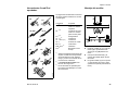
Contents
CombiSystem ................................... 2
Guide to Using this Manual .............. 3
Safety Precautions and
Working Techniques ......................... 4
Approved CombiTools .................... 11
Mounting the Bike Handle .............. 11
Adjusting the Throttle Cable ........... 13
Mounting the Loop Handle ............. 13
Fuel ................................................ 15
Fueling ............................................ 16
Starting / Stopping
the Engine ...................................... 17
Operating Instructions .................... 20
Cleaning the Air Filter ..................... 20
Spark Arresting Screen*
in Muffler ......................................... 21
Motor Management ........................ 21
Adjusting the Carburetor ................ 21
Checking the Spark Plug ................ 23
Replacing the Starter Rope
and Rewind Spring ......................... 24
Storing the Machine ........................ 27
Maintenance Chart ......................... 28
Main Parts and Controls ................. 29
Specifications ................................. 31
Special Accessories ....................... 32
Maintenance and Repairs ............... 32
STIHL Incorporated Federal
and California Emission Control
Warranty Statement ........................ 33
*
Allow only persons who understand the
manuals of the CombiEngine and the
CombiTool to operate your power tool.
To receive maximum performance and
satisfaction from your STIHL power tool,
it is important that you read and
understand the maintenance and safety
precautions, starting on page 4, before
using your power tool.
Contact your STIHL dealer or the STIHL
distributor for your area if you do not
understand any of the instructions in the
two manuals.
see “Guide to Using this Manual”
STIHl
KM 85, KM 85 R
1
english / USA
CombiSystem
!Warning!
The CombiEngine and CombiTool come
with separate instruction manuals.
Because this power tool is a high-speed
working tool, some special safety
precautions must be observed to reduce
the risk of personal injury. Careless or
improper use may cause serious or even
fatal injury.
Always read and make sure you
understand both instruction manuals
before starting and using your machine.
Keep the manuals in a safe place for
later reference.
2
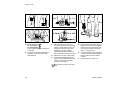
On brushcutters with a split boom
(T models), the CombiTool can be
used in place of any power tool
attachment.
..
..
+
002BA159 KN
STIHL's philosophy is to continually
improve all of its products. As a result,
engineering changes and improvements are made from time to time.
Therefore, STIHL cannot be responsible
for changes, modifications or
improvements not covered in this
manual. If the operating characteristics
or the appearance of your power tool
differs from those described in the two
manuals, please contact your STIHL
dealer for information and assistance.
+
In the STIHL CombiSystem™ a number
of different CombiEngines and
CombiTools can be combined to
produce a power tool. In this instruction
manual the functional unit formed by the
CombiEngine™ and CombiTool™ is
referred to as the power tool.
KM 85, KM 85 R
english / USA
Guide to Using this Manual
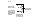
Pictograms
All the pictograms attached to the
machine are shown and explained in
this manual.
The operating and handling instructions
are supported by illustrations.
In addition to the operating instructions,
this manual may contain paragraphs
that require your special attention. Such
paragraphs are marked with the
symbols described below:
Symbols in text
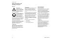
Warning where there is a risk of an
accident or personal injury or
serious damage to property.
The individual steps or procedures
described in the manual may be marked
in different ways:
Warning where there is a risk of
damaging the machine or individual
components.
:
Note or hint which is not essential
for using the machine, but may
improve the operator’s understanding of the situation and result
in better use of the machine.
Step or procedure without direct
reference to an illustration.
Description of step or procedure that
refers directly to the illustration and
contains item numbers that appear in
the illustration.
Example:
Loosen the screw (1)
Lever (2) ...
KM 85, KM 85 R
Note or hint on correct procedure in
order to avoid damage to the
environment.
Equipment and features
This instruction manual refers to
several models with different
features. Components that are not
installed in all models and related
applications are marked thus *.
Such components are available as
special accessories from your
STIHL dealer.
Engineering improvements
STIHL’s philosophy is to continually
improve all of its products. As a result,
engineering changes and improvements
are made from time to time. If the
operating characteristics or the
appearance of your machine differ from
those described in this manual, please
contact your STIHL dealer for
assistance.
Therefore, we cannot be responsible for
changes, modifications or
improvements not covered in this
manual.
3
english / USA
Safety Precautions and
Working Techniques
Warning!
Because this
CombiEngine is the
engine for a high-speed,
power tool, special safety
precautions must be
observed to reduce the
risk of personal injury.
It is important that you
read, fully understand and
observe the following
safety precautions and
warnings. Read the
owner's manuals and the
safety instructions of your CombiEngine
and CombiTool periodically. Careless or
improper use of any power tool may
cause serious or fatal injury.
Have your STIHL dealer show you how
to operate your power tool. Observe all
applicable local safety regulations,
standards and ordinances.
!Warning!
Do not lend or rent your power tool
without the owner's manuals. Be sure
that anyone using your power tool
understands the information contained
in these manuals.
4
!Warning!
THE OPERATOR!
Minors should never be allowed to use a
power tool. Bystanders, especially
children, and animals should not be
allowed in the area where a power tool is
in use.
Physical Condition
Never let the power tool run unattended.
Most of these safety precautions and
warnings apply to the use of all STIHL
power tools. Different models may have
different parts and controls. See the
appropriate section of your owner's
manual for a description of the controls
and function of the parts of your power
tool model.
Safe use of a power tool involves
1.
the operator
2.
the power tool
3.
the use of the power tool.
You must be in good physical condition
and mental health and not under the
influence of any substance (drugs,
alcohol, etc.) which might impair vision,
dexterity or judgement. Do not operate a
power tool when you are fatigued.
Be alert - if you get tired while operating
your power tool, take a break. Tiredness
may result in loss of control. Working
with any power tool can be strenuous. If
you have any condition that might be
aggravated by strenuous work, check
with your doctor before operating a
power tool.
!Warning!
The ignition system of the STIHL unit
produces an electromagnetic field of a
very low intensity. This field may
interfere with some pacemakers. To
reduce the risk of serious or fatal injury,
persons with a pacemaker should
consult their physician and the
pacemaker manufacturer before
operating this tool.
KM 85, KM 85 R
english / USA
Proper Clothing
THE POWER TOOL
!Warning!
For illustrations and definitions of the
power tool parts see the chapter on
"Parts and Controls".
To reduce the risk of injury, the operator
should wear proper protective apparel.
!Warning!
To reduce the risk of injury
to your eyes never
operate a power tool
unless wearing goggles or
properly fitted safety
glasses with adequate top
and side protection complying with ANSI
Z 87.1 (or your applicable national
standard).
!Warning!
CombiEngine noise may
damage your hearing.
Wear sound barriers (ear
plugs or ear mufflers) to
protect your hearing.
Continual and regular
users should have their hearing checked
regularly.
For further instructions on proper
clothing see the Safety Instructions in
the owner’s manual of the CombiTool.
KM 85, KM 85 R
!Warning!
Never modify a power tool in any way.
Only CombiTools supplied by STIHL or
expressly approved by STIHL for use
with the specific STIHL CombiEngine
models are authorized. Although certain
unauthorized attachments may be
useable on the STIHL CombiEngine,
their use may, in fact, be extremely
dangerous.
Preparation for the use of the power
tool
Always check your power tool for proper
condition and operation before starting,
particularly the throttle trigger, throttle
trigger interlock (if applicable), stop
switch, working tool, deflector and
harness.
The throttle trigger must move freely and
always spring back to the idle position.
The working tool must be properly
tightened and in safe operating
condition. Inspect for loose parts (nuts,
screws, etc.) and for cracked, bent,
warped or damaged working tools.
THE USE OF THE POWER TOOL
Transporting the power tool
!Warning!
Always turn off the engine and make
sure the working tool has stopped before
putting a power tool down. When
transporting your power tool in a vehicle,
properly secure it to prevent turnover,
fuel spillage and damage to the power
tool.
5
english / USA
Fueling
Your STIHL power tool uses an oilgasoline mixture for fuel (see the
chapter on „Fuel“ of your owner’s
manual).
!Warning!
Gasoline is an extremely
flammable fuel. If spilled
and ignited by a spark or
other ignition source, it
can cause fire and serious
burn injury or property
damage. Use extreme caution when
handling gasoline or fuel mix.
Do not smoke or bring any fire, flame,
spark or any other ignition source near
the fuel or power tool.
Fueling Instructions
!Warning!
Fuel your power tool in well-ventilated
areas, outdoors. Always shut off the
engine and allow it to cool before
refueling. Gasoline vapor pressure may
build up inside the fuel tank depending
on the fuel used, the weather conditions
and the tank venting system.
6
In order to reduce the risk of burns and
other personal injury from escaping gas
vapor and fumes, remove the fuel filler
cap on your power tool carefully so as to
allow any pressure build-up in the tank
to release slowly. Never remove fuel
filler cap while engine is running.
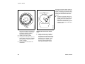
Cap with Grip
!Warning!
To do this with this STIHL
cap, raise the grip on the
top of the cap until it is
upright at a 90° angle.
Insert the cap in the fuel
tank opening with the
triangular marks on the grip of the cap
and on the fuel tank opening lining up.
Using the grip, turn the cap firmly
clockwise as far as it will go (approx. a
quarter turn).
To reduce the risk of fire or burn injury,
let the unit cool down before refueling
your power tool after use.
Select bare ground for fueling and move
at least 10 feet (3 m) from the fueling
spot before starting the engine. Wipe off
any spilled fuel before starting your
power tool and check for leakage.
!Warning!
Check for fuel leakage while refueling
and during operation. If fuel or oil
leakage is found, do not start or run the
engine until leak is fixed and spilled fuel
has been wiped away. Take care not to
get fuel on your clothing. If this happens,
change your clothing immediately.
Different models may be equipped with
different fuel caps.
!Warning!
In order to reduce the risk of fuel spillage
and fire from an improperly tightened
fuel cap, correctly position and tighten
the fuel cap in the fuel tank opening.
Fold the grip flush with the
top of the cap. If the grip
does not lie completely
flush with the cap and the
detent on the grip does
not fit in the
corresponding recess in the filler neck,
the cap is not properly seated and
tightened and you must repeat the
above steps.
KM 85, KM 85 R
english / USA
Screw Cap
!Warning!
Unit vibrations can cause
an improperly tightened
fuel filler cap to loosen or
come off and spill
quantities of fuel. In order
to reduce the risk of fuel
spillage and fire, tighten the fuel filler cap
by hand with as much force as possible.
Operating instructions
! Warning!
Improper use of any power tool can
cause serious or fatal personal injury. To
reduce the risk of personal injury to the
operator from operating the power tool
always follow the safety instructions on
operating the power tool as provided in
the owner’s manuals of the
CombiEngine and the CombiTool.
Starting
!Warning!
Your power tool is a one-person
machine. To reduce the risk of injury,
keep bystanders out of your working
area (see CombiTool manuals for
specific distances).
KM 85, KM 85 R
Stop the engine and cutting tool
immediately if you are approached. Start
and operate your power tool without
assistance. For specific starting
instructions, see the appropriate section
of your manuals. Place the power tool on
firm ground or other solid surface in an
open area. Maintain a good balance and
secure footing.
!Warning!
To reduce the risk of injury from loss of
control, be absolutely sure that the
working tool is clear of you and all other
obstructions and objects, including the
ground, because when the engine starts
at starting-throttle, engine speed will be
fast enough for the clutch to engage and
move the working tool.
!Warning!
When you pull the starter grip, don't
wrap the starter rope around your hand.
Do not allow the grip to snap back, but
guide the starter rope to rewind it
properly. Failure to follow this procedure
may result in injury to hand or fingers
and may damage the starter
mechanism.
See also the Safety Instructions on
Starting in the owner’s manual of the
CombiTool.
Muffler
!Warning!
Do not operate your power tool if the
muffler is damaged, missing or modified.
Such a muffler could cause an increase
in heat radiation or sparks, thereby
increasing the risk of fire or burn injury.
You may also permanent damage the
engine.
!Warning!
The muffler and other parts of the engine
(e.g. fins of the cylinder, spark plug)
become hot during operation and remain
hot for a while after stopping the engine.
To reduce risk of burns do not touch the
muffler and other parts while they are
hot.
!Warning!
To reduce the risk of fire or burn injury,
keep the area around the muffler clean.
Remove all debris such as pine needles,
branches or leaves when the engine is
off and cooled.
7
english / USA
Catalytic converter
!Warning!
Some STIHL power tool
models are equipped with
a catalytic converter,
which is designed to
reduce the exhaust
emissions of the engine
by a chemical process in the muffler.
Due to this process, the muffler does not
cool down as rapidly as conventional
mufflers when the engine returns to idle
or is shut off. To reduce the risk of fire
and burn injuries, the following specific
safety precautions must be observed.
!Warning!
Since a muffler with a catalytic converter
cools down less rapidly than conventional mufflers, never set your power tool
down where the muffler is near dry
brush, grass, wood chips or other
combustible materials while it is still hot.
Let the engine cool down sitting in the
upright position on concrete, metal, bare
ground or solid wood away from any
combustible substances.
8
!Warning!
!Warning!
An improperly mounted or damaged
cylinder housing or a damaged/
deformed muffler shell may interfere
with the cooling effect of the catalytic
converter. To reduce the risk of fire or
burn injury, do not continue working with
a damaged or improperly mounted
cylinder housing or a damaged/
deformed muffler shell. Your catalytic
converter is furnished with screens
designed to reduce the risk of fire from
the emission of hot particles. Due to the
heat from the catalytic reaction, these
screens will normally stay clean and
need no service or maintenance. If you
experience loss of performance and you
suspect a clogged screen, have your
muffler maintained by a STIHL Servicing
Dealer.
Your power tool produces
toxic exhaust fumes as
soon as the engine is
running. These gases
(e.g. carbon monoxide)
may be colorless and
odorless. To reduce the risk of serious or
fatal injury from inhaling toxic fumes,
never run the power tool indoors or in
poorly ventilated locations.
Working Conditions
Operate and start your power tool only
outdoors in a ventilated area.
Operate the power tool under good
visibility and daylight conditions only.
Work carefully.
!Warning!
Use of this product can generate dust
and fumes containing chemicals known
to cause respiratory disease, cancer,
birth defects, or other reproductive
harm. If you are unfamiliar with the risks
associated with the particular dust or
fume at issue, consult your employer,
governmental agencies such as OSHA
and NIOSH and other sources on
hazardous materials. The State of
California and some other authorities,
for instance, have published lists of
substances known to cause cancer,
reproductive toxicity, etc.
KM 85, KM 85 R
english / USA
Control dust and fumes at the source
where possible. In this regard use good
work practices and follow the
recommendations of OSHA/NIOSH and
occupational and trade associations.
When the inhalation of toxic dust and
fumes cannot be eliminated, the
operator and any bystanders should
always wear a respirator approved by
NIOSH/MSHA for the type of dust and /
or fumes encountered.
Important adjustments
!Warning!
To reduce the risk of personal injury from
loss of control or contact with the
running working tool, do not use a power
tool with incorrect idle adjustment. At
correct idle speed, the working tool
should not move. For directions on how
to adjust idle speed, see the appropriate
section of your owner's manual. If you
cannot set the correct idle speed, have
your STIHL dealer check your power
tool and make proper adjustments and
repairs.
KM 85, KM 85 R
MAINTENANCE, REPAIR AND
STORING
Maintenance, replacement, or repair
of the emission control devices and
systems may be performed by any
nonroad engine repair establishment
or individual. However, if you claim
warranty coverage for a component
which has not been serviced or
maintained properly or if
nonapproved replacement parts were
used, STIHL may deny warranty
coverage.
!Warning!
Use only identical STIHL replacement
parts for maintenance and repair. Use of
non-STIHL parts may increase the risk
of serious or fatal injury.
!Warning!
Always stop the engine and make sure
that the cutting tool is stopped before
doing any maintenance or repair work or
cleaning the power tool. Do not attempt
any maintenance or repair work not
described in your owner's manual. Have
such work performed at your STIHL
service shop only.
Wear gloves when handling or
performing maintenance on blade.
!Warning!
Never repair damaged cutting attachments by welding, straightening or
modifying the shape. This may cause
parts of the cutting tool to come off and
result in serious or fatal injuries.
Follow the maintenance and repair
instructions in the appropriate section of
your owner's manual. Please refer to the
maintenance chart on the last pages of
this manual.
9
english / USA
!Warning!
!Warning!
To reduce the risk of fire and burn
injuries, check the fuel filler cap for leaks
at regular intervals. Use the specified
spark plug and make sure it and the
ignition lead are always clean and in
good condition. Always press spark plug
boot snugly onto spark plug boot of the
proper size. (Note: If boot has
detachable SAE adapter nut, it must be
attached.) A loose connection between
spark plug boot and ignition wire
connector in the boot may create arcing
that could ignite combustible fumes and
cause a fire.
A damaged or improperly maintained
muffler will increase the risk of fire and
hearing loss. Never touch a hot muffler
or burn will result. If your muffler was
equipped with a spark-arresting screen
to reduce the risk of fire (e.g. in the USA,
Canada and Australia), never operate
your CombiEngine if the screen is
missing or damaged. Do not
disassemble, modify or remove any part
of the muffler or spark arresting screen.
Remember that the risk of forest fires is
greater in hot or dry weather. Have your
muffler serviced and repaired by your
STIHL Servicing Dealer only.
!Warning!
Never test the ignition system with
ignition wire boot removed from the
spark plug or with a removed spark plug,
since uncontained sparking may cause
a fire.
10
Additionally, the daily maintenance
schedule for your power tool set forth in
your STIHL Owner's Manual should be
strictly followed.
For any maintenance please refer to the
maintenance chart and to the warranty
statement near the end of this manual.
Store the power tool in a dry, high or
locked location out of reach of children.
Before storing for longer than a few
days, always empty the fuel tank. See
chapter “Storing the machine“.
Keep the cutting attachment sharp.
Tighten all nuts, bolts and screws,
except the carburetor adjustment
screws, after each use.
KM 85, KM 85 R
english / USA
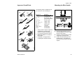
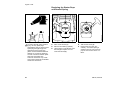
Approved CombiTools
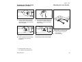
Mounting the Bike Handle
The following STIHL CombiTools may
be mounted on the CombiEngine:
CombiTool
FS 1)
FS
HL-0/90°
1)
BC
KW
KM 85, KM 85 R
Purpose
Brushcutter with
mowing head
Brushcutter with
grass cutting bladet
Power scythe
Hedge cutter
Hedge cutter
Pole pruner
Cultivator
Power edger
PowerSweep
Always observe chapter "Approved
Combinations of Cutting Tool,
Deflector, Handle and Harness" in
FS CombiTool instruction manual
5
1
4
3
A
2
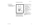
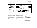
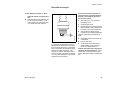
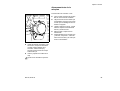
:
Mount the bike handle (1) on the
drive tube (2) about 16” (40 cm) (A)
forward of the engine.
2)
Barrier bar must be mounted on
loop handle
:
Place the clamp (3) and the handle
support (4) on the drive tube.
3)
Unsuitable or not approved for
CombiEngines with bike handle
:
Position the bike handle (1) on the
handle support - the rubber grip
must be on the left (viewed from the
engine)
932BA001 KN
FCS
FCB
1) 2)
FH 2) 3)
HL - 0° 3)
HL - 0/90° 2) 3)
HT 3)
BC 2) 3)
FCB, FCS 3)
KW 3)
HL-0°
FH
HT
6
6
FS
002BA128 KN
FS
11
english / USA
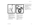
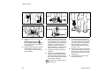
:
Place the clamp (5) on the handle
support.
:
Insert screws (6) in the holes and
clamp (3) and tighten them
moderately.
:
Line up the bike handle.
:
Tighten down the screws firmly.
13
11
10
9
7
14
12
14
8
13
14
12
002BA129 KN
12
393BA005 KN
1
Fitting the control handle
Fitting the throttle cable
:
Release the screw (7) and remove it
with the washer (8). The nut (9)
remains in the control handle (10).
Do not kink the throttle cable - make
sure the throttle trigger moves freely.
:
Push the control handle onto the
bike handle (1) - the throttle trigger
(11) must point towards the
gearhead.
:
Line up the holes (12).
:
Fit screw and washer in control
handle and tighten down firmly.
:
Press the throttle cable (13) into the
retainers (14).
KM 85, KM 85 R
english / USA
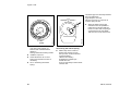
Adjusting the Throttle Cable
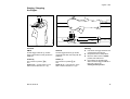
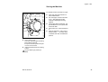
Mounting the Loop Handle
Control Handle1) with Slide*
P
STO
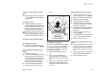
:
On the control handle, check that
the slide (arrow) in the slot below
the throttle trigger interlock is at the
bottom of the slot.
1
:
249BA017 KN
002BA162 KN
2
2
Press down the trigger interlock (1)
and squeeze the throttle trigger (2)
(full throttle) – this sets the throttle
cable correctly.
1
If the slide is not at the end of the slot:
:
1)
*
Use a screwdriver to push the slide
to the bottom of the slot (see
illustration).
002BA160 KN
002BA163 KN
002BA098 KN
1
Loop handle with barrier bar
:
:
Insert square nuts (1) in the
barrier bar (2).
Line up the holes.
This setting procedure causes the slide
to move away from the end of the slot.
On bike-handled versions only
see "Guide to Using this Manual"
KM 85, KM 85 R
13
english / USA
2
4
8
7
8
7
4
A
9
4
3
5
:
Place the clamp (3) in the loop
handle (4) and position them both
against the drive tube (5).
Fit the clamp (6) and place the
barrier bar (2) in position.
Note correct position.
:
Line up the holes.
:
:
1
1
002BA147 KN
002BA099 KN
7
6
002BA136 KN
5
6
:
10
3
Loop handle without barrier bar
Securing the loop handle
:
Place the clamp (3) in the loop
handle (4) and position them both
against the drive tube (5).
:
Secure the loop handle (4)
approx. 8”/20cm (A) forward of
the control handle (9).
:
Fit the clamp (6) and line up the
holes.
:
Line up the loop handle.
:
Tighten down the screws firmly lock the nuts if necessary.
Fit washers (7) on screws (8).
Insert screws (7) in holes and screw
them into the barrier bar as far as
stop.
:
:
Insert screws (8) in holes and screw
on the square nuts (1) as far as
stop.
Go to “Securing the loop handle”.
:
Go to “Securing the loop handle”.
10 Sleeve*
*
14
see “Guide to Using this Manual”
KM 85, KM 85 R
english / USA
Fuel
This engine is certified to operate on
unleaded gasoline and with the mix
ratio 50:1.
Your two-stroke engine requires a
mixture of brand-name gasoline and
quality two-stroke engine oil with the
classification TC.
Use regular branded unleaded gasoline
with a minimum octane rating of 89
RON. If the octane rating of the regular
grade gasoline in your area is lower use
premium unleaded fuel.
Note: Units with a catalytic converter
require unleaded gasoline. The
efficiency of the catalytic converter can
drop more than 50 % if several tankfuls
of leaded gasoline are used.
Fuel with a lower octane rating may
result in preignition (causing "pinging")
which is accompanied by an increase in
engine temperature. This, in turn,
increases the risk of the piston seizure
and damage to the engine.
The chemical composition of the fuel is
also important. Some fuel additives not
only detrimentally affect elastomers
(carburetor diaphragms, oil seals, fuel
lines etc.), but magnesium castings as
well. This could cause running problems
or even damage the engine. For this
reason it is essential that you use only
name branded fuels!
KM 85, KM 85 R
Use only STIHL two-stroke engine oil or
equivalent branded two-stroke aircooled engine oils with the classification
TC for mixing.
We recommend STIHL 50:1 two-stroke
engine oil since it is specially formulated
for use in STlHL engines.
Do not use BIA or TCW (two-stroke
water cooled) mix oils.
Use only STIHL 50:1 heavy-duty
engine oil or equivalent quality two
stroke engine oils for the fuel mix in
models with a catalytic converter.
Gasoline
Oil (STIHL 50:1 or
equivalent branded TC oils)
US gal.
1
2 1/2
5
US fl.oz
2.6
6.4
12.8
Dispose empty mixing-oil canisters only
at authorized disposal locations.
Take care when handling gasoline.
Avoid direct contact with the skin and
avoid inhaling fuel vapour.
The canister should be kept tightly
closed in order to avoid any moisture
getting into the mixture.
The fuel tank and the canister in which
fuel mix is stored should be cleaned
from time to time.
Fuel mix ages
Only mix sufficient fuel for a few days
work, not to exceed 3 months of storage.
Store in approved safety fuel-canisters
only. When mixing, pour oil into the
canister first, and then add gasoline.
15
english / USA
389BA031 KN
389BA032 KN
Fueling
Before fueling, clean the filler cap and
the area around it to ensure that no dirt
falls into the tank.
Always thoroughly shake the mixture in
the canister before fueling your
machine.
Change the fuel pick up body every
year.
Before storing your machine for a long
period, drain and clean the fuel tank and
run engine until carburetor is dry.
In order to reduce the risk of burns
or other personal injury from
escaping gas vapor and fumes,
remove the fuel filler cap carefully
so as to allow any pressure build-up
in the tank to release slowly.
After fueling, tighten fuel cap as
securely as possible by hand.
16
KM 85, KM 85 R
english / USA
Starting / Stopping
the Engine
3
65 4
P
STO
7
1
3
2
65 4
7
002BA167 KN
1
STOP
3
Controls
002BA168 KN
2
Starting
KM 85
KM 85 R
:
Throttle trigger interlock (1), throttle
trigger (2) and slide control (3) with the
positions:
Throttle trigger interlock (1), throttle
trigger (2) and slide control (3) with the
positions:
Hold down the trigger interlock and
squeeze the throttle trigger.
:
Keep both levers in that position.
:
START (4)
START (4)
Move the slide control to START
position and hold it there.
The normal run position # (5)
and
STOP–O (6) – to stop engine, move
slide control in direction of c(7).
The normal run position # (5)
and
STOP–O (6) – to stop engine, move
slide control in direction of c(7).
:
Now release the throttle trigger,
slide control and trigger interlock in
that order. This is the
starting-throttle position.
KM 85, KM 85 R
17
english / USA
:
Set the choke lever (8):
For cold start to g
For warm start to e
even if engine has been running but
is still cold
:
Press the fuel pump bulb (9) at least
five times, even if the bulb is still
filled with fuel.
357BA033 KN
002BA038 KN
002BA040 KN
9
393BA018 KN
8
393BA017 KN
8
:
Place the unit on the ground:
It must rest securely on the engine
support. Check that the tool is not
touching the ground or any other
obstacles – see also chapter
"Starting/Stopping the Engine" in
the CombiTool’s instruction manual.
:
Make sure you have a firm footing.
:
Press the unit firmly against the
ground with your left hand on the fan
housing. Your thumb should be
under the fan housing.
:
Pull the starter grip slowly with your
right hand until you feel it engage –
and then give it a brisk strong pull.
Do not pull out starter rope to full
length – it might break.
:
Do not let the starter grip snap back
– guide it slowly into the housing so
that the starter rope can rewind
properly.
:
Crank the engine until it runs.
Do not stand or kneel on the drive
tube!
18
KM 85, KM 85 R
english / USA
When engine begins to fire
If the engine still does not start
:
:
Move the slide control in direction of
arrow (c) to STOP-O.
Set the choke lever to e and
continue cranking.
10
Remove the spark plug boot (10).
:
Unscrew and dry off the spark plug.
:
Blip the throttle trigger so that the
slide control moves to the normal
run position # and the engine settles
down to idle speed.
:
Open the throttle wide.
:
Crank the engine several times with
the starter to clear the combustion
chamber.
Make sure the carburetor is
correctly adjusted – the tool must
not move when the engine is idling.
:
Refit the spark plug. Connect the
spark plug boot (press it down
firmly).
:
Move slide control to START.
:
Set the choke lever to e, even if the
engine is cold.
:
Now start the engine.
393BA019 KN
:
As soon as engine runs
Your machine is now ready for
operation.
To shut down the engine:
If the engine does not start
:
If you did not turn the choke knob to e
quickly enough after the engine began to
fire, the combustion chamber has
flooded.
Move the slide control in direction of
arrow (c) to STOP-O.
At very low outside temperatures
:
As soon as engine runs:
Blip the throttle trigger to disengage
the starting throttle position. The
slide control moves to the normal
run position # and the engine settles
down to idle speed.
:
Open the throttle slightly.
:
Warm up engine for brief period.
KM 85, KM 85 R
:
Turn choke knob to e
:
Set slide control, interlock lever and
throttle trigger to starting throttle
position.
:
Start the engine by pulling the
starter rope firmly. 10 to 20 pulls
may be necessary.
Fuel tank run until dry
:
After refueling, press the fuel pump
bulb at least five times – even if bulb
is filled with fuel.
:
Set the choke lever according to
engine temperature.
:
Now start the engine.
19
english / USA
Operating Instructions
Cleaning the Air Filter
2
As all moving parts have to bed in during
the break-in period, the frictional
resistances in the engine are greater
during this period. The engine develops
its maximum power after about 5 to 15
tank fillings.
3
During operation
After finishing work
Wait for engine to cool down. Drain the
fuel tank. Store the machine in a dry
place. Check tightness of nuts and
screws (not adjusting screws) at regular
intervals and retighten as necessary.
20
4
2
1
5
355BA014 KN
After a long period of full-throttle
operation, allow engine to run for a while
at idle speed so that the heat in the
engine can be dissipated by flow of
cooling air. This protects enginemounted components (ignition,
carburetor) from thermal overload.
Dirty air filters reduce engine power
increase fuel consumption and make
starting more difficult.
If there is a noticeable loss of engine
power
355BA032 KN
A factory new machine should not be run
at high revs (full throttle off load) for the
first three tank fillings. This avoids
unnecessary high loads during the
break-in period.
355BA031 KN
During break-in period
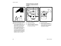
:
Wash the foam element in a clean,
non-flammable cleaning solution
(e.g. warm soapy water) and then
dry.
:
Fit new felt element.
As a temporary measure you can
knock it out on the palm of your
hand or blow it out with compressed
air. Do not wash.
:
Move choke lever to g.
:
Press in the tab (1).
:
Ease the filter cover (2) over the tab
and take it away.
:
Clean away loose dirt from around
the filter.
:
Install the foam element (3) in the
filter cover (2).
:
Remove the foam and felt filter
elements.
:
Place felt element (4) (lettering
facing inward) in filter housing (5).
:
Fit filter cover so that it snaps into
position.
Replace damaged parts!
KM 85, KM 85 R
english / USA
Spark Arresting Screen* in
Muffler
Motor Management
Exhaust emissions are controlled by the
design of the fundamental engine
parameters and components (e.g.
carburation, ignition, timing and valve or
port timing) without the addition of any
major hardware.
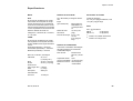
Adjusting the Carburetor
H
3/4
L
1
265BA024 KN
392BA035 KN
LA
If the engine is low on power, check the
spark arresting screen in the muffler.
The carburetor comes from the factory
with a standard setting.
:
Lift spark arresting screen and pull it
out sideways.
:
Clean spark arresting screen if
necessary.
This setting provides an optimum fuel-air
mixture under most operating
conditions.
:
If screen is damaged or coked up, fit
a new one.
:
Refit the spark arresting screen.
*
see “Guide to Using this Manual”
KM 85, KM 85 R
With this carburetor it is only possible to
adjust the high speed screw within fine
limits.
21
english / USA
Standard Setting
:
Shut off the engine.
:
Mount the CombiTool.
:
Check the air filter and clean or
replace as necessary.
:
Check the spark arresting screen
and clean or replace as necessary.
:
Turn high speed screw (H)
counterclockwise (max. 3/4 turn) as
far as stop.
At high altitude
:
Carefully screw the low speed
screw (L) down onto its seat. Then
open it one full turn counterclockwise.
:
Start and warm up the engine.
:
Adjust idle speed with the idle speed
screw (LA) so that the tool does
move.
Fine Tuning for Operation at High
Altitude or at Sea Level
A slight correction of the setting of the
high speed screw (H) may be necessary
if engine power is not satisfactory when
operating at high altitude, at sea level or
after changing the cutting tool.
22
:
Rule of thumb
1
Warm up the engine for about 3
minutes.
Turn high speed screw (H) about /4
turn for every 1000 m (3300 ft)
change in altitude.
Engine stops while idling
:
Carry out standard setting.
:
:
Warm up engine for about 3
minutes.
:
Turn high speed screw (H) clockwise (leaner) no further than stop.
CombiTool moves when engine is
idling
:
At sea level
:
Turn high speed screw (H) counterclockwise (richer) no further than
stop.
Maximum engine speed is normally
reached with the standard setting in
each case.
Adjusting Idle Speed
Turn idle speed screw (LA) slowly
clockwise until the engine runs
smoothly – the tool must not move.
Turn idle speed screw (LA) counterclockwise until the tool stops moving
and then turn the screw about
another 1/2 to 1 turn in the same
direction.
Erratic idling behavior, engine stops
even though setting of LA screw is
correct, poor acceleration
:
Idle setting too lean:
Turn low speed screw (L)
counterclockwise (about 1/4 turn)
until the engine runs and
accelerates smoothly.
It is usually necessary to change the
setting of the idle speed screw (LA)
after every correction to the low speed
screw (L).
KM 85, KM 85 R
english / USA
Checking the Spark Plug
Erratic idling behavior
:
If engine is down on power, difficult to
start or runs poorly at idling speed, first
check the spark plug.
Idle setting too rich:
Turn low speed screw (L) clockwise
(about 1/4 turn) until the engine runs
and accelerates smoothly.
:
Remove spark plug - see “Starting /
Stopping the Engine“.
:
Clean dirty spark plug.
:
Check electrode gap (A) and
readjust if necessary – see
"Specifications".
:
Use only resistor type spark plugs
of the approved range.
000BA002 KN
Rectify problems which have caused
fouling of spark plug:
Wrong fuel mix (too much engine oil in
the gasoline), a dirty air filter and
unfavorable running conditions (mostly
at part throttle etc.) affect the condition of
the spark plug. These factors cause
deposits to form on the insulator nose
which may result in trouble in operation.
KM 85, KM 85 R
:
Too much oil in fuel mix.
:
Dirty air filter.
:
Unfavorable running conditions,
e.g. operating at part load.
Fit a new spark plug after approx. 100
operating hours
or earlier if the electrodes are badly
eroded.
23
english / USA
Replacing the Starter Rope
and Rewind Spring
1
4
5
2
To reduce the risk of fire and burn
injury, use only spark plugs
authorized by STIHL. Always press
spark plug boot (2) snugly onto
terminal (1) of the proper size.
(Note: If boot has detachable SAE
adapter nut, it must be attached.)
A loose connection between spark
plug boot and ignition wire
connector in the boot may create
arcing that could ignite combustible
fumes and cause a fire.
24
1
3
392BA014 KN
000BA036 TR
1
386BA004 KN
1
:
Take out the screws (1).
:
Take out the screw (5).
:
Remove the cable lug (if fitted).
:
:
Lift the starter cover (2) away from
the tank (3) and pull it out from
under the shroud (4).
Remove the rope rotor very
carefully – the rewind spring is
seated in the rope rotor and may
pop out and uncoil if care is not
taken.
KM 85, KM 85 R
english / USA
Replacing a broken rewind spring
392BA024 KN
6
7
:
Lubricate the new spring with a few
drops of non-resinous oil – see
“Special Accessories“–, do not open
the wire retainer
:
Remove the rope rotor.
:
Remove parts of old spring.
:
Fit the new spring –
position outer spring loop in the
recess – the wire retainer slips off in
this process.
:
Use a screwdriver to ease the cap
(6) out of the starter grip.
:
Remove remaining rope from the
rotor and grip, making sure the
ElastoStart sleeve is not pushed out
of the grip.
:
Tie a simple overhand knot in the
end of the new starter rope – see
"Specifications" – and then thread
the rope through the top of the grip
and the rope bush (7).
:
Refit the cap in the grip.
KM 85, KM 85 R
392BA025 KN
392BA015 KN
8
:
Pull the rope through the rotor and
secure it with a simple overhand
knot.
:
Coat rope rotor bearing bore with
non-resinous oil – see “Special
Accessories“.
:
Slide rotor onto starter post –
turn it back and forth until the rewind
spring anchor loop (8) engages.
:
Insert screw and tighten down
securely.
Go to "Tensioning the rewind
spring".
:
25
english / USA
The starter grip must be firmly seated in
the rope guide bush.
If grip droops to one side:
Add one more turn on rope rotor to
increase spring tension.
If the spring has popped out:
Refit it in the counterclockwise
direction –
starting outside and working inward.
:
Install the rope rotor.
:
Check dimension "a" on inner
spring loop and bend it to size if
necessary.
:
Go to "Tensioning the rewind
spring".
26
When the starter rope is fully
extended it must be possible to
rotate the rotor another half turn.
If this is not the case, the spring is
overtensioned and could break.
Take one turn of rope off the rotor.
355BA021 KN
a = 2mm
(0.08in)
355BA022 KN
:
Tensioning the rewind spring
:
Make a loop in the unwound
starter rope and use it to turn
the rope rotor six full revolutions
counterclockwise.
Hold the rotor steady –
straighten the twisted rope –
release the rotor –
let go of rope slowly so that it winds
onto the rotor.
KM 85, KM 85 R
english / USA
Storing the Machine
386BA005 KN
For periods of about 3 months or longer:
:
Fit the starter cover.
To do this, push the upper mounting
boss under the shroud –
line up the tank and push lower part
of cover onto the tank.
:
Insert and tighten down the housing
screws.
:
Drain and clean the fuel tank in a
well ventilated area.
:
Run the engine until the carburetor
is dry – this helps prevent the
carburetor diaphragms sticking
together.
:
Thoroughly clean the machine - pay
special attention to the cylinder fins
and the air filter.
:
Remove the tool – clean and inspect
it.
:
Store the machine in a dry, high or
locked location – out of the reach
of children and other unauthorized
persons.
Secure cable lug in position (if
fitted).
KM 85, KM 85 R
27
english / USA
Complete machine
Visual inspection (condition,
leaks)
X
Air filter
Filter in fuel tank
Check operation
X
X
X
Clean
X
X
Replace
X
Check
X
Replace
X
X
Fuel tank
Clean
Carburetor
Check idle adjustment – working
tool must not move
Spark plug
Readjust electrode gap
X
Spark arresting screen* in muffler
Accessible screws and nuts
(not adjusting screws)
Antivibration elements
Inspect
X
X
X
X
X
Clean
Inspect
X
X
X
Retighten
replaced1)
X
X
Replace
Have
X
X
Readjust idle
Cooling inlets
as required
if damaged
if problem
every 12
months
monthly
weekly
after each
refueling stop
X
X
Clean
Control handle
after finishing
work or daily
Please note that the following maintenance intervals apply for normal operating
conditions. If your daily working time is longer than normal or working conditions
are difficult (very dusty work area, etc.), shorten the specified intervals accordingly.
before
starting work
Maintenance Chart
X
1)
By STIHL dealer
* See “Guide to Using this Manual”
28
KM 85, KM 85 R
english / USA
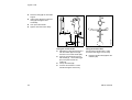
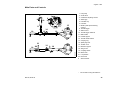
Main Parts and Controls
1 Fuel pump
9
8
2 Choke lever
1
10
2
3
3 Carburetor adjusting screws
4
6
7 Muffler (with spark arresting
screen*)
15
11
13
5 Fuel filler cap
6 Fuel tank
5
19
4 Starter grip
7
8 Throttle trigger
14
13
#
9 Slide control
16
10 Throttle trigger interlock
11 Bike handle
22 12
18
12 Handle support
13 Throttle cable retainer
17
14 Carrying ring
15 Spark plug boot
21
22
18
17 Machine support
18 Wing screw
19 Coupling sleeve
8
462BA000 KN
19 20
16 Air filter cover
14 9
10
20 Barrier bar*
21 Loop handle
22 Drive tube
#
*
KM 85, KM 85 R
Serial number
see "Guide to Using this Manual"
29
english / USA
Definitions
1.
Fuel Pump
Provides additional fuel feed for a
cold start.
10. Throttle Trigger Interlock
Must be depressed before the
throttle trigger can be activated.
19. Coupling Sleeve
Connects the drive tube to the lower
part of the drive tube (stub shaft).
2.
Choke Lever
Eases engine starting by enriching
mixture.
11. Bike Handle
For easy control of the machine with
both hands.
3.
Carburetor Adjusting Screws
For tuning the carburetor
12. Handle Support
Connects the drive tube and bike
handle.
20. Barrier Bar
Helps maintain clearance between
working tool and feet and legs of
operator.
4.
Starter Grip
The grip of the pull starter, which is
the device to start the engine.
5.
Fuel Filler Cap
For closing the fuel tank.
6.
Fuel Tank
For fuel mixture consisting of
gasoline and oil.
7.
Muffler
(with spark arresting screen)
Reduces exhaust noises and
diverts exhaust gases away from
operator.
8.
Throttle Trigger
Controls the speed of the engine.
9.
Slide Control
For starting throttle, run and stop.
Keeps the throttle partially open
during starting, switches the
engine’s ignition off to stop the
engine.
30
13. Throttle Cable Retainer
Secures the throttle cable to the
drive tube.
14. Carrying Ring
Connects the machine to the
harness.
21. Loop Handle
For easy control of the machine.
22. Drive Tube
Encloses and protects the drive
shaft between the engine and
gearhead.
15. Spark Plug Boot
Connects the spark plug to the
ignition lead.
16. Air Filter Cover
Encloses and protects the air filter.
17. Machine Support
For resting machine on the ground.
18. Wing Screw
Secures the lower part of the drive
tube (stub shaft).
KM 85, KM 85 R
english / USA
Specifications
Engine
Ignition System
Rewind Starter
EPA:
Type: Electronic magneto ignition
Spark plug
(resistor type):
Bosch WSR 6 F,
NGK BPMR 7 A
or Champion
RCJ 6Y
Electrode gap:
0.02 in (0.5 mm)
Spark plug thread: M 14 x 1.25;
0.37 in (9.5 mm)
long
Starter rope:
0.12 in (3.0 mm) diameter,
33.5 in (850 mm) long
The Emission Compliance Period
referred to on the Emissions
Compliance Label indicates the number
of operating hours for which the engine
has been shown to meet Federal
emission requirements.
Category A = 300 hours, B = 125 hours,
C = 50 hours
CARB:
The Emission Compliance Period used
on the CARB Air Index Label indicates
the terms:
Extended = 300 hours
Intermediate = 125 hours
Moderate = 50 hours
Single cylinder two-stroke engine
Displacement:
1.55 cu.in
(25.4cm3)
Bore:
1.34 in (34 mm)
Stroke:
1.10 in (28 mm)
Engine power to
ISO 8893:
1.3 bhp
(0.95 kW)
Idle speed:
2,800 rpm
Max. engine
speed:
10,500 rpm
KM 85, KM 85 R
Weight
dry, without CombiTool
9.3 lbs (4.2 kg)
KM 85 1)
2)
KM 85 R
8.8 lbs (4.0 kg)
1)
Version with bike handle
2)
Version with loop handle
Fuel System
Carburetor: All position diaphragm
carburetor with integral fuel pump
Air filter:
Foam and felt
elements
Fuel tank capacity: 0.93 US.pt
(0.44 L)
Fuel mix:
See chapter
"Fuel"
31
english / USA
Special Accessories
Maintenance and Repairs
Safety glasses
The user of this unit should carry out
only the maintenance operations
described in this manual. Other repair
work may be performed only by an
authorized STIHL dealer.
Shoulder strap
Full harness
Combination wrench
Carburetor screwdriver
STIHL ElastoStart (starter rope with grip)
Special resin-free lubricating oil
Contact your STIHL dealer for the latest
information on these and other special
accessories.
See also the information on special
accessories in your CombiTool
instruction manual.
32
Warranty claims following repairs can be
accepted only if the repair has been
performed by an authorized STIHL
dealer using original STIHL replacement
parts.
Original STlHL parts can be identified by
the STIHL part number, the STIHl
logo and the STlHL parts symbol (.
The symbol may appear alone on small
parts.
KM 85, KM 85 R
english / USA
STIHL Incorporated Federal and California
Emission Control Warranty Statement
Your Warranty Rights
and Obligations
The U.S. Environmental Protection
Agency (EPA), the California Air
Resources Board (CARB) and STIHL
Incorporated are pleased to explain the
Emission Control System Warranty on
your model year 2000 and later
equipment type engine. In California,
new small off-road engines must be
designed, built and equipped to meet the
State's stringent anti-smog standards. In
other states, new 1997 and later model
year small off-road equipment engines
must be designed, built and equipped, at
the time of sale, to meet the U.S. EPA
regulations for small non road engines.
The equipment engine must be free from
defects in materials and workmanship
which cause it to fail to conform with
U.S. EPA standards for the first two
years of engine use from the date of sale
to the ultimate purchaser.
STIHL Incorporated must warrant the
emission control system on your small
off-road engine for the period of time
listed below provided there has been no
abuse, neglect or improper maintenance
of your small off-road equipment engine.
Your emission control system includes
parts such as the carburetor and the
ignition system. Also included may be
hoses, and connectors and other
emission related assemblies.
KM 85, KM 85 R
Where a warrantable condition exists,
STIHL Incorporated will repair your
small off-road equipment engine at no
cost to you, including diagnosis (if the
diagnostic work is performed at an
authorized dealer), parts, and labor.
Manufacturer's Warranty
Coverage:
The small off-road equipment engines
are warranted for two years in California.
In other states, 1997 and later model
year small off-road equipment engines
are also warranted for two years. If any
emission-related part on your engine is
defective, the part will be repaired or
replaced by STIHL Incorporated free of
charge.
Owner's Warranty
Responsibilities:
As the small off-road equipment engine
owner, you are responsible for the performance of the required maintenance
listed in your owner's manual. STIHL
Incorporated recommends that you
retain all receipts covering maintenance
on your small off-road equipment
engine, but STIHL Incorporated cannot
deny warranty solely for the lack of
receipts or for your failure to ensure the
performance of all scheduled
maintenance.
Any replacement part or service that is
equivalent in performance and durability
may be used in non-warranty maintenance or repairs, and shall not reduce the
warranty obligations of the engine
manufacturer.
As the small off-road equipment engine
owner, you should be aware, however,
that STIHL Incorporated may deny you
warranty coverage if your small off-road
equipment engine or a part has failed
due to abuse, neglect, improper
maintenance or unapproved
modifications.
You are responsible for presenting your
small off-road equipment engine to a
STIHL service center as soon as a
problem exists. The warranty repairs will
be completed in a reasonable amount of
time, not to exceed 30 days.
If you have any questions regarding your
warranty rights and responsibilities,
please contact a STIHL customer
service representative at
1-800-467-8445 or you can write to
STIHL Inc., 536 Viking Drive,
P.O. Box 2015,
Virginia Beach, VA 23450-2015.
Coverage by STIHL Incorporated
STIHL Incorporated warrants to the
ultimate purchaser and each
subsequent purchaser that your small
off-road equipment engine will be
designed, built and equipped, at the time
of sale, to meet all applicable
regulations. STIHL Incorporated also
warrants to the initial purchaser and
each subsequent purchaser that your
engine is free from defects in materials
and workmanship which cause the
engine to fail to conform with applicable
regulations for a period of two years.
33
english / USA
Warranty Period
Warranty Work
Maintenance Requirements
The warranty periods will begin on the
date the utility equipment engine is
purchased by the initial purchaser and
you have signed and sent back the
warranty card to STIHL. If any emission
related part on your engine is defective,
the part will be replaced by STIHL
Incorporated at no cost to the owner.
Any warranted part which is not
scheduled for replacement as required
maintenance, or which is scheduled only
for regular inspection to the effect of
"repair or replace as necessary" will be
warranted for the warranty period.
Any warranted part which is scheduled
for replacement as required maintenance will be warranted for the period of
time up to the first scheduled replacement point for that part.
STIHL Incorporated shall remedy warranty defects at any authorized STIHL
servicing dealer or warranty station. Any
such work shall be free of charge to the
owner if it is determined that a warranted
part is defective. Any manufacturerapproved or equivalent replacement part
may be used for any warranty
maintenance or repairs on emissionrelated parts and must be provided
without charge to the owner. STIHL
Incorporated is liable for damages to
other engine components caused by the
failure of a warranted part still under
warranty.
The maintenance instructions in this
manual are based on the application of
the recommended 2-stroke fuel-oil
mixture (see also instruction "Fuel").
Deviations from this recommendation
regarding quality and mixing ratio of fuel
and oil may require shorter maintenance
intervals.
Diagnosis
You, as the owner, shall not be charged
for diagnostic labor which leads to the
determination that a warranted part is
defective. However, if you claim
warranty for a component and the
machine is tested as non-defective,
STIHL Incorporated will charge you for
the cost of the emission test.
Mechanical diagnostic work will be
performed at an authorized STIHL
servicing dealer. Emission test may be
performed either at STIHL Incorporated
or at any independent test laboratory.
34
The California Air Resources Board's
Emission Warranty Parts List specifically
defines the emission-related warranted
parts. These warranted parts are:
Carburetor
Choke (Cold start enrichment system)
Intake manifold
Air filter
Spark plug
Magneto or electronic ignition system
(ignition module)
Catalytic converter (if applicable)
Fasteners
Where to make a claim for
Warranty Service
Limitations
This Emission Control Systems Warranty shall not cover any of the following:
:
repair or replacement required
because of misuse, neglect or lack
of required maintenance,
:
repairs improperly performed or
replacements not conforming to
STIHL Incorporated specifications
that adversely affect performance
and/or durability, and alterations or
modifications not recommended or
approved in writing by STIHL
Incorporated,
and
:
replacement of parts and other
services and adjustments
necessary for required maintenance
at and after the first scheduled
replacement point.
Bring the product to any authorized
STIHL servicing dealer and present the
signed warranty card.
KM 85, KM 85 R
español / EE.UU
© 2002 Andreas Stihl AG & Co., Waiblingen
0458 462 8621. M3. K2. PM. Printed in USA
Impreso en papel sin cloro
Las tintas contienen aceites vegetales,
el papel es reciclable
Contenido
CombiSystem .................................
Guía para el uso
de este manual ...............................
Medidas de seguridad y
técnicas de manejo ........................
Herramientas CombiTool
aprobadas ......................................
Montaje del manillar .......................
Ajuste del cable del acelerador ......
Montaje del mango tórico ...............
Combustible ...................................
Llenado de combustible .................
Arranque / parada del motor ...........
Instrucciones de manejo ................
Limpieza del filtro de aire ...............
Chispero* en silenciador ................
Manejo del motor ............................
Ajuste del carburador .....................
Revisión de la bujía ........................
Sustitución de la cuerda
de arranque y resorte
de rebobinado ................................
Almacenamiento de la máquina .....
Tabla de mantenimiento .................
Controles y piezas
principales ......................................
Especificaciones .............................
Accesorios especiales ....................
Mantenimiento y reparación ...........
Declaración de garantía de
STIHL Incorporated sobre
sistemas de control de emisiones
según normas Federales y
del Estado de California .................
*
36
37
38
45
45
47
47
49
50
51
54
54
55
55
55
57
Permita que solamente las personas
que comprenden la materia tratada en
los manuales del motor CombiEngine y
de la herramienta CombiTool manejen
su herramienta motorizada.
Para obtener el rendimiento y satisfacción máximos de la herramienta motorizada STIHL, es importante leer y comprender las instrucciones de
mantenimiento y precauciones de seguridad, que empiezan en la página 4,
antes de usarlo.
Comuníquese con el concesionario o
distribuidor de STIHL si no se entiende
alguna de las instrucciones dadas en los
dos manuales.
58
61
62
63
65
66
66
67
vea "Guía para el uso de este
manual"
STIHl
KM 85, KM 85 R
35
español / EE.UU
CombiSystem
Hay manuales de instrucciones distintos
para el motor CombiEngine y la herramienta CombiTool.
!Advertencia
La filosofía de STIHL es mejorar continuamente todos su productos. Como
resultado de ello, periódicamente se
introducen cambios de diseño y mejoras. Por lo tanto, STIHL no puede responsabilizarse por los cambios, modificaciones o mejoramientos que no hayan
sido cubiertos en este manual. Si las
características de funcionamiento o la
apariencia de su herramienta motorizada difieren de las descritas en este
manual, comuníquese con el concesionario STIHL para obtener la información
y ayuda que requiera.
36
+
Siempre lea y asegúrese que comprenda bien ambos manuales de instrucciones antes de arrancar y usar la
máquina. Guarde los manuales en un
lugar seguro para referencia futura.
En las cortadoras de matorrales con
brazo dividido (modelos T), se
puede usar la herramienta CombiTool en vez de cualquier accesorio
para herramienta motorizada.
..
..
+
002BA159 KN
Dado que la herramienta es una herramienta motorizada de gran velocidad, es
necesario tomar medidas especiales de
seguridad para reducir el riesgo de
lesiones. El uso descuidado o inadecuado puede causar lesiones graves e
incluso mortales.
El sistema CombiSystem™ de STIHL
consta de varias combinaciones de
motores CombiEngine y herramientas
CombiTool. En este manual de instrucciones la unidad formada por el motor
CombiEngine™ y la herramienta CombiTool™ se identifica como la herramienta motorizada.
KM 85, KM 85 R
español / EE.UU
Guía para el uso de este
manual
Pictogramas
Todos los pictogramas que se encuentran en la máquina se muestran y explican en este manual.
Las instrucciones de uso y manipulación
vienen acompañadas de ilustraciones.
Símbolos en el texto
Los pasos individuales o procedimientos
descritos en el manual pueden estar
señalados en diferentes maneras:
:
Paso o procedimiento sin referencia
directa a una ilustración.
Descripción del paso o procedimiento
que se refiere directamente a la ilustración y contiene los números de referencia que aparecen en la ilustración.
Ejemplo:
Suelte el tornillo (1)
Palanca (2) ...
Además de las instrucciones de uso,
en este manual pueden encontrarse
párrafos a los que usted debe prestar
atención especial. Tales párrafos están
marcados con los símbolos que se
describen a continuación:
Advertencia donde existe el
riesgo de un accidente o lesiones
personales o daños graves a la
propiedad.
Advertencia donde existe el
riesgo de dañar la máquina o
los componentes individuales.
Nota o sugerencia que no es
esencial para el uso de la máquina,
pero puede ayudar al operador a
comprender mejor la situación y
mejorar su manera de manejar la
máquina.
Nota o sugerencia sobre el p
rocedimiento correcto con el fin
de evitar dañar el medio ambiente.
Equipo y características
Este manual de instrucciones
abarca varios modelos con diferentes características. Los componentes que no se encuentran instalados
en todos los modelos y las aplicaciones correspondientes están marcados con un *. Esos componentes
son ofrecidos como accesorios
especiales por el concesionario
STIHL.
Mejoramientos técnicos
La filosofía de STIHL es mejorar continuamente todos su productos. Como
resultado de ello, periódicamente se
introducen cambios de diseño y mejoras. Si las características de funcionamiento o la apariencia de su máquina
difieren de las descritas en este manual,
comuníquese con el concesionario
STIHL para obtener la ayuda que
requiera.
Por lo tanto, no podemos responsabilizarnos por los cambios, modificaciones
o mejoramientos que no hayan sido
cubiertos en este manual.
KM 85, KM 85 R
37
español / EE.UU
Medidas de seguridad y técnicas de manejo
Advertencia
Dado que este CombiEngine es el motor para una
herramienta motorizada
que funciona a gran velocidad, es necesario tomar
medidas especiales de
seguridad para reducir el riesgo de
lesiones personales.
Es importante que usted
lea, comprenda bien y
respete las siguientes
advertencias y medidas
de seguridad. Lea el
manual del usuario y las
instrucciones de seguridad del motor
CombiEngine y de la herramienta CombiTool periódicamente. El uso descuidado o inadecuado de cualquier herramienta motorizada puede causar
lesiones graves e incluso mortales.
Pida a su concesionario STIHL que le
enseñe el manejo de la herramienta
motorizada. Respete todas las disposiciones, reglamentos y normas de seguridad locales del caso.
!Advertencia
No preste ni alquile nunca su herramienta motorizada sin entregar el
manual del usuario. Asegúrese que
todas las personas que utilicen la herramienta motorizada lean y comprendan
la información contenida en este
manual.
38
!Advertencia
EL OPERADOR
Nunca se debe permitir a los niños que
usen una herramienta motorizada. No
se debe permitir la proximidad de otros,
especialmente niños y animales, donde
se esté utilizando la herramienta motorizada.
Condición física
Nunca deje la herramienta motorizada
funcionando sin vigilancia.
Usted debe estar en buenas condiciones físicas y psíquicas y no encontrarse
bajo la influencia de ninguna sustancia
(drogas, alcohol, etc.) que le pueda restar visibilidad, destreza o juicio. No
maneje una herramienta motorizada
cuando está fatigado.
Las medidas de seguridad y avisos contenidos en este manual se refieren al
uso de todas las herramientas motorizadas STIHL. Los distintos modelos pueden contar con piezas y controles diferentes. Vea la sección correspondiente
de su manual del usuario para tener una
descripción de los controles y la función
de cada componente de su herramienta
motorizada.
Esté alerta. Si se cansa durante el
manejo de la herramienta motorizada,
tómese un descanso. El cansancio
puede provocar una pérdida del control.
El uso de cualquier herramienta motorizada es fatigoso. Si usted padece de
alguna dolencia que pueda ser agravada por la fatiga, consulte a su médico
antes de utilizar la herramienta motorizada.
El uso seguro de una herramienta motorizada atañe a
!Advertencia
1.
el operador
2.
la herramienta motorizada
3.
el uso de la herramienta motorizada.
El sistema de encendido de la máquina
STIHL produce un campo electromagnético de intensidad muy baja. El mismo
puede interferir con algunos tipos de
marcapasos. Para reducir el riesgo de
lesiones graves o mortales, las personas portadoras de marcapasos deben
consultar a sus médicos y al fabricante
del marcapasos antes de usar esta
máquina.
KM 85, KM 85 R
español / EE.UU
Vestimenta adecuada
LA HERRAMIENTA MOTORIZADA
!Advertencia
Para las ilustraciones y definiciones de
los componentes de la herramienta
motorizada, vea el capítulo "Piezas y
controles".
Para reducir el riesgo de lesiones el
operador debe usar el equipo protector
adecuado.
!Advertencia
Para reducir el riesgo de
lesionarse los ojos, nunca
maneje la herramienta
motorizada si no tiene
puestas gafas o anteojos
de seguridad bien ajustados con una protección adecuada en las
partes superior y laterales que satisfagan la norma ANSI Z 87.1 (o la norma
nacional correspondiente).
!Advertencia
Nunca modifique, de ninguna manera,
una herramienta motorizada. Utilice únicamente las herramientas CombiTools
suministradas por STIHL o expresamente autorizados por STIHL para
usarse con los motores Combiengine
específicos de STIHL. Si bien es posible
conectar al motor CombiEngine de
STIHL ciertos accesorios no autorizados, su uso puede ser, en la práctica,
extremadamente peligroso.
!Advertencia
El ruido del motor CombiEngine puede dañar sus
oídos. Siempre use amortiguadores del ruido
(tapones u orejeras) para
protegerse los oídos. Los
usuarios constantes y regulares deben
someterse con frecuencia a un examen
o control auditivo.
Para instrucciones adicionales acerca
de la ropa adecuada, vea las "Instrucciones de seguridad" en el manual del propietario de la CombiTool.
KM 85, KM 85 R
Preparación para el uso de la herramienta motorizada
Siempre revise la condición y funcionamiento de su herramienta motorizada
antes de ponerla en marcha, especialmente el gatillo de aceleración, el bloqueo del gatillo de aceleración (si lo
tiene), el interruptor de parada, la herramienta motorizada, el deflector y el
arnés.
El gatillo de aceleración debe moverse
libremente y siempre debe retornar a la
posición de ralentí por la acción de
resorte. La herramienta motorizada
debe estar correctamente apretada y en
buenas condiciones de trabajo. Busque
piezas sueltas (tuercas, tornillos, etc.) y
herramientas motorizadas agrietadas,
dobladas, deformadas o dañadas.
USO DE LA HERRAMIENTA
MOTORIZADA
Transporte de la herramienta motorizada
!Advertencia
Antes de apoyar la herramienta motorizada en el suelo, apague el motor y asegúrese de que el accesorio ha dejado de
girar. Cuando transporte la herramienta
motorizada en un vehículo, sujétela firmemente para impedir su vuelco, el
derrame de combustible y el daño a la
herramienta motorizada.
39
español / EE.UU
Llenado de combustible
La herramienta motorizada STIHL utiliza
una mezcla de aceite-gasolina como
combustible (vea el capítulo "Combustible" en el manual del usuario).
!Advertencia
La gasolina es un combustible muy inflamable.
Si se derrama y arde a
causa de una chispa u
otra fuente de ignición,
puede provocar un incendio y quemaduras graves o daños a la
propiedad. Tenga sumo cuidado cuando
manipule gasolina o la mezcla de combustible.
No fume cerca del combustible o la
herramienta motorizada, ni acerque ningún fuego o llama a ellos.
Instrucciones para el llenado de combustible
!Advertencia
Cargue de combustible su herramienta
motorizada en lugares al aire libre bien
ventilados. Siempre apague el motor y
deje que se enfríe antes de llenar de
combustible. Dependiendo del combustible utilizado, de las condiciones climáticas y del sistema de ventilación del
tanque, es posible que se forme vapor
de gasolina a presión dentro del tanque
de combustible.
Para reducir el riesgo de quemaduras,
así como otras lesiones corporales ocasionadas por los escapes de vapor de
gasolina y otras emanaciones, quite la
tapa de llenado de combustible de la
herramienta motorizada cuidadosamente de modo que la presión que se
pueda haber acumulado en el tanque se
disipe lentamente. Nunca quite la tapa
de llenado de combustible mientras el
motor está funcionando.
!Advertencia
Para reducir el riesgo de incendio o
lesiones por quemadura, deje que la
máquina se enfríe antes de reabastecer
de combustible la herramienta motorizada después de haberla usado.
Elija una superficie despejada para llenar el tanque y aléjese 3 m (10 pies) por
lo menos del lugar en que lo haya llenado antes de arrancar el motor. Limpie
los derrames de combustible antes de
arrancar la herramienta motorizada y
compruebe que no existen fugas.
!Advertencia
Compruebe que no existen fugas de
combustible mientras llena el tanque y
durante el funcionamiento de la
máquina. Si detecta alguna fuga de
combustible o aceite, no arranque el
motor ni lo haga funcionar sin antes
reparar la fuga y limpiar el combustible
derramado. Tenga cuidado de no mancharse la ropa con combustible. En tal
caso, cámbiese la ropa inmediatamente.
Tapa con empuñadura
!Advertencia
Para reducir el riesgo de derramar combustible y provocar un incendio debido a
una tapa de combustible mal apretada,
coloque la tapa en la posición correcta y
apriétela en la boca de llenado del tanque.
Para hacer esto con esta
tapa STIHL, levante la
empuñadura en la parte
superior de la tapa hasta
dejarla vertical a un
ángulo de 90°. Inserte la
tapa en la boca de llenado del tanque,
alineando las marcas triangulares en la
empuñadura de la tapa y en la boca del
tanque. Utilizando la empuñadura, gire
la tapa firmemente en sentido horario
hasta donde tope (aprox. un cuarto de
vuelta).
Doble la empuñadura
dejándola a ras con la
parte superior de la tapa.
Si no queda totalmente a
ras y el tope en la empuñadura no encaja en el
hueco correspondiente en el cuello de
llenado, la tapa está mal asentada y
apretada, se deberán repetir los pasos
anteriores.
El tipo de tapa de llenado difiere con los
distintos modelos.
40
KM 85, KM 85 R
español / EE.UU
Tapa roscada
!Advertencia
Las vibraciones de la
máquina pueden aflojar
una tapa de combustible
que ha quedado mal
apretada, o simplemente
soltarla y derramar combustible. Para reducir el riesgo de derrames e incendio, apriete la tapa de llenado de combustible a mano con la
mayor fuerza posible.
Instrucciones de manejo
! Advertencia
El uso indebido de cualquier herramienta motorizada puede causar lesiones graves o mortales. Para reducir el
riesgo de lesiones del operador causadas por el funcionamiento de la herramienta motorizada, siempre respete las
instrucciones de seguridad para el uso
de la herramienta motorizada indicadas
en los manuales de propietario del
motor CombiEngine y la herramienta
CombiTool.
Arranque
!Advertencia
Su herramienta motorizada es una
máquina que debe ser manejada por
solamente una persona. Para reducir el
riesgo de lesiones, mantenga a los
espectadores fuera de la zona de trabajo (vea los manuales CombiTool para
las distancias específicas).
KM 85, KM 85 R
Apague el motor y la herramienta de
corte inmediatamente si se le aproxima
alguna persona. Ponga en marcha y
maneje su herramienta motorizada sin
ayuda de nadie. Para las instrucciones
específicas de arranque, vea la sección
correspondiente de los manuales. Coloque la herramienta motorizada sobre
suelo firme u otra superficie sólida en un
lugar abierto. Mantenga buen equilibrio
con los pies bien apoyados.
Silenciador
!Advertencia
!Advertencia
Para reducir el riesgo de lesiones
debido a la pérdida de control, esté
absolutamente seguro que la herramienta motorizada se encuentra lejos de
su cuerpo y de todas las obstrucciones
y objetos, incluido el suelo, porque al
arrancar el motor acelerado, su velocidad será lo suficientemente rápida para
que el embrague se engrane y haga funcionar la herramienta motorizada.
El silenciador y otros componentes del
motor (por ej., aletas del cilindro, bujía)
se calientan durante el funcionamiento y
permanecen calientes por un buen rato
después de apagar el motor. Para reducir el riesgo de quemaduras, no toque el
silenciador y otros componentes mientras están calientes.
!Advertencia
Cuando tire del mango de arranque, no
enrolle la cuerda de arranque alrededor
de la mano. No deje que el mango retroceda bruscamente, sino guíe la cuerda
de arranque para que se enrolle debidamente. Si no ejecuta este procedimiento
puede lastimarse la mano o los dedos y
también dañar el mecanismo de arranque.
!Advertencia
Nunca maneje su herramienta motorizada si el silenciador está dañado, se ha
perdido o si fue modificado. El silenciador podría causar el aumento de la
radiación de calor o chispas, aumentando así el riesgo de incendio o lesiones por quemadura. Además, se podría
dañar permanentemente el motor.
!Advertencia
Para reducir el riesgo de incendio o
lesiones por quemadura, mantenga limpia la zona alrededor del silenciador.
Cuando el motor está apagado y frío,
quite toda la basura tal como las agujas
de pinos, ramas u hojas.
Vea también las "Instrucciones de seguridad" en el manual del propietario de la
CombiTool.
41
español / EE.UU
Convertidor catalítico
!Advertencia
Algunos modelos de
herramientas motorizadas STIHL están equipados con un convertidor
catalítico, el que está
diseñado para reducir las
emisiones de escape del motor
mediante un proceso químico en el
silenciador. Debido a este proceso, el
silenciador no se enfría tan rápidamente
como los del tipo convencional cuando
el motor regresa a ralentí o es apagado.
Para reducir el riesgo de incendio y de
lesiones por quemadura, es necesario
respetar las siguientes medidas de
seguridad específicas.
!Advertencia
Como un silenciador con convertidor
catalítico se enfría más lentamente que
los silenciadores convencionales, no
apoye nunca su herramienta motorizada
sobre o cerca de material seco como por
ejemplo matorrales, pasto o virutas de
madera, o sobre otros materiales combustibles mientras todavía está caliente.
Deje que el motor se enfríe apoyado
sobre una superficie de hormigón,
metal, suelo raso o madera maciza,
lejos de cualquier sustancia combustible.
42
!Advertencia
!Advertencia
Una caja de cilindro dañada o mal instalada, o una envuelta del silenciador
dañada o deformada, puede perjudicar
el efecto de enfriamiento del convertidor
catalítico. Para reducir el riesgo de
incendio o lesiones por quemadura, no
continúe trabajando con una caja de
cilindro dañada o mal instalada, o una
envuelta del silenciador dañada o deformada. El convertidor catalítico está
dotado de rejillas diseñadas para reducir
el riesgo de incendio debido a la emisión
de partículas calientes. Debido al calor
de la reacción catalítica, estas rejillas
normalmente permanecen limpias y no
necesitan servicio o mantenimiento. Si
el rendimiento de su máquina comienza
a disminuir y sospecha que las rejillas
están obstruidas, haga reparar el silenciador por un concesionario de servicio
STIHL.
Su herramienta motorizada emite gases de
escape tóxicos apenas el
motor empieza a funcionar. Estos gases (por ej.,
monóxido de carbono)
pueden ser incoloros e inodoros. Para
reducir el riesgo de sufrir lesiones graves o mortales por respirar gases tóxicos, nunca haga funcionar la herramienta motorizada puertas adentro o en
lugares mal ventilados.
Condiciones de trabajo
Maneje y arranque su herramienta
motorizada solamente al aire libre en un
lugar bien ventilado.
Maneje la herramienta motorizada solamente en condiciones de buena visibilidad y a la luz del día. Trabaje con mucho
cuidado.
!Advertencia
El uso de este producto puede generar
polvo y vapores que contienen productos químicos considerados como causantes de enfermedades respiratorias,
cáncer, defectos de nacimiento u otra
toxicidad reproductora. Si usted desconoce los riesgos asociados con el polvo
o vapor en cuestión, consulte con su
empleador, autoridades gubernamentales tales como OSHA y NIOSH y otras
fuentes de información sobre materiales
peligrosos. El Estado de California y
algunas otras autoridades han publicado varias listas de sustancias carcinógenas, de toxicidad reproductora, etc.
KM 85, KM 85 R
español / EE.UU
Siempre que sea posible, controle el
polvo y los vapores en su punto de origen. Al respecto, emplee buenas prácticas de trabajo y siga las recomendaciones de OSHA/NIOSH y asociaciones
laborales y comerciales. Cuando sea
imposible eliminar la inhalación del
polvo o vapores tóxicos, el operador y
las personas que se encuentren en la
cercanía siempre deberán usar un respirador aprobado por NIOSH/MSHA para
el tipo de polvo y/o vapores presentes
en el lugar.
MANTENIMIENTO, REPARACION
Y ALMACENAMIENTO
Ajustes importantes
Los trabajos de mantenimiento,
reemplazo o reparación de los dispositivos y sistemas de control de emisiones de escape pueden ser realizados por cualquier taller o técnico de
motores no diseñados para vehículos. Sin embargo, si usted está reclamando cobertura de garantía para
algún componente que no ha sido
reparado o mantenido debidamente,
o cuando se utilizan repuestos no
autorizados, STIHL puede denegar la
garantía.
!Advertencia
!Advertencia
Para reducir el riesgo de lesiones personales debido a la pérdida de control o al
contacto con la herramienta motorizada
en movimiento, no use una herramienta
cuyo ralentí está mal regulado. Cuando
el ralentí está correctamente regulado,
la herramienta motorizada no debe girar.
Para instrucciones de ajuste del ralentí,
vea la sección correspondiente en el
manual del usuario. Si no puede regular
correctamente el ralentí, pida a su concesionario STIHL que revise la herramienta motorizada y haga los ajustes o
reparaciones correspondientes.
KM 85, KM 85 R
Utilice solamente piezas de repuesto de
STIHL para el mantenimiento y reparación. El uso de piezas no fabricadas por
STIHL puede aumentar el riesgo de
lesiones graves o mortales.
Siga las instrucciones de mantenimiento
y reparación dadas en la sección correspondiente del manual del usuario. Consulte la tabla de mantenimiento en las
últimas páginas de este manual.
!Advertencia
Siempre apague el motor y asegúrese
que la herramienta de corte está detenida antes de hacer cualquier trabajo de
mantenimiento, reparación o limpieza
de la herramienta motorizada. No
intente hacer ningún trabajo de mantenimiento o reparación que no esté descrito en su manual del usuario. Este tipo
de trabajo debe realizarse únicamente
en el taller de servicio de STIHL.
Use guantes para manipular o reparar la
cuchilla.
!Advertencia
Nunca repare los accesorios de corte
dañados aplicándoles soldadura, enderezándolos o modificándoles su forma.
Esto puede causar el desprendimiento
de alguna pieza de la herramienta de
corte y producir lesiones graves o mortales.
43
español / EE.UU
!Advertencia
!Advertencia
Para reducir el riesgo de incendio y de
quemaduras, revise si hay fugas en la
tapa de llenado de combustible en intervalos regulares. Use la bujía especificada y asegúrese de que ella y el cable
de encendido están limpios y en buen
estado. Siempre inserte el casquillo de
la bujía bien apretado en el borne de la
bujía del tamaño adecuado. (Nota: Si el
casquillo tiene una tuerca adaptadora
SAE desmontable, tiene que ser instalada.) Una conexión suelta entre el casquillo de la bujía y el conector del cable
de encendido en el casquillo puede
crear un arco voltaico y encender los
vapores del combustible, provocando
un incendio.
Un silenciador dañado o mal cuidado
aumenta el riesgo de incendio y puede
causar pérdida del oído. No toque nunca
un silenciador caliente, puede quemarse. Si el silenciador está equipado
con un chispero para reducir el riesgo de
incendio (por ejemplo, en EE.UU.,
Canadá y Australia), no haga funcionar
el motor CombiEngine si le falta el chispero o si el mismo está dañado. No desarme, modifique ni retire ninguna pieza
del silenciador o chispero. Recuerde
que el riesgo de incendios forestales es
mayor durante las estaciones calurosas
y secas. Haga reparar el silenciador únicamente por el concesionario de servicio STIHL.
!Advertencia
Mantenga afilado el accesorio de corte.
Apriete todas las tuercas, pernos y tornillos, excepto los tornillos de ajuste del
carburador, después de cada uso.
No pruebe nunca el sistema de encendido con el casquillo del cable de encendido desconectado de la bujía, o sin
tener instalada la bujía, ya que las chispas al descubierto pueden causar un
incendio.
44
Además, es imprescindible seguir el
programa de mantenimiento diario indicado en el manual del usuario de la
herramienta motorizada STIHL.
Para todo trabajo de mantenimiento, sírvase consultar la tabla de mantenimiento y la declaración de garantía
que se encuentra al final de este
manual.
Guarde la herramienta motorizada en un
lugar seco, elevado o con llave lejos del
alcance de los niños.
Antes de guardar la máquina durante un
período de más de algunos días, siempre vacíe el tanque de combustible.
Consulte el capítulo "Almacenamiento
de la máquina".
KM 85, KM 85 R
español / EE.UU
Herramientas CombiTool
aprobadas
Las siguientes herramientas CombiTool
de STIHL pueden instalarse en el motor
CombiEngine:
FS
CombiTool
FS 1)
HL-0/90°
FS 1) 2)
HL-0°
FH 2) 3)
HL - 0° 3)
HL - 0/90° 2) 3)
HT 3)
BC 2) 3)
FCB, FCS 3)
KW 3)
FH
HT
BC
1)
KW
KM 85, KM 85 R
Siempre respete las indicaciones del
capítulo "Combinaciones aprobadas
de herramienta de corte, deflector,
mango y arnés" en el manual de instrucciones FS CombiTool.
2)
La barra de defensa debe instalarse en el mango tórico
3)
No es adecuada ni aprobada para
los motores CombiEngine con manillar de bicicleta
5
1
4
3
A
2
:
Instale el manillar (1) en el tubo de
mando (2) a aproximadamente
16 pulg (40 cm) (A) delante del
motor.
:
Coloque la abrazadera (3) y el
soporte del manillar (4) en el tubo
de mando.
:
Ponga el manillar (1) en su soporte
- la empuñadura de caucho debe
quedar a la izquierda (vista desde el
motor)
932BA001 KN
FCS
FCB
Propósito
Cortadora de matorrales con cabeza
segadora
Cortadora de matorrales con cuchilla
para recortar pasto
Motoguadaña
Cortasetos
Cortasetos
Podador de varilla
Cultivadora
Orilladora
Barredora PowerSweep
6
6
002BA128 KN
FS
Montaje del manillar
45
español / EE.UU
:
Coloque la abrazadera (5) en el
soporte del manillar.
:
Inserte los tornillos (6) en los agujeros.
:
Coloque las tuercas (7) en los tornillos y apriételas hasta que topen.
:
Alinee el manillar.
:
Apriete los tornillos firmemente.
13
11
10
9
7
14
12
14
8
13
14
46
002BA129 KN
12
393BA005 KN
1
Instalación del mango de control
Instalación del cable del acelerador
:
Afloje el tornillo (7) y retírelo con la
arandela (8). La tuerca (9) permanece en el mango de control (10).
No tuerza el cable del acelerador - asegúrese de que el gatillo se mueva libremente.
:
Empuje el mango de control en el
manillar (1) - el gatillo de aceleración (11) debe apuntar hacia el
mecanismo.
:
:
Alinee los agujeros (12).
:
Coloque el tornillo y la arandela en
el mango de control y apriételos firmemente.
Inserte el cable del acelerador (13)
en los retenedores (14).
KM 85, KM 85 R
español / EE.UU
Ajuste del cable del acelerador
Montaje del mango tórico
Manija de control1)
con pieza deslizante*
P
STO
En la manija de control, verifique
que la pieza deslizante (flecha) esté
en el extremo de la ranura que está
debajo del bloqueo del gatillo de
aceleración.
:
2
Oprima el bloqueo (1) y oprima el
gatillo de aceleración (2) (aceleración máxima) – esto ajusta el cable
del acelerador correctamente.
1
1
Si la pieza deslizante no está en el
extremo de la ranura:
:
1)
*
002BA160 KN
002BA163 KN
002BA098 KN
:
1
249BA017 KN
002BA162 KN
2
Este procedimiento de ajuste desplaza
la pieza deslizante fuera del extremo de
la ranura.
Mango tórico con barra de
defensa
:
Inserte las tuercas cuadradas (1) en
la barra de defensa (2).
:
Alinee los agujeros.
Utilice un destornillador para empujar la pieza deslizante hasta la parte
inferior de la ranura (vea la ilustración).
Versión con manillar de bicicleta
solamente
vea “Guía para el uso de este
manual”
KM 85, KM 85 R
47
español / EE.UU
2
4
8
7
8
7
4
A
9
4
3
5
:
Coloque la abrazadera (3) en el
mango tórico (4) y ponga los dos en
posición contra el tubo de mando
(5).
Instale la abrazadera (6) y coloque
la barra de defensa (2) en posición.
Observe la posición correcta.
:
Alinee los agujeros.
:
Inserte los tornillos (7) en los agujeros y atorníllelos en la barra de
defensa hasta donde topen.
:
Prosiga a "Fijación del mango
tórico".
1
1
Mango tórico sin barra de
defensa
:
Coloque la abrazadera (3) en el
mango tórico (4) y ponga los dos en
posición contra el tubo de mando
(5).
:
Coloque las arandelas (7) en los
tornillos (8).
:
Inserte los tornillos (8) en los
agujeros y atorníllelos en las
tuercas cuadradas (1) hasta donde
topen.
:
Prosiga a "Fijación del mango
tórico".
002BA147 KN
002BA099 KN
7
6
002BA136 KN
5
6
:
10
3
Fijación del mango tórico
:
Fije el mango tórico (4) aprox. a
8 pulg (20 cm) (A) delante del
mango de control (9).
:
Alinee el mango tórico.
:
Apriete los tornillos firmemente y, si
es necesario, trabe las tuercas.
10 Manguito*
*
48
vea “Guía para el uso de este
manual”
KM 85, KM 85 R
español / EE.UU
Combustible
Este motor está homologado para funcionar con gasolina sin plomo y una proporción de mezcla de 50:1.
El motor de dos tiempos necesita una
mezcla de gasolina de buena marca y
aceite para motor de dos tiempos de
buena calidad clasificado TC.
Use gasolina regular sin plomo con un
octanaje mínimo de 89 RON. Si el octanaje de la gasolina regular en su zona
es más bajo, use gasolina superior sin
plomo ("premium").
Nota: Las máquinas con convertidor
catalítico requieren gasolina sin
plomo. La eficiencia del convertidor
catalítico puede reducirse por más del
50% si se llena el tanque de combustible
varias veces con gasolina con plomo.
El combustible de octanaje menor
puede producir preencendido (causando detonación) acompañado de un
aumento de la temperatura del motor.
Esto, a su vez, aumenta el riesgo de
agarrotamiento del pistón y daño al
motor.
La composición química del combustible también es importante. Algunos aditivos de combustible no solamente son
perjudiciales para los elastómeros (diafragmas del carburador, sellos de aceite,
mangueras de combustible, etc.), sino
también para las piezas fundidas de
magnesio. Esto podría causar problemas de funcionamiento o incluso dañar
el motor. Por este motivo es esencial
usar únicamente combustibles de
buena marca comercial.
KM 85, KM 85 R
En la mezcla, use únicamente aceite de
STIHL para motor de dos tiempos o
aceites para motor de dos tiempos
enfriado por aire con la clasificación TC.
Nosotros recomendamos el aceite 50:1
de STIHL para motor de dos tiempos
porque está especialmente formulado
para usarse en motores de STIHL.
No use aceites para mezcla BIA o TCW
(dos tiempos enfriado por agua).
En los modelos con convertidor
catalítico mezcle exclusivamente con la
gasolina el aceite de motor STIHL 50:1
para servicio severo o un aceite de
calidad equivalente para motores de dos
tiempos.
Sea precavido cuando trabaje con gasolina. Evite el contacto directo con la piel
y evite inhalar el vapor de combustible.
Mantenga el recipiente herméticamente
cerrado para evitar la entrada de humedad a la mezcla.
Limpie periódicamente el tanque de
combustible y el recipiente en que
guarda la mezcla de combustible.
Envejecimiento de la mezcla
de combustible
Mezcle únicamente el combustible
suficiente para unos pocos días de
trabajo, no lo guarde por más de 3
meses. Guárdelo solamente en recipientes especialmente aprobados para
combustible. Cuando prepare la mezcla,
primero vierta el aceite en el recipiente y
después incorpore la gasolina.
Gasolina
Aceite (STIHL 50:1 ó
aceites TC de marca
comercial equivalentes)
litros
ml
(gal. EE.UU.) (oz. fl. EE.UU.)
3,8
(1)
6,9
(2,6)
9,5 (2,5)
189,3
(6,4)
18,9
(5)
378,5 (12,8)
Deseche los recipientes vacíos de
aceite únicamente en vertederos
autorizados.
49
español / EE.UU
389BA031 KN
389BA032 KN
Llenado de combustible
Antes de llenar la máquina con combustible, limpie a fondo la tapa de llenado y
la zona alrededor del mismo para evitar
la entrada de tierra al tanque.
Cambie el recogedor de combustible una vez al año.
Siempre agite la mezcla vigorosamente
en el recipiente antes de llenar la
máquina con combustible.
Antes de almacenar la máquina por un
período prolongado, vacíe y limpie el
tanque de combustible y ponga el motor
en marcha hasta que se seque el combustible del carburador.
Para reducir el riesgo de quemaduras,
así como otras lesiones corporales
ocasionadas por los escapes de vapor
de gasolina y otras emanaciones,
quite la tapa de llenado de combustible
cuidadosamente de modo que la presión que se pueda haber acumulado
en el tanque se disipe lentamente.
Después de haber llenado la
máquina con combustible, apriete la
tapa del tanque tan firmemente
como sea posible con la mano.
50
KM 85, KM 85 R
español / EE.UU
Arranque / parada del motor
3
65 4
P
STO
7
1
3
2
65 4
7
002BA167 KN
1
STOP
3
Controles
002BA168 KN
2
Arranque
KM 85
KM 85 R
:
Bloqueo del gatillo de aceleración (1),
gatillo de aceleración (2) y control deslizante (3) con las posiciones:
Bloqueo del gatillo de aceleración (1),
gatillo de aceleración (2) y control deslizante (3) con las posiciones:
Mantenga oprimido el bloqueo del
gatillo y oprima el gatillo de aceleración.
:
ARRANQUE (4)
ARRANQUE (4)
Mantenga las dos palancas en esa
posición.
La posición normal de marcha # (5) ,
ralentí y STOP–O (6) – para apagar el
motor, mueva el control deslizante hacia
c(7).
La posición normal de marcha # (5) ,
ralentí y STOP-O (6) – para apagar el
motor, mueva el control deslizante hacia
c(7).
:
Mueva el control deslizante hacia la
posición de ARRANQUE (START)
y manténgalo en esa posición.
:
Ahora suelte el gatillo de aceleración, el control deslizante y el bloqueo del gatillo, en el orden indicado. Esta es la posición de
arranque del acelerador.
KM 85, KM 85 R
51
español / EE.UU
:
Coloque la palanca del estrangulador (8):
Para arranque en frío en g
Para arranque caliente en e aunque el motor haya funcionado pero
todavía está frío
:
Oprima el bulbo (9) de la bomba de
combustible por lo menos cinco
veces, aunque el bulbo esté lleno
de combustible.
357BA033 KN
002BA038 KN
002BA040 KN
9
393BA018 KN
8
393BA017 KN
8
:
Coloque la máquina sobre el suelo.
Debe quedar firmemente apoyada
en el soporte del motor. Asegúrese
que la herramienta no está tocando
el suelo ni otros obstáculos. Vea
también el capítulo "Arranque/
Parada del Motor" en el manual de
instrucciones de la CombiTool.
:
Asegúrese de tener los pies bien
apoyados.
:
Empuje la máquina firmemente
contra el suelo colocando la mano
izquierda sobre la caja del ventilador. Coloque el dedo pulgar debajo
de la caja del ventilador.
:
Con la mano derecha tire lentamente del mango de arranque hasta
que sienta una resistencia definitiva
y en seguida dele un tirón fuerte y
rápido. No tire de la cuerda de
arranque totalmente hasta afuera,
se podría cortar.
:
No deje que el mango de arranque
retroceda bruscamente; guíelo lentamente hacia el interior de la caja
de modo que la cuerda se enrolle
debidamente.
:
Continúe haciendo girar el motor
hasta que arranque.
No se pare ni se arrodille sobre el
tubo de mando.
52
KM 85, KM 85 R
español / EE.UU
breve.
Cuando el motor empieza a encenderse
:
:
Mueva la palanca del estrangulador
a e y continúe intentando el arranque del motor.
10
Tan pronto arranca
:
Si el motor todavía no arranca
Oprima el gatillo de aceleración
momentáneamente de modo que el
control deslizante se desplace a la
posición de marcha #, y el motor
retorne a aceleración de ralentí.
393BA019 KN
Asegúrese que el carburador esté
correctamente ajustado; la herramienta no debe moverse cuando el
motor está funcionando a ralentí.
Su máquina está lista para trabajar.
Para apagar el motor:
:
Mueva el control deslizante en el
sentido indicado por c a STOP-O.
A temperaturas ambiente muy
bajas
:
Tan pronto arranque:
Accione momentáneamente el gatillo de aceleración para desconectarlo de la posición de arranque. El
control deslizante se desplaza a la
posición de marcha # y el motor
retorna a aceleración de ralentí.
:
Abra el acelerador ligeramente.
:
Caliente el motor por un tiempo
KM 85, KM 85 R
Si el motor no arranca
Mueva el control deslizante en el
sentido indicado por c a STOP-O.
:
Quite el casquillo de la bujía (10).
:
Destornille y seque la bujía.
:
Abra el acelerador al máximo.
:
Haga girar el motor varias veces
con el arrancador para despejar la
cámara de combustión.
:
Vuelva a instalar la bujía. Conecte el
casquillo de la bujía (empújelo firmemente).
:
Mueva el control deslizante a la
posición START.
:
Ponga la palanca del estrangulador
en e – aun si el motor está frío.
:
Ahora arranque el motor.
Se agotó el combustible en el tanque
Si no se movió la perilla del estrangulador a e en un tiempo suficientemente
corto después que el motor empezó a
encenderse, la cámara de combustión
se encuentra "ahogada".
:
Después de llenar el tanque, oprima
el bulbo de la bomba de combustible por lo menos cinco veces, aunque el bulbo esté lleno de combustible.
:
Gire la perilla del estrangulador a
e
:
Ajuste la palanca del estrangulador
según la temperatura del motor.
:
Ponga el control deslizante, la
palanca de bloqueo y el gatillo de
aceleración en la posición de arranque.
:
Ahora arranque el motor.
:
Arranque el motor tirando enérgicamente de la cuerda de arranque.
Puede ser necesario hacer 10 a 20
intentos.
53
español / EE.UU
Instrucciones de manejo
Limpieza del filtro de aire
2
3
Después de terminar el trabajo
Espere que el motor se enfríe. Vacíe el
tanque de combustible. Almacene la
máquina en un lugar seco. Revise el
apriete de las tuercas y tornillos (no los
tornillos de ajuste) periódicamente y
vuelva a apretar según sea necesario.
54
1
5
355BA014 KN
Después de un período largo de funcionamiento con el acelerador a fondo,
deje funcionar el motor por un rato en
ralentí de modo que el calor en el motor
sea disipado por la corriente de aire de
enfriamiento. Esto ayuda a evitar que
los componentes montados en el motor
(encendido, carburador) sufran sobrecargas térmicas.
4
2
Durante el funcionamiento
355BA032 KN
Una máquina nueva no debe hacerse
funcionar a velocidad alta (aceleración
máxima sin carga) por el lapso que tome
llenar el tanque tres veces. Esto evita la
imposición de cargas innecesariamente
altas durante el período de rodaje.
Puesto que todas las piezas móviles
necesitan un período de rodaje, las
resistencias causadas por la fricción en
el motor son mayores durante este
período. El motor desarrolla su potencia
máxima después de haber llenado el
tanque de 5 a 15 veces.
355BA031 KN
Durante el período de rodaje
La suciedad en el filtro de aire reduce la
potencia del motor, aumenta el consumo
de combustible y dificulta el arranque
del motor.
:
Lave el elemento de espuma en una
solución limpiadora limpia y no inflamable (por ejemplo, agua jabonosa
tibia) y séquelo.
Si se nota una pérdida considerable
de la potencia del motor
:
Coloque un elemento de fieltro
nuevo. Como una medida provisoria, es posible limpiarlo golpeándolo
en la palma de la mano o soplándolo con aire comprimido. No lo
lave.
:
Ponga la palanca del estrangulador
en g
:
Oprima la lengüeta (1).
:
Levante cuidadosamente la
cubierta (2) del filtro encima de la
lengüeta y quítela.
:
Limpie toda la suciedad de alrededor del filtro.
:
Retire los elementos de espuma y
de fieltro del filtro.
Siempre sustituya las piezas dañadas.
:
Coloque el elemento de espuma (3)
en la cubierta (2) del filtro.
:
Coloque el elemento de fieltro (4)
(las marcas orientadas hacia adentro) en la caja del filtro (5).
:
Coloque la tapa del filtro de modo
que se trabe en su lugar.
KM 85, KM 85 R
español / EE.UU
Chispero* en silenciador
Manejo del motor
Las emisiones de gases de escape son
controladas por el diseño de parámetros
y componentes fundamentales del
motor (por ej. carburación, encendido,
regulación y regulación de la válvula o
lumbrera) sin la adición de ningún
equipo importante.
Ajuste del carburador
H
3/4
L
1
Si el motor pierde potencia, revise el
chispero del silenciador.
:
Levante el chispero y sáquelo de
lado.
:
Limpie el chispero, de ser necesario.
:
Si el chispero está dañado u obstruido, instale uno nuevo.
:
Vuelva a instalar el chispero.
*
vea "Guía para el uso de este
manual"
KM 85, KM 85 R
265BA024 KN
392BA035 KN
LA
El carburador se ajusta en la fábrica.
Este ajuste provee una mezcla óptima
de combustible y aire bajo la mayoría de
las condiciones de funcionamiento.
Con este carburador es posible ajustar
el tornillo de velocidad rápida dentro de
una gama pequeña.
55
español / EE.UU
Ajuste normal
:
Apague el motor.
:
Instale la CombiTool.
:
Revise el filtro de aire y límpielo o
sustitúyalo de ser necesario.
:
Revise el chispero y límpielo o instale uno nuevo de ser necesario.
:
Gire el tornillo de ajuste de velocidad alta (H) en sentido contrahorario hasta su tope (no más de 3/4 de
vuelta).
:
Atornille el tornillo de velocidad baja
(L) hasta que tope en su asiento.
Después ábralo una vuelta en sentido contrahorario.
:
Arranque el motor y caliéntelo.
:
Ajuste la velocidad de ralentí con el
tornillo (LA) hasta que la cuchilla
deje de girar.
Ajuste fino para trabajo a alturas
grandes o a nivel del mar
Puede ser necesario efectuar un ajuste
ligero del tornillo de velocidad alta (H) si
la potencia del motor no es adecuada
para trabajar en grandes altitudes o al
nivel del mar o después de cambiar la
herramienta de corte.
Regla general
Caliente el motor por aproximadamente 3 minutos.
Gire el tornillo de ajuste de velocidad alta (H) aproximadamente 1/4
de vuelta por cada 1000 metros
(3300 pies) de cambio de altura.
El motor se para durante el funcionamiento a ralentí
:
Lleve a cabo el ajuste normal.
:
:
Caliente el motor por aproximadamente 3 minutos.
Gire lentamente el tornillo de ajuste
de ralentí (LA) en sentido horario
hasta que el motor funcione de
modo suave - la herramienta segadora no debe girar.
En alturas grandes
:
Gire el tornillo de ajuste de velocidad alta (H) en sentido horario
(mezcla más pobre), pero no más
allá del tope.
La CombiTool funciona mientras el
motor está a ralentí
:
Al nivel del mar
:
Gire el tornillo de ajuste de velocidad alta (H) en sentido contrahorario (mezcla más rica), pero no más
allá del tope.
Normalmente se alcanza la velocidad máxima del motor con el ajuste
normal en cada caso.
Ajuste de ralentí
Gire el tornillo de ralentí (LA) lentamente en sentido contrahorario
hasta que la herramienta de corte
se detenga y luego gire el tornillo
otra media vuelta a vuelta completa
en el mismo sentido.
Funcionamiento irregular a ralentí, el
motor se para aunque se ha corregido el ajuste del tornillo LA, aceleración inadecuada
:
Generalmente es necesario cambiar el
ajuste del tornillo de ralentí (LA) después de cada corrección hecha al tornillo de velocidad baja (L).
56
:
Ajuste de ralentí con mezcla muy
pobre:
Gire el tornillo de velocidad baja (L)
en sentido contrahorario (aprox. 1/4
de vuelta) hasta que el motor funcione y se acelere de modo uniforme.
KM 85, KM 85 R
español / EE.UU
Revisión de la bujía
Funcionamiento irregular a ralentí
000BA002 KN
:
Si el motor tiene poca potencia, le
cuesta arrancar o funciona deficientemente a velocidad de ralentí, primero revise la bujía.
Ajuste de ralentí con mezcla muy
rica:
Gire el tornillo de velocidad baja (L)
en sentido horario (aprox. 1/4 de
vuelta) hasta que el motor funcione
y se acelere de modo uniforme.
La mezcla de combustible incorrecta
(demasiado aceite de motor en la gasolina), el filtro de aire sucio y condiciones
de funcionamiento desfavorables (generalmente a media aceleración, etc.)
afectan la condición de la bujía. Estos
factores causan la formación de depósitos en la punta del aislador lo que puede
dificultar el funcionamiento.
KM 85, KM 85 R
:
Saque la bujía - vea „Arranque /
parada del motor“.
:
Limpie la bujía sucia.
:
Mida la separación entre electrodos
de la bujía (A). Vuelva a ajustar si es
necesario. Vea “Especificaciones”.
:
Use únicamente bujías de tipo
resistencia de capacidad aprobada.
Corrija la causa de la suciedad de la
bujía:
:
Demasiado aceite en la mezcla de
combustible.
:
Filtro de aire sucio.
:
Condiciones de funcionamiento
desfavorables, por ej., funcionamiento a media aceleración.
Coloque una bujía nueva después de
100 horas de funcionamiento, aproximadamente, o más temprano si nota
que los electrodos están muy desgastados.
57
español / EE.UU
Sustitución de la cuerda de
arranque y resorte de rebobinado
1
4
5
2
Para reducir el riesgo de incendios y
lesiones por quemadura, use solamente bujías autorizadas por
STIHL. Siempre encaje un casquillo
(2) del tamaño correcto bien ajustado en el borne (1) de la bujía.
(Nota: Si el casquillo tiene una
tuerca adaptadora SAE desprendible, colóquela.) Una conexión
suelta entre el casquillo de la bujía y
el conector del alambre de encendido puede formar un arco eléctrico,
inflamar los vapores combustibles y
finalmente causar un incendio.
58
1
3
392BA014 KN
000BA036 TR
1
386BA004 KN
1
:
Saque los tornillos (1).
:
Saque el tornillo (5).
:
Quite el borne de cable.
:
:
Levante la tapa (2) de encima del
tanque (3) y extráigala de debajo de
la cubierta protectora (4).
Retire el rotor de la cuerda con
mucho cuidado. El resorte de rebobinado está alojado en el rotor y
puede saltar y desenrollarse si no
se procede con cuidado.
KM 85, KM 85 R
español / EE.UU
Sustitución de resorte de rebobinado roto
392BA024 KN
6
7
:
Lubrique el resorte nuevo con unas
pocas gotas de aceite sin resina**.
No abra el retenedor de alambre.
:
Quite el rotor de la cuerda.
:
Quite las piezas del resorte viejo.
:
Instale el resorte nuevo – coloque la
espiral exterior del resorte en la
hendidura – el alambre retenedor
se suelta durante este proceso.
:
Utilice un destornillador para quitar
la tapa (6) del mango de la cuerda
de arranque.
:
Retire la cuerda restante del rotor y
del mango, asegurándose de evitar
que el manguito ElastoStart se
salga del mango.
:
:
Haga un nudo de rizo sencillo en el
extremo de la cuerda de arranque
nueva y después pase la cuerda por
la parte superior del mango y por el
buje de la cuerda (7).
Vuelva a instalar la tapa en el
mango.
392BA025 KN
392BA015 KN
8
:
Tire de la cuerda a través del rotor y
fíjela con un nudo de rizo simple.
:
Cubra la cavidad del cojinete del
rotor de la cuerda con aceite sin
resina**.
:
Deslice el rotor en el poste del
arrancador. Gírelo hacia uno y otro
lado hasta que la espiral (8) del
resorte de rebobinado se enganche.
:
Inserte el tornillo y apriételo bien
firme. Pase a "Tensado del resorte
de rebobinado".
** vea "Accesorios especiales"
KM 85, KM 85 R
** vea "Accesorios especiales"
59
español / EE.UU
El mango de arranque debe quedar firmemente sentado en el buje guía de la
cuerda. Si el mango cae hacia un lado:
Dele una vuelta adicional al rotor de la
cuerda para aumentar la tensión del
resorte.
Si el resorte se sale: Colóquelo nuevamente en sentido contrahorario,
empezando desde el exterior y
avanzando hacia adentro.
:
Instale el rotor de la cuerda.
:
Compruebe la dimensión ”a” en la
espiral interior del resorte y dóblela
para ajustarla al tamaño correcto,
de ser necesario.
:
Pase a "Tensado del resorte de
rebobinado".
60
Cuando la cuerda de arranque se
extiende completamente, debe ser
posible girar el rotor media vuelta
adicional. En caso contrario, el
resorte está sobretensado y podría
romperse. Quítele una vuelta de la
cuerda al rotor.
355BA021 KN
a = 2mm
(0.08in)
355BA022 KN
:
Tensado del resorte de rebobinado
:
Forme un bucle con la cuerda de
arranque sin envolver y utilícelo
para girar el rotor seis revoluciones
completas en sentido contrahorario.
Sostenga el rotor inmóvil – enderece la cuerda – suelte el rotor –
suelte la cuerda lentamente de
modo que se enrolle en el rotor.
KM 85, KM 85 R
español / EE.UU
Almacenamiento de la
máquina
386BA005 KN
Para intervalos de 3 meses o más:
:
Instale la tapa del arrancador. Para
hacer esto, coloque el reborde de
montaje superior debajo de la
envuelta – alinee el tanque y
empuje la parte inferior de la tapa
sobre el tanque.
:
Inserte y apriete los tornillos de la
caja.
:
Vacíe y limpie el tanque de combustible en una zona bien ventilada.
:
Haga funcionar el motor hasta que
el carburador se seque. Esto ayuda
a evitar que los diafragmas del carburador se peguen.
:
Limpie la máquina a fondo - preste
atención especial a las aletas del
cilindro y al filtro de aire.
:
Retire, limpie e inspeccione la
herramienta.
:
Guarde la máquina en un lugar seco
y elevado, o bajo llave – fuera del
alcance de los niños y de otras personas no autorizadas.
Fije el borne del cable en posición.
KM 85, KM 85 R
61
español / EE.UU
Máquina completa
Inspección visual
(condición general, fugas)
X
Filtro de aire
Filtro en tanque de combustible
Comprobar funcionamiento
X
X
X
Revisar
X
Reemplazar
Carburador
Comprobar ajuste de ralentí - la
herramienta no debe moverse
X
X
Reemplazar
Limpiar
X
X
X
X
X
Entradas de enfriamiento
Chispero en silenciador*
X
Ajustar la distancia entre electrodos
Inspeccionar
X
X
Limpiar
Inspeccionar
X
Volver a apretar
Elementos antivibración
Cambiar1)
X
X
Reemplazar
Tornillos y tuercas accesibles
(no los tornillos de ajuste)
X
X
Ajustar el ralentí
Bujía
según se requiera
X
Limpiar
Tanque de combustible
si tiene daños
si hay problema
cada 12 meses
mensualmente
semanalmente
X
X
Limpiar
Mango de control
después de cada parada para cargar combustible
antes de comenzar el trabajo
Sírvase notar que los intervalos de mantenimiento siguientes son aplicables
en condiciones normales de funcionamiento. Si el tiempo de trabajo por jornada es más largo que lo normal, o si las condiciones son extremas (zonas
polvorientas, etc.), acorte los intervalos indicados de modo correspondiente.
después de terminar el trabajo o diariamente
Tabla de mantenimiento
X
X
X
1)
Concesionario STIHL
* Vea la “Guía para el uso de este manual”
62
KM 85, KM 85 R
español / EE.UU
Controles y piezas
principales
1 Bomba de combustible
9
8
2 Palanca del estrangulador
1
10
2
3
3 Tornillos de ajuste del carburador
4
5 Tapa de llenado de combustible
6 Tanque de combustible
5
6
7 Silenciador (con chispero*)
15
11
8 Gatillo de aceleración
13
19
4 Mango de arranque
7
14
13
#
9 Control deslizante
16
10 Bloqueo del gatillo de aceleración
11 Manillar de bicicleta
22 12
18
12 Soporte del manillar
13 Retenedor del cable del acelerador
14 Argolla de transporte
17
15 Casquillo de bujía
16 Cubierta del filtro de aire
21
22
18
18 Tornillo mariposa
19 Manguito de acoplamiento
8
20 Barra de defensa*
462BA000 KN
19 20
17 Apoyo de la máquina
14 9
10
21 Mango tórico
22 Tubo de mando
#
*
KM 85, KM 85 R
Número de serie
vea “Guía para el uso de este
manual”
63
español / EE.UU
Definiciones
1.
Bomba de combustible
Suministra alimentación adicional
de combustible para el arranque en
frío.
10. Bloqueo del gatillo de aceleración
Debe ser oprimido antes de poder
activar el gatillo de aceleración.
19. Manguito de acoplamiento
Conecta el tubo de mando a la parte
inferior del tubo de mando (eje
corto).
2.
Palanca del estrangulador
Facilita el arranque del motor al
enriquecer la mezcla.
11. Manillar tipo bicicleta
Para facilitar el control de la
máquina con ambas manos.
3.
Tornillos de ajuste del carburador
Para afinar el carburador
12. Soporte del manillar
Conecta el tubo de mando y el
manillar de bicicleta.
20. Barra de defensa
Ayuda a mantener el espacio libre
entre la herramienta CombiTool y
los pies y piernas del operador.
4.
Mango de arranque
El mango de la cuerda de arranque,
el cual es el dispositivo usado para
arrancar el motor.
13. Retenedor del cable del acelerador
Sujeta el cable del acelerador al
tubo de mando.
5.
Tapa de llenado de combustible
Para tapar el tanque de combustible.
14. Argolla de transporte
Conecta la máquina al arnés.
6.
Tanque de combustible
Contiene la mezcla de gasolina y
aceite.
7.
Silenciador
(con chispero)
Reduce los ruidos del tubo de
escape y desvía los gases de
escape lejos del operador.
8.
Gatillo de aceleración
Regula la velocidad del motor.
9.
Control deslizante
Para aceleración de arranque, marcha y parada. Mantiene el acelerador parcialmente abierto durante el
arranque, apaga el encendido del
motor y detiene su marcha.
64
21. Mango tórico
Para facilitar el control de la
máquina.
22. Tubo de mando
Encierra y protege el eje impulsor
entre el motor y el mecanismo.
15. Casquillo de bujía
Conecta la bujía al alambre de
encendido.
16. Cubierta del filtro de aire
Encierra y protege el filtro de aire.
17. Apoyo de la máquina
Para apoyar la máquina en el suelo.
18. Tornillo mariposa
Sujeta la parte inferior del tubo de
mando (eje corto).
KM 85, KM 85 R
español / EE.UU
Especificaciones
Motor
Sistema de encendido
Arrancador de cuerda
EPA:
Tipo: Encendido por magneto electrónico
Bujía
(tipo resistencia):
Bosch WSR 6 F,
NGK BPMR 7 A
o Champion RCJ
6Y
Distancia entre
0,5 mm (0,02
electrodos:
pulg)
Roscas de la bujía: M 14 x 1,25;
9,5 mm
(0,37 pulg) de
largo
Cuerda de arranque:
3,0 mm (0,12 pulg) de diámetro, 850
mm (33,5 pulg) de largo
El período de cumplimiento de emisiones indicado en la etiqueta de cumplimiento de emisiones es la cantidad de
horas de funcionamiento para la cual la
máquina ha demostrado la conformidad
con los requerimientos de emisiones del
Gobierno federal de los EE.UU.
Categoría A = 300 horas, B = 125 horas,
C = 50 horas
CARB:
El período de cumplimiento de emisiones empleado en la etiqueta del índice
de aire CARB tiene las siguientes definiciones:
Extended (extendido) = 300 horas
Intermediate (intermedio) = 125 horas
Moderate (moderado) = 50 horas
Motor de un cilindro, dos tiempos
Cilindrada:
25,4 cm3
(1,55 pulg cúb. )
Bore:
34 mm (1,34 pulg)
Stroke:
28 mm (1,10 pulg)
Potencia del
motor según ISO 0,95 kW
8893:
(1,3 bhp)
Idle speed:
2800 rpm
Velocidad máx.
del motor:
10.500 rpm
KM 85, KM 85 R
Peso
Seco, sin CombiTool
KM 85 1)
4,2 kg (9,3 lb)
2)
KM 85 R
4,0 kg (8,8 lb)
1)
Versión con manillar de bicicleta
2)
Versión con mango tórico
Sistema de combustible
Carburador: Carburador de diafragma
de todas posiciones con bomba de
combustible integral
Filtro de aire:
Elementos de
espuma y de fieltro
Capacidad del tan- 0,44 l
que de combustible: (0,93 pt EE.UU.)
Mezcla de combus- Vea el capítulo
tible:
"Combustible"
65
español / EE.UU
Accesorios especiales
Mantenimiento y reparación
Anteojos de seguridad
El usuario de esta máquina deberá realizar solamente los trabajos de mantenimiento descritos en este manual. Otros
trabajos de reparación debe hacerlos
solamente un técnico de servicio autorizado por STIHL.
Correa para hombro
Arnés completo
Llave combinada
Destornillador para el carburador
ElastoStart de STIHL (cuerda de arranque con mango)
Aceite lubricante especial libre de resina
Póngase en contacto con el concesionario STIHL para obtener la información
más reciente sobre éstos y otros accesorios especiales.
Vea también la información acerca de
accesorios especiales en el manual de
instrucciones de la CombiTool.
66
Los reclamos de garantía serán aceptados únicamente si la reparación fue
hecha por un concesionario de servicio
autorizado por STIHL usando repuestos
originales de STIHL.
Los repuestos originales de STIHL se
pueden identificar por el número de
pieza de STIHL, el logotipo STIHl
y el símbolo de piezas de STIHL(
(
En las piezas pequeñas, el símbolo
puede aparecer solo.
KM 85, KM 85 R
español / EE.UU
Declaración de garantía de STIHL Incorporated sobre sistemas de control de emisiones según normas Federales y del
Estado de California
Sus derechos y obligaciones de
garantía
La Agencia de Protección del Medio
Ambiente (EPA) de los EE.UU., el Consejo de Recursos del Aire del Estado de
California (CARB) y STIHL Incorporated
se complacen en explicarle la garantía
del sistema de control de emisiones instalado en el motor de su equipo de
modelos año 2000 y siguientes. En California, los nuevos motores pequeños
para uso fuera de carretera deben estar
diseñados, construidos y equipados de
conformidad con las rigurosas normas
de contaminación del aire del estado. En
otros estados, los modelos 1997 y posteriores de tales motores deben estar
diseñados, construidos y equipados, al
tiempo de la venta, de conformidad con
los reglamentos correspondientes de la
EPA. El motor debe carecer de defectos
en el material y la fabricación que puedan causar el incumplimiento de las normas de la EPA durante los primeros dos
años de uso del motor a partir de la
fecha de compra por el último comprador. STIHL Incorporated debe garantizar
el sistema de control de emisiones en el
motor pequeño para uso fuera de carretera por el intervalo mencionado más
arriba, siempre que dicho motor no haya
estado sujeto a maltrato, negligencia o
cuidado inapropiado.
El sistema de control de emisiones de
su máquina incluye piezas tales como el
carburador y el sistema de encendido.
Además puede incluir mangueras,
conectores y otros conjuntos relativos a
emisiones.
KM 85, KM 85 R
Si existe una condición amparada bajo
garantía, STIHL Incorporated reparará
el motor sin costo alguno, incluido el
diagnóstico (si el trabajo de diagnóstico
fue realizado por un concesionario autorizado), las piezas y la mano de obra.
Cobertura de garantía del fabricante:
Los motores pequeños para equipos de
uso fuera de carretera están garantizados por dos años en el Estado de California. En otros estados, los modeles de
1997 y posteriores de tales motores
también están garantizados por dos
años. En el caso de encontrarse defectos en cualquiera de las piezas del
motor relacionadas con el sistema de
control de emisiones, la pieza será reparada o sustituida por STIHL Incorporated sin costo alguno.
Responsabilidades del usuario
relativas a la garantía:
Como propietario de tal motor, usted
tiene la responsabilidad de realizar el
mantenimiento requerido descrito en su
manual del usuario. STIHL Incorporated
le recomienda guardar todos los recibos
comprobantes de los trabajos de mantenimiento hechos a su motor, pero STIHL
Incorporated no puede negar garantía
basado en el solo hecho de faltar los
recibos o del incumplimiento del propietario de realizar todos los trabajos de
mantenimiento programados.
El uso de cualquier pieza de repuesto o
servicio cuyo comportamiento y durabilidad sean equivalentes está permitido en
trabajos de mantenimiento o reparación
no contemplados en la garantía, y no
reducirá las obligaciones de la garantía
del fabricante del motor.
Sin embargo, como propietario del
motor pequeño para equipo de uso
fuera de carretera usted debe ser consciente de que STIHL Incorporated
puede negarle cobertura de garantía si
dicho motor o una pieza del mismo ha
fallado debido a maltrato, descuido,
mantenimiento inadecuado o modificaciones no autorizadas.
Usted es responsable de llevar el motor
a un centro de servicio STIHL tan pronto
surja el problema. Las reparaciones
bajo garantía serán realizadas en un
tiempo razonable, sin exceder de 30
días. Ante cualquier duda respecto a
sus derechos y responsabilidades
según lo estipulado en esta garantía,
comuníquese con el representante de
STIHL al 1-800-467-8445 ó escriba a
STIHL Inc., 536 Viking Drive, P.O. Box
2015, Virginia Beach, VA 23450-2015.
Cobertura por STIHL Incorporated
STIHL Incorporated garantiza al último
comprador y a cada comprador subsiguiente que el motor pequeño para
equipo de uso fuera de carretera está
diseñado, construido y equipado, al
tiempo de la venta, de conformidad con
todos los reglamentos aplicables. Además, STIHL Incorporated garantiza al
comprador inicial y a cada comprador
subsiguiente que el motor está libre de
defectos en el material y fabricación que
puedan causar el incumplimiento de los
reglamentos aplicables durante un
período de dos años.
67
español / EE.UU
Período de garantía
Trabajo bajo garantía
El período de garantía comienza en la
fecha en que el motor del equipo utilitario es entregado a usted y usted firma y
remite la tarjeta de garantía a STIHL.
Si cualquier pieza relacionada con el
sistema de control de emisiones está
defectuosa, la pieza será sustituida por
STIHL Incorporated sin costo alguno
para el propietario. Cualquier pieza
garantizada cuyo reemplazo no está
programado como mantenimiento
requerido, o que debe recibir únicamente inspección regular en el sentido
de "reparar o sustituir según sea necesario", estará garantizada por el período
de garantía. Cualquier pieza cuyo reemplazo está programado como mantenimiento requerido estará garantizada por
el intervalo hasta el primer punto de
reemplazo programado para esa pieza.
STIHL Incorporated reparará los defectos amparados por la garantía en cualquier estación de garantía o centro de
servicio autorizado por STIHL. Todo trabajo de este tipo se hará gratis para el
propietario siempre que se determine
que la pieza cubierta por la garantía está
defectuosa. Se puede usar cualquier
pieza de repuesto aprobada por el fabricante o equivalente en las piezas relacionadas con el sistema de control de
emisiones, y debe ser suministrada gratis al propietario. STIHL Incorporated es
responsable por daños a otros componentes del motor causados por la falla
de una pieza garantizada que todavía
está bajo garantía.
Diagnóstico
Como propietario, a usted no se le debe
cobrar la mano de obra por los diagnósticos que determinen que una pieza
garantizada está defectuosa. No obstante, si usted reclama garantía para un
componente y se comprueba que la
máquina no está defectuosa, STIHL
Incorporated le cobrará el costo de la
prueba del sistema de control de emisiones.
El trabajo de diagnóstico mecánico se
realiza en un centro de servicio autorizado por STIHL. La prueba del sistema
de control de emisiones se realiza ya
sea en la fábrica de STIHL Incorporated
o en un laboratorio de ensayos independiente.
68
La lista de piezas del sistema de control
de emisiones garantizadas del Consejo
de Recursos del Aire del Estado de California define específicamente las piezas
garantizadas que están relacionadas
con las emisiones. Estas piezas garantizadas son:
Carburador
Estrangulador (sistema de refuerzo para
arranque en frío)
Múltiple de admisión
Filtro de aire
Bujía
Magneto o sistema de encendido electrónico (módulo de encendido)
Convertidor catalítico (si lo tiene)
Sujetadores/pernos
Dónde presentar el reclamo para
servicio bajo garantía
Lleve el producto a cualquier centro de
servicio autorizado por STIHL y presente la tarjeta de garantía firmada.
Requerimientos de mantenimiento
Las instrucciones presentadas en este
manual se basan en la aplicación de la
mezcla recomendada para motores de
2 tiempos (vea también la instrucción
"Combustible"). Las discrepancias de
estas recomendaciones con respecto a
la calidad y la proporción de la mezcla
de combustible y aceite pueden exigir
intervalos de mantenimiento más cortos.
Limitaciones
Esta garantía de los sistemas de control
de emisiones no cubrirá ninguno de los
puntos siguientes:
:
reparación o sustitución requerida
debido a maltrato, negligencia o
falta del mantenimiento requerido,
:
reparaciones mal hechas o sustituciones contrarias a las especificaciones de STIHL Incorporated que
afecten desfavorablemente el funcionamiento y/o la durabilidad, y las
alteraciones o modificaciones no
recomendadas o aprobadas por
escrito por STIHL Incorporated,
y
:
la sustitución de piezas y otros servicios y ajustes necesarios para el
mantenimiento requerido en y después del primer punto de reemplazo
programado.
KM 85, KM 85 R
español / EE.UU
KM 85, KM 85 R
69
español / EE.UU
70
KM 85, KM 85 R
BA_KM85_86_U_A4.book Seite 1 Dienstag, 20. Januar 2004 12:34 12
! WARNING!
! ADVERTENCIA!
The engine exhaust from this product
contains chemicals known to the State
of California to cause cancer, birth
defects or other reproductive harm.
El gas de escape del motor de esta máquina
contiene productos químicos que en el estado de
California son considerados como causantes de
cáncer, defectos de nacimiento u otros efectos
nocivos para los órganos de la reproducción.
0458 462 8621
englisch / English USA / spanisch / español EE.UU / CARB / EPA