1
IST-2001-37652
Hard Real-time CORBA
Title
D4.7
PCT Documentation &
Evaluation
Authors
Manuel Rodríguez (UPM)
Ricardo Sanz(UPM)
Santos Galán(UPM)
Carlos García(UPM)
Rafael Chinchilla(UPM)
Reference
IST37652/069 Deliverable 4.7
Date
2003-19-10
Release
1.0
Status
Final
Clearance
Consortium
Partners
Universidad Politécnica de Madrid
Lunds Tekniska Högskola
Technische Universität Wien
SCILabs Ingenieros
www.hardrealtimecorba.org
Sheet: 2 of 59
Reference: IST37652/069 Deliverable 4.7
Date: 2003-19-10 / 1.0 / Final
Summary Sheet
IST Project 2001-37652
HRTC
Hard Real-time CORBA
PCT Documentation & Evaluation
Abstract:
This document contains the documentation of the Process Control
Testbed. It includes all the hardware, equipment and software developed
and used in this project to implement and test the PCT.
The identification of this deliverable is D4.7.
Copyright
This is an unpublished document produced by the HRTC Consortium.
The copyright of this work rests in the companies and bodies listed below.
All rights reserved. The information contained herein is the property of
the identified companies and bodies, and is supplied without liability for
errors or omissions. No part may be reproduced, used or transmitted to
third parties in any form or by any means except as authorised by contract
or other written permission. The copyright and the foregoing restriction
on reproduction, use and transmission extend to all media in which this
information may be embodied.
HRTC Partners:
Universidad Politécnica de Madrid
Lunds Tekniska Högskola
Technische Universität Wien
SCILabs Ingenieros.
© HRTC Consortium / Clearance: Consortium
Sheet: 3 of 59
Reference: IST37652/069 Deliverable 4.7
Date: 2003-19-10 / 1.0 / Final
Release Sheet (1)
Release:
Date:
Scope
Sheets
0.1 Draft
2003/09/09
Initial version
All
Release:
Date:
Scope
Sheets
0.2 Draft
2003/09/22
Added Contents
All
Release:
Date:
Scope
Sheets
1.0 Final
2003/10/10
Added Contents
All
© HRTC Consortium / Clearance: Consortium
Sheet: 4 of 59
Reference: IST37652/069 Deliverable 4.7
Date: 2003-19-10 / 1.0 / Final
Table of Contents
1
Introduction ___________________________________________ 7
2
Hardware & equipment documentation _____________________ 8
2.1
PCs _____________________________________________________ 8
2.2
TTTechs Monitoring nodes __________________________________ 10
2.3
Honeywell Distributed Control System (TPS-TDC 3000) ___________ 11
2.4
Data Acquisition cards and modules ___________________________ 12
2.5
Ethernet network components ________________________________ 15
2.6
Serial (RS232) cable _______________________________________ 16
2.7
pH sensor _______________________________________________ 17
2.8
Temperature sensor & transmitter _____________________________ 18
2.9
Pumps __________________________________________________ 19
2.10 Heater module ____________________________________________ 20
2.11 Tanks___________________________________________________ 21
2.12 Reactor _________________________________________________ 22
2.13 Tubing __________________________________________________ 23
3
Software documentation ________________________________ 24
3.1
Sensors _________________________________________________ 24
3.2
Actuators ________________________________________________ 25
3.3
Controllers _______________________________________________ 26
3.4
Virtual objects ____________________________________________ 27
3.5
Human Machine Interface ___________________________________ 29
3.6
Database ________________________________________________ 30
3.7
Honeywell DCS Software ___________________________________ 31
3.8
ABACUSS II process model _________________________________ 39
3.9
Simulator wrapper _________________________________________ 47
3.10 NTP ethernet clock synch ___________________________________ 48
3.11 Modbus wrapper __________________________________________ 49
3.12 Data Acquisition Cards drivers _______________________________ 50
3.13 Operating system and compiler _______________________________ 51
3.14 CORBA distribution ________________________________________ 52
© HRTC Consortium / Clearance: Consortium
Sheet: 5 of 59
Reference: IST37652/069 Deliverable 4.7
Date: 2003-19-10 / 1.0 / Final
4
5
Evaluation ____________________________________________ 53
4.1
Ethernet experiments_______________________________________ 53
4.2
TTP Experiments __________________________________________ 56
4.3
Overall evaluation and conclusions of the Process Control Testbed___ 57
Annexes _____________________________________________ 59
4.4
List of Annexes ___________________________________________ 59
© HRTC Consortium / Clearance: Consortium
Sheet: 6 of 59
Reference: IST37652/069 Deliverable 4.7
Date: 2003-19-10 / 1.0 / Final
List of Figures
Figure 1: Server 6012 ............................................................................................ 8
Figure 2: Server 5012 ............................................................................................ 9
Figure 3: TTTech Monitoring node .................................................................. 10
Figure 4: GUS and HPM components. ............................................................ 11
Figure 5: DAQ 6040E.......................................................................................... 12
Figure 6: Connector SCB-68 .............................................................................. 12
Figure 7: DAQ 6062E......................................................................................... 13
Figure 8: RTD01 .................................................................................................. 14
Figure 9: Ethernet card PRO 100 ...................................................................... 15
Figure 10: pH sensor device .............................................................................. 17
Figure 11: Volumetric pumps. .......................................................................... 19
Figure 12: Heater module.................................................................................. 20
Figure 13: Glass tank. ......................................................................................... 21
Figure 14: Glass reactor...................................................................................... 22
© HRTC Consortium / Clearance: Consortium
Sheet: 7 of 59
Reference: IST37652/069 Deliverable 4.7
Date: 2003-19-10 / 1.0 / Final
1 Introduction
Documenting a project is of major importance. A good documentation
allows an easy understanding of what is done and how it is done. And it
allows future upgrades and maintenance with quite less effort as well.
The documentation presented intends to make clear what are all the
components used in the PCT and what is its functionality.
The document distinguishes between hardware (& equipment) and
software components. The pattern followed for each of the elements is:
Hardware:
Name
Model
Functionality
Description
Notes
Specifications sheet (in the annex)
Software:
Name
Version
Functionality
Description
Notes
Code reference (the code itself is included in deliverables D4.4 and D4.5).
After the documentation the evaluation of the PCT is introduced. This
evaluation is based on all the previous work: Requirements specifications,
design specification, PCT implementation and PCT testing.
© HRTC Consortium / Clearance: Consortium
Sheet: 8 of 59
Reference: IST37652/069 Deliverable 4.7
Date: 2003-19-10 / 1.0 / Final
2 Hardware & equipment
documentation
2.1 PCs
Name: Pohl
Model: Dell Dimension 8200
Functionality: Host for the HMI.
Description: Intel Pentium 4 2.0GHz processor
512 MB RAM
GForce 3 video card
Intel PRO/100 S Desktop Adapter
OS: Windows XP and Red Hat Linux 8.0
Notes:
Specifications sheet : Not Available
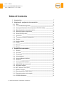
Name: C3P0
Model: SuperMicro SuperServer SYS-6012-p6 1U
Functionality: Host for the PH Server.
Description: Intel Xeon 1.8 GHz processor
256 MB RAM
1 Intel 82544 Gigabit Ethernet controller
1 Intel 82550 Ethernet controller
OS: Red Hat Linux 9.0
Figure 1: Server 6012
Notes: Only one processor installed
Specifications sheet (Annex A)
© HRTC Consortium / Clearance: Consortium
Sheet: 9 of 59
Reference: IST37652/069 Deliverable 4.7
Date: 2003-19-10 / 1.0 / Final
Name: C3P2
Model: SuperMicro SuperServer SYS-6012-p6 1U
Functionality: Host for the DataBase Server.
Description: Intel Xeon 1.8 GHz processor
256 MB RAM
1 Intel 82544 Gigabit Ethernet controller
1 Intel 82550 Ethernet controller
OS: Red Hat Linux 9.0
Notes: Only one processor installed
Specifications sheet: Annex A
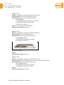
Name: C3P4
Model: SuperMicro SuperServer SYS-5012B-6 1U
Functionality: Host for the Controller.
Description: Intel Xeon 2.0 GHz processor
512 MB RAM PC133
2 Intel® 82559 Ethernet controller
OS: Red Hat Linux 9.0
Figure 2: Server 5012
Notes
Specifications sheet Annex B
Name: C3P5
Model: SuperMicro SuperServer SYS-5012B-6 1U
Functionality: Host for the Actuator Server and ICa Name Service.
Description: Intel Xeon 2.0 GHz processor
512 MB RAM PC133
2 Intel® 82559 Ethernet controller
OS: Red Hat Linux 9.0 / RTAI
Notes
Specifications sheet Annex B
© HRTC Consortium / Clearance: Consortium
Sheet: 10 of 59
Reference: IST37652/069 Deliverable 4.7
Date: 2003-19-10 / 1.0 / Final
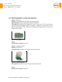
2.2 TTTechs Monitoring nodes
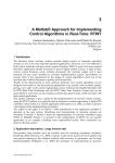
Name: TTP-Monitoring Node
Model: TTP-Monitoring Node with TTP-C2 controller (AS8202)
Functionality: The TTP-Monitoring Node is a TTP®-Ethernet gateway
node. Based on the TTP-C2 controller (AS8202), it provides powerful
facilities for monitoring and download in a TTP network. The TTP-C2
controller has synchronous (MII - 25 Mbit/s) and asynchronous (MFM - 5
Mbit/s) bus interfaces. Both of them are supported.
Description: The TTP-Monitoring Node is connected to a computer via
Ethernet (100Base-TX). It supports a standard TCP/IP connection to the
computer where TTP-Load runs. TTP-Load is used for downloading
software to a TTP cluster. TTP-View monitors an operating TTP network.
Both TTPLoad and TTP-View can communicate with the embedded
software of the TTP-Monitoring Node via standard TCP/IP Internet
protocols.
•
•
•
Motorola MPC855T PowerQUICC™ integrated communications
processor running at
80 MHz, 32-bit PowerPC® core
16 Mbytes external dynamic RAM memory (4 M x 32 bit)
8 Mbytes external Flash memory (2 M x 32 bit)
Figure 3: TTTech Monitoring node
Notes: The TTP-Monitoring Node uses an embedded real-time Linux
variant and is therefore very easily adapted for specific applications. In
addition, the TTP-Monitoring Node is equipped with a PCMCIA card
interface for user-specific applications.
Specifications sheet: Annex C.
© HRTC Consortium / Clearance: Consortium
Sheet: 11 of 59
Reference: IST37652/069 Deliverable 4.7
Date: 2003-19-10 / 1.0 / Final
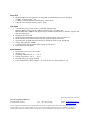
2.3 Honeywell Distributed Control System (TPS-TDC 3000)
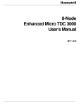
Name: Honeywell Total Plant Solution (TPS)
Model
Functionality: Distributed Control System
Description: The system is composed by:
1. A High-Performance Process Manager (HPM) controller
2. A Global User Station (GUS)
3. A History Module (HM)
4. A Network Interface Module (NIM)
5. A redundant Local Control Network (LCN)
6. A redundant Universal Control Network (UCN)
7. Several I/O cards:
a. Analog Input (AI)
b. Analog Output (AO)
c. Digital Input (DI)
d. Digital Output (DO)
e. Serial (Modbus) Interface (SI)
Figure 4: GUS and HPM components.
Notes
Specifications sheet: Annex D
© HRTC Consortium / Clearance: Consortium
Sheet: 12 of 59
Reference: IST37652/069 Deliverable 4.7
Date: 2003-19-10 / 1.0 / Final
2.4 Data Acquisition cards and modules
Name :PCI DAQ
Model: NI-DAQ 6040E (NI:National Instruments)
Functionality: Data Acquisition Card for PCI slot.
Description: Small device attached to the PCI port of a PC. It can receive
and send analog/digital signals. It needs a connector (see below) for the
signal transmission. They are used to handle the pumps and to receive the
temperature signal.
Figure 5: DAQ 6040E
Notes
Specifications sheet Annex E
Name : Connector Block
Model: NI-SCB-68
Functionality: Connects the signal from DAQ cards.
Figure 6: Connector SCB-68
Description: Shielded Input/Output connector block.
Notes
Specifications sheet: Annex F
© HRTC Consortium / Clearance: Consortium
Sheet: 13 of 59
Reference: IST37652/069 Deliverable 4.7
Date: 2003-19-10 / 1.0 / Final
Name : PCMCIA DAQ
Model: NI-6062E
Functionality: Data Acquisition Card for PCMCIA slot.
Description: Small device attached to the PCMCIA port of the TTTech
node. Used to handle pumps.
2 analog outputs; 8 digital I/O lines; two 24-bit counters; analog triggering
Figure 7: DAQ 6062E
Notes
Specifications sheet: Annex G
Name : Signal conditioning chasis
Model: NI-SC 2345
Functionality:
Description: Shielded carriers for SCC modules. It is a connector block
where signal conditioning modules are attached for the connection with
DAQ devices as temperature measures. In this project it is used with the
pt100 temperature sensor.
Notes
Specifications sheet: Annex H
Name : Temperature signal module
Model: NI-SCC-RTD01
Functionality:
Description: 2-channel module that accepts 2, 3, or 4-wire platinum RTDs.
Each channel of the NI SCC-RTD01 has an amplifier with a gain of 25 and
a 30 Hz lowpass filter. In addition, each module has a 1 mA excitation
source for one or two RTDs.
© HRTC Consortium / Clearance: Consortium
Sheet: 14 of 59
Reference: IST37652/069 Deliverable 4.7
Date: 2003-19-10 / 1.0 / Final
Figure 8: RTD01
Notes
Specifications sheet: Annex I
Name : Signal isolation module
Model: NI-SCC-AI04
Functionality:
Description: The National Instruments SCC-AI Series consists of dualchannel isolated analog input modules for the SCC signal conditioning
system. NI SCC-AI modules accept input voltages from ±50 mV to ±42 V.
They are rated for Category II, and provide safety working isolation of 300
V per module. SCC-AI modules are available with either a 4 Hz or 10 kHz
lowpass filter.
Notes
Specifications sheet: Annex J
© HRTC Consortium / Clearance: Consortium
Sheet: 15 of 59
Reference: IST37652/069 Deliverable 4.7
Date: 2003-19-10 / 1.0 / Final
2.5 Ethernet network components
Name: Ethernet communication card
Model: Intel PRO/100 S Desktop Adapter
Functionality: communication through the TCP/IP network
Description: 10/100 Mbps card
Figure 9: Ethernet card PRO 100
Notes
Specifications sheet: Annex K
Name: Ethernet communication card
Model: Intel 82550 Fast Ethernet Multifunction PCI controller
Functionality: communication through the TCP/IP network
Description: 10/100 Mbps card
Notes
Specifications sheet: Annex L
© HRTC Consortium / Clearance: Consortium
Sheet: 16 of 59
Reference: IST37652/069 Deliverable 4.7
Date: 2003-19-10 / 1.0 / Final
2.6 Serial (RS232) cable
Name: Serial cable
Model: None
Functionality: Connect the pH meter to a PC through a serial port.
Description: The pH meter can dump all the measurements to the PC via
this serial cable. The cable has a standard DB9 floating connector (male) in
the PC side, and a RJ9 connector in the pHmeter side. An electrical scheme
is provided in the specifications sheet, as well as some other useful data.
Notes
Specifications sheet
© HRTC Consortium / Clearance: Consortium
Sheet: 17 of 59
Reference: IST37652/069 Deliverable 4.7
Date: 2003-19-10 / 1.0 / Final
2.7 pH sensor
Name: pH meter
Model: Crison GLP21
Functionality: Measure the value of the pH in the reactor
Description: It is a glass electrode that generates a signal proportional to
the pH (following Nernst law). It is used in the continuous mode; that is,
each (approx.) four seconds, it automatically obtains a pH value and sends
it to a PC through the serial port.
Figure 10: pH sensor device
Notes: An special communications protocol is used, so it was necessary to
develop an special program which would be able to extract the measure
values appropriately (See the software section in this document).
Specifications sheet: Annex O
© HRTC Consortium / Clearance: Consortium
Sheet: 18 of 59
Reference: IST37652/069 Deliverable 4.7
Date: 2003-19-10 / 1.0 / Final
2.8 Temperature sensor & transmitter
Name: Temperature sensor
Model: pt100
Functionality: Measure the temperature in the reactor.
Description: Four wire temperature sensor.
Notes:
Specifications sheet: Not available
Name: Phoenix Contact temperature transducer for Pt-100
Model: MCR-PT-100-I-DC
Functionality: 4-20 mA transmitter for Pt-100 temperature sensors.
Description:
The pasive temperature sensor is connected to the
transmitter, who generates a 4-20 mA signal proportional to the
temperature.
Notes:
Specifications sheet: Annex D
© HRTC Consortium / Clearance: Consortium
Sheet: 19 of 59
Reference: IST37652/069 Deliverable 4.7
Date: 2003-19-10 / 1.0 / Final
2.9 Pumps
Name: Process pumps
Model: Micropump LG-187-0024
Functionality: Feed the reactants (acid and base) and the warm water to
the reactor.
Description: It is a positive displacement pump. These pumps are used
for low-mediums flows. It allows speed control with a signal from 0 to
5VDC. The speed range is from 500 to 4500 rpm. It has a maximum flow of
70ml/min.
Figure 11: Volumetric pumps.
Notes:
Specifications sheet: Annex Q
© HRTC Consortium / Clearance: Consortium
Sheet: 20 of 59
Reference: IST37652/069 Deliverable 4.7
Date: 2003-19-10 / 1.0 / Final
2.10 Heater module
Name: Heater
Model: Selecta Precis Term 138
Functionality: Keep a storage of hot water at a constant temperature.
Description: It is a basin with an electrical resistance and a temperature
sensor. It can be adjusted to keep the temperature at a determined value.
Figure 12: Heater module
Notes:
Specifications sheet: Not available
© HRTC Consortium / Clearance: Consortium
Sheet: 21 of 59
Reference: IST37652/069 Deliverable 4.7
Date: 2003-19-10 / 1.0 / Final
2.11 Tanks
Name: Acid Tank / Base Tank / Product Tank
Model: Not available
Functionality: Store the reactants and the products of the process.
Description: The tanks are made of glass. They have a capacity of 30liters.
Figure 13: Glass tank.
Notes:
Specifications sheet: Not available.
© HRTC Consortium / Clearance: Consortium
Sheet: 22 of 59
Reference: IST37652/069 Deliverable 4.7
Date: 2003-19-10 / 1.0 / Final
2.12 Reactor
Name: Neutralization reactor.
Model: Not available.
Functionality: Neutralize the acetic acid with the sodium hidroxide.
Description: A small glass device with its inputs fed to the top and the
output comes through a weir.
Figure 14: Glass reactor.
Notes:
Specifications sheet Not available.
© HRTC Consortium / Clearance: Consortium
Sheet: 23 of 59
Reference: IST37652/069 Deliverable 4.7
Date: 2003-19-10 / 1.0 / Final
2.13 Tubing
Name: Tubing
Model:
Functionality: Connect the different process equipment: tanks, pumps and
reactor.
Description: It is a plastic (polypropilene) tubing, semi transparent and
with a O.D.=1/8 inches.
Notes:
Specifications sheet: Annex R
© HRTC Consortium / Clearance: Consortium
Sheet: 24 of 59
Reference: IST37652/069 Deliverable 4.7
Date: 2003-19-10 / 1.0 / Final
3 Software documentation
3.1 Sensors
Name: SensorPH
Version: 2.3
Functionality: A CORBA server used to communicate with the pH meter
through the serial port. It provides a method to obtain the pH values from
other CORBA clients.
Description: SensorPH manages the serial port communications, and
retrieves the information from the pH meter, processes it, and extracts the
values. Each time the pH meter sends a new pH value, the program
updates an internal data structure with the new data. At any time a
CORBA client can call the getPH method served by SensorPH in order to
obtain the current pH value in the reactor. SensorPH can be controlled
from a local console.
Notes: The IDL interface provides a set of remote control methods that
could be used to control the program from a remote host. Those methods
are ‘empty’ in this version; although they can be implemented easily, if
necessary.
Code reference D4.4 Chapter 6 pH sensor code documentation
© HRTC Consortium / Clearance: Consortium
Sheet: 25 of 59
Reference: IST37652/069 Deliverable 4.7
Date: 2003-19-10 / 1.0 / Final
3.2 Actuators
Name:
Version:
Functionality: Send the flow signal to the DAQ.
Description: Corba server that provides methods to change the base, acid
and water flow. The actuator server receives the signal in volts between 0
and 5 for each of the 3 pumps, convert it to Comedi (DAQ driver) units
and write it in the DAQ.
Notes
Code reference D4.4 Chapter 1 actuator code documentation
© HRTC Consortium / Clearance: Consortium
Sheet: 26 of 59
Reference: IST37652/069 Deliverable 4.7
Date: 2003-19-10 / 1.0 / Final
3.3 Controllers
Name:
Version:
Functionality: Basic loop controller
Description: Takes the PH from the PH server, makes the proper
calculations and send the base and acid target flow to the actuator. In
manual operation the controller is stopped, and the signal for the DAQ
comes from the user through the HMI. It also send the variables with its
time and value tags to the Data Base. The controller implements 2 threads,
one of them as an active object.
Notes
Code reference D4.4 Chapter 2 regulator code documentation
© HRTC Consortium / Clearance: Consortium
Sheet: 27 of 59
Reference: IST37652/069 Deliverable 4.7
Date: 2003-19-10 / 1.0 / Final
3.4 Virtual objects
Name: vsensor
Version: 1.0
Functionality: Simulation of a sensor used in the intensive traffic
experiments.
Description: CORBA server program. It provides the same IDL interface
that SensorPH, but neither does real communication with a pH meter, nor
uses the serial port. It only provides a CORBA method that is used to
generate Ethernet traffic. In the intensive traffic experiment, a great
amount of this virtual sensor must be created, in order to generate a
massive data traffic
Notes: Virtual sensors are created from an auxiliary program,
“launcher_s”, that creates an specified number of vsensors named
VIRTUAL_SENSOR_X, where X is an unique number used by the
associated virtual actuator and regulator to communicate with the sensor.
Code reference D4.4 Chapter 9 virtual sensor code documentation
Name: vactuator
Version: 1.0
Functionality: Simulation of an actuator used in the intensive traffic
experiments.
Description: CORBA server program. It provides the same IDL interface
that the actuators used in PCT. It only provides CORBA methods that are
used to generate Ethernet traffic. In the intensive traffic experiment, a
great amount of this virtual actuator must be created, in order to generate
a massive data traffic.
Notes: Virtual actuators are created from an auxiliary program,
“launcher_a”, that creates an specified number of vactuators named
VIRTUAL_ACTUATOR_X, where X is an unique number used by the
associated virtual sensor and regulator to communicate with the actuator.
Code reference D4.4 Chapter 7 virtual actuator code documentation
© HRTC Consortium / Clearance: Consortium
Sheet: 28 of 59
Reference: IST37652/069 Deliverable 4.7
Date: 2003-19-10 / 1.0 / Final
Name: vregulator
Version: 1.0
Functionality: Simulation of a regulator used in the intensive traffic
experiments.
Description: CORBA client program. It uses the sensor and actuator IDL
interfaces. This program does not any real regulation work, actually. It
only calls the virtual sensor and virtual actuator methods from within an
internal loop, in order to generate Ethernet traffic. In the intensive traffic
experiment, a great amount of this virtual regulator must be created, in
order to generate a massive data traffic. The internal loop has a sleep time
that can be configured
Notes: Virtual regulators are created form an auxiliary program,
“launcher_r”, that creates an specified number of vregulator named
VIRTUAL_REGULATOR_X, where X is an unique number, used to
communicate with the associated vsensor and vactuator.
Code reference D4.4 Chapter 8 virtual regulator code documentation
© HRTC Consortium / Clearance: Consortium
Sheet: 29 of 59
Reference: IST37652/069 Deliverable 4.7
Date: 2003-19-10 / 1.0 / Final
3.5 Human Machine Interface
Name:
Version:
Functionality: Graphical user interface.
Description: Provides a graphical interface to the system. It allows the
user to change the PCT parameters, send flow signals to the pumps,
change the set points, read the variables, etc.
Notes: The HMI has been programmed using the Qt library.
Code reference D4.4 Chapter 3 HMI code documentation
© HRTC Consortium / Clearance: Consortium
Sheet: 30 of 59
Reference: IST37652/069 Deliverable 4.7
Date: 2003-19-10 / 1.0 / Final
3.6 Database
Name:
Version:
Functionality: Record the PCT variables, values and times.
Description: The data base records the variables for a future analysis.
Each variable is recorded with his unique ID, value and time (using the
NTP synchronize protocol). It uses 3 tables.
Notes: MySQL data base.
Code reference D4.4 Chapter 4 Database code documentation
© HRTC Consortium / Clearance: Consortium
Sheet: 31 of 59
Reference: IST37652/069 Deliverable 4.7
Date: 2003-19-10 / 1.0 / Final
3.7 Honeywell DCS Software
Name: TPS
Version: TPN R600 / GUS R201 / APP R101
Functionality:
Description:
Notes:
Code reference:
Configuration files (exception building) for serial modbus interface with
wrapper:
VOL PRUE
DEFAULT VOLUME ID
DRED TDC-3000
5622
{IDF NET>PRUE>SERIALI.DB, ENTITY $NM01B03( ) }
PM_BOX
$NM01B03
NTWKNUM = 01
NODENUM = 03
NODETYP = HPM
NCTLSLOT = 100
NFASTCTL = 0
NPVSLOT = 20
NFASTPV = 0
NLOGSLOT = 25
NFASTLOG = 0
NDCSLOT = 150
NFASTDC = 0
NDEVSLOT = 0
SEQPROC = 1_PU
NPMSLOT = 0
NNUMERIC = 1024
NSTRING = 0
NTIME
= 0
NARRSLOT = 001
SCANPER = 1.0000000000
SCANRATE = REG1LOG1
PKGOPT
= REDUN_2F
DISP_SIM = ON
IOMFILEA(1) = 1 IOMCARDA(1) = 03 IOMTYPE(1) =
IOREDOPT(1) = NONREDUN
IOMFILEA(2) = 1 IOMCARDA(2) = 04 IOMTYPE(2) =
IOREDOPT(2) = NONREDUN
IOMFILEA(3) = 1 IOMCARDA(3) = 05 IOMTYPE(3) =
IOREDOPT(3) = NONREDUN
IOMFILEA(4) = 1 IOMCARDA(4) = 06 IOMTYPE(4) =
IOREDOPT(4) = NONREDUN
© HRTC Consortium / Clearance: Consortium
NONE
NONE
NONE
NONE
Sheet: 32 of 59
Reference: IST37652/069 Deliverable 4.7
Date: 2003-19-10 / 1.0 / Final
IOMFILEA(5) = 1 IOMCARDA(5) = 07
IOREDOPT(5) = NONREDUN
IOMFILEA(6) = 1 IOMCARDA(6) = 08
IOREDOPT(6) = NONREDUN
IOMFILEA(7) = 1 IOMCARDA(7) = 09
IOREDOPT(7) = NONREDUN
IOMFILEA(8) = 1 IOMCARDA(8) = 10
IOREDOPT(8) = NONREDUN
IOMFILEA(9) = 1 IOMCARDA(9) = 11
IOREDOPT(9) = NONREDUN
IOMFILEA(10) = 1 IOMCARDA(10) = 12
IOREDOPT(10) = NONREDUN
IOMFILEA(11) = 1 IOMCARDA(11) = 13
IOREDOPT(11) = NONREDUN
IOMFILEA(12) = 1 IOMCARDA(12) = 14
IOREDOPT(12) = NONREDUN
IOMFILEA(13) = 1 IOMCARDA(13) = 15
IOREDOPT(13) = NONREDUN
IOMFILEA(14) = 2 IOMCARDA(14) = 03
IOREDOPT(14) = NONREDUN
IOMFILEA(15) = 2 IOMCARDA(15) = 04
IOREDOPT(15) = NONREDUN
IOMFILEA(16) = 2 IOMCARDA(16) = 05
IOREDOPT(16) = NONREDUN
IOMFILEA(17) = 2 IOMCARDA(17) = 06
IOREDOPT(17) = NONREDUN
IOMFILEA(18) = 2 IOMCARDA(18) = 07
IOREDOPT(18) = NONREDUN
IOMFILEA(19) = 2 IOMCARDA(19) = 08
IOREDOPT(19) = NONREDUN
IOMFILEA(20) = 2 IOMCARDA(20) = 09
IOREDOPT(20) = NONREDUN
IOMFILEA(21) = 2 IOMCARDA(21) = 10
IOREDOPT(21) = NONREDUN
IOMFILEA(22) = 2 IOMCARDA(22) = 11
IOREDOPT(22) = NONREDUN
IOMFILEA(23) = 2 IOMCARDA(23) = 12
IOREDOPT(23) = NONREDUN
IOMFILEA(24) = 2 IOMCARDA(24) = 13
IOREDOPT(24) = NONREDUN
IOMFILEA(25) = 2 IOMCARDA(25) = 14
IOREDOPT(25) = NONREDUN
IOMFILEA(26) = 2 IOMCARDA(26) = 15
IOREDOPT(26) = NONREDUN
IOMFILEA(27) = 3 IOMCARDA(27) = 01
IOREDOPT(27) = NONREDUN
IOMFILEA(28) = 3 IOMCARDA(28) = 02
IOREDOPT(28) = NONREDUN
IOMFILEA(29) = 3 IOMCARDA(29) = 03
IOREDOPT(29) = NONREDUN
IOMFILEA(30) = 3 IOMCARDA(30) = 04
IOREDOPT(30) = NONREDUN
© HRTC Consortium / Clearance: Consortium
IOMTYPE(5) = SI
IOMTYPE(6) = NONE
IOMTYPE(7) = NONE
IOMTYPE(8) = NONE
IOMTYPE(9) = NONE
IOMTYPE(10) = NONE
IOMTYPE(11) = NONE
IOMTYPE(12) = NONE
IOMTYPE(13) = NONE
IOMTYPE(14) = NONE
IOMTYPE(15) = NONE
IOMTYPE(16) = NONE
IOMTYPE(17) = NONE
IOMTYPE(18) = NONE
IOMTYPE(19) = NONE
IOMTYPE(20) = NONE
IOMTYPE(21) = NONE
IOMTYPE(22) = NONE
IOMTYPE(23) = NONE
IOMTYPE(24) = NONE
IOMTYPE(25) = NONE
IOMTYPE(26) = NONE
IOMTYPE(27) = NONE
IOMTYPE(28) = NONE
IOMTYPE(29) = NONE
IOMTYPE(30) = NONE
Sheet: 33 of 59
Reference: IST37652/069 Deliverable 4.7
Date: 2003-19-10 / 1.0 / Final
IOMFILEA(31) = 3 IOMCARDA(31) = 05 IOMTYPE(31)
IOREDOPT(31) = NONREDUN
IOMFILEA(32) = 3 IOMCARDA(32) = 06 IOMTYPE(32)
IOREDOPT(32) = NONREDUN
IOMFILEA(33) = 3 IOMCARDA(33) = 07 IOMTYPE(33)
IOREDOPT(33) = NONREDUN
IOMFILEA(34) = 3 IOMCARDA(34) = 08 IOMTYPE(34)
IOREDOPT(34) = NONREDUN
IOMFILEA(35) = 3 IOMCARDA(35) = 09 IOMTYPE(35)
IOREDOPT(35) = NONREDUN
IOMFILEA(36) = 3 IOMCARDA(36) = 10 IOMTYPE(36)
IOREDOPT(36) = NONREDUN
IOMFILEA(37) = 3 IOMCARDA(37) = 11 IOMTYPE(37)
IOREDOPT(37) = NONREDUN
IOMFILEA(38) = 3 IOMCARDA(38) = 12 IOMTYPE(38)
IOREDOPT(38) = NONREDUN
IOMFILEA(39) = 3 IOMCARDA(39) = 13 IOMTYPE(39)
IOREDOPT(39) = NONREDUN
IOMFILEA(40) = 3 IOMCARDA(40) = 14 IOMTYPE(40)
IOREDOPT(40) = NONREDUN
{IDF NET>PRUE>SIARRAY.DB, ENTITY SERIAL1( )}
ARRAY SERIAL1
NODETYP = HPM
PNTFORM = FULL
PTDESC
="SERIAL INTERFACE
"
KEYWORD ="
"
ASSOCDSP ="
"
UNIT
= 01
NTWKNUM = 01
NODENUM = 3
MODNUM
= 0
SLOTNUM = 1
PRIMMOD = -USERID
="
"
EXTDATA = IO_NN
IOPNUM
= 5
FTANUM
= 1
DEVADDR = 12.00
SCANPRI = HIGH
AUXDATA1 = -------AB_DATA1 = -------AUXDATA2 = -------AB_DATA2 = -------AUXDATA3 = -------AB_DATA3 = -------AUXDATA4 = 9600.100
AB_DATA4 = -------FLSTIX
= 0.000
NFLAG
= 0
NNSTIX
= 40001
NNUMERIC = 1
STRSTIX = 0.000
STRLEN
= 64
© HRTC Consortium / Clearance: Consortium
= NONE
= NONE
= NONE
= NONE
= NONE
= NONE
= NONE
= NONE
= NONE
= NONE
Sheet: 34 of 59
Reference: IST37652/069 Deliverable 4.7
Date: 2003-19-10 / 1.0 / Final
NSTRING = 0
TIMESTIX = 0.00
NTIME
= 0
SPLOCK
= OPERATOR
LFLDESC
="
"
LNNDESC
="
"
LSTRDESC ="
"
LTIMEDESC ="
"
{IDF NET>PRUE>SIARRAY.DB, ENTITY SERIAL2( ) }
ARRAY SERIAL2
NODETYP = HPM
PNTFORM = FULL
PTDESC
="SI ARRAY 2 (WRITE NUM) "
KEYWORD ="
"
ASSOCDSP ="
"
UNIT
= 01
NTWKNUM = 01
NODENUM = 3
MODNUM
= 0
SLOTNUM = 2
PRIMMOD = -USERID
="
"
EXTDATA = IO_NN
IOPNUM
= 5
FTANUM
= 1
DEVADDR = 12.00
SCANPRI = HIGH
AUXDATA1 = -------AB_DATA1 = -------AUXDATA2 = -------AB_DATA2 = -------AUXDATA3 = -------AB_DATA3 = -------AUXDATA4 = 9600.100
AB_DATA4 = -------FLSTIX
= 0.000
NFLAG
= 0
NNSTIX
= 40050
NNUMERIC = 1
STRSTIX = 0.000
STRLEN
= 64
NSTRING = 0
TIMESTIX = 0.00
NTIME
= 0
SPLOCK
= OPERATOR
LFLDESC
="
"
© HRTC Consortium / Clearance: Consortium
Sheet: 35 of 59
Reference: IST37652/069 Deliverable 4.7
Date: 2003-19-10 / 1.0 / Final
LNNDESC
="
"
LSTRDESC ="
"
LTIMEDESC ="
"
{IDF NET>PRUE>T_H013.DB, ENTITY TI_H013( )}
ANINNIM TI_H013
NODETYP = HPM
PNTFORM = COMPONNT
PTDESC
="TANK TEMPERATURE (PT100)"
EUDESC
="Degree C"
KEYWORD ="PT-100 "
ASSOCDSP ="
"
UNIT
= 01
NTWKNUM = 01
NODENUM = 03
MODNUM
= 04
SLOTNUM = 005
PNTMODTY = HLAI
SENSRTYP = 1_5_V
PVCHAR
= LINEAR
INPTDIR = DIRECT
PVEUHI
= 150
PVEULO
= 0.0
PVFORMAT = D1
PVEXEUHI = 155
PVEXEULO = -2.9
PVCLAMP = NOCLAMP
LOCUTOFF = -------TF
= 0.0
{IDF NET>PRUE>T_H013.DB, ENTITY SY_H010_3( )}
ANOUTNIM
SY_H010_3
NODETYP = HPM
PNTFORM = COMPONNT
PTDESC
="TEMPERED WATER PUMP
"
EUDESC
="% OUTPUT"
KEYWORD ="SY_H0103"
ASSOCDSP ="
"
UNIT
= 01
NTWKNUM = 01
NODENUM = 03
MODNUM
= 01
SLOTNUM = 005
PNTMODTY = AO_16
OPTDIR
= DIRECT
OPCHAR
= OFF
OPTOL
= 0.0
{IDF NET>PRUE>T_H013.DB, ENTITY HS_H010_3( ) }
© HRTC Consortium / Clearance: Consortium
Sheet: 36 of 59
Reference: IST37652/069 Deliverable 4.7
Date: 2003-19-10 / 1.0 / Final
DICMPNIM HS_H010_3
NODETYP = HPM
PNTFORM = FULL
PTDESC
="PUMP H010.3 SWITCH
EUDESC
="
"
KEYWORD ="
"
ASSOCDSP ="
"
UNIT
= 01
NTWKNUM = 01
NODENUM = 3
SLOTNUM = 5
PRIMMOD = -USERID
="----------------"
NOSTATES = 2
NODINPTS = 0
NODOPTS = 1
PVTXTOPT = OFF
STATETXT(1) ="ON
"
STATETXT(0) ="OFF
"
BOXCLR(1) = GREEN
BOXCLR(0) = YELLOW
MOMSTATE = NONE
LOGICSRC = -ST1_OP1 = ON
ST0_OP1 = OFF
DODSTN(1) = !DO03S05.SO
PULSEWTH = 1.000000
SEALOPT = NONE
MAINTOPT = OFF
NMODATTR = NONE
MODEPERM = PERMIT
OROPT
= OFF
"
{IDF NET>PRUE>T_H013.DB, ENTITY HS_H010_3P( )}
DIOUTNIM
HS_H010_3P
NODETYP = HPM
PNTFORM = COMPONNT
PTDESC
="PUMP H010.3 SWITCH POINT"
EUDESC
="
"
KEYWORD ="
"
ASSOCDSP ="
"
UNIT
= 01
NTWKNUM = 01
NODENUM = 03
MODNUM
= 03
SLOTNUM = 05
PNTMODTY = DO_32
DOTYPE
= STATUS
{IDF NET>PRUE>T_H013.DB, ENTITY TIC_H013( )}
REGCLNIM TIC_H013
NODETYP = HPM
PNTFORM = FULL
© HRTC Consortium / Clearance: Consortium
Sheet: 37 of 59
Reference: IST37652/069 Deliverable 4.7
Date: 2003-19-10 / 1.0 / Final
PTDESC
="
EUDESC
="
"
KEYWORD ="
"
ASSOCDSP ="
"
UNIT
= 01
NTWKNUM = 01
NODENUM = 3
MODNUM
= 0
SLOTNUM = 5
PRIMMOD = -USERID
="----------------"
CTLALGID = PIDERFB
PVEUHI
= 100.0000
PVEULO
= 0.000000
PVFORMAT = D1
PVSRCOPT = ALL
PVSOURCE = AUTO
OVERVAL = 25
BADCTLOP = NO_SHED
RCASOPT = NONE
NMODE
= NONE
MODEPERM = PERMIT
EXTSWOPT = NONE
SPHILM
= 100.0000
SPLOLM
= 0.000000
SPTOL
= 0.000000
SP
= 2.000000
SPOPT
= NONE
RBOPT
= NORATBI
PIDFORM = INTERACT
CTLEQN
= EQA
PVTRACK = NOTRACK
CTLACTN = REVERSE
GAINOPT = LIN
K
= 1.000000
T1
= 0.000000
T2
= 0.000000
K1
= 0.000000
NOCINPTS = 3
CISRC(1) = SERIAL1.NN(1)
CISRC(2) = SERIAL1.NN(1)
CISRC(3) = SERIAL1.NN(1)
NOCOPTS = 2
CODSTN(1) = SY_H010_3.OP
CODSTN(2) = SERIAL2.NN(1)
CVEUHI
= 100.0000
CVEULO
= 0.000000
OPHILM
= 105.0000
OPLOLM
= -5.00000
SAFEOP
= -------OPMCHLM = 0.000000
OPROCLM = -------OPTOL
= 0.000000
© HRTC Consortium / Clearance: Consortium
"
Sheet: 38 of 59
Reference: IST37652/069 Deliverable 4.7
Date: 2003-19-10 / 1.0 / Final
AUXUNIT = -BADOCOPT = OFF
OPALDB
= 5.000000
OPHITP
= -------OPLOTP
= -------PVALDB
= ONE
PVHITP
= -------PVLOTP
= -------PVROCPTP = -------PVROCNTP = -------BADPVPR = LOW
DEVHITP = -------DEVLOTP = -------ALENBST = ENABLE
© HRTC Consortium / Clearance: Consortium
Sheet: 39 of 59
Reference: IST37652/069 Deliverable 4.7
Date: 2003-19-10 / 1.0 / Final
3.8 ABACUSS II process model
Name: PCT model
Version: 1.0
Functionality: Simulate the actual PCT.
Description: A model of the real PCT (process + control) has been
developed using the modelling environment ABACUSS II [ref]. The model
is based on physical and chemical principles. The data to model the
pumps have been obtained from the vendor’s catalogue. The dissociation
constant for the acetic acid have been collected from literature.
Notes: A single model is presented in the code reference. This is the
complete model. In the experiments this model is used for operators
training. For the interaction between the simulation and the actual
controller the same model has been adapted removing the model of the
controller and redefining the connections to that sensor and actuator. This
second model is not included as is practically contained in the first one.
Code reference: As this model is developed using a simulation language it
is not included in any previous documents (D4.4 or D4.5) so the model is
described next:
################################################################
#
Model of the PCT of the HRTC Project
#
# The Process is a neutralization tank with two feeds.
#
# Feed 1 is acetic acid 0.1M
#
# Feed 2 is NaOH 0.1M
#
# The process has a pH controller.
#
# The process has a T controller
#
#
#
# --------Author: Manuel Rodríguez,DIQUIMA-ETSII-UPM---------#
# --------Last update: April 11 2003 -----------#
################################################################
DECLARE
TYPE
# Identifier
# default # lower
# upper
area
=1
: 0.0
: 10000.0
UNIT= "cm^2"
concentration
= 0.5
: 0.0
: 100.0
UNIT= "mol/l"
control_signal = 1.0
: -1.0E9
: 1.0E9
UNIT= "-"
dens_mass
= 1000.0 : 0.001
: 1500.0 UNIT= "kg/m3"
dens_mol
= 50.0
: 1.0E-5 : 150.0
UNIT= "kmol/m3"
fraction
= 0.5
: 0.0
: 1.0
UNIT= "kmol/kmol"
flow_mol
= 1000.0 : 0
: 1.0E4
UNIT= "kmol/min"
flow_vol
= 0.4
: 0.0
: 1.0E4
UNIT= "ml/s"
height
=1
: 0.0
: 1000.0 UNIT= "cm"
holdup_mol
= 2.5
: -1000.0
: 1000.0 UNIT= "mol"
molefraction
= 0.5
: 0.0
: 1.0
UNIT= "kmol/kmol"
molweight
= 75.0
: 1.0
: 200.0
UNIT= "kg/kmol"
notype
= 1.0
: -1.0E9
: 1.0E9
UNIT= "-"
percent
= 1.0
: 0.0
: 100
UNIT= "%"
pH
= 4.5
: 0.0
: 14.0
UNIT= "H+"
pressure
= 1.0
: 0.5
: 10.0
UNIT= "bar"
revolutions
= 2000
: -100
: 5000
UNIT = "rpm"
© HRTC Consortium / Clearance: Consortium
Sheet: 40 of 59
Reference: IST37652/069 Deliverable 4.7
Date: 2003-19-10 / 1.0 / Final
temperature
volume
= 25
= 10.0
:0
: 0.0
:
: 100
200
UNIT = "C"
UNIT= "l"
STREAM
Process_stream IS flow_vol , concentration , temperature
END
################################################################
MODEL Pump #This model is for the LG-187 of Micropump. Positive displacement pump.
################################################################
PARAMETER
parameter_1, Parameter_2 AS REAL #Coefficients of the linear regression
VARIABLE
Flow AS flow_vol
Concentration AS concentration
temperature AS temperature
V_in AS control_signal
speed AS revolutions
STREAM
Inlet : Flow, Concentration, temperature AS Process_stream
Output : Flow, Concentration , temperature AS Process_stream
Manipulated : V_in AS CONNECTION
EQUATION
#This equation is a relation between the motor speed and
# the flow (ml/min). The relation is obtained through a linear
# correlation made with data provided by the manufacturer.
# It is checked that the loss of pressure in the system is so slow that
# it has not to be considered in the correlation. Range is from 10ml/min(500rpm)
# to 85ml/min (4500rpm) although best results are in range 18(ml/min)(1000rpm) and
# 72ml/min (4000rpm).
# Pump Characteristic
#A relation between the control signal to the bomb, 0-5volt
# and the motor speed.
speed=1000*V_in ;
#There is a minimum value (of speed) under which the flow is ZERO.
IF speed > 50 THEN
Flow = (Parameter_1 + Parameter_2*speed)/60 ; # 60 para pasarlo a ml/s
ELSE
Flow = 0.0 ;
END
END # Pump
################################################################
MODEL PI_cont
################################################################
PARAMETER
clip
AS INTEGER
VARIABLE
# Connection:
I_in
AS control_signal
SP
AS control_signal
I_out
AS control_signal
© HRTC Consortium / Clearance: Consortium
Sheet: 41 of 59
Reference: IST37652/069 Deliverable 4.7
Date: 2003-19-10 / 1.0 / Final
# Internal:
bias
AS notype #This is the value when no error occurrs
error
AS notype
gain
AS notype
I_error
AS notype
min
AS notype
max
AS notype
C_reset
AS notype # Or integral time
value
AS notype # Output value of the controller
STREAM
Action : I_out
Reading : I_in
AS CONNECTION
AS CONNECTION
EQUATION
error
= SP - I_in;
$I_error = error;
value
= bias + gain * (error + I_error / C_reset );
# Clip if required:
IF clip = 1 THEN
IF value > max THEN
I_out = max;
ELSE IF value < min THEN
I_out = min;
ELSE
I_out = value;
END
END
ELSE
I_out = value;
END
END
################################################################
MODEL Neut_tank
################################################################
PARAMETER
ka AS
vol AS
REAL
REAL
#Equilibrium constant
VARIABLE
flow_in_base AS flow_vol
conc_base_in AS concentration
flow_in_acid AS flow_vol
conc_acid_in AS concentration
conc_acid AS concentration
conc_acetate AS concentration
mol_acid AS holdup_mol
mol_acetate AS holdup_mol
conc_H AS concentration
pH AS pH
flow_out AS flow_vol
© HRTC Consortium / Clearance: Consortium
Sheet: 42 of 59
Reference: IST37652/069 Deliverable 4.7
Date: 2003-19-10 / 1.0 / Final
flow_in_water AS flow_vol
conc_water_in AS concentration
temp_water_in AS temperature
temp_base_in AS temperature
temp_acid_in AS temperature
temperature AS temperature
STREAM
Input_water : flow_in_water, conc_water_in, temp_water_in AS Process_stream
Input_base : flow_in_base, conc_base_in , temp_base_in AS Process_stream
Input_acid : flow_in_acid, conc_acid_in, temp_acid_in AS Process_stream
Output : flow_out, conc_acid, temperature AS Process_stream
Measured : pH AS CONNECTION
Measured_T : temperature AS CONNECTION
EQUATION
conc_acid=mol_acid/vol;
conc_acetate=mol_acetate/vol;
$mol_acid=
flow_out*conc_acid/1000;
flow_in_acid*conc_acid_in/1000-flow_in_base*conc_base_in/1000-
IF mol_acid >0 THEN
$mol_acetate=flow_in_base*conc_base_in/1000-flow_out*conc_acetate/1000;
IF mol_acetate >0 THEN
conc_H=ka*conc_acid/conc_acetate;
pH=-LOG(conc_H)/LOG(10);
ELSE
pH=14+LOG(conc_acid)/LOG(10);
conc_H=10^(-14)-conc_acid;
END
ELSE
$mol_acetate=-flow_out*conc_acetate/1000;
pH= 14+LOG(conc_acid)/LOG(10);
conc_H=10^(-14)-conc_acid;
END
flow_out=flow_in_acid+flow_in_base+flow_in_water;
#Energy balance(It assumes constant Cp=1. This is because reaction heat is negligible and
# both reactants are quite diluted so liquid heat capacity from water is assumed. It also assumes
# same density for all components for the same reason. It can be more exactly formulated, although
# results will not differ significantly)
temperature
=
(flow_in_acid*temp_acid_in+flow_in_base*temp_base_in+flow_in_water*temp_water_in)/flow_out;
END
################################################################
MODEL Feed_tank
################################################################
PARAMETER
area AS REAL #area of the tank
VARIABLE
temperature AS temperature
concentration AS concentration
flow_out AS flow_vol
h AS height
STREAM
Output : flow_out, concentration , temperature AS Process_stream
© HRTC Consortium / Clearance: Consortium
Sheet: 43 of 59
Reference: IST37652/069 Deliverable 4.7
Date: 2003-19-10 / 1.0 / Final
EQUATION
$h=-flow_out/area;
END
################################################################
MODEL Product_tank
################################################################
PARAMETER
area AS REAL #area of the tank
VARIABLE
temperature AS temperature
concentration AS concentration
flow_in AS flow_vol
h AS height
STREAM
Inlet : flow_in, concentration, temperature AS Process_stream
EQUATION
$h=flow_in/area;
END
################################################################
MODEL PCT
################################################################
# Flowsheet connectivity described in this model.
PARAMETER
parameter_1, Parameter_2 AS REAL #Coefficients of the linear regression
clip
AS INTEGER
vol
AS REAL
ka
AS REAL
area AS REAL #area of the tank
UNIT
pump_base, pump_acid, pump_water AS Pump
phC AS PI_Cont
n_tank AS Neut_tank
tank_acid AS Feed_tank
tank_base AS Feed_tank
tank_water AS Feed_tank
tank_product AS Product_tank
TC AS PI_Cont
EQUATION
# Connects the controller output to the NaOH pump.
phC.Action IS pump_base.Manipulated ;
TC.Action IS pump_water.Manipulated;
pump_base.Output IS n_tank.Input_base ;
pump_acid.Output IS n_tank.Input_acid ;
pump_water.Output IS n_tank.Input_water;
n_tank.Measured IS phC.Reading ;
n_tank.Measured_T IS TC.Reading;
pump_acid.Inlet IS tank_acid.Output;
© HRTC Consortium / Clearance: Consortium
Sheet: 44 of 59
Reference: IST37652/069 Deliverable 4.7
Date: 2003-19-10 / 1.0 / Final
pump_base.Inlet IS tank_base.Output ;
pump_water.Inlet IS tank_water.Output ;
n_tank.Output IS tank_product.Inlet;
END
################################################################
SIMULATION Neutralization_tank
OPTIONS
CSVOUTPUT := TRUE;
UNIT
PCT
AS PCT
SET
WITHIN PCT DO
Parameter_2 := 0.018268899 ;
Parameter_1 := -0.219207388 ;
clip
:= 1;
ka := 1.8*0.00001;
vol := 0.2;
area := 300;
END
INPUT
WITHIN PCT DO
WITHIN pump_water DO
Concentration := 0.0 ;
temperature := 40;
END
WITHIN pump_base DO
Concentration := 0.1 ;
temperature := 20;
END
WITHIN pump_acid DO
Concentration := 0.1 ;
temperature := 20;
V_in :=1.38;
END
WITHIN phC DO
SP := 4.56;
gain :=15.5;
bias :=.55;
C_reset
:= 15.115;
max
:= 4.5;
min
:= 0;
END
WITHIN TC DO
© HRTC Consortium / Clearance: Consortium
Sheet: 45 of 59
Reference: IST37652/069 Deliverable 4.7
Date: 2003-19-10 / 1.0 / Final
SP := 25;
gain :=15.5;
bias :=.55;
C_reset
:= 15.115;
max
:= 4.5;
min
:= 0;
END
END
PRESET
WITHIN PCT DO
WITHIN pump_base DO
speed :=2000;
END
WITHIN n_tank DO
temperature :=23.8;
flow_out:= 2.1;
END
WITHIN pump_water DO
speed :=1380;
END
END
INITIAL
WITHIN PCT DO
WITHIN phC DO
I_error = 0.00;
END
WITHIN TC DO
I_error = 0.20;
END
WITHIN n_tank DO
mol_acid = 0.1;
mol_acetate = (-ka+SQRT(ka^2+4*mol_acid*ka))/2;
END
WITHIN tank_acid DO
h = 200;
END
WITHIN tank_base DO
h = 200;
END
WITHIN tank_water DO
h = 200;
END
WITHIN tank_product DO
h = 0;
END
END
SCHEDULE
SEQUENCE
CONTINUE FOR 4500.0
RESET
WITHIN PCT.phC DO
C_reset := 1.915;
END
WITHIN PCT.TC DO
C_reset := 1.915;
END
END
© HRTC Consortium / Clearance: Consortium
Sheet: 46 of 59
Reference: IST37652/069 Deliverable 4.7
Date: 2003-19-10 / 1.0 / Final
CONTINUE FOR 500.0
RESET
WITHIN PCT.pump_acid DO
concentration := 0.15;
END
END
CONTINUE FOR 2500.0
END
END
© HRTC Consortium / Clearance: Consortium
Sheet: 47 of 59
Reference: IST37652/069 Deliverable 4.7
Date: 2003-19-10 / 1.0 / Final
3.9 Simulator wrapper
Name: Simulator
Version: 1.1.
Functionality: A CORBA wrapper for the Abacuss II model of the PCT.
Description: It implements an IDL interface in order to talk to the PCT
regulator CORBA object. This interface provides two methods used to
write values to, and read values from, the Abacuss II model.
Notes:
Code reference D4.4 Chapter 10 simulator wrapper code documentation
© HRTC Consortium / Clearance: Consortium
Sheet: 48 of 59
Reference: IST37652/069 Deliverable 4.7
Date: 2003-19-10 / 1.0 / Final
3.10 NTP ethernet clock synch
Name:Network Time Protocol
Version: 4.1.1a-9
Functionality: Synchronize the PC clocks.
Description: NTP provides the protocol mechanisms to synchronize time
in to precisions in the order of nanoseconds. The protocol provisions to
specify the precision and estimated error of the
clock and the
characteristics of the reference clock to which it be synchronized.
However, the protocol itself specifies only data representation and
message formats and does not specify synchronizing algorithms or
filtering mechanisms
Notes
Code reference Not available
© HRTC Consortium / Clearance: Consortium
Sheet: 49 of 59
Reference: IST37652/069 Deliverable 4.7
Date: 2003-19-10 / 1.0 / Final
3.11 Modbus wrapper
Name
Version
Functionality: Provides a Corba wrapper to access Modbus.
Description: Implements Modbus protocol over serial line, to interface
TPS via the Serial Interface.
It implements 2 threads. The first one acts as a Corba server waiting for
requests to write or read from the modbus. The other one is an active
object to send data to the Actuator and Data Base
Notes: Based on the LibModbus library.
Code reference D4.4 Chapter 5 Modbus wrapper code documentation
© HRTC Consortium / Clearance: Consortium
Sheet: 50 of 59
Reference: IST37652/069 Deliverable 4.7
Date: 2003-19-10 / 1.0 / Final
3.12 Data Acquisition Cards drivers
Name: DAQ drivers
Version: Comedi
Functionality: Allow communication between the DAQ card and the
RTAI Linux operating system.
Description:
Notes:
Code reference:
© HRTC Consortium / Clearance: Consortium
Sheet: 51 of 59
Reference: IST37652/069 Deliverable 4.7
Date: 2003-19-10 / 1.0 / Final
3.13 Operating system and compiler
Name: Linux Red Hat
Version: 9.0
Functionality: main operating system for the TCP nodes
Description:
Notes: In the node H007.2, RTAI is also used as a module into the RedHat
base operating system.
Code reference: Not available
Name: GCC
Version: 3.2
Functionality: C and C++ compiler
Description: GCC is the GNU Compiler Collection, which currently
contains front ends for C, C++, Objective-C, Fortran, Java, and Ada, as
well as libraries for these languages (libstdc++, libgcj,...).
Notes: gcc was used through an IDE, KDevelop 2.1.5
Code reference: Not available
© HRTC Consortium / Clearance: Consortium
Sheet: 52 of 59
Reference: IST37652/069 Deliverable 4.7
Date: 2003-19-10 / 1.0 / Final
3.14 CORBA distribution
Name: ICa (Integrated Control Architecture)
Version: 1.0.1
Functionality:
•
•
•
•
Bridge the separation of an object's interface from its
implementation.
Provide, to the client, an interface to access objects.
Locate the correct object for each client request.
Transmit messages from the client to the object.
Description: ICa is composed by a set of tools and libraries targeted at
distributed intelligent computing for industrial control applications. ICa is
based in the CORBA standard (OMG, 1998) and is specifically
built for the development of industrial applications.
Notes
Code reference Not available
© HRTC Consortium / Clearance: Consortium
Sheet: 53 of 59
Reference: IST37652/069 Deliverable 4.7
Date: 2003-19-10 / 1.0 / Final
4 Evaluation
4.1 Ethernet experiments
Experiment 4.1a: CCS Ethernet loop
The experiments made with the Hub and with the Switch show that the
timing properties of the control loop are sufficient for process control,
where reaction times go from 5-10 milliseconds in the field level to 100ms
in the control network level. The loop cycle of the experiment is around
10 ms in both cases (hub and switch). The overhead imposed by using the
CORBA middleware is low and non significant.
In this experiments the actuator and the sensor have been wrapped with
the CORBA layer through the use of a PC. In the actual process industry
CORBA should go embedded in the instrument itself, taking into
advantage that the current trend is towards digital, “intelligent” devices.
This means that the footprint should be quite small as the memory of this
devices is low.
CORBA calls should be non-blocking (oneway) in order to avoid
additional latency and to get stalled when an instrument fails. (It is better
to use the “last measurement” until the device is restored or the back up
unit is on line).
CORBA implementation should allow that a client be alive even when the
server goes down, and to automatically detect when the server goes up
again and connect to it.
© HRTC Consortium / Clearance: Consortium
Sheet: 54 of 59
Reference: IST37652/069 Deliverable 4.7
Date: 2003-19-10 / 1.0 / Final
Experiment 4.2: Legacy systems integration
The possibility and characteristics of the integration of legacy sytems in
CCS are fundamentally determined by the facilities provided by vendors
of that system, not CORBA. For control purposes, in the case of the TPS
the fastest access to the controller node (HPM) is achieved via the Serial
Interface (SI).
This interface has several limitations in temporal behaviour and capacity.
For read operations:
o 80 SI connections at 1 second scan period
o 40 SI connections at ½ second scan period
o 20 SI connections at ¼ second scan period
For write requests, the number of consecutive write data requests is
limited to 16, after which, one array point read request is issued. Further,
constant writes to the serial interface (for example, a logic output) can
overload the system and degrade performance.
In conclusion, the integration of the TPS in a CCS system is possible but
constrained in capacity and scan period. Additionally, there is uncertainty
in the temporal behaviour. This allows some degree of integration in
typical process plants but is not the ideal case.
Experiment 4.5: Interaction between simulation and control
This is an off-line experiment. The integration of ABACUSS II and the
HMI and the interaction with the actual regulator has been easy using
CORBA. This has been due to the availability of the simulator as a library.
The CORBA object has wrapped the simulator interface and linked to the
library to obtain the final CORBA simulation object. The use with
commercial simulators is not so straightforward. Although the Cape Open
initiative (for open simulation using CORBA or COM) that enables the use
of components of different simulator could be a way to achieve a more
wide and generic integration between CORBA objects and COTS
simulators.
The use of real time simulation on line needs to extend CORBA to handle
the notion of time to interact with the simulator. One approach is to use
the standard RTI (HLA) for distributed simulation and extend it to real
time.
© HRTC Consortium / Clearance: Consortium
Sheet: 55 of 59
Reference: IST37652/069 Deliverable 4.7
Date: 2003-19-10 / 1.0 / Final
Experiment 4.6: Intensive data traffic
The transmissions size in the field level are traditionally small (field
networks communicate at a rate of 32kb/s) but the use of digital devices
will increase the size significantly (although being small). The control level
uses high rate transmission networks (10/100Mb/s).
The experiments performed on the Hub network show that the loop
performance degrades under a heavy load on the network. The single
collision domain makes that the latency increases as well as its variability.
The switched Ethernet can cope with the heavy load of the network but
there is a limit which is set by the capacity of the switch. A Switched
Ethernet could be used then for process control without further
consideration. But although the load in the process control network layers
is not very high it can eventually go beyond the switch capacity. As the
process control layer has to be predictable a limit has to be set, and at least
a worst case scenario is needed.
The use of CORBA with an standard wide used network as Ethernet is
appealing for the process control domain as the control layers can flatten,
costs can be reduced and information be available to any node in the
system. This poses a security problem (and possible network collapse) and
so it is critical to control the information flow between the control and
the business layer.
Experiment 4.7: Concurrent access
The experiments performed on the Hub network show a control loop
performance degradation. Latency times and its variability are increased.
The switch Ethernet experiment is also affected by the concurrency access,
although results are still good for process control.
It is clear that a priorities policy is needed for process (and any) control
systems. The regulator should have the highest priority accessing the pH
value. But for large and complex control systems where predictability (or
at least a Worst Case) is a must it is advisable to use deadlines instead of
priorities (you have to know when –in the worst case- is going to happen).
This is something that has to be implemented in CORBA.
© HRTC Consortium / Clearance: Consortium
Sheet: 56 of 59
Reference: IST37652/069 Deliverable 4.7
Date: 2003-19-10 / 1.0 / Final
CORBA has proved to handle very well requests at a very high rate as all
the elements performed (specially the pH sensor) well in this experiments.
4.2 TTP Experiments
Experiment 4.1.b: CCS TTP loop
Experiment 4.3: Sequence of events generation
Experiment 4.8: Merging networks
These experiments have not been developed as the TTP protocol has been
received after the last day of the project (September 30th ).
By that time the experiments where designed and some examples running
under the TTP network but with the IOP protocol were programmed and
tested.
The CCS TTP loop will be implemented and the results will be sent as an
addendum to this deliverable and deliverable D4.6.
Besides the lack of the experiments some conclusions can be stated about
using TTP for process control systems.
It has the advantage of being completely predictable which is very
important for any control system but:
-It is not flexible, everything has to be known in advance so a proper
design can be done. This can be useful for “not changing” systems as may
be a car or an airplane but it is not for process control where the control
configuration can change (due to many reasons, new control loop
configuration, revamping of the process, …).
-It is oriented only to time triggered events. The event time has to be
known in advance. In process control state events happen and have to be
accounted for.
-The way it operates through a broadcast of the information to all the
nodes is opposed to the CORBA client/server philosophy.
The first two drawbacks could be overcome reserving (empty) slots for
new nodes and checking at every time slot if an state event has happened.
This solves (in part) the problem but is not how TPP has been designed to
work.
© HRTC Consortium / Clearance: Consortium
Sheet: 57 of 59
Reference: IST37652/069 Deliverable 4.7
Date: 2003-19-10 / 1.0 / Final
Finally a process control system has to important elements that don’t need
hard real time requirements: the Human Machine Interface and the
Historical Module (or Database). This means that the TTP network should
be accessed from the Ethernet network. This poses the problem of a
CORBA gateway communicating two different protocols on the TTTech
Node. Other problems are related with the low memory of the nodes (as
all the variables are broadcasted this can be a problem in a network with
thousands of signals), or how “non control” functions available since
digital instruments are present can be performed on the TTP network,
functions as device information for maintenance analysis, on-line
software changes,…
4.3 Overall evaluation and conclusions of the Process Control
Testbed
CORBA is a potential element to incorporate to process control systems.
Many features make it really attractive but there are features missing as
deadlines (better than priorities) for requests. The overhead imposed is not
significant for the loop timing properties, it can cope with concurrent
requests and it works well with multiple objects (around two hundred
objects and 6000 thousand signals were alive in the intensive traffic
experiment). It is more than an alternative to OPC for process control
systems.
Due to the additional complexity, they have not been implemented in the
PCT, but fault tolerance in networks and nodes is a must in controls
systems. A redundant network and some components are the norm in
current process control.
Another issue not explored (due to the scope of the project) is
configuration. CORBA could allow the automatic detection of new nodes
in the control network, what can be seen as something good or convenient,
but it is intrinsically dangerous, since it can compromise the operation of
the system. The classic approach in process control systems implies a
configuration step where a rigid definition of the nodes and connections
are established. Maybe, some degrees of freedom or convenience in
CORBA are welcome, but control systems in plants are unlikely to not
have a well defined configuration. This means that specific components
(like configuration utilities) and specifications (like the ones that enforce
configuration) would have to be developed, or even better, become an
© HRTC Consortium / Clearance: Consortium
Sheet: 58 of 59
Reference: IST37652/069 Deliverable 4.7
Date: 2003-19-10 / 1.0 / Final
standard, if CCS is to be used by industry. It is important to distinguish
between the reconfiguration needed in process control (when a new
configuration –nodes- is needed it has to be well-defined) and the redesign
of the control system that is needed if TTP is used.
Many of those CCS components and specifications should be oriented to
safety: Safe operation of process plants is essential because they process
large quantities of toxic or explosive material and accidents can lead to
important losses in terms of human life, property and the environment.
One of the aspects is error management in a complex software system. The
classic approach has been relatively simple systems with reliable
connections. The potential flexibility of CCS is a risk that should be
minimized, perhaps leading to some loss of that flexibility. Another
necessity is the provision of diagnostic tools for CCS.
On the other hand, real-time is not very exigent in most of the process
control applications. Lag times in instruments and equipments are in the
order of, at last, hundreds of milliseconds and the networks used up to
day are much less than what we have in Ethernet.
So real time Ethernet is the best solution to use with CORBA in process
control systems as it can provide a predictable but more flexible
environment and the use of a widely used technology as it is Ethernet.
© HRTC Consortium / Clearance: Consortium
Sheet: 59 of 59
Reference: IST37652/069 Deliverable 4.7
Date: 2003-19-10 / 1.0 / Final
5
Annexes
4.4 List of Annexes
Annex A: PC 6012
Annex B: PC 5012
Annex C: TTTech Monitoring Node
Annex D: Temperature transmitter & TPS
Annex E: DAQ 6042E
Annex F: SCB 68 connector
Annex G: DAQ 6062E
Annex H: Conector SCC 2345
Annex I: RTD-01
Annex J: SCC AI-04
Annex K: Ethernet Card PRO/100
Annex L: Ethernet Card 82550
Annex O: pHmeter Crison GLP 21
Annex Q: Pumps Micropum LG-187
Annex R: Tubing
© HRTC Consortium / Clearance: Consortium
SuperServer 6012P-6
Annex A: PC 6012
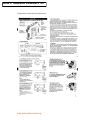
The SuperServer 6012P-6 offers the high performance of dual Xeon(tm) power in a sleek 1U rackmount configuration. Based on an Intel
E7500-chipset mainboard, the super dense 6012P-6 is making waves within the industry with such features as dual Intel® Xeon(tm)
Processors of up to 2.80GHz with a 512K L2 cache, 8GB of ECC registered DDR-200 memory and dual channel Ultra160 SCSI with three
hot-swap SCSI hard drive bays. This robust system provides build-as-you-grow scalability for Internet, ISP, and application computing
needs. Built with the superior quality and performance that has made Supermicro famous, the 6012P-6 is a density-optimized 1U
solution that will provide long-term satisfaction in a variety of applications.
**D/L PDF System Spec.
**D/L PDF Chassis Spec.
**D/L PDF Manual
SuperServer 6012P-6 (SYS-6012-P6)
Chassis
Form Factor
●
●
●
Power Supply
●
●
SCA Subsystem
●
Motherboard
●
CPU
●
●
Memory
●
●
Front Side BUS
●
Chipset
●
●
I/O Expansion
●
●
●
●
●
●
SUPER P4DPR-6GM+
Dual Intel® Xeon™ Processors up to
2.80GHz with 512K L2 cache
Up to 8GB ECC registered PC1600 DDR
SDRAM memory*
4 two-way interleaved memory modules
provide outstanding memory
performance
25 degree slots for better airflow
400MHz
Cooling
Subsystem
External Drive
Bays
Intel 82550 Ethernet controller
1 Adaptec Zero-channel SCSI RAID
Onboard I/O Devices
●
●
Other Features
●
●
●
●
4 USB ports
PS/2 keyboard and mouse ports
●
●
●
●
●
●
●
PC Health
Monitoring
●
●
●
(IPMI)1.5 (OEM optional)
ATI Rage XL 8MB PCI graphic controller
Dual Ultra DMA (UDMA/100) bus
master/EIDE channels support data
transfer rates of up to 100 MB/sec
2 Fast UART 16550 compatible serial
ports
●
●
controller (2005S) support as an optional
●
●
●
Intel® E7500
1 64-bit, 133MHz PCI-X (full length)
1 64-bit, 66MHz PCI (low profile)
1 VXB
Adaptec AIC-7899W dual channel Ultra
160(320) SCSI controller
Intel 82544 Gigabit Ethernet controller
●
●
Dimensions
●
●
●
●
●
BIOS
●
●
●
SC812 (CSE-812S-400P)
1U Rackmount
400W cold-swappable power supply (PWS0036)
Auto-switching 100/240 AC power
3 Hot-swap Ultra160 SCA 1" SCSI drive bays
(SAF-TE compliant, for one-inch high, 80-pin
SCA SCSI drives)
SCA backplane provides power, bus
termination
2 10cm heavy-duty blower fans
1 Slim 1.44MB Floppy drive
1 Slim CD-ROM
ACPI/APM power management
Onboard AOL2 (Alert-on-LAN2) controller
chip (optional)
PC'99 color-coded I/O connectors
WOL (wake-on-LAN) connector
Internal/external modem wake-up
Control of power-on mode for recovery from
AC power loss
Chassis intrusion detection
4 Onboard voltage monitors for CPU
4 Fan status
Environmental temperature monitor and
control
Chassis and CPU overheat alarm, LED
indication and control
System resource alert
Supermicro System Management utility
Width: 16.8 in.
Height: 1.7 in.
Depth: 25.6 in.
Weight: ~22 lbs. (net) ~39 lbs. (gross)
4Mb Flash ROM
BIOS rescue recovery feature
Hardware BIOS virus protection
ACPI/APM power management PnP
PXE headless support
* This product has been designed to support 2GB DIMM modules for each memory slot, but it has only been validated on 1GB memory
modules.
file:///G|/trabajo/hrtc/carlos/HRTC/SuperServer6012P-6.htm (1 de 2) [04/09/2003 0:57:08]
SuperServer 5012B-6
Annex B: PC 5012
Looking for the ideal entry-level server? Look no further! The SuperServer 5012B is your answer. Featuring a
single Intel® Pentium® 4 Processor of up to 2.80GHz, the SuperServer 5012B offers two different models to suit your needs. The
5012B-6 model offers an Adaptec AIC-7899 dual channel Ultra160 SCSI controller and two hot-swappable SCSI HD
bays for outstanding availability and scalability. If you are working within a budget, the 5012B-E model with the
IDE solution may be the one for you. Both models come with the superior performance and the product quality
Supermicro products are known for. Supermicro offers a comprehensive set of density-optimized solutions that are
proven to solve any challenges that customers encounter when they deploy servers in a racked environment.
**D/L PDF System Spec.
**D/L PDF Chassis Spec.
**D/L PDF Manual
SuperServer 5012B-6 (SYS-5012-B6)
Chassis
Form Factor
●
SC810P4 (CSE-0057-P)
●
1U Rackmount
Power Supply
●
●
●
Motherboard
●
CPU
●
Memory
●
Front Side BUS
●
Chipset
I/O Expansion
●
●
●
●
Cooling
Subsystem
External Drive
Bays
●
●
●
●
●
●
Other Features
●
●
2 Intel® 82559 Ethernet controller
●
●
ATI Rage XL 8MB PCI graphic controller
●
●
●
●
●
●
●
●
●
BIOS
Single Intel® Pentium® 4 Processor of
up to 2.80GHz
Up to 3GB PC133/100 unbuffered
SDRAM memory*
400MHz
Intel 845
1 32-bit, 33MHz PCI
Adaptec AIC-7899 dual channel Ultra160
SCSI controller
SCA Subsystem
Dual Ultra DMA (UDMA/100MB/s)
Burst data transfer rate supports UDMA
Mode 5, PIO Mode 4, ATAPI
●
Onboard I/O Devices
SUPER P4SBR
●
●
●
2 USB (Universal Serial Bus) ports
PS/2 keyboard and PS/2 mouse
connectors
2 fast UART 16550 compatible serial
ports
●
●
●
●
●
PC Health
Monitoring
●
●
1 ECP/EPP parallel port
●
1 Infrared port
1 floppy port
●
4Mb AMI FWH
BIOS rescue recovery feature
Hardware BIOS virus protection
ACPI/APM power management PnP
PXE headless support
Dimensions
●
●
●
250W power supply (PWS-0021)
Auto-switching 100/240 AC power
2 Hot-swap Ultra160 SCA 3.5" SCSI drive
bays (for one-inch high, 80-pin SCA SCSI
drives)
SCA backplane provides power, bus
termination
1 10 cm. blower fan
1 Slim 1.44MB Floppy drive
1 Slim CD-ROM
ACPI/APM power management
Onboard AOL2 (Alert-on-LAN2) controller
chip (optional)
PC'99 color-coded I/O connectors
WOL (wake-on-LAN) connector
Internal/external modem wake-up
Control of power-on mode for recovery from
AC power loss
Chassis intrusion detection
4 Onboard voltage monitors for CPU
4 Fan status
Environmental temperature monitor and
control
Chassis and CPU overheat alarm, LED
indication and control
System resource alert
Supermicro System Management utility
Width: 16.7 in.
Height: 1.7 in.
Depth: 22 in.
Weight: 17.6 lb. (Net) 22 lb. (Gross)
* This product has been designed to support three 1GB DIMMs, but it has only been validated with the 512MB memory modules.
file:///G|/trabajo/hrtc/carlos/HRTC/SuperServer5012B-6.htm (1 de 2) [04/09/2003 0:56:35]
Annex C: TTTech Monitoring Node
TTP
Monitoring Node – The TTP-Ethernet Gateway
TTP
Monitoring Node is a TTP®-Ethernet gateway node. Based on the TTP-C2 controller (AS8202), it
provides powerful facilities for monitoring and download in a TTP network. The TTP-C2 controller has
synchronous (MII – 25 Mbit/s) and asynchronous (MFM – 5 Mbit/s) bus interfaces. Both of them are
supported.
Ethernet Connection to Computer
The TTPMonitoring Node is connected to a computer via Ethernet (100Base-TX). It supports a standard
TCP/IP connection to the computer where TTPLoad runs. TTPLoad is used for downloading software to a
TTP cluster. TTPView monitors an operating TTP network. Both TTPLoad and TTPView can communicate
with the embedded software of the TTPMonitoring Node via standard TCP/IP Internet protocols.
Real-time Linux and PCMCIA Interface for User Flexibility
The TTPMonitoring Node uses an embedded real-time Linux variant and is therefore very easily adapted
for specific applications. In addition, the TTPMonitoring Node is equipped with a PCMCIA card interface
for user-specific applications.
Copyright © 2002, TTTech Computertechnik AG. All rights reserved.
Subject to changes and corrections.
Host CPU
§ Motorola MPC855T PowerQUICC™ integrated communications processor running at
80 MHz, 32-bit PowerPC® core
§ 16 Mbytes external dynamic RAM memory (4 M x 32 bit)
§ 8 Mbytes external Flash memory (2 M x 32 bit)
Interfaces
§ TTP interface (based on the TTP-C2 controller AS8202) with
MFM on RS 485 physical layer (5 Mbit/s asynchronous, 2 channels) and
MII on IEEE 802.3 100Base-TX physical layer (25 Mbit/s synchronous, 2 channels, requires hub
and star architecture)
§ PCMCIA slot of type I/II
§ Dedicated TCP/IP 100Base-TX network link to a hub, switch, or PC network card
§ Multi-channel serial communication interface (PCB-mounted connectors)
§ Serial interface on PCB-mounted connectors suitable for TTP/A, LIN, and ISO-K
§ Online debug interface (BDM)
§ Communication and application status LEDs on front panel
§ Reset button on front panel
Specifications
§ Dimensions: 220 x 145 x 26 (in mm)
§ Weight: 770 g
§ Operating temperature: 0 °C – +70 °C
§ Storage temperature: -40 °C – +85 °C
§ Housing and power supply included
§ Power requirements: input voltage 9 - 60 V DC at max. 10 Watt and max. 1.5 A
Subject to changes and corrections.
TTTech Computertechnik AG
Schoenbrunner Strasse 7
A-1040 Vienna, Austria
Tel.: +43 1 585 34 34-0
Fax: +43 1 585 34 34-90
E-mail: [email protected]
Web: www.tttech.com
TTP is a registered trademark of FTS Computertechnik Ges.m.b.H.; TTP-Monitoring Node, TTP-Load, and TTP-View are
product names of TTTech Computertechnik AG. PowerQUICC is a trademark of Motorola, Inc.; PowerPC is a registered
trademark of International Business Machines Corporation. All other trademarks are the property of their respective holders.
Annex D: Temperature transmitter & TPS
Temperature transmitter documentation
www.hardrealtimecorba.org
Sheet: 2 of 8
Reference: IST37652/008
Date: 2002-09-0 / 0.1 / Draft
© HRTC Consortium / Clearance: Consortium
Sheet: 3 of 8
Reference: IST37652/008
Date: 2002-09-0 / 0.1 / Draft
TPS: Instruments connections
© HRTC Consortium / Clearance: Consortium
Sheet: 4 of 8
Reference: IST37652/008
Date: 2002-09-0 / 0.1 / Draft
© HRTC Consortium / Clearance: Consortium
Sheet: 5 of 8
Reference: IST37652/008
Date: 2002-09-0 / 0.1 / Draft
© HRTC Consortium / Clearance: Consortium
Sheet: 6 of 8
Reference: IST37652/008
Date: 2002-09-0 / 0.1 / Draft
© HRTC Consortium / Clearance: Consortium
Sheet: 7 of 8
Reference: IST37652/008
Date: 2002-09-0 / 0.1 / Draft
© HRTC Consortium / Clearance: Consortium
Annex E: DAQ 6042E
E Series Multifunction DAQ –
250 kS/s, 12-Bit, 16 Analog Inputs
NI 604xE
NI 604xE
NI 6040E (MIO-16E-4)
PCI-MIO-16E-4
PXI-6040E
NI 6041E (AI-16E-4)
DAQCard-AI-16E-4
Real-Time
See page 184.
Driver Software
NI-DAQ
Windows 2000/NT/Me/9x
Mac OS
Analog Inputs
16 single-ended, 8 differential
channels
500 kS/s single channel scanning
250 kS/s multichannel sampling rate
250 kS/s stream-to-disk rate
12-bit resolution
Analog Output (6040E only)
2 channels, 12-bit resolution
Application Software
Digital I/O
See page 256.
†
LabVIEW
Measurement Studio
VirtualBench
Measure
Lookout
Calibration Certificate Included
8 (5 V/TTL) lines
Counter/Timers
2 up/down, 24-bit resolution
Triggering
Analog and digital
Overview
Consider the DAQCard-6062E; see page 317.
Ordering Information
NI 6040E
PCI-MIO-16E-4 ...................................................777383-01
PXI-6040E ..........................................................777484-01
NI 6041E
DAQCard-AI-16E-4 ............................................777230-01
Includes NI-DAQ for Windows 2000/NT/Me/9x and Mac OS.
Extended warranty and
value added services ..........................................page 880
Recommended Configurations
Family
NI 6040E
Accessory
SCB-68 (776844-01)
TBX-68 (777141-01)
SCB-68 (776844-01)
Cable
SH6868-EP (184749-01)
SH6868-EP (184749-01)
PSHR68-68 (777293-01)
†
Except for DAQCard-AI-16E-4
See page 334 for accessory and cable information.
1
Family
Bus
Analog
Inputs
Resolution
NI 6040E
NI 6041E
PCI, PXI/CPCI
PCMCIA
16 SE/8 DI
16 SE/8 DI
12 bits
12 bits
Sampling
Input
Rate
Range
500/250 kS/s ±0.05 to ±10 V
500/250 kS/s ±0.05 to ±10 V
1
1
Analog
Outputs
Resolution
Output
Rate
Output
Range
Digital
I/O
Counter/
Timers
Triggers
2
–
12 bits
–
1 MS/s
–
±10 V
–
8
8
2, 24-bit
2, 24-bit
Analog and Digital
Analog and Digital
Measurements
NI 6041E
DAQ Device
PCI-MIO-16E-4
PXI-6040E
DAQCard-AI-16E-4
EXPRESS
The NI 6040E and NI 6041E DAQ
CODES
devices use E Series technology to deliver
high performance and reliable data
For information or to
acquisition capabilities to meet a wide
buy products online,
visit ni.com/catalog
range of application requirements. You
and enter:
get up to 500 kS/s single-channel
pcimio16e4
(250 kS/s scanning),12-bit performance on
pxi6040e
daqcardai16e4
16 single-ended analog inputs. Depending
on your type of hard drive, these devices
can stream to disk at rates up to 250 kS/s.
These E Series DAQ devices feature
analog and digital triggering capability, as
well as two 24-bit, 20 MHz counter/timers; and 8 digital I/O lines. The
NI 6040E devices also feature two 12-bit analog outputs.
See the E Series Multifunction DAQ Overview on page 306 for a
more detailed hardware overview.
Single-channel/multichannel rate
Table 1. NI 604xE Channel, Speed, and Resolution Specifications (see page 344 for detailed specifications)
National Instruments
Tel: (512) 794-0100 • Fax: (512) 683-9300 • [email protected] • ni.com
321
Annex F: SCB-68 Connector
Multifunction DAQ Accessories
Multifunction DAQ Accessories
BNC-2090 Shielded BNC Adapter Chassis (see Figure 5)
Figure 5. BNC-2090 Shielded BNC Adapter Chassis
The BNC-2090 is a shielded, rack-mountable adapter with signal-labeled BNC
connectors, spring terminal blocks, and component locations for passive signal
conditioning. Consists of 22 BNC connectors and 28 spring terminals to simplify
connection to your analog, digital, trigger and counter/timer signals. The BNC-2090
has silk-screened component locations that you use to develop simple signal
conditioning circuits. For added flexibility, you can connect any E Series DAQ device
to the BNC-2090 from the front or rear through dual 68-pin connectors.
BNC-2090 .............................................................................................777270-01
Dimensions – 48.3 by 4.4 by 18.8 cm (19.0 by 1.7 by 7.4 in.)
CA-1000 Configurable Signal Conditioning Enclosure (see Figure 6)
The CA-1000 is a configurable enclosure that gives you maximum user-defined
connectivity and flexibility through customized panelettes. Each enclosure can
accommodate up to nine panelettes.
Dimensions – 30.7 by 25.4 by 4.3 cm (21.1 by 10 by 1.7 in.)
See page 352 for more information about the CA-1000.
DAQ and Signal Conditioning
Figure 6. CA-1000 Configurable Signal Conditioning Enclosure
TB-2705 Terminal Block for 68-pin PXI E Series Devices (see Figure 7)
The TB-2705 is a screw terminal block for PXI that works with your PXI
E Series DAQ module. It latches to the front of your PXI module with locking
screws and provides strain relief and easy access to your analog, digital, trigger
and counter/timer signals through screw terminals.
TB-2705 ................................................................................................778241-01
Dimensions – 8.43 by 10.41 by 2.03 cm (3.32 by 4.1 by 0.8 in.)
SCB-68 and SCB-100 Shielded I/O Connector Blocks (see Figure 8)
Figure 7. TB-2705 Terminal Block
Figure 8. SCB-68 and SCB-100 Shielded I/O Connector Blocks
The SCB-68 and SCB-100 are shielded I/O connector blocks for rugged, very lownoise signal termination for connecting to 68-pin or 100-pin E Series DAQ devices,
respectively. Silk-screened component locations for easy addition of simple
signal-conditioning circuitry for your analog input channels. They also include
general-purpose breadboard areas (two on the SCB-68; three on the SCB-100) as
well as an IC temperature sensor for cold-junction compensation in temperature
measurements.
SCB-68 ..................................................................................................776844-01
Dimensions – 19.5 by 15.2 by 4.5 cm (7.7 by 6.0 by 1.8 in.)
SCB-100 ................................................................................................776990-01
Dimensions – 19.5 by 15.2 by 4.5 cm (7.7 by 6.0 by 1.8 in.)
TBX-68 I/O Connector Block with DIN-Rail Mounting (see Figure 9)
The TBX-68 is a termination accessory with 68 screw terminals for easy
connection of field I/O signals to 68-pin DAQ devices. It includes one 68-pin male
connector for direct connection to 68-pin cables. The TBX-68 is mounted in a
protective plastic base with hardware for mounting on a standard DIN rail.
TBX-68 ..................................................................................................777141-01
Dimensions – 12.50 by 10.74 cm (4.92 by 4.23 in.)
Figure 9. TBX-68 I/O Connector Block
224
National Instruments • Tel: (800) 433-3488 • Fax: (512) 683-9300 • [email protected] • ni.com
Annex G: DAQ 6062E
Portable Multifunction DAQ
12 or 16-Bit, up to 1.25 MS/s, up to 16 Analog Inputs
• 16 single-ended analog inputs
• Up to 1.25 MS/s, 12-bit resolution
or 333 kS/s, 16-bit resolution
• 2 analog outputs, 12 or
16-bit resolution
• 8 digital I/O lines (5 V/TTL);
two 24-bit counter/timers
• Available for FireWire, USB,
and PCMCIA
• Digital and/or analog triggering
• NI-DAQ driver simplifies
configuration and measurements
Operating Systems
Models
Other Compatible Software
• DAQCard-6036E NEW!
• DAQCard-6062E
• DAQCard-6024E
• DAQPad-6052E for FireWire NEW!
• DAQPad-6070E for FireWire
• DAQPad-6020E for USB
Portable Multifunction DAQ
NEW
NI DAQPad-60xxE, NI DAQCard-60xxE
• Windows 2000/NT/XP/Me/9x
for DAQCards
• Windows 2000/XP/Me/98
for DAQPads
• Others such as Linux (page 187)
Recommended Software
• LabVIEW
• LabWindows/CVI
• Measurement Studio
for Visual Basic
• VI Logger
• Visual Basic
• C/C++
Driver Software (included)
• NI-DAQ
Calibration Certificate Included
See page 21
Features
National Instruments portable data acquisition products deliver the
same functionality available in PCI and PXI E Series DAQ devices
in a portable format. The DAQPad devices are hot swappable
and available in up to three different configurations. The 15 cm
enclosure is ideal for desktop, mobile, or portable applications and
features a 68-pin shielded connector. The 30 cm enclosure with
mass termination offers a low-profile package that fits under your
laptop computer. It features a 68-pin shielded connector to connect
to signals from our SCC modular signal conditioning products or
from our CA-1000 custom connectivity enclosure. The 30 cm
enclosure with BNC connectivity is ideal for applications that
require portability and quick connectivity, such as in-vehicle
automotive or aircraft testing and portable data logging.
NI DAQCards are Type II, PC Card compliant and give the same
performance as their PCI or PXI counterparts. However, their compact
design makes them ideal for applications where space constraint is an
important concern, such as in field service and research.
The NI portable DAQ devices offer a
wide range of functionality for FireWire
(IEEE 1394), USB, and PCMCIA. In
addition to 12 or 16-bit analog input and
output resolution and high sampling
rates, all devices feature two 24-bit
20 MHz counter/timers and eight digital
I/O lines.
INFO CODES
For more information,
or to order products
online visit ni.com/info
and enter:
daqcard6036e
daqcard6062e
daqcard6024e
daqpad6052e
daqpad6070e
daqpad6020e
DAQ and Signal Conditioning
Overview and Applications
BUY ONLINE!
Family
DAQCard-6036E
DAQCard-6062E
Bus
PCMCIA
PCMCIA
Analog
Inputs
16 SE/8 DI
16 SE/8 DI
Input
Resolution
16 bits
12 bits
Sampling
Rate
200 kS/s
500 kS/s
Input
Range
±0.05 to ±10 V
±0.05 to ±10 V
Analog
Output
Outputs Resolution
2
16 bits
2
12 bits
Output
Rate
1 kS/s
850 kS/s
Output
Range
±10 V
±10 V
Digital
I/O
8
8
Counter/
Timers
2, 24-bit
2, 24-bit
DAQCard-6024E
DAQPad-6052E
PCMCIA
FireWire
16 SE/8 DI
16 SE/8 DI
12 bits
16 bits
200 kS/s
333 kS/s
±0.05 to ±10 V
±0.05 to ±10 V
2
2
12 bits
16 bits
1 kS/s
333 kS/s
±10 V
±10 V
8
8
2, 24-bit
2, 24-bit
DAQPad-6070E
FireWire
16 SE/8 DI
12 bits
1.25 MS/s
±0.05 to ±10 V
2
12 bits
1 MS/s
±10 V
8
2, 24-bit
DAQPad-6020E
USB
16 SE/8 DI
12 bits
100 kS/s
±0.05 to ±10 V
2
12 bits
20 S/s
±10 V
8
2, 24-bit
Triggers
Digital
Analog,
Digital
Digital
Analog,
Digital
Analog,
Digital
Digital
Table 1. NI Portable DAQ Products
National Instruments • Tel: (800) 433-3488 • Fax: (512) 683-9300 • [email protected] • ni.com
215
Annex H: Connector SCC-2345
SCC Signal Conditioning Overview
Portable Modular DAQ Systems
SCC Signal Conditioning Overview
NI SCC
• Signal conditioning for DAQ systems
• Up to:
- 16 analog inputs
- 8 digital I/O lines
- 2 unconditioned counter/timer
I/O lines
• Measurement type and
connectivity selectable
on a per-channel basis
• Low-profile carriers for portable,
rack-mount, and desktop applications
• NI-DAQ driver software simplifies
configuration and measurement
Sensors/Signals
DAQ and Signal Conditioning
• Thermocouples
• RTDs
• Strain gauges
• Force/load/torque sensors
• Accelerometers
• Isolated voltage/current input
• Frequency input
• Lowpass filtering
• Isolated voltage/current output
• Isolated digital I/O
• Relay switching
Connectivity Options
• BNC
• Minithermocouple
• Thermocouple
• LEMO (B-series)
• MIL-Spec
• 9-pin D-Sub
• Banana jack
• SMB
• Momentary pushbutton switch
• Toggle switch
• Rocker switch
• LED
• Potentiometer
• Strain relief
Overview
National Instruments SCC provides portable, modular signal
conditioning to your DAQ system. SCC conditions a variety of analog
I/O and digital I/O signals. With this modular design, you choose your
conditioning on a per-channel basis. SCC systems offer custom
connectivity options, matching your sensor or signal connection
type. While the low-profile carrier is perfect for use with PCMCIA
DAQCards and DAQPads for portable applications, you can also use
the system for rack-mounted or desktop applications. SCC modules
works with E Series and basic multifunction DAQ devices.
SCC DAQ Systems
INFO CODES
SCC DAQ systems consist of an
For more information
SC-2345 Series shielded carrier, SCC
or to order products
online, visit ni.com/info
modules, an DAQ device, and a cable.
and enter:
Each carrier can hold up to 20 SCC
scc
modules. Conditioned analog signals
are passed directly to the inputs of the
BUY ONLINE!
DAQ device. SCC modules can also
provide up to 300 V of working
isolation to voltage and current output signals from the DAQ device.
Optically isolated digital I/O modules can condition digital lines from
the DAQ device or access them directly using the 42-pin screw
terminal mounted inside the box. Relay modules add switching to
your SCC DAQ system, and you can access analog output signals
as well as timing and triggering signals from the DAQ device using
feedthrough modules.
Figure 1. SC-2345 with Configurable Connectors
320
National Instruments • Tel: (800) 433-3488 • Fax: (512) 683-9300 • [email protected] • ni.com
Annex I: RTD-01
SCC Modules
Portable, Modular Signal Conditioning Modules
Two versions of the SCC-TC are available. The SCC-TC01 includes a
2-prong uncompensated thermocouple jack that accepts any miniature or
subminiature 2-prong male thermocouple plug. The SCC-TC02 includes a
removable screw terminal plug that includes an additional connection for
grounding thermocouple shields.
Figure 1. SCC-TC01 and SCC-TC02 Thermocouple Input Modules
(thermocouple plug not included)
NI SCC-TC Series Thermocouple Input
Model
SCC-TC01
SCC-TC02
Ch
1
1
Description
Thermocouple, spade connector
Thermocouple input
Figure 3. SCC-RTD01
Part Number
777459-03
777459-04
DAQ and Signal Conditioning
Table 1. SCC-TC Series Modules
NI SCC-RTD01 RTD Input
Model
SCC-RTD01
Ch
2
Description
2, 3, or 4-wire Pt RTD
Table 2. SCC-RTD01 Module
The National Instruments SCC-TC01 and SCC-TC02 are single-input
modules for conditioning signals from a variety of thermocouple
types, including J, K, T, B, E, N, R, and S, and millivolt inputs with a
range of ±100 mV. The SCC-TC modules include a 2 Hz lowpass
filter, an instrumentation amplifier with a gain of 100, and buffered
outputs for maximum scanning rates by the multifunction DAQ
device. The input circuitry of the SCC-TC modules also includes
high-impedance bias resistors for open-thermocouple detection as
well as handling both floating and ground-referenced
thermocouples. The SCC-TC modules include an onboard
thermistor for cold-junction compensation (See Figure 2).
When you install an SCC-TC in the SC-2345, the carrier routes the
thermocouple signal and the cold-junction signal to two input channels
of the DAQ device, channels X and X+8, respectively, where X is any
channel 0 through 7. For example, if you install the module in socket J1
of the SC-2345, the carrier routes the thermocouple signal channel 0
and the cold-junction sensor output to channel 8.
Thermocouple Source
The SCC-RTD01 is a dual-channel
INFO CODES
module that accepts 2, 3, or 4-wire
For more information
platinum RTDs. Each channel of the
or to order products
online, visit ni.com/info
SCC-RTD01 has an amplifier with a
and enter:
gain of 25 and a 30 Hz lowpass filter.
scc
In addition, the module has a
1 mA excitation source for powering
BUY ONLINE!
the RTDs.
When you install the SCC-RTD01 in
the SC-2345, the two output voltages are routed to two input
channels of the multifunction DAQ device, channels X and X+8,
where X is any channel 0 through 7. For example, if you install
the module in the J1 socket of the SC-2345, the output
voltages are routed to input channels 0 and 8 of the DAQ device
(See Figure 4).
Red
Red
E Series
Device
SCC-TC
RTD
Black
Black
Red
Red
Ref 5 V
10 M
10 k
TC+
10 k
TC10 M
+
–
2-Pole Filter/
Buffer Stage
CH(x)
RTD
Black
Black
Offset
Calibrator
SCC-RTD01
6
5
4
3
2
1
+
–
IEX (1 mA)
+
–
Ch(X )
+
–
Ch(X + 8)
4-Wire, 2 Channels
GND
Ref 5 V
4.75 k
1%
Red
AISENSE
AIGND
SCC-RTD01
RTD
5k
LM 4040
0.1%
2.5 V
+
0.1 µF
–
0.1%
10 µF
-to 5 k o+
at 25 C 16 V 0.1 µF
2.5 k
Black
Black
Red
CH(x+8)
RTD
Black
Black
NOTE: GND available on SCC-TC02 only
Figure 2. Block Diagram of the SCC-TC01 and SCC-TC02
328
Part Number
777459-18
Figure 4. Block Diagram of the SCC-RTD01
National Instruments • Tel: (800) 433-3488 • Fax: (512) 683-9300 • [email protected] • ni.com
6
5
4
3
2
1
+
–
IEX (1 mA)
+
–
Ch(X )
+
–
Ch(X + 8)
3-Wire, 2 Channels
Annex J: SCC-AI04
SCC Modules
Portable, Modular Signal Conditioning Modules
Figure 10. SCC-ACC01 Accelerometer Input module.
NI SCC-ACC01 Accelerometer Input
DAQ and Signal Conditioning
Model
SCC-ACC01
Ch
1
Description
Accelerometer Input
Part Number
777459-19
Table 4. SCC-ACC01 Accelerometer Input Module
Figure 12. SCC-AI Series Isolated Analog Input Modules
The SCC-ACC01 is a single-channel module that accepts integrated
circuit piezoelectric compatible sensors such as accelerometers and
microphones. The SCC-ACC01 has an amplifier with a gain of two, a
0.8 Hz highpass filter, and a 19 kHz 3-pole Bessel lowpass filter.
The maximum input range is ±5 V. In addition, this module has a
4 mA current source to power an integrated circuit piezoelectric
accelerometer or microphone.
When you install the SCC-ACC01 into the SC-2345, the carrier
routes the single output voltage to one input channel of the
multifunction DAQ device, channel X, where X is 0 through 7. For
example, if installed into the J1 socket of the SC-2345, the output
voltage is routed to input channel 0 of the DAQ device (See Figure 11).
NI SCC-AI Series Isolated Analog Input
SCC-ACC01
ICP
Sensor
4
3
2
1
+
–
IEX (4 mA)
AC
Coupling
+
–
19 kHz
Lowpass CH(X )
Bessel
Model
SCC-AI01
SCC-AI02
SCC-AI03
SCC-AI04
SCC-AI05
SCC-AI06
SCC-AI07
SCC-AI13
SCC-AI14
Ch
2
2
2
2
2
2
2
2
2
Input Range
±42 V
±20 V
±10 V
±5 V
±1 V
±100 mV
±50 mV
±10 V
±5 V
Bandwidth
10 kHz
10 kHz
10 kHz
10 kHz
10 kHz
10 kHz
10 kHz
4 Hz
4 Hz
Part Number
777459-20
777459-21
777459-22
777459-23
777459-24
777459-25
777459-26
777459-27
777459-28
Table 5. SCC-AI Isolated Analog Input Modules
The SCC-AI Series modules are dual-channel isolated analog input
modules for reading input voltages from ±50 mV to ±42 V. Each
channel of an SCC-AI module includes an instrumentation
amplifier, a lowpass filter, and a potentiometer for calibration.
These modules are installation rated for Category II, and provide
safety working isolation of 300 V per module.
When you install an SCC-AI module in the SC-2345, the carrier
routes the input signals to two input channels of the multifunction
DAQ device, channels X and X+8, where X is 0 through 7.
Figure 11. SCC-ACC01 Accelerometer Input Module
Signal
Source 4
+
-
SCC-AIxx
E Series Device
+
LPF
3
CH(X)
AISENSE
AIGND
2
+
-
+
LPF
1
-
Figure 13. Block Diagram of the SCC-AI Series
330
National Instruments • Tel: (800) 433-3488 • Fax: (512) 683-9300 • [email protected] • ni.com
CH(X+8)
Intel(r) PRO/100 S Desktop Adapter
Annex K: Ethernet Card PRO/100
United States Home | Select a Location
Home Computing
Products
Business
Network Connectivity
Site Map
Developer
Products
|
Contact Us |
Reseller / Provider
About Intel
Advanced Search
PRO/100 S Desktop Adapter
Features IPSec encryption offloading using an integrated security
co-processor.
Utilizes Intel® SingleDriver™ technology for compatibility across Intel®
10/100 adapters, simplifying installation and maintenance.
Product Evaluation
Program 11
Intel® Network
Adapter Selector
Security Multimedia
Presentation
Provides advanced management capabilities for easy administration.
Intel® PRO/100 S
Desktop Adapter
Data Sheet PDF
Single unit: PILA8460C3
5-pack: PILA8460C3PAK5
20-pack: PILA8460C3PAK20
80-pack: PILA8460C3PAK80
Tech Specs
Doc Library
eTesting Labs Report:
Security Adapters
Performance Comparison
22
Intel® Security Solutions
Deployment scenarios
High Performance LAN Security
Protection and performance
Encryption Offloading
Adapter offloads IPSec encryption/decryption from PC,
conserving CPU resources for greater network
performance
Intel® 82550 Fast Ethernet Controller with Integrated
Encryption Co-processor
Combines network functions and encryption offloading
into same silicon for improved performance and
reliability
Windows* 2000 Optimization, IPSec Support
Improves performance of IPSec functionality in Windows
2000 operating systems through encryption offloading
Intel® Packet Protect II Software
Adds IPSec functionality to Windows NT* and Windows*
98 systems
3DES (168bit) Encryption33
Highest level of encryption widely available for data
protection
Advanced Management Capabilities
Ease IT administration and reduce support costs
Wired for Management (WfM) 2.0 Enabled
Remote management across platforms
Wake on LAN* and Desktop Management Interface
(DMI) 2.0
Remote troubleshooting and asset management
Pre-installed Intel® Boot Agent
Deploy and upgrade PCs remotely
file:///G|/trabajo/hrtc/carlos/HRTC/pro100s_adapter.htm (1 de 2) [04/09/2003 0:55:57]
Intel(r) PRO/100 S Desktop Adapter
1
2
Tivoli* agents
Fast, easy access to management applications
ACPI Compliant
Reduced power consumption
Intel® PROSet II Utility
Windows utility for easy setup
Intel® SingleDriver™ Technology
Common set of drivers across Intel® 10/100 network
adapters simplifies setup and maintenance, and
decreases driver conflicts among new and legacy
systems
Supports All Major OSs and NOSs44
Compatible with your environment as your network
evolves
Backward Compatible
Integrates with existing Intel network adapters and
network-ready PCs with Intel® Fast Ethernet technology
US and Canada only
eTesting Labs, September 2000.
3
Unlawful to export encryption outside the U.S. or Canada except under an approved Department of
Commerce export license or applicable license exception. For more information on export restrictions, visit
www.bxa.doc.gov/encryption.
4
Go to www.intel.com/network/connectivity/resources/technologies/advanced_features.htm for the latest
OS/NOS support.
Intel and Intel SingleDriver are trademarks or registered trademarks of Intel Corporation or its subsidiaries in the
United States and other countries. Other names and brands may be claimed as the property of others.
Intel and Intel SingleDriver are trademarks or registered trademarks of Intel Corporation or its subsidiaries in the
United States and other countries. Other names and brands may be claimed as the property of others.
*Legal Information | Privacy Policy
file:///G|/trabajo/hrtc/carlos/HRTC/pro100s_adapter.htm (2 de 2) [04/09/2003 0:55:57]
©2002 Intel Corporation
Intel® 82550 Fast Ethernet Multifunction PCI/CardBus Controller
Annex L: Ethernet Card 82550
United States Home | Select a Location
Home Computing
Business Computing
Site Map
Developer
The 82550, with an integrated IP Security (IPSec) encryption engine and
Alert on LAN functionality, is Intel's premium 10/100 Mbps network
connectivity solution. It is designed for use in Network
Design Components
Design Solutions
Contact Us
| About Intel
Advanced Search
Reseller / Solutions
The Intel® 82550 Fast Ethernet Multifunction PCI/CardBus Controller is a
third generation fully integrated Fast Ethernet Media Access Controller
(MAC)/ Physical Layer (PHY) device. The MAC offers a low-cost, highperformance 10/100 Mbps LAN solution. In addition, the 82550 requires
low real estate, which is important when competing for precious board
space. The 82550's baseline functionality is equivalent to that of the
82559 with the addition of an integrated IP Security (IPSec) encryption
engine, and Alert on LAN* 2 functionality.
Product Index
|
Intel Boot Agent
Binary code for inclusion in
BIOS (8255x PXE and RPL).
Get documentation or access
design resources for this product.
Select one
Interface Cards (NICs) and PC LAN on Motherboard (LOM) designs. The 82550
combines advanced security and manageability features to provide a secure and
easily managed Fast Ethernet connectivity solution for today's networked
environment.
Related Sites
Networking &
Communications Support
The 82550 continues Intel's platform LAN technology leadership by integrating the
following features: Triple Data Encryption Standard (3DES) IPSec encryption engine,
Advanced Configuration and Power Interface (ACPI) 1.2A based power management, wake on Magic
Packet*, wake on interesting packet and advanced System Management Bus (SMB) based manageability.
The 82550 complies with Wired for Management (WfM) Specification 2.0, PC 01 and Server 00
specifications. The 82550 is pin-compatible with the 82559, allowing these designs to be upgraded.
Compare the 82550GY and 82550EY Fast Ethernet multifunction controllers and the 82559 Fast Ethernet
controller.
Enhanced IP Support
●
●
●
TCP, UDP, IPv4 checksum offload
Received checksum verification
IP Security support
Quality of Service (QoS)
●
Multiple priority transmit queues
Optimum Integration for Lowest Cost Solution
●
●
●
●
●
●
Integrated IP Security encryption engine
Integrated IEEE 802.3 10BASE-T and 100BASE-TX compatible PHY
32-bit PCI/CardBus master interface
Modem interface for combination solutions
Integrated power management functions
Thin BGA 15x15mm package
Wired for Management and Reduced Total Cost of Ownership
●
●
●
●
●
●
Wired for Management support
Integrated Alert on LAN 2 support
Advanced Configuration Power Interface and PCI power management specifications compliance
Wake on "interesting" packets and link status change support
Magic Packet support
Remote power-up support
High-Performance Networking Functions
file:///G|/trabajo/hrtc/carlos/HRTC/82550.htm (1 de 2) [04/09/2003 0:55:07]
Intel® 82550 Fast Ethernet Multifunction PCI/CardBus Controller
●
●
●
●
●
●
●
●
●
●
Early release
Chained memory structure similar to the 82559, 82558, 82557 and 82596
Improved dynamic transmit chaining with multiple priorities transmit queues
Backward compatible software to the 82559, 82558 and 82557
Full duplex support at both 10 and 100 Mbps operation
IEEE 820.3u Auto-negotiation support
3 Kbyte transmit and 3 Kbyte receive FIFOs
Fast back-to-back transmission support with minimum interframe spacing
IEEE 802.3x 100BASE-TX Flow Control support
Adaptive Technology
Low Power Features
●
●
●
●
●
Advanced Power Management (APM) capabilities
Low power +3.3 V device
Efficient dynamic standby mode
Deep power down support
Clockrun protocol support
*Legal Information | Privacy Policy
file:///G|/trabajo/hrtc/carlos/HRTC/82550.htm (2 de 2) [04/09/2003 0:55:07]
©2003 Intel Corporation
Annex O: pHmeter CRISON GLP 21
Annex Q: Pumps Micropump LG 187
Annex R: Tubing
TFE Hose Tubing
Thermoplastic
Polypropylene
Tubing
Table of Contents
Catalog
46604660
Catalog
Polypropylene
Tubing
Section B —
TFE Hose
Series PP: Laboratory Grade—FDA, NSF Listed
Series PPB: Ultraviolet Light Resistant
919/919B – Stainless Steel Wire Braid.............................................................B2
• Acid Resistant
• High Temperature
• Medium Pressures
• Chemical Resistant
• Corrosion Resistant
• Flexible
• Dimensionally Stable
How to order Parflex polypropylene tubing
Example: PP-86-0250 is 1/2" O. D. x 3/8" I. D.
919J – Stainless Steel Wire Braid ....................................................................B3
PP – 8
6 – 0250
Coil Length in feet
919U – Stainless Steel Wire Braid ...................................................................B4
I. D. of Tubing in sixteenths of an inch
O. D. of Tubing in sixteenths of an inch
Polypropylene
929/929B – Stainless Steel Wire Braid.............................................................B5
Parflex polypropylene tubing may be used at higher
temperatures and working pressures than polyethylene tubing.
Resistance to hot water and hot corrosive acids is excellent.
Polypropylene tubing will last many times longer than nylon
tubing in hot water service. Parflex polypropylene tubing is
available in white, black, or ultraviolet resistant black, and has
good resistance to vegetable oils. Parflex polypropylene tubing
has water absorption of less than .01% and has excellent
resistance to environmental stress cracking. White PP series
polypropylene meets FDA and NSF-51 requirements for food
contact and potable water. Black polypropylene FDA and NSF51 listed tubing is available upon special request. PPB series
tubing has superior ultraviolet resistance.
929BJ – Stainless Steel Wire Braid ..................................................................B6
Fitting Recommendations:
930/930B – Convoluted ....................................................................................B7
• Parker TrueSeal™ fittings
• Parker Fast & Tite® fittings
• Parker Brass Fittings available from
Brass Products Division
Otsego, Michigan
Phone (616) 694-9411
934/934B – Convoluted ....................................................................................B8
936/936B – Convoluted ....................................................................................B9
Suggested operating temperatures, depending upon conditions,
are 0°F (-18°C) to +200°F (+93°C).
939/939B – Convoluted ..................................................................................B10
Min.
Burst
Min.
Weight
Nom.
Nom.
Avg.
Working
943B – High Pressure ....................................................................................B11
Tube
O. D.
in.
Part
Number
Tube
I. D.
in.
Wall
Thick.
in.
Reel
Length
ft.
Pressure
at 73°F
psi
Pressure
at 73°F
psi
Bend
Radius
in.
lbs.
Per
100 ft.
ColorHose .......................................................................B11
950B – Heavy Duty TFE
960/960W – FEP ............................................................................................B12
PP-21-1000
PPB-21-1000
White
Black
1/8
.080
.023
1000
350
1400
1/2
0.28
PP-32-0500
PPB-32-0500
White
Black
3/16
.120
.034
500
350
1400
3/4
0.62
PP-43-0500
PPB-43-0500
White
Black
1/4
.170
.040
500
300
1200
1
1.01
PP-53-0500
PPB-53-0500
White
Black
5/16
.187
.062
500
350
1400
1-1/4
1.87
PP-64-0500
PPB-64-0500
White
Black
3/8
.250
.062
500
300
1200
1-1/4
2.35
PP-86-0250
PPB-86-0250
White
Black
1/2
.375
.062
250
225
900
2-1/2
3.28
PP-108-0100
PPB-108-0100
White
Black
5/8
.500
.062
100
175
700
4
4.22
D10
FluidConnectors
Parker Hannifin Corporation
Parflex Division
Ravenna, Ohio
B