1
SUPER
®
REMOTE_FAN_FAIL_SOCKET1
BUZZER_ENB1
OVERHEATFAIL1
A
C
A
C
FANFAIL1
SEC_J2
SEC_I2C1
SEC_J1
SEC_J0
PRI_J2
PRI_J1
PRI_J0
SEC_IPMI1
PRI_IPMI1
SEC_MODE1
BUZZER1
PRI_I2C1
L1
WWN
SAS846EL2
REV 1.01
BAR CODE
DESIGNED IN USA
WWN
SEC_EXP1
PRI_FLASH1
S_J1
SEC_FLASH1
PRI_EXP1
P_J1
1J24
R227
EC22
2
A
CA
C
5V_LED1
J25
2
PWR5
PWR3
+12V
GND
GND
GND
GND
+12V
+5V
GND
GND
+5V
+12V
GND
GND
PWR1
EC8
EC20
+12V
+12V
+5V
GND
GND
+
+5V
+12V
GND
GND
+5V
PRI_MODE1
+
+5V
PWR6
FAN2
PWR4
FAN1
PWR2
REMOTE_FAN_FAIL_SOCKET1
BUZZER_ENB1
OVERHEATFAIL1
A
C
A
C
FANFAIL1
SEC_J2
SEC_I2C1
SEC_J1
SEC_J0
PRI_J2
PRI_J1
PRI_J0
SEC_IPMI1
PRI_IPMI1
R199
SEC_MODE1
BUZZER1
R210
PRI_I2C1
L1
WWN
SAS846EL2
REV 1.01
SAS-846EL BACKPLANE
BAR CODE
DESIGNED IN USA
WWN
SEC_EXP1
PRI_FLASH1
S_J1
SEC_FLASH1
PRI_EXP1
P_J1
R227
EC22
A
CA
C
5V_LED1
J25
2
PWR5
PWR3
+12V
GND
GND
GND
GND
+5V
+12V
GND
GND
+5V
+12V
GND
GND
PWR1
EC8
EC20
+12V
+12V
+5V
GND
GND
+5V
+
+12V
GND
GND
+5V
PRI_MODE1
+
+5V
PWR6
USER'S GUIDE
PWR4
Rev. 1.0d
FAN2
PWR2
FAN1
SAS-846EL Backplane User's Guide
The information in this User’s Manual has been carefully reviewed and is believed to be accurate.
The vendor assumes no responsibility for any inaccuracies that may be contained in this document,
makes no commitment to update or to keep current the information in this manual, or to notify any
person or organization of the updates. Please Note: For the most up-to-date version of this
manual, please see our web site at www.supermicro.com.
Super Micro Computer, Inc. ("Supermicro") reserves the right to make changes to the product
described in this manual at any time and without notice. This product, including software, if any,
and documentation may not, in whole or in part, be copied, photocopied, reproduced, translated or
reduced to any medium or machine without prior written consent.
IN NO EVENT WILL SUPERMICRO BE LIABLE FOR DIRECT, INDIRECT, SPECIAL, INCIDENTAL,
SPECULATIVE OR CONSEQUENTIAL DAMAGES ARISING FROM THE USE OR INABILITY TO
USE THIS PRODUCT OR DOCUMENTATION, EVEN IF ADVISED OF THE POSSIBILITY OF
SUCH DAMAGES. IN PARTICULAR, SUPERMICRO SHALL NOT HAVE LIABILITY FOR ANY
HARDWARE, SOFTWARE, OR DATA STORED OR USED WITH THE PRODUCT, INCLUDING THE
COSTS OF REPAIRING, REPLACING, INTEGRATING, INSTALLING OR RECOVERING SUCH
HARDWARE, SOFTWARE, OR DATA.
Any disputes arising between manufacturer and customer shall be governed by the laws of Santa
Clara County in the State of California, USA. The State of California, County of Santa Clara shall
be the exclusive venue for the resolution of any such disputes. Super Micro's total liability for all
claims will not exceed the price paid for the hardware product.
California Best Management Practices Regulations for Perchlorate Materials: This Perchlorate
warning applies only to products containing CR (Manganese Dioxide) Lithium coin cells. “Perchlorate
Material-special handling may apply. See www.dtsc.ca.gov/hazardouswaste/perchlorate”
WARNING: Handling of lead solder materials used in this
product may expose you to lead, a chemical known to
the State of California to cause birth defects and other
reproductive harm.
Manual Revision 1.0d
Release Date: January 6, 2010
Unless you request and receive written permission from Super Micro Computer, Inc., you may not
copy any part of this document.
Information in this document is subject to change without notice. Other products and companies
referred to herein are trademarks or registered trademarks of their respective companies or mark
holders.
Copyright © 2010 by Super Micro Computer, Inc.
All rights reserved.
Printed in the United States of America
ii
Safety Information and Technical Specifications
Table of Contents
Contacting Supermicro ........................................................................................v
Returning Merchandise for Service....................................................................vi
Chapter 1 Safety Guidelines
1-1
ESD Safety Guidelines ................................................................................... 1-1
1-2
General Safety Guidelines .............................................................................. 1-1
1-3
An Important Note to Users ............................................................................ 1-2
1-4
Introduction to the SAS-846EL Backplane...................................................... 1-2
Chapter 2 Jumper Settings and Pin Definitions
2-1
Front Connectors and Jumpers ...................................................................... 2-1
2-2
Front Connector and Pin Definitions ............................................................... 2-2
2-3
Front Jumper Locations and Pin Definitions ................................................... 2-4
Explanation of Jumpers .................................................................................. 2-4
2-4
Rear Connectors and LED Indicators ............................................................. 2-6
Chapter 3 Dual Port and Cascading Configurations
3-1
Single and Dual Port Expanders..................................................................... 3-1
Single Ports ..................................................................................................... 3-1
Dual Ports ....................................................................................................... 3-1
3-2
Failover............................................................................................................ 3-2
Single Host Bus Adapter ................................................................................. 3-2
Single Host Bus Adapter Failover ................................................................... 3-2
Dual Host Bus Adapter .................................................................................. 3-2
Dual Host Bus Adapter Failover...................................................................... 3-2
3-3
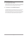
Chassis Power Card and Support Cables ...................................................... 3-3
Chassis Power Card ....................................................................................... 3-3
Connecting an Internal Host Bus Adapter to the Backplane ......................... 3-4
Supported Internal HBA Cables ...................................................................... 3-4
Connecting an External Host Bus Adapter to the Backplane ........................ 3-6
Single External Host Bus Adapter ................................................................. 3-6
Dual External Host Bus Adapter .................................................................... 3-6
Supported External HBA to Backplane Cable ................................................ 3-7
Connecting Multiple Backplanes in a Single Channel Environment ............... 3-8
Single HBA Configuration Cables ................................................................... 3-9
Connecting Multiple Backplanes in a Dual Channel Environment ............... 3-10
Dual HBA Configuration Cables .....................................................................3-11
3-4
Supported Cascading Configurations ........................................................... 3-12
iii
SAS-846EL Backplane User's Guide
Server System with Single SAS HBA ........................................................... 3-13
Dual SAS HBA and Cascaded Configuration ............................................... 3-14
Dual SAS HBA and Cascaded Configuration with Branching ...................... 3-15
iv
Safety Information and Technical Specifications
Contacting Supermicro
Headquarters
Address:
Super Micro Computer, Inc.
980 Rock Ave.
San Jose, CA 95131 U.S.A.
Tel:
+1 (408) 503-8000
Fax:
+1 (408) 503-8008
Email:
[email protected] (General Information)
[email protected] (Technical Support)
Web Site:
www.supermicro.com
Europe
Address:
Super Micro Computer B.V.
Het Sterrenbeeld 28, 5215 ML
's-Hertogenbosch, The Netherlands
Tel:
+31 (0) 73-6400390
Fax:
+31 (0) 73-6416525
Email:
[email protected] (General Information)
[email protected] (Technical Support)
[email protected] (Customer Support)
Asia-Pacific
Address:
Super Micro Computer, Inc.
4F, No. 232-1, Liancheng Rd.
Chung-Ho 235, Taipei County
Taiwan, R.O.C.
Tel:
+886-(2) 8226-3990
Fax:
+886-(2) 8226-3991
Web Site:
www.supermicro.com.tw
Technical Support:
Email:
[email protected]
Tel:
886-2-8226-1900
v
SAS-846EL Backplane User's Guide
Returning Merchandise for Service
A receipt or copy of your invoice marked with the date of purchase is required before any warranty service will be rendered. You can obtain service by calling your
vendor for a Returned Merchandise Authorization (RMA) number. When returning
to the manufacturer, the RMA number should be prominently displayed on the
outside of the shipping carton, and mailed prepaid or hand-carried. Shipping and
handling charges will be applied for all orders that must be mailed when service
is complete.
For faster service, RMA authorizations may be requested online (http://www.
supermicro.com/support/rma/).
Whenever possible, repack the backplane in the original Supermicro box, using the
original packaging materials. If these are no longer available, be sure to pack the
backplane in an anti-static bag and inside the box. Make sure that there is enough
packaging material surrounding the backplane so that it does not become damaged
during shipping.
This warranty only covers normal consumer use and does not cover damages incurred in shipping or from failure due to the alteration, misuse, abuse or improper
maintenance of products.
During the warranty period, contact your distributor first for any product problems.
vi
Safety Information and Technical Specifications
Chapter 1
Safety Guidelines
To avoid personal injury and property damage, carefully follow all the safety steps
listed below when accessing your system or handling the components.
1-1
ESD Safety Guidelines
Electrotatic Discharge (ESD) can damage electronic components. To prevent damage
to your system, it is important to handle it very carefully. The following measures are
generally sufficient to protect your equipment from ESD.
Use a grounded wrist strap designed to prevent static discharge.
•
•
Touch a grounded metal object before removing a component from the antistatic
bag.
•
Handle the backplane by its edges only; do not touch its components, peripheral
chips, memory modules or gold contacts.
•
When handling chips or modules, avoid touching their pins.
•
Put the backplane and peripherals back into their antistatic bags when not in
use.
1-2
•
•
General Safety Guidelines
Always disconnect power cables before installing or removing any components
from the computer, including the backplane.
Disconnect the power cable before installing or removing any cables from the
backplane.
•
Make sure that the backplane is securely and properly installed on the motherboard to prevent damage to the system due to power shortage.
1-1
SAS-846EL Backplane User's Guide
1-3
An Important Note to Users
All images and layouts shown in this user's guide are based upon the latest PCB
Revision available at the time of publishing. The card you have received may or
may not look exactly the same as the graphics shown in this manual.
1-4
Introduction to the SAS-846EL Backplane
The SAS-846EL backplane has been designed to utilize the most up-to-date technology available, providing your system with reliable, high-quality performance.
This manual reflects SAS-846EL Revision 1.01, the most current release available at
the time of publication. Always refer to the Supermicro Web site at www.supermicro.
com for the latest updates, compatible parts and supported configurations.
1-2
Safety Information and Technical Specifications
Chapter 2
Jumper Settings and Pin Definitions
2-1
Front Connectors and Jumpers
1 1
2
1 1
2
REMOTE_FAN_FAIL_SOCKET1
BUZZER_ENB1
OVERHEATFAIL1
A
C
A
C
FANFAIL1
SEC_J2
SEC_I2C1
SEC_J1
SEC_J0
PRI_J2
PRI_J1
PRI_J0
SEC_IPMI1
PRI_IPMI1
SEC_MODE1
BUZZER1
PRI_I2C1
L1
13
1
12
1
WWN
111
19
10
1
18
SAS846EL2
REV 1.01
BAR CODE
DESIGNED IN USA
WWN
SEC_EXP1
PRI_FLASH1
S_J1
14
SEC_FLASH1
PRI_EXP1
P_J1
15
R227
EC22
16
A
CA
15
C
5V_LED1
1J24
2
16
J25
2
PWR5
PWR3
+12V
GND
GND
GND
GND
+12V
+5V
GND
GND
+5V
+12V
GND
GND
PWR1
EC8
EC20
+12V
+12V
+5V
GND
GND
+
+5V
+12V
GND
GND
+5V
PRI_MODE1
+
+5V
PWR6
FAN2
PWR4
13
13
17 13
13
FAN1
PWR2
17
13
13
17
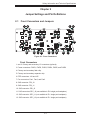
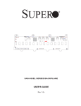
Figure 2-1: Front Connectors
BUZZER_ENB1
SEC_J2
SEC_I2C1
SEC_J1
SEC_J0
REMOTE_FAN_FAIL_SOCKET1
OVERHEATFAIL1
A
C
A
C
FANFAIL1
PRI_J2
PRI_J1
PRI_J0
SEC_IPMI1
PRI_IPMI1
R199
SEC_MODE1
BUZZER1
R210
PRI_I2C1
Front Connectors
L1
1. and 2. Primary and secondary I2C connectors (optional)
WWN
SAS846EL2
REV 1.01
BAR CODE
3. Power connectors: PWR1, PWR2, PWR3, PWR4, PWR5, and PWR6
DESIGNED IN USA
WWN
SEC_EXP1
PRI_FLASH1
S_J1
SEC_FLASH1
PRI_EXP1
P_J1
4. Primary and secondary flash chip
R227
EC22
A
CA
C
5V_LED1
5. Primary and secondary expander chip
J25
2
PWR5
PWR3
+12V
GND
GND
+5V
GND
+12V
GND
GND
+5V
+12V
GND
GND
+12V
+5V
GND
GND
+5V
+
+12V
GND
GND
+5V
PRI_MODE1
+
6. EPP connectors: J24 and J25
GND
PWR1
EC8
EC20
+12V
+5V
PWR6
FAN2
PWR4
PWR2
7. Fan connectors: Fan1, Fan2, and Fan3
8. SAS connector: PRI_J0
9. SAS connector: PRI_J1
10. SAS connector: PRI_J2
11. SAS connectors SEC_J0 (not available in EL1 single port backplane)
12. SAS connector: SEC_J1 (not available in EL1 single port backplane)
13. SAS connector: SEC_J2 (not available in EL1 single port backplane)
2-1
FAN1
14
SAS-846EL Backplane User's Guide
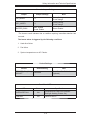
2-2
Front Connector and Pin Definitions
1. and 2. Optional Primary and Secondary
I2C Connector
Pin Definitions
2
I C Connectors
The optional I2C connectors are connected to
the CSE-PTJBOD-CB2 board and are used
to monitor the power supply status and to
control the fans. See the table on the right
for pin definitions.
Pin#
Definition
1
Data
2
Ground
3
Clock
4
No Connection
3. Backplane Main Power Connectors
The 4-pin connectors, designated PWR1,
PWR2, PWR3, PWR4, PWR5, and PWR6,
provide power to the backplane. See the
table on the right for pin definitions.
Backplane
Main Power
4-Pin Connector
Pin#
1
2 and 3
4
4. Primary and Secondary Flash Chips
The primary and secondary flash chips
enhance the backplane memory.
5. Primary and Secondary Expander Chips
This primary and secondary expander chips
allow the backplane to support dual ports,
cascading, and failover.
6. EPP Ports
The EPP ports are used for manufacturer
diagnostic purposes only.
2-2
Definition
+12V
Ground
+5V
Safety Information and Technical Specifications
7. Fan Connectors
Fan Connectors
The 3-pin connectors, designated FAN1,
FAN2, and FAN3, provide power to the
fans. See the table on the right for pin
definitions.
8 - 13. SAS Ports
The primary and secondary sets of SAS
ports provide expander features including
cascading and failover From right to left
the ports are primary 1/2/3 and secondary
1/2/3.
2-3
Pin#
Definition
1
Ground
2
+12V
3
Tachometer
SAS-846EL Backplane User's Guide
2-3
Front Jumper Locations and Pin Definitions
BUZZER_ENB1
REMOTE_FAN_FAIL_SOCKET1
OVERHEATFAIL1
FANFAIL1
SEC_MODE1
REMOTE_FAN_FAIL_SOCKET1
BUZZER_ENB1
OVERHEATFAIL1
A
C
A
C
FANFAIL1
SEC_J2
SEC_I2C1
SEC_J1
SEC_J0
PRI_J2
PRI_J1
PRI_J0
SEC_IPMI1
PRI_IPMI1
SEC_MODE1
BUZZER1
PRI_I2C1
L1
WWN
SAS846EL2
REV 1.01
BAR CODE
DESIGNED IN USA
WWN
SEC_EXP1
PRI_FLASH1
S_J1
SEC_FLASH1
PRI_EXP1
P_J1
1J24
R227
EC22
2
A
CA
C
5V_LED1
J25
2
PWR5
PWR3
+12V
GND
GND
GND
GND
+12V
+5V
GND
GND
+5V
+12V
GND
GND
GND
FAN2
PWR4
GND
+
+5V
+12V
GND
GND
+5V
PRI_MODE1
SEC_J2
SEC_J1
FAN1
PWR2
PRI_
Mode1
BUZZER_ENB1
SEC_J0
REMOTE_FAN_FAIL_SOCKET1
OVERHEATFAIL1
A
C
A
C
FANFAIL1
PRI_J2
SEC_IPMI1
R199
SEC_MODE1
BUZZER1
+12V
+5V
+
+5V
PWR6
SEC_I2C1
PWR1
EC8
EC20
+12V
PRI_J1
PRI_J0
PRI_IPMI1
R210
PRI_I2C1
L1
WWN
SAS846EL2
REV 1.01
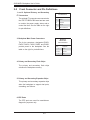
Figure 2-2: Front Jumper Locations and Pin Defimitions
BAR CODE
DESIGNED IN USA
WWN
SEC_EXP1
PRI_FLASH1
S_J1
SEC_FLASH1
PRI_EXP1
P_J1
Explanation of Jumpers
R227
EC22
A
CA
3
C
5V_LED1
To modify the operation of the backplane,
jumpers can be used to choose between
optional settings. Jumpers create shorts
between two pins to change the function
of the connector. Pin 1 is identified with
a square solder pad on the printed circuit
board. Note: On two pin jumpers, "Closed"
means the jumper is on and "Open" means
the jumper is off the pins.
J25
2
PWR5
PWR3
+12V
GND
GND
GND
GND
+5V
+12V
GND
GND
+5V
+12V
GND
GND
+12V
+5V
GND
GND
+
+5V
PWR6
PWR4
2-4
FAN2
+5V
+
+12V
2
1
PWR1
EC8
EC20
+12V
Connector
Pins
GND
GND
+5V
PRI_MODE1
FAN1
PWR2
Jumper
3
Setting
2
1
Safety Information and Technical Specifications
General Jumper Settings
Jumper
Jumper Settings
Note
PRI_MODE1
1-2
Factory Setting
Do not change
SEC_MODE1
1-2
Factory Setting
Do not change
BUZZER_ENB1
Open: Disable
Closed: Enable
Buzzer Enable*
*The buzzer sound indicates that a condition requiring immediate attention has
occurred.
The buzzer alarm is triggered by the following conditions:
1. Hard drive failure
2. Fan failure
3. System temperature over 45º Celsius.
Socket Settings
Socket
REMOTE_FAN_FAIL_
SOCKET
Socket Setting
Note
Front Panel Fan Fail indicator
(Optional)
Connected
Front Panel LEDs
LED
State
Specification
OVERHEATFAIL1
ON
Overheat/Drive Failure LED Indicator
(Red light: flashing, Buzzer: On)
FANFAIL1
ON
Failure in Fan #1
2-5
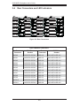
SAS-846EL Backplane User's Guide
Rear Connectors and LED Indicators
C
CA
A
C
C
CA
R250
C
ACT22
A
C
C
A
FAIL22
R252
A
ACT#20
ACT20
C
CA
A
C555
FAIL#20
FAIL20
R248
C552
C542
FAIL14
R236
C539
C547
A
SEC_SRAM2
FAIL#14
AC
CA
R243
C
ACT19
ACT#13
C
C482
ACT13
R231
ACT#19
C483
J20
FAIL#13
R224
C538
C534
FAIL#19
FAIL19
R245
C530
C529
C524
C518
A FAIL13
R233
A
C480
SAS
#19
J19
ACT#18
ACT18
ACT12
R242
F6
C
A
ACT#12
R230
C
A
R246
A
C
A
D68
C
C
FAIL#12
A
C533
SAS
#18
J18
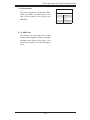
SAS Drive
Number
SAS #0
SAS/SATA HDD #0
SAS #12
SAS/SATA HDD #12
SAS #1
SAS/SATA HDD #1
SAS #13
SAS/SATA HDD #13
SAS #2
SAS/SATA HDD #2
SAS #14
SAS/SATA HDD #14
SAS #3
SAS/SATA HDD #3
SAS #15
SAS/SATA HDD #15
SAS #4
SAS/SATA HDD #4
SAS #16
SAS/SATA HDD #16
SAS #5
SAS/SATA HDD #5
SAS #17
SAS/SATA HDD #17
SAS #6
SAS/SATA HDD #6
SAS #18
SAS/SATA HDD #18
SAS #7
SAS/SATA HDD #7
SAS #19
SAS/SATA HDD #19
SAS #8
SAS/SATA HDD #8
SAS #20
SAS/SATA HDD #20
SAS #9
SAS/SATA HDD #9
SAS #21
SAS/SATA HDD #21
SAS #10
SAS/SATA HDD #10
SAS #22
SAS/SATA HDD #22
SAS #11
SAS/SATA HDD #11
SAS #23
SAS/SATA HDD #23
C537
FAIL#18
FAIL18
R244
C528
C527
C520
C523
R232
A FAIL12
C498
C494
R101
#12
FAIL#21
C
ACT#14
D70
C559
SAS
#20
D69
C488
C481
SAS #18
C511
C502
C495
A
J12
Rear
Connector
2-6
FAIL21
R249
ACT14
R234
FAIL6
SAS #12
CA
R247
C556
C514
AC
C507
C
ACT21
C549
C548
A FAIL15
R237
R225
SAS #19
D62
SAS
ACT#21
FAIL#15
AC
#13
FAIL#22
C
ACT#15
C512
C484
Rear SAS/SATA Connectors
SAS Drive
Number
ACT#22
ACT15
R235
J21
Figure 2-3: Rear Connectors
Rear
Connector
FAIL23
R253
C544
C543
C550
C540
R240
FAIL16
C546
C545
A
J13
C492
C491
R99
C410
FAIL#23
FAIL#16
C497
C496
C
J6
C554
C553
A
R238
C358
C357
D63
C508
SAS
ACT6
13
C33
C26
C28
ACT#16
C41
C40
C42 ACT16
C504
C503
C500
C499
RB1
A
R102
6
C560
SAS
#21
C490
C485
#14
L167
FAIL7
FAIL#7
C
13
12
C561
J22
C486
SAS #20
J14
SAS
C356
C355
C354
A
18
C551
C541
FAIL17
R241
C513
C509
C332
C331
ACT7
ACT#7
C
6
19
C395
C394
R89
A
SAS #6
24
R251
A
R105
18
ACT#23
FAIL#11
FAIL8
19
ACT23
R239
ACT17
C506
C505
A
C403
FAIL0
FAIL#0
AC
D32
24
R567
7
J0
TP26
SAS #13
J7
C402
C399
C389
ACT0
R88
#0
ACT#0
C
C384
C369
C366
C374
C373
C380
SAS
C510
ACT8
R103
C
A
R90
D26
SAS #0
D33
C407
F5
C501
C493
A
R106
FAIL1
J1
FAIL#9
FAIL9
C
#1
ACT#11
C519
C521
AC
R104
ACT9
R100
C103
C100
C97
C94
SAS #7
SAS
J15
L166
A
D27
#15
C557
SAS
#22
D71
C487
SAS #14
C
C375
C364
C385
C367
C370
SAS #1
C381
ACT#9
C
C421
C413
C419
J8
C417
R87
C472
C432
C428
SAS #8
J23
D72
SAS #21
SAS
D64
ACT1
R221
C526
C525
R109
R93
C477
D66
C515
C522
A
A
C474
C478
C35
C27
C45
C37
FAIL10
FAIL2
C386
C30
C44
C43
C47
C
C
J2
FAIL#10
R91
C382
SAS
#2
PRI_SRAM1
A
R107
C
ACT2
C473
C365
C376
R220
C372
C371
C469
ACT#10
C414
C422
C423
C418
C
D34
C470
C471
SAS #2
ACT10
R94
A
A
D73
C562
SAS
#23
SAS #22
C535
D65
SAS #15
SAS
J9
C531
SAS
#16
C425
C424
FAIL3
FAIL#3
AC
C433
C558
SAS #23
J17
J16
D35
C429
#9
#17
J10
C412
C415
R92
D28
C536
SAS
SAS #16
ACT#3
ACT3
C
PRI_SRAM2
C36
C46
C38
C29
C39
C32
C31
C48
R97
#10
C517
C516
R110
A
C379
C378
J3
C434
SAS
SAS #9
#3
C FAIL11
A
FAIL4
FAIL#4
C377
C368
C476
C393
SAS
C475
SAS #3
C427
C426
AC
SAS #10
D29
C383
C420
C416
ACT4
R95
C390
C400
J4
D36
C430
C532
SAS #17
J11
ACT#4
C
#4
D67
C435
FAIL#11
R98
C396
C392
C408
SAS
A
A
C401
C391
C404
R108
FAIL5
FAIL#5
AC
C5
C20
C19
C6
C14
C23
C22
C24
J5
D30
SAS #4
D37
C431
SAS #11
SAS
ACT#11
R96
ACT5
C409
TP9
#5
ACT11
C
C
C397
C387
TP8
ACT#5
D31
C405
TP5
SAS #5
C
2-4
Safety Information and Technical Specifications
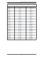
Rear LED Indicators
Rear Connector
Hard Drive Activity LED
Failure LED
SAS #0
ACT #0
FAIL #0
SAS #1
ACT #1
FAIL #1
SAS #2
ACT #2
FAIL #2
SAS #3
ACT #3
FAIL #3
SAS #4
ACT #4
FAIL #4
SAS #5
ACT #5
FAIL #5
SAS #6
ACT #6
FAIL #6
SAS #7
ACT #7
FAIL #7
SAS #8
ACT #8
FAIL #8
SAS #9
ACT #9
FAIL #9
SAS #10
ACT #10
FAIL #10
SAS #11
ACT #11
FAIL #11
SAS #12
ACT #12
FAIL #12
SAS #13
ACT #13
FAIL #13
SAS #14
ACT #14
FAIL #14
SAS #15
ACT #15
FAIL #15
SAS #16
ACT #16
FAIL #16
SAS #17
ACT #17
FAIL #17
SAS #18
ACT #18
FAIL #18
SAS #19
ACT #19
FAIL #19
SAS #20
ACT #20
FAIL #20
SAS #21
ACT #21
FAIL #21
SAS #22
ACT #22
FAIL #22
SAS #23
ACT #23
FAIL #23
2-7
SAS-846EL Backplane User's Guide
Notes
2-8
Safety Information and Technical Specifications
Chapter 3
Dual Port and Cascading Configurations
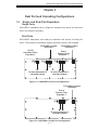
3-1
Single and Dual Port Expanders
Single Ports
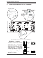
SAS-846EL1 backplanes have a single-port expander that access all twenty-four
drives and supports cascading.
Dual Ports
SAS-846EL2 backplanes have dual-port expanders that access all twenty-four
drives. These dual-port expanders support cascading, failover, and multipath.
From HBA or higher
backplane
Port B
Secondary Ports
Expander 2
J2
From HBA or higher
backplane
Port A
Primary Ports
Expander 1
J2
J1
J1
J0
J0
PRI_FLASH1
To lower backplane in
cascaded system
To lower backplane in
cascaded system
Figure 3-1: SAS-846EL2 Dual Port Configuration
From HBA or higher
backplane
Port A
Primary Ports
Expander 1
J2
J1
J0
PRI_FLASH1
To lower backplane in
cascaded system
Figure 3-2: SAS-846EL1 Single Port Configuration
3-1
SAS-846EL Backplane User's Guide
3-2
Failover
The SAS-846EL2 backplane has two expanders which allow effective failover.
Single Host Bus Adapter
SAS HBA
In a single host bus configuration, the
backplane connects to one Host Bus
Adapter (HBA).
PRI_J2
SEC_J2
SEC_J0
PRI_J1
SEC_J1
PRI_J0
WWN
Port B
Expander 2
Port A
Expander 1
J17
Figure 3-3: Single HBA
Single Host Bus Adapter
Failover
SAS HBA
PRI_J2
SEC_J2
SEC_J0
PRI_J1
SEC_J1
PRI_J0
WWN
If the expander or data path in Port A
fails, the system automatically switches
to Port B.
Port B
Expander 2
Port A
Expander 1
J17
Figure 3-4: Single HBA Failover
Dual Host Bus Adapter
SAS HBA
In a Dual Host Bus Configuration, the
backplane connects to two Host Bus
Adapters (HBA).
SAS HBA
PRI_J2
SEC_J2
SEC_J0
PRI_J1
SEC_J1
PRI_J0
WWN
Port B
Expander 2
Port A
Expander 1
J17
Figure 3-5: Dual HBA
SAS HBA
Dual Host Bus Adapter
Failover
SAS HBA
PRI_J2
SEC_J2
SEC_J0
PRI_J1
SEC_J1
PRI_J0
WWN
If the expander or data path in Port A
fails, the system automatically switches
to Port B. This maintains a full connection to all drives.
Port B
Expander 2
Port A
Expander 1
J17
Figure 3-6: Dual HBA Failover
3-2
Safety Information and Technical Specifications
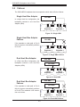
3-3
Chassis Power Card and Support Cables
Chassis Power Card
In a cascaded configuration, the first chassis includes a motherboard and at least
one Host Bus Adapter (HBA). Other servers in this enclosed system, include a
power card. This section describes the supported power card for the SAS-846
series backplane.
For more information, see the PCC-JBPWR2 power card manual. This manual can
be found at the http://www.supermicro.com or as an appendix in the SAS-846EL
chassis manual.
A
A
A
JBPWR2 REV 1.00
Figure 3-7: Chassis Power Card (Sold Separately)
Power Card
Part Number
Part Type
CSE-PTJBOD-CB1
Power card
3-3
Where Used
Allows the chassis to be in a
JBOD (Just a Bunch of Drives)
system.
SAS-846EL Backplane User's Guide
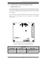
Connecting an Internal Host Bus Adapter to the
Backplane
The following section lists the most common cables used to connect the Host Bus
Adapter (HBA) to the backplane.
PRI_J2
SEC_J2
SEC_J0
PRI_J1
SEC_J1
PRI_J0
WWN
J17
HBA
(Host Bus Adapter)
Figure 3-8: Single Internal Host Bus Adapter
PRI_J2
SEC_J2
SEC_J0
PRI_J1
SEC_J1
PRI_J0
WWN
J17
HBA (Host Bus Adapter)
HBA (Host Bus Adapter)
Figure 3-9: Dual Internal Host Bus Adapter
Supported Internal HBA Cables
Use the following listed cables to create connections between the internal HBA and
SAS-846EL backplane. The cables required depend on the HBA connector.
Cable Name: iPass TO 4-lane
Part #: CBL-0117L
Length: 46 cm (18 inches)
Description: This cable has one SFF-8484 (32 pin) connector on one end and
iPass (SFF-8087/mini-sas) connector (36 pins) at the other. This cable connects
from the HBA to the SAS-846EL backplane.
3-4
Safety Information and Technical Specifications
Cable Name: iPass (mini SAS) to iPass (mini SAS)
Part #: CBL-0108L-02
Length: 39 cm (15 inches)
Part #: CBL-0109L-02
Length: 22 cm (9 inches)
Part #: CBL-0110L-02
Length: 18 cm (7 inches)
Description: This cable has an iPass (SFF-8087/mini-sas) connector (36 pins) at
each end. It connects from the HBA to the SAS-846EL backplane.
3-5
SAS-846EL Backplane User's Guide
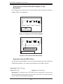
Connecting an External Host Bus Adapter to the
Backplane
This backplane supports external Host Bus Adapters. In this configuration, the HBA
and the backplane are in different physical chassis. This allows a JBOD configuration system to connect to the other system that has a HBA.
Single External Host Bus Adapter
PRI_J2
SEC_J2
SEC_J0
PRI_J1
SEC_J1
PRI_J0
WWN
J17
HBA
(Host Bus Adapter)
Power Card
CBL-0200L
External HBA Cable
Figure 3-10: Single External Host Adapter
Dual External Host Bus Adapter
PRI_J2
SEC_J2
SEC_J0
PRI_J1
SEC_J1
PRI_J0
WWN
HBA
J17
(Host Bus Adapter)
HBA
(Host Bus Adapter)
Power Card
CBL-0200L
External HBA Cables
Figure 3-11: Dual External Host Bus Adapter
3-6
Safety Information and Technical Specifications
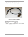
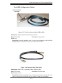
Supported External HBA to Backplane Cable
Use the following cable if your external HBA has an InfiniBand connector.
Figure 3-12: SAS InfiniBand Cable (CBL-0200L)
Cable Name: SAS InfiniBand to Mini SAS X4 1M cable, PBF
Part #: CBL-0200L
Length: 1 meter
Description: This cable has an InfiniBand connector (SFF-8470) on one end and
an SFF-8088-1X (26-pins) at the other end.
3-7
SAS-846EL Backplane User's Guide
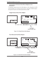
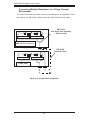
Connecting Multiple Backplanes in a Single Channel
Environment
This section describes the cables used when cascading from a single HBA. These
connections use CBL-0167L internal cables and CBL-0166L external cables.
PRI_J2
SEC_J2
SEC_J0
CBL-0167L
with Single Port Assembly
(internal cable)
PRI_J1
SEC_J1
PRI_J0
WWN
Port B Expander 2 Port A Expander 1
J17
HBA (Host Bus Adapter)
CBL-0166L
(external cable)
PRI_J2
SEC_J2
SEC_J0
PRI_J1
SEC_J1
PRI_J0
WWN
Port B Expander 2
Port A Expander 1
J17
Power Card
Figure 3-13: Single HBA Configuration
3-8
Safety Information and Technical Specifications
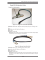
Single HBA Configuration Cables
Single Port Cable Assembly
Figure 3-14: Single Port Internal Cable (CBL-0167L)
Cable Name: SAS EL2/EL1 Backplane Cable (Internal) with 2-port Cascading Cable,
68 cm
Part #: CBL-0167L (SFF-8087 to SFF-8088 x1)
Ports: Single
Placement: Internal cable
Description: Internal cable. Connects the backplane to the Host Bus Adapter (HBA)
or external port. Used in single port environments.
Figure 3-15: External Cable (CBL-0166L)
Cable Name: SAS EL2/EL1 Cascading Cable (External), 68cm
Part #: CBL-0166L (SFF-8088 1x to SFF-8088 x1)
Ports: Single or Dual
Placement: External cable
Description: External cascading cable. Connects ports between servers. With most
connectors, use one cable for single port connections and two cables for dual port
connections.
3-9
SAS-846EL Backplane User's Guide
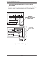
Connecting Multiple Backplanes in a Dual Channel
Environment
This section describes the cables used when cascading from dual HBAs. These
connections use CBL-0168L internal cables and CBL-0166L external cables.
PRI_J2
SEC_J2
SEC_J0
PRI_J1
SEC_J1
PRI_J0
WWN
Port B Expander 2 Port A Expander 1
J17
Cable 0168L
with Single Port Assembly
(internal cable)
HBA (Host Bus Adapter)
HBA (Host Bus Adapter)
Cable 0166L
(external cable)
PRI_J2
SEC_J2
SEC_J0
PRI_J1
SEC_J1
PRI_J0
WWN
Port B Expander 2
Port A Expander 1
J17
Power Card
Figure 3-16: Dual HBA Configuration
3-10
Safety Information and Technical Specifications
Dual HBA Configuration Cables
Dual Port Cable
Assembly
Figure 3-17: Dual Port Internal Cable (CBL-0168L)
Cable Name: SAS Dual-port Cable Assembly, 68/76cm
Part #: CBL-0168L
Ports: Dual
Placement: Internal cable
Description: Internal cascading cable. Connects the backplane to the Host Bus
Adapter (HBA) or external port. Used in dual port environments.
Figure 3-18: External Cable (CBL-0166L)
Cable Name: SAS EL2/EL1 Cascading Cable (External), 68cm
Part #: CBL-0166L
Placement: External cable
Ports: Single or Dual
Description: External cascading cable. Connects ports between servers. Use one
cable for single port connections and two cables for dual port connections.
3-11
SAS-846EL Backplane User's Guide
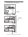
3-4
Supported Cascading Configurations
Cascading allows the system to access data at a faster rate by allowing several
backplanes to share resources to reduce latency time.
The first backplane in a cascaded system requires a motherboard and HBA. Other
servers require a power control card with no motherboard and no HBA. For more
information, see the SC846 Chassis Manual available at www.supermicro.com.
PRI_J2
SEC_J2
SEC_J0
PRI_J1
SEC_J1
PRI_J0
WWN
Port B Expander 2 Port A Expander 1
J17
Single Port Cable
Assembly
HBA (Host Bus Adapter)
Cable 0167L
(internal cable)
PRI_J2
SEC_J2
SEC_J0
Cable 0166L
(external cable)
PRI_J1
SEC_J1
PRI_J0
WWN
Port B Expander 2
Port A Expander 1
J17
Power Card
PRI_J2
SEC_J2
SEC_J0
PRI_J1
SEC_J1
PRI_J0
WWN
Port B Expander 2
Port A Expander 1
J17
Power Card
Figure 3-19: Simple Cascaded Configuration
3-12
Safety Information and Technical Specifications
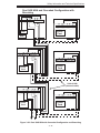
Server System with Single SAS HBA
The expanders allow horizontal branching. This configuration also applies to dual
ports.
PRI_J2
SEC_J2
SEC_J0
PRI_J2
SEC_J2
PRI_J1
SEC_J0
SEC_J1
PRI_J1
SEC_J1
PRI_J0
PRI_J0
WWN
WWN
Port A Expander 1
Port A Expander 1
J17
J17
Power Card
HBA
Cable 0167L
(internal cable)
Single Port Cable
Assembly
PRI_J2
SEC_J2
PRI_J1
PRI_J2
SEC_J2
SEC_J0
PRI_J1
SEC_J1
SEC_J0
SEC_J1
PRI_J0
PRI_J0
WWN
WWN
Port A Expander 1
Port A Expander 1
J17
J17
Power Card
Power Card
Cable 0166L
(external cable)
PRI_J2
SEC_J2
PRI_J1
PRI_J2
SEC_J2
SEC_J0
PRI_J1
SEC_J1
SEC_J0
SEC_J1
PRI_J0
PRI_J0
WWN
WWN
Port A Expander 1
Port A Expander 1
J17
J17
Power Card
Power Card
Figure 3-20: Cascaded Configuration with Horizontal Branching
3-13
SAS-846EL Backplane User's Guide
Dual SAS HBA and Cascaded Configuration
PRI_J2
SEC_J2
SEC_J0
PRI_J1
SEC_J1
PRI_J0
WWN
Port B Expander 2 Port A Expander 1
J17
HBA
Dual Port Cable
Assembly
HBA
Cable 0168L
(internal cable)
PRI_J2
SEC_J2
SEC_J0
Cable 0166L
(external cables)
PRI_J1
SEC_J1
PRI_J0
WWN
Port B Expander 2
Port A Expander 1
J17
Power Card
PRI_J2
SEC_J2
SEC_J0
PRI_J1
SEC_J1
PRI_J0
WWN
Port B Expander 2
Port A Expander 1
J17
Power Card
Figure 3-21: Dual SAS HBA with Cascaded Configuration
3-14
Safety Information and Technical Specifications
Dual SAS HBA and Cascaded Configuration with
Branching
Port B Ex. 2
Port A Ex. 1
Port B Ex. 2 Port A Ex. 1
Power
Card
HBA
HBA
Port B Ex. 2
Port A Ex. 1
Port B Ex. 2 Port A Ex. 1
Power
Card
Power
Card
Cable 0166L
(external cable)
Port B Ex. 2
Port A Ex. 1
Port B Ex. 2 Port A Ex. 1
Power
Card
Power
Card
Figure 3-22: Dual SAS HBA with Cascaded Configuration and Branching
3-15
SAS-846EL Backplane User's Guide
Disclaimer (cont.)
The products sold by Supermicro are not intended for and will not be used in life support systems, medical equipment, nuclear facilities or systems, aircraft, aircraft devices,
aircraft/emergency communication devices or other critical systems whose failure to perform be reasonably expected to result in significant injury or loss of life or catastrophic
property damage. Accordingly, Supermicro disclaims any and all liability, and should
buyer use or sell such products for use in such ultra-hazardous applications, it does so
entirely at its own risk. Furthermore, buyer agrees to fully indemnify, defend and hold
Supermicro harmless for and against any and all claims, demands, actions, litigation,
and proceedings of any kind arising out of or related to such ultra-hazardous use or
sale.
3-16