1
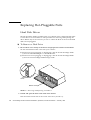
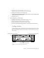
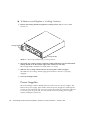
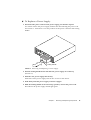
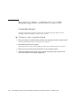
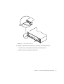
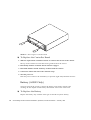
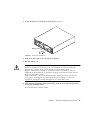
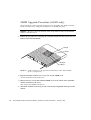
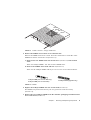
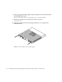
CHAPTER
3
Removing and Replacing
Components
The Sun StorEdge A1000 and D1000 systems contain easy access components, some
of which are hot-pluggable and some of which must be replaced with the power off.
Hot-pluggable Parts
■
Hard Disk Drives
■
Cooling Canisters
■
Power Supplies
Replaceable with Power Off
■
Sun StorEdge D1000 controller board
■
Sun StorEdge A1000 controller board
■
Sun StorEdge A1000 Battery
■
Sun StorEdge A1000 SIMMs
21
Replacing Hot-Pluggable Parts
Hard Disk Drives
The Sun StorEdge A1000 or D1000 system you ordered comes configured with either
1.6-inch drives or one-inch drives. The procedure for removing and replacing the
drives differs only in the software you use to control the disks. In all cases the hard
disks are hot-pluggable.
▼ To Remove a Disk Drive
1. Be sure there is no activity to the drives and prepare the software environment.
See the documentation that came with your software.
■
Instructions for hot plugging or unplugging a disk in the Sun StorEdge A1000
system are in RAID Manager 6.1.1 documentation.
■
Instructions for hot plugging or unplugging a disk in the Sun StorEdge D1000
system are in Sun StorEdge D1000 Storage Guide.
Arrow
Button Latch
FIGURE 3-1
Removing and Replacing a Disk Drive
2. Unlock and open the door at the front of the chassis.
Push down the button latch at the center of the door ( FIGURE 3-1).
22
Sun StorEdge A1000 and D1000 Installation, Operations, and Service Manual • February 1998
3. Unlatch the drive bracket handle to release it ( FIGURE 3-1).
Push down in the direction of the arrow to release the latch.
4. Pull the bracket handle out and swing it open.
5. Continue to pivot the disk drive bracket handle against the chassis, applying mild
pressure until the drive disconnects.
6. Slide the drive out
▼ To Replace a Disk Drive
1. Hold the locking handle on the disk drive open ( FIGURE 3-1).
2. Slide the replacement disk drive into the vacant slot.
3. Gently push the drive until the locking handle engages.
4. Close the locking handle handle completely, using gentle downward pressure.
Cooling Canisters
The Sun StorEdge A1000 or D1000 comes with two cooling canisters, each of which
contains two blowers. If any of the blowers fails, the LED on the back of the system
lights amber, indicating which blower has failed. To replace a blower, replace the
entire canister.
Cooling Canister Locking Handles
Cooling Canister Locking Handles
Power Supply Locking Handles
FIGURE 3-2
Rear of Sun StorEdge A1000 System
Chapter 3
Removing and Replacing Components
23
▼ To Remove and Replace a Cooling Canister
1. Release the locking handle and pull the cooling canister out ( FIGURE 3-2 and
FIGURE 3-3).
Locking Handle
Locking Handle
FIGURE 3-3
Removing and Replacing a Cooling Canister
2. Orient the new cooling canister so that the round intake holes face inward and the
locking handle is on the outside edge of the canister on each side.
The locking handle should face inward when it is closed.
3. Slide the new cooling canister into the slot and push it until it engages.
The LEDs for the cooling canister light green when the connector is properly
engaged.
4. Close the locking handle.
Power Supplies
The Sun StorEdge A1000 or D1000 enclosure comes with two power supplies. The
LED on the power supply lights amber when the power supply fails. Although the
system can run well with only one power supply, the faulty one should be replaced
in case the good one goes bad. You can replace a failed or failing power supply
without turning the system off.
24
Sun StorEdge A1000 and D1000 Installation, Operations, and Service Manual • February 1998
▼ To Replace a Power Supply
1. Disconnect the power cord from the power supply you intend to replace.
You cannot remove the power supply without first disconnecting the power cord.
See FIGURE 3-2. and FIGURE 3-3 for the positions of the power connector and locking
handle.
Locking Handle
FIGURE 3-4
Removing and Replacing a Power Supply
2. Pull the locking handle down and slide the power supply out of the bay
(FIGURE 3-4).
3. Slide the new power supply into the bay.
Small rails on the power supply base fit into cut-outs in the chassis.
4. Push firmly until the power supply connector engages.
5. With the locking handle in the closed (up) position, connect the power cord.
The LED for the power supply should light green.
Chapter 3
Removing and Replacing Components
25
Replacing Parts with the Power Off
Controller Board
You must turn off the power to replace the controller board in either the Sun
StorEdge A1000 and D1000 versions of the system.
▼ To Remove the Controller Board
1. Stop the software communication with the Sun StorEdge A1000 or D1000 system.
See the documentation that came with your software.
2. Turn off the power to the system.
Push the power switch to the standby position. Press the left side of the switch.
3. Remove the SCSI cables and terminators on the controller board.
4. Attach an antistatic wrist strap to the exposed metal part of the chassis at the
center post between the power supply bays.
26
Sun StorEdge A1000 and D1000 Installation, Operations, and Service Manual • February 1998
FIGURE 3-5
Controller Board Levers
5. Slide the controller board canister out and set it on an antistatic mat.
a. Use the levers at each side to release the controller board.
b. Hold the levers to slide the canister out.
Chapter 3
Removing and Replacing Components
27
FIGURE 3-6
Removing the Controller Board
▼ To Replace the Controller Board
1. Slide the replacement controller board in its canister into the slot in the chassis.
The top of the canister has rails that fit into guide hooks in the chassis.
2. Push firmly until the controller board connector engages.
3. Push both handles inward until they are flush with the canister.
4. Connect the cables and remove the antistatic strap.
5. Turn the power on.
Push the power switch to the momentary on position (right side) and then release it.
Battery (A1000 Only)
You must turn off the power to replace the battery. Note all the cautions and
warnings in this chapter and the safety information at the front of the book.
▼ To Replace the Battery
Replace the battery only with the same type of Sun Microsystems battery.
28
Sun StorEdge A1000 and D1000 Installation, Operations, and Service Manual • February 1998
1. Locate the battery on the back of the unit. See FIGURE 3-2.
Battery Catch
FIGURE 3-7
Removing the Battery
2. Push down the catch on the outside of the battery.
3. Pull the battery out.
Caution – There is a sealed lead acid battery in Sun StorEdge A1000 units. There is
danger of explosion if the battery pack is mishandled or incorrectly replaced.
Replace only with the same type of Sun Microsystems battery pack.
Dispose of the battery properly in accordance with local regulations. Do not
mishandle it, disassemble it, or attempt to recharge it outside the system. Do not
dispose of the battery in fire.
If the used battery is physically damaged and is leaking electrolyte gel, do not
process it for recycling. Manage damaged batteries according to your local
regulations, which may include management as a hazardous waste.
4. After properly disposing of the spent battery, slide the new one into the battery
port in the controller board.
Be sure the battery is firmly seated.
Chapter 3
Removing and Replacing Components
29
SIMM Upgrade Procedure (A1000 only)
The following procedure provides instructions for upgrading the A1000 controller
board from the factory configured 24 Mbytes to an 80 Mbyte system.
Caution – Be sure to have an antistatic wrist strap and mat ready for the SIMMs
and the controller board.
1. Follow the procedure for removing the controller board from the system. See “To
Remove the Controller Board.”
4 Mbyte
4 Mbyte
8 Mbyte
8 Mbyte
FIGURE 3-8
A1000 Controller—Fully populated with 8 Mbyte and 4 Mbyte SIMMs
(factory configuration)
2. Flip the controller canister over so you can see the SIMM cover.
See the orientation of the SCSI ports.
3. Remove the two screws that hold the SIMM cover to the center of the controller
canister and remove the cover.
This exposes the SIMMs ( FIGURE 3-8).
4. Attach the antistatic wrist strap to your wrist and an unpainted metal part of the
chassis.
30
Sun StorEdge A1000 and D1000 Installation, Operations, and Service Manual • February 1998
Slot A
Slot B
Slot C
Slot D
FIGURE 3-9
A1000 Controller—Empty SIMM slots
5. Remove the SIMMs and set them on an antistatic mat.
Remove the SIMMs from front to back. Press the small latch on each side of the
SIMM that releases it from the slot ( FIGURE 3-10).
a. Remove first two SIMMs from slot D and slot C ( FIGURE 3-10) and set them
aside.
These are 8 Mbyte SIMMs. You will use these SIMMs later.
b. Remove the SIMMs from slot B and slot A ( FIGURE 3-9).
These are the 4 Mbyte SIMMs which you can save for use in other hardware.
4 Mbyte SIMM (ICs on front side only)
8 Mbyte SIMM (ICs on both sides)
FIGURE 3-10
32 Mbyte SIMM (upgrade only)
SIMMs
6. Replace the 8 Mbyte SIMMs into slot A and slot B ( FIGURE 3-9).
The SIMM is keyed and will fit only one way (notch in lower left corner)
(FIGURE 3-10).
7. Remove the two 32 Mbyte SIMMs from the antistatic packaging. Install them into
slot C and slot D (FIGURE 3-9).
Chapter 3
Removing and Replacing Components
31
8. Place the part number label supplied with the upgrade kit over the barcode label
near the SIMM access door.
The new part number label correctly identifies your controller upgrade.
9. Remove the antistatic strap and replace the lid to the canister.
Secure the screws.
10. Replace the canister into the Sun StorEdge A1000 unit. See “To Replace the
Controller Board.”
FIGURE 3-11
32
Sun StorEdge A1000—SIMM Upgrade
Sun StorEdge A1000 and D1000 Installation, Operations, and Service Manual • February 1998