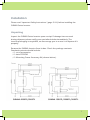
1
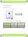
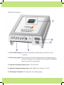
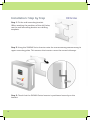
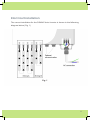
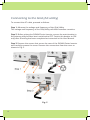
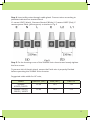
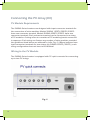
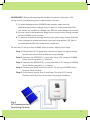
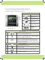
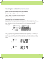
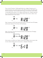
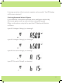
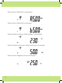
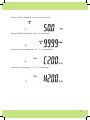
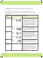
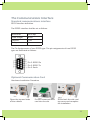
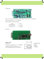
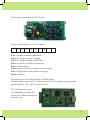
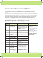
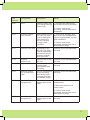
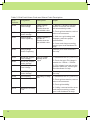
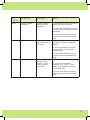
SUNNA SERIES PHOTOVOLTAIC INVERTER USER MANUAL SUNNA 1500TL / 2000TL / 3000TL / 4200TL / 5000TL Contents Introduction...............................................................................................................................2 Important Safety Instructions................................................................................................4 Product Overview....................................................................................................................5 Installation................................................................................................................................10 Front Panel Functional Descriptions................................................................................16 Starting the SUNNA Series Inverter..................................................................................17 The Communications Interface.........................................................................................23 Inverter Status Diagnostics and Repair...........................................................................26 Specifications...........................................................................................................................30 Introduction Thank you for buying this SUNNA Series Inverter. Many years of design experience has gone into the construction of this device, and your SUNNA Series Inverter should give your solar power system many years of trouble-free operation. Your new Inverter is a complex electronic system, and over its life-time it will be confronted with a variety of local conditions. If a malfunction of your SUNNA Series Inverter occurs, please contact your specialised dealer directly. Your dealer will assist you or will refer you to someone who can help with your query. Please read this User Manual carefully to familiarise yourself with your new device. Please pay particular attention to information regarding the installation and commissioning of your SUNNA Series Inverter. 2 Important Safety Instructions General ! Warning! Incorrect operation and/or work performed can cause serious injury and damage! Only qualified personnel are authorised to install your SUNNA Series Inverter; installation should be carried out within the scope of the respective technical regulations. Do not start operation or carry out maintenance work before reading the chapter ‘Important Safety Instructions’. This manual contains important instructions for the SUNNA Series1500TL, 2000TL, 3000TL, 4200TL, 5000TL that should be followed during installation and maintenance of the inverters. ! Housing Warning! These servicing instructions are for use by qualified personnel only. To reduce the risk of electric shock, do not perform any servicing other than that specified in the operating instructions unless qualified to do so. Only qualified installers are authorised to open the connection area. Do not open the connection area when the inverter is under load (ie. ensure power is not running through inverter). Only trained service staff may open the upper portion (power stage) of the SUNNA Series Inverter, and only when the inverter is not under load. Repair Only trained service staff are authorised to carry out repairs to the SUNNA Series Inverter unit. 3 PV Module Before connecting the solar modules, you must check whether the voltage parameters specified in the manufacturer’s data correspond with the actual parameters. When checking the voltage reading, please take into account that solar modules supply a higher no-load voltage when temperature is low and sunlight level remains unchanged. At 14°F (-10°C) the open-circuit voltage of the PV modules must never exceed 500V. The data sheet of the solar module will tell you the temperature factors applicable for determining the theoretical open-circuit voltage at 14°F (-10°C). If the solar modules exceed an opencircuit voltage of 500V, the SUNNA Series Inverter may be damaged. In these circumstances all warranty rights will be void. The SUNNA Series Inverter includes a Residual Current Monitoring Unit (RCMU) according to VDE0126-1-1. This device measures the Earth current of the PV array and will prevent the inverter from feeding the grid in the case of an Earth fault. Grid Connection Only appropriately licensed contractors are authorised to connect the SUNNA Series Inverter to the grid. Consult your local authorities for specific requirements. Before connecting the SUNNA Series Inverter to the grid, permission for the connection must be granted by the utility company. 4 Product Overview External Dimensions Module number Dimensions (mm) L H D SUNNA 1500TL, 2000TL, 3000TL 455 430 170 SUNNA 4200TL, 5000TL 455 510 170 5 Unit Description 1. LCD & LED Display: Shows the operation information and status of the inverter. 2. Solar Array Input: Plug-and-play connector terminals for the connection of the solar modules (The SUNNA 1500TL/2000TL/SR3000TL only have one PV string input). 3. Standard Communication Port : EPO & RS232. 4. Optional Communication Slot: USB, RS485, Dry Contact, TCP/ IP. 5. AC Output Terminal: AC output for the utility supply. 6 Installation Please read ‘Important Safety Instructions’ (page 3 & 4) before installing the SUNNA Series Inverter. Unpacking Inspect the SUNNA Series Inverter upon receipt. If damage has occurred during shipment please notify your specialised dealer immediately. The inverter packaging is recyclable, we encourage you to re-use it or dispose of it properly. Remove the SUNNA Inverter from its box. Check the package contents. Standard contents should include: ✓ 1 set of accessories ✓ 1 data CD-ROM ✓ 1 Mounting Frame Accessory Kit (shown below): SUNNA 4200TL/5000TL SUNNA 1500TL/2000TL/3000TL 7 Installation Requirements The SUNNA Series Inverter is heavy. Take this weight into consideration when choosing the installation site and method of installation. To ensure proper operation and long operating life, always position the SUNNA Series Inverter according to the following requirements: SUNNA1500TL/2000TL/3000TL 23Kg SUNNA 4200TL/5000TL 28Kg (1) The SUNNA Series Inverter is designed for outdoor installation, and should be installed away from direct sunlight. Increased ambient temperatures and/or installation in poorly ventilated and warm indoor locations mayreduce the yield of the PV system. The optimum ambient temperature lies within the -25°C to +50°C range. (2) The SUNNA Series Inverter is designed to be mounted on a vertical wall. If installing the unit outdoors, make sure that it is not slanting forward. We advise against installing the unit in a horizontal position. 8 (3) When choosing the installation site, ensure there is enough space for heat dissipation. Under normal conditions, installers should adhere to the following guidelines regarding space to be left clear around the inverter: Mounting the Unit We recommend that you use the supplied wall mounting bracket to mount the SUNNA Series Inverter. For vertical installation and installation on solid concrete or block walls, be sure to take into account the weight of the inverter when selecting the mounting materials. If you do not want to use the supplied wall mounting bracket, refer to the dimensions shown in the drawing above. The procedure for mounting the inverter using the wall mounting bracket is described on the following pages. 9 Installation: Step by Step Step 1. Fit the wall mounting bracket. When marking the positions of the drill holes, use the wall mounting bracket as a drilling template. Step 2. Hang the SUNNA Series Inverter onto the wall mounting bracket using its upper mounting plate. This ensures the inverter cannot be moved sideways. Step 3. Check that the SUNNA Series Inverter is positioned securely on the bracket. 10 Electrical Installation The correct installation for the SUNNA Series Inverter is shown in the following diagram below (Fig. 1) Fig. 1 11 Connecting to the Grid (AC utility) To connect the AC cable, proceed as follows: Step 1. Measure the voltage and frequency of the Grid/Utility. The voltage and frequency of the Grid/Utility will differ between countries. Step 2. Before wiring the SUNNA Series Inverter, ensure the main breaker in the primary utility breaker box is switched to OFF. Switch this breaker to ON only after all wiring has been completed as instructed in this User Manual. Step 3. Remove the screws that secure the case of the SUNNA Series Inverter and carefully remove the cover. Remove the connection from the cover as shown in Fig. 2. Fig. 2 12 Step 4. Insert utility wires through cable gland. Connect wires according to polarities indicated on terminal block. L1 means LINE1 (black), N means Neutral (White), L2 means LINE2 (Red), E means system Earth (yellow-green) as shown in Fig. 3 Fig. 3 Step 5. Fix the housing cover of the SUNNA Series Inverter and evenly tighten the four screws. To prevent risk of electric shock, ensure the Earth wire is properly Earthed before operating the SUNNA Series Inverter. Suggested cable width for AC wire; Model SUNNA 4200TL/5000TL SUNNA 1500TL/ 2000TL/ 3000TL Diameter (mm) >2.59 Area (mm2) >5.5 AWG no. >10 >2.05 >3.5 >12 13 Connecting the PV Array (DC) PV Module Requirements The SUNNA Series Inverters are designed with input connector terminals for the connection of solar modules. Models SUNNA 1500TL/2000TL/3000TL have one connector terminal, Models SUNNA 4200TL/5000TL have two connector terminals. Each connector terminal can be connected to a string of PV modules. A string refers to a number of PV modules/panels connected in sequence. Each string can feature any number of solar modules, provided the guidelines listed below are adhered to (refer Fig. 4). Where inverters have input connector terminals for two strings (eg SUNNA 4200TL/5000TL), each string configuration does not have to be identical. Wiring to the PV Module The SUNNA Series Inverter is equipped with PV quick connects for connecting up to two PV strings. Fig. 4 14 GUIDELINES: When determining the number of panels required in a PV string, ensure the following three requirements are met: 1. To avoid damage to the SUNNA Series Inverter, make sure the maximum open circuit voltage (Voc) of each PV string is less than 500 Vdc under any condition. Voltage over 500 Vdc will damage the inverter. 2. Do not exceed the maximum array short circuit/current rating marked on the SUNNA Series Inverter. 3. To achieve maximum energy harvest from your array, ensure that the Vmp (voltage at maximum power) does not drop below 150 Vdc or increase above 450 Vdc under most conditions. To wire the PV array to the SUNNA Series Inverter, follow these steps: Step 1: Check that the PV generator connectors have the right polarity and do not exceed the maximum string voltage. Step 2: Connect the POSITIVE (+) wire from the #1 PV string to SUNNA Series Inverter positive (+) connect. Step 3: Connect the NEGATIVE (–) wire from the #1 PV string to SUNNA Series Inverter negative (–) connect. Step 4: Connect the Earth wire from the #1 PV string to SUNNA Series Inverter Earth connect. Step 5: If necessary, repeat Step 2 and Step 4 for the #2 PV string. Double check that the wires are in the proper locations. Fig. 5 DC Connections for a Two-String PV Array 15 Front Panel Functional Descriptions Symbols on the LCD Display Panel LCD Display Symbol Description Utility Source Inverter working in specified mode Solar Cell Inverter operation mode Flow Chart 4 Digits Measurement Display LED Indicators 2 RED LED steadily lights up to indicate an Earth fault or a DC input isolation fault. 3 YELLOW LED steadily lights up to indicate that the utility (ex. voltage, frequency etc.) does not match the input standard of the inverter. 4 Green LED steadily lights up to indicate that the Solar Cell power is greater than sleep power; the LED flashes to indicate that the Solar Cell power is smaller than sleep power. Control Keypads 16 5 Special Function Log in /out. 6 Go to next page. 7 To re-confirm the change of Inverter Setting. 8 Go to previous page. Starting the SUNNA Series Inverter Before the inverter is started, check the following: The housing cover is securely screwed tight. The AC breaker is OFF. The DC cables (PV strings) are fully connected. The AC (utility) cable is connected correctly. Operation Test and Installation Instruction Connect the PV string voltage by switching on the DC circuit breaker. The SUNNA Series Inverter starts automatically when it receives DC voltage greater than 120Vdc. All of the LEDs will light up. The LCD display will illustrate drawing A. A. After 3 seconds, the LCD display will illustrate from drawing A to drawing B1 and B2. The Green LED flashes to indicate that the DC input power is smaller than sleep power. The yellow LED steadily lights up to indicate that no utility exists. B1. B2. 17 Turn on the AC breaker. If Utility specification (ex. voltage, frequency etc.) is matched with the specs of the inverter, after 300 seconds the LCD display will illustrate drawing C. And the Yellow LED will go out to indicate that the utility is acceptable by the inverter. If the Utility’s specification (ex. voltage, frequency etc.) is not matched with the specs of the inverter then an error code or error status will be shown on the screen. C. After 5 seconds, if the DC soft start of the inverter is successful, the LCD display will illustrate drawing D. The Green LED still flashes. D. After 10 seconds, if the AC soft start of inverter is successful the LCD display will illustrate drawing E. E. If the inverter is in failure (ex. Output Current Over Range), then an error code or error status will be shown on the screen. ( Example: Drawing F) F. 18 If start-up operation of the inverter is complete and successful. The LCD display will illustrate drawing E. Checking Measured Values & Figures If you would like to check the measured values and figures detected by the Inverter, please scroll up and scroll down using the key pad. When scrolling down using the key pad, the LCD display will illustrate as follows: Input DC Voltage of String A, as drawing G. G. Input DC Voltage of String B, as drawing H. H. Input DC Current of String A, as drawing I. I. Input DC Current of String B, as drawing J. J. 19 Output Power of Booster A, as drawing K. K. Output Power of Booster B, as drawing L. L. Output Voltage of Inverter (Utility Voltage), as drawing M. M. Output Frequency of Inverter (Utility Frequency), as drawing N. N. Output Current Supplied to Load, as drawing O. O. 20 Output Power Supplied to Load, as drawing P. P. Energy KWH Supplied to Load, as drawing Q. Q. Inverter Inner Temperature (°C, °F) , as drawing R. R. Heat Sink Temperature (°C, °F) , as drawing S. S. 21 SUNNA Series Inverter Status Descriptions The SUNNA Series Inverter starts up automatically when DC-power from the PV panel is sufficient. Once the inverter starts, it enters into one of the following status: Operation mode 22 LCD panel display Description Normal In this mode, the SUNNA Series Inverter works normally. Whenever the supplied power from PV panel is sufficient (500VDC>PV>120VDC), the SUNNA Series Inverter converts power to the grid as generated by the PV panel. In normal mode, the green LED is on to indicate that power is being fed to the grid. Standby If the power is insufficient, (60VDC<PV<120VDC) the SUNNA Series Inverter enters into a standby mode but will attempt to connect to the grid. Error The internal intelligent controller can continuously monitor and adjust the system status. If the SUNNA Series Inverter finds any unexpected conditions such as grid problems or internal failure, it will display the information on its LCD and light up the red LED. EPO Emergency Power Off Mode. In this mode, the SUNNA Series Inverter does not take any power from the grid. Shutdown In case of little or no sunlight, the SUNNA Series Inverter automatically stops running. In this mode, the SUNNA Series Inverter does not take any power from the grid. The display and all of the LEDs on the front panel do not work. The Communications Interface Standard communications interface RS232 interface definition The RS232 interface shall be set as follows: Baud Rate Data Length Stop Bit Parity 9600 bps 8 bits 1 bit None The Pin Assignments of true RS232 type. The pin assignments of true RS232 type are illustrated as follows: Pin 2: RS232 Rx Pin 3: RS232 Tx Pin 5: Earth Optional Communication Card Hardware Installation Procedure Open the top and sides of the cabinet Put the communication card into the slot Screw back the side and top cover and complete the installation 23 RS-485 card CN1 is for the function of the terminal resistor. Short Pin 1-2 to enable the function and short Pin 2-3 to disable it. CN2 is RS485 terminal definition CN2 1 → Earth 2 → A/Data+ 3 → B/Data- USB card CN2 for USB. Definition Comply with USB version 1.0 & 1.5Mbps. Comply with USB HID Version 1.0. The Pin Assignments of the USB card: 24 True Relay Contact Board (DCE-B card) The pin assignments of 10-Pin Terminal: 1 2 3 4 5 6 7 8 Pin 1: Voltage of utility is abnormal. Pin 2: PV strings voltage is normal. Pin 3: PV strings voltage is abnormal. Pin 4: Frequency of utility is abnormal. Pin 5: Anti-islanding. Pin 6: Output current of inverter exceeds range. Pin 7: Temperature of heat-sink is too high. Pin 8: Common. The capacity of each relay contact is 40Vdc/25mA. Flexible signal output for N.C. (Normal close) or N.O. (Normal open) contact by shorting Pin 1-2 or Pin 2-3 from of JP1-5. TCP/ IP (Ethernet) cards For installation, please refer to the User’s Manual attached with the card. 25 Inverter Status Diagnostics and Repair The SUNNA Series Inverter is equipped with an on-board self diagnostic system. This system can automatically identify a large number of possible operational issues and provide notification via its LCD screen. This system makes it possible to quickly isolate technical issues, and to distinguish between Service Codes related to the installation versus Service Codes which are internal to the inverter. Whenever the self diagnostic system has identified a particular issue, the respective Service Code is displayed on the LCD screen. Table 2. Inverter Error Code and Error Code Description 26 LCD Indicate Designation Description Repair Er00 DC_BUS pre-Charge fail The Inverter is in soft start procedure, but the DC Bus cannot reach and maintain anticipative charging voltage. 1. Disconnect ALL PV (+) or PV (-). Er03 INVERTER voltage abnormal The Inverter Output voltage is abnormal. Er07 DC_BUS over-voltage The DC BUS inside is lower or high than expected. Er08 DC_BUS under-voltage Er17 EEPROM ERROR on the control board EEPROM Data is wrong. Er19 DC_BUS discharge fail Capacitors of the DC Bus can’t be discharged down. Er22 Output Relay fail The Inverter Output Relay is abnormal. Er24 Output Current sense fail The Inverter Output Current fails to detect. Er25 BOOSTER_A over-current Er26 BOOSTER_B over-current Over-current on the DC side. This fault code is displayed if the current in the DC network is larger than specified. Er30 Rating setting of Driver board does not match EEROM of control board EEPROM Data is wrong. 2. Wait for few seconds. 3. After the LCD switches off, reconnect and check again. 4. If error code keeps recurring, contact your local distributor. LCD indicate Designation Description Repair Er06 EPO Inverter enters into EPO mode (Emerge Power Off). 1. Remove the short circuit occurred at the EPO terminal. Over-current on the AC side. This fault code is displayed if the current in the AC network is larger than specified. 1. Turn off AC breaker, and then check the peripheral AC system configuration and the grid conditions. Er09 Inverter Output over-current 2. If error code keeps recurring, contact your local distributor. 2. If error code keeps recurring, contact your local distributor for help. Er11 Inverter over-load Overload on the AC side. This fault code is displayed if the load in the AC network is larger than specified. Contact your local distributor for help. Er13 Inverter short-circuit Short-circuit on the AC side. Contact your local distributor for help. Er14 Inverter PLL fail The phase of Inverter can’t synchronize with the utility. Contact your local distributor for help. Er29 Inverter output DC current over spec. The DC component of the electricity fed into the grid is longer than the permissible range. Contact your local distributor for help. Er10 Inverter Over temperature The internal temperature is too high. 1. Try to reduce the ambient temperature. 2. Move the inverter to a cooler place. 3. If error code keeps recurring, contact your local distributor for help. Er18 Heat Sink Over temperature The Heat Sink temperature is too high. Contact your local distributor for help. 27 Table 3. Grid Fault Alarm Code and Alarm Code Description LCD indicate Designation Description Repair AL00 Utility Voltage Over-Voltage Utility Voltage greater or smaller than the permissible value. 1. Wait for 1 minute, if the grid returns to normal, the inverter will automatically restart. AL01 Utility Voltage Under-Voltage AL02 Utility Voltage Over-Frequency Utility Frequency greater or smaller than the permissible value. 3. Make sure grid voltage and frequency meet the proper specifications. 2. Check grid connection, such as wires and connectors. 4. If error code keeps recurring, contact your local distributor for help. AL03 Utility Voltage Under-Frequency Contact your local distributor for help. AL04 BOOSTER_A Input Over-Voltage AL05 BOOSTER_A Input Under-Voltage AL06 BOOSTER_B Input Over-Voltage 3. If PV voltage is normal and the problem still occurs, contact your local distributor for help. AL07 BOOSTER_B Input Under-Voltage Contact your local distributor for help. AL08 Anti-Islanding AL 13 Phase of Utility is fail Over or Under voltage at DC input. No Utility or Utility Fail. 1. Disconnect ALL PV (+) or PV (-). 2. Check the open PV voltage is outside the 120Vdc ~ 500Vdc. 1. Disconnect ALL PV (+) or PV (-) 2. Check grid connection, such as wires and connectors. 3. Check grid usability. AL14 28 Waveform of Utility is fail 4. If Utility is normal and the error code keeps recurring, contact your local distributor for help. LCD indicate Designation Description Repair AL09 Inverter Voltage unbalance Inverter Voltage Waveform is in unbalance. 1. Shut down inverter (unplug PV generator from the input). 2. Check grid usability and restart inverter (plug PV generator from the input). 3. If error code keeps recurring, contact your local distributor for help. AL10 GFDI Leakage current on 1. Unplug PV generator from Earth conductor is the input, check AC peripheral too high. system. 2. After the problem is cleared, re-plug the PV. Check the PVInverter status. 3. If error code keeps recurring, contact your local distributor for help. AL11 Isolation Fault The impedance is between PV (+) and PV (-) and Earth is smaller than 1MΩ. 1. Disconnect ALL PV (+) or PV (-). 2. Check the impedance between PV (+) & PV (-) and Earth. The impedance must be larger than 2MΩ. 3. If error code keeps recurring, contact your local distributor for help. 29 Specifications Unit Model Inverter Technology SUNNA 1500TL SUNNA 2000TL Conversion Mode SUNNA 3000TL SUNNA 4200TL SUNNA 5000TL Sine-wave, Current source, High frequency PWM Isolation Method Transformer-less Design* DC Input Data Nominal DC Voltage 360 VDC Maximum DC Input Voltage 500 VDC Work Range Maximum DC Input Current (each MPPT follower) 120VDC~500VDC** 10.5 Amp 14.6 Amp MPPT Range 22 Amp 14 Amp 17.6 Amp 150 VDC ~ 450 VDC MPPT Follower 1 2 AC Output Data Nominal AC Power 1500 2000 3000 Nominal AC Voltage Output Connection Method 8.7 Amp 13 Amp 21.7 Amp 47 ~ 50.5 Hz >0.99 with nominal AC current DC Injection Current Distortion 17.4 Amp 207~264 Vac 6.5 Amp Frequency Power Factor 5000 1-Phase / 2-Wires (L, N, E) AC Voltage Range Nominal AC Current 4000 AC 230V < 20mA Total Harmonic current : Less than 5% Single Harmonic current : Less than 3% Efficiency Data Maximum Cont. Efficiency >96% Euro Efficiency >94% Environment Operating Temperature Humidity -20 °C ~ +50 °C 0 to 90% (without condensation) Altitude 0 ~ 2000 M / 0 ~ 6600 ft Mechanical Data Dimensions (H x W x D in mm) Weight (Kgs) 30 455 x 430 x 170 455 x 510 x 170 23 28 Protection Class IP65, Outdoors Cooling Free Convection AC Connection Terminal DC Connection Multi-Contact Unit Model SUNNA 1500TL SUNNA 2000TL SUNNA 3000TL SUNNA 4200TL SUNNA 5000TL Communication Communication Interface Standard RS232 Optional USB, RS485, dry contact, TCP/IP Front Panel LCD Boost input Voltage/Boost input Current/Boost input Power/AC output Voltage /AC output frequency/AC output current /AC output power/AC Energy yield/Inner Temperature/Heat sink Temperature /Status message/ Error message RED LED Yellow Green Key Pad Leakage current fault or DC input isolation fault Spec. of Utility is not matched with the Utility specifications of the inverter Solar Cell power is greater or smaller than sleep power UP key/ Down key/ Function key/ Enter key Protection Utility Islanding operation detection Over Temperature Over/under Voltage, Over/ under Frequency, Earth fault, DC Isolation fault Passive : Voltage phase jump detection Active : Reactive power control Reduced output power Certification Performance and Safety Compliance EMI/EMC North American Australia ER G83/1, VDE0126-1-1, EN50178, IEC62103 EN 61000-6-1, EN 61000-6-2, EN 61000-6-3, EN 61000-6-4 UL1741, IEEE1547 AS3100, AS/NZS4777 * If isolation is necessary, option one extra transformer. ** The rated range should be 150VDC-500VDC in order to get the rated output. 31