1
Sun ZFS Storage 7120, 7320, and 7420
Appliance Installation Guide
Part No: E38245
December 2012 E38245–01
Copyright © 2009, 2011, 2012, Oracle and/or its affiliates. All rights reserved.
This software and related documentation are provided under a license agreement containing restrictions on use and disclosure and are protected by intellectual
property laws. Except as expressly permitted in your license agreement or allowed by law, you may not use, copy, reproduce, translate, broadcast, modify, license,
transmit, distribute, exhibit, perform, publish or display any part, in any form, or by any means. Reverse engineering, disassembly, or decompilation of this software,
unless required by law for interoperability, is prohibited.
The information contained herein is subject to change without notice and is not warranted to be error-free. If you find any errors, please report them to us in writing.
If this is software or related documentation that is delivered to the U.S. Government or anyone licensing it on behalf of the U.S. Government, the following notice is
applicable:
U.S. GOVERNMENT END USERS. Oracle programs, including any operating system, integrated software, any programs installed on the hardware, and/or
documentation, delivered to U.S. Government end users are "commercial computer software" pursuant to the applicable Federal Acquisition Regulation and
agency-specific supplemental regulations. As such, use, duplication, disclosure, modification, and adaptation of the programs, including any operating system,
integrated software, any programs installed on the hardware, and/or documentation, shall be subject to license terms and license restrictions applicable to the
programs. No other rights are granted to the U.S. Government.
This software or hardware is developed for general use in a variety of information management applications. It is not developed or intended for use in any inherently
dangerous applications, including applications that may create a risk of personal injury. If you use this software or hardware in dangerous applications, then you shall
be responsible to take all appropriate fail-safe, backup, redundancy, and other measures to ensure its safe use. Oracle Corporation and its affiliates disclaim any
liability for any damages caused by use of this software or hardware in dangerous applications.
Oracle and Java are registered trademarks of Oracle and/or its affiliates. Other names may be trademarks of their respective owners.
Intel and Intel Xeon are trademarks or registered trademarks of Intel Corporation. All SPARC trademarks are used under license and are trademarks or registered
trademarks of SPARC International, Inc. AMD, Opteron, the AMD logo, and the AMD Opteron logo are trademarks or registered trademarks of Advanced Micro
Devices. UNIX is a registered trademark of The Open Group.
This software or hardware and documentation may provide access to or information on content, products, and services from third parties. Oracle Corporation and
its affiliates are not responsible for and expressly disclaim all warranties of any kind with respect to third-party content, products, and services. Oracle Corporation
and its affiliates will not be responsible for any loss, costs, or damages incurred due to your access to or use of third-party content, products, or services.
Ce logiciel et la documentation qui l’accompagne sont protégés par les lois sur la propriété intellectuelle. Ils sont concédés sous licence et soumis à des restrictions
d’utilisation et de divulgation. Sauf disposition de votre contrat de licence ou de la loi, vous ne pouvez pas copier, reproduire, traduire, diffuser, modifier, breveter,
transmettre, distribuer, exposer, exécuter, publier ou afficher le logiciel, même partiellement, sous quelque forme et par quelque procédé que ce soit. Par ailleurs, il est
interdit de procéder à toute ingénierie inverse du logiciel, de le désassembler ou de le décompiler, excepté à des fins d’interopérabilité avec des logiciels tiers ou tel que
prescrit par la loi.
Les informations fournies dans ce document sont susceptibles de modification sans préavis. Par ailleurs, Oracle Corporation ne garantit pas qu’elles soient exemptes
d’erreurs et vous invite, le cas échéant, à lui en faire part par écrit.
Si ce logiciel, ou la documentation qui l’accompagne, est concédé sous licence au Gouvernement des Etats-Unis, ou à toute entité qui délivre la licence de ce logiciel
ou l’utilise pour le compte du Gouvernement des Etats-Unis, la notice suivante s’applique :
U.S. GOVERNMENT END USERS. Oracle programs, including any operating system, integrated software, any programs installed on the hardware, and/or
documentation, delivered to U.S. Government end users are "commercial computer software" pursuant to the applicable Federal Acquisition Regulation and
agency-specific supplemental regulations. As such, use, duplication, disclosure, modification, and adaptation of the programs, including any operating system,
integrated software, any programs installed on the hardware, and/or documentation, shall be subject to license terms and license restrictions applicable to the
programs. No other rights are granted to the U.S. Government.
Ce logiciel ou matériel a été développé pour un usage général dans le cadre d’applications de gestion des informations. Ce logiciel ou matériel n’est pas conçu ni n’est
destiné à être utilisé dans des applications à risque, notamment dans des applications pouvant causer des dommages corporels. Si vous utilisez ce logiciel ou matériel
dans le cadre d’applications dangereuses, il est de votre responsabilité de prendre toutes les mesures de secours, de sauvegarde, de redondance et autres mesures
nécessaires à son utilisation dans des conditions optimales de sécurité. Oracle Corporation et ses affiliés déclinent toute responsabilité quant aux dommages causés
par l’utilisation de ce logiciel ou matériel pour ce type d’applications.
Oracle et Java sont des marques déposées d’Oracle Corporation et/ou de ses affiliés.Tout autre nom mentionné peut correspondre à des marques appartenant à
d’autres propriétaires qu’Oracle.
Intel Xeon sont des marques ou des marques déposées d'Intel Corporation. Toutes les marques SPARC sont utilisées sous licence et sont des marques ou des marques
déposées de SPARC International, Inc. AMD, Opteron, le logo AMD et le logo AMD Opteron sont des marques ou des marques déposées d'Advanced Micro Devices.
UNIX est une marque déposée d'The Open Group.
Ce logiciel ou matériel et la documentation qui l'accompagne peuvent fournir des informations ou des liens donnant accès à des contenus, des produits et des services
émanant de tiers. Oracle Corporation et ses affiliés déclinent toute responsabilité ou garantie expresse quant aux contenus, produits ou services émanant de tiers. En
aucun cas, Oracle Corporation et ses affiliés ne sauraient être tenus pour responsables des pertes subies, des coûts occasionnés ou des dommages causés par l'accès à
des contenus, produits ou services tiers, ou à leur utilisation.
121219@25097
Contents
Preface .....................................................................................................................................................7
1
Introduction ...........................................................................................................................................9
Overview ..................................................................................................................................................9
Introduction ....................................................................................................................................9
2
Installation ............................................................................................................................................13
Installation ........................................................................................................................................... 13
Introduction ................................................................................................................................. 13
Overview ............................................................................................................................................... 14
Precautions ................................................................................................................................... 14
Prerequisites ................................................................................................................................. 14
Controller, Cabinet and Disk Shelf Installation Tasks ............................................................ 15
7x20 Controllers .................................................................................................................................. 15
7x20 Controller Installation Tasks ............................................................................................. 15
Prerequisites ................................................................................................................................. 15
Tools and Equipment Needed .................................................................................................... 16
Tasks .............................................................................................................................................. 16
DE2 24C ................................................................................................................................................ 29
Precautions ................................................................................................................................... 29
Prerequisites ................................................................................................................................. 30
Tools and Equipment Needed .................................................................................................... 30
Tasks .............................................................................................................................................. 30
DE2 24P ................................................................................................................................................ 37
Precautions ................................................................................................................................... 37
Prerequisites ................................................................................................................................. 37
Tools and Equipment Needed .................................................................................................... 38
3
Contents
Tasks .............................................................................................................................................. 38
Sun Disk Shelf ...................................................................................................................................... 45
Precautions ................................................................................................................................... 45
Prerequisites ................................................................................................................................. 45
Tools and Equipment Needed .................................................................................................... 45
Tasks .............................................................................................................................................. 46
3
Cabling ..................................................................................................................................................51
Cabling .................................................................................................................................................. 51
Cabling Diagrams ........................................................................................................................ 51
7120 Cabling ........................................................................................................................................ 52
Connecting Sun Disk Shelves/J4x00s to the Sun ZFS Storage 7120 ....................................... 52
7320 Cabling ........................................................................................................................................ 54
Connecting Sun Disk Shelves/J4x00s to the Sun ZFS Storage 7320 ....................................... 54
7320 Cluster Cabling ........................................................................................................................... 56
Connecting Sun Disk Shelves/J4x00s to the Sun ZFS Storage 7320 Cluster ......................... 56
7420 Cabling pt.1 ................................................................................................................................. 58
Connecting Sun Disk Shelves/J4x00s to the Sun ZFS Storage 7420 (2 HBAs) ...................... 58
7420 Cabling pt.2 ................................................................................................................................. 60
Connecting Sun Disk Shelves/J4x00s to the Sun ZFS Storage 7420 (3 HBAs) ...................... 60
7420 Cabling pt.3 ................................................................................................................................. 62
Connecting Sun Disk Shelves/J4x00s to the Sun ZFS Storage 7420 (4 HBAs) ...................... 62
7420 Cabling pt.4 ................................................................................................................................. 65
Connecting Sun Disk Shelves/J4x00s to the Sun ZFS Storage 7420 (5 HBAs) ...................... 65
7420 Cabling pt.5 ................................................................................................................................. 68
Connecting Sun Disk Shelves/J4x00s to the Sun ZFS Storage 7420 (6 HBAs) ...................... 68
7420 Cluster Cabling pt.1 ................................................................................................................... 71
Connecting Sun Disk Shelves/J4x00s to the Sun ZFS Storage 7420 Cluster (2 HBAs) ........ 71
7420 Cluster Cabling pt.2 ................................................................................................................... 74
Connecting Sun Disk Shelves/J4x00s to the Sun ZFS Storage 7420 Cluster (3 HBAs) ........ 74
7420 Cluster Cabling pt.3 ................................................................................................................... 77
Connecting Sun Disk Shelves/J4x00s to the Sun ZFS Storage 7420 Cluster (4 HBAs) ........ 77
7420 Cluster Cabling pt.4 ................................................................................................................... 80
Connecting Sun Disk Shelves/J4x00s to the Sun ZFS Storage 7420 Cluster (5 HBAs) ........ 80
7420 Cluster Cabling pt.5 ................................................................................................................... 83
4
Sun ZFS Storage 7120, 7320, and 7420 Appliance Installation Guide • December 2012 E38245–01
Contents
Connecting Sun Disk Shelves/J4x00s to the Sun ZFS Storage 7420 Cluster (6 HBAs) ........ 83
DE2-24 .................................................................................................................................................. 87
Connecting DE2 Enclosures to the Sun ZFS Storage 7120 ..................................................... 87
DE2-24 .................................................................................................................................................. 89
Connecting DE2 Enclosures to the Sun ZFS Storage 7320 ..................................................... 89
DE2-24 .................................................................................................................................................. 91
Connecting DE2 Enclosures to the Sun ZFS Storage 7320 Cluster ........................................ 91
DE2-24x2 .............................................................................................................................................. 93
Connecting DE2 Enclosures to the Sun ZFS Storage 7420 (2 HBAs) .................................... 93
DE2-24x3 .............................................................................................................................................. 95
Connecting DE2 Enclosures to the Sun ZFS Storage 7420 (3 HBAs) .................................... 95
DE2-24x4 .............................................................................................................................................. 97
Connecting DE2 Enclosures to the Sun ZFS Storage 7420 (4 HBAs) .................................... 97
DE2-24x5 ............................................................................................................................................ 100
Connecting DE2 Enclosures to the Sun ZFS Storage 7420 (5 HBAs) .................................. 100
DE2-24x6 ............................................................................................................................................ 103
Connecting DE2 Enclosures to the Sun ZFS Storage 7420 (6 HBAs) .................................. 103
DE2-24x2 ............................................................................................................................................ 106
Connecting DE2 Enclosures to the Sun ZFS Storage 7420 Cluster (2 HBAs) ..................... 106
DE2-24x3 ............................................................................................................................................ 109
Connecting DE2 Enclosures to the Sun ZFS Storage 7420 Cluster (3 HBAs) ..................... 109
DE2-24x4 ............................................................................................................................................ 112
Connecting DE2 Enclosures to the Sun ZFS Storage 7420 Cluster (4 HBAs) ..................... 112
DE2-24x5 ............................................................................................................................................ 115
Connecting DE2 Enclosures to the Sun ZFS Storage 7420 Cluster (5 HBAs) ..................... 115
DE2-24x6 ............................................................................................................................................ 118
Connecting DE2 Enclosures to the Sun ZFS Storage 7420 Cluster (6 HBAs) ..................... 118
HBA Expansion pt.1 .......................................................................................................................... 122
Expanding from 2 to 3 HBAs .................................................................................................... 122
HBA Expansion pt.2 .......................................................................................................................... 126
Expanding from 3 to 4 HBAs .................................................................................................... 126
HBA Expansion pt.3 .......................................................................................................................... 131
Expanding from 4 to 5 HBAs .................................................................................................... 131
HBA Expansion pt.4 .......................................................................................................................... 135
Expanding from 5 to 6 HBAs .................................................................................................... 135
5
Contents
4
Powering On and Configuring the System .................................................................................... 141
Power .................................................................................................................................................. 141
Powering On and Configuring the Appliance ........................................................................ 141
Tasks ............................................................................................................................................ 142
Next Steps .................................................................................................................................... 144
Initial ................................................................................................................................................... 144
Initial Configuration .................................................................................................................. 144
Prerequisites ............................................................................................................................... 145
Summary ..................................................................................................................................... 145
BUI ............................................................................................................................................... 146
CLI ............................................................................................................................................... 146
Update ................................................................................................................................................ 151
Post-Installation Controller Update ........................................................................................ 151
Glossary .............................................................................................................................................. 153
6
Sun ZFS Storage 7120, 7320, and 7420 Appliance Installation Guide • December 2012 E38245–01
Preface
The Sun ZFS Storage 7x20 Appliance Installation Guide contains installation, cabling and initial
configuration documentation for Oracle's Sun ZFS Storage 7120, 7320, 7420 appliances.
This documentation is also available while using the appliance Browser User Interface (BUI),
accessible via the Help button. The appliance documentation may be updated using the System
Upgrade procedure documented in the System Service Manual.
Who Should Use This Book
This guide is for users and system administrators who install and use the Sun ZFS Storage 7x20
NAS appliances.
Related Documentation
Refer to the following documentation for administration information, hardware overviews,
service procedures and software update notes.
■
Administration Guide, Analytics Guide and Service Manual (http://www.oracle.com/
technetwork/documentation/)
Access to Oracle Support
Oracle customers have access to electronic support through My Oracle Support. For
information, visit http://www.oracle.com/pls/topic/lookup?ctx=acc&id=info or visit
http://www.oracle.com/pls/topic/lookup?ctx=acc&id=trs if you are hearing impaired.
7
8
1
C H A P T E R
1
Introduction
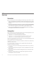
Overview
Introduction
The Sun ZFS Storage 7000 family of products provide efficient file and block data services to
clients over a network, and a rich set of data services that can be applied to the data stored on the
system.
Controllers
■
■
■
7120
7320
7420
Legacy platforms: 7110 | 7210 | 7310 | 7410
Expansion Storage
■
Disk Shelves
Legacy platforms: J4400/J4500
9
Overview
Protocols
Sun ZFS Storage appliances include support for a variety of industry-standard client protocols,
including:
■
■
■
■
■
■
■
■
■
■
SMB
NFS
HTTP and HTTPS
WebDAV
iSCSI
FC
SRP
iSER
FTP
SFTP
Key Features
Sun ZFS Storage systems also include new technologies to deliver the best storage
price/performance and unprecedented observability of your workloads in production,
including:
■
Analytics, a system for dynamically observing the behavior of your system in real-time and
viewing data graphically
■
The ZFS Hybrid Storage Pool, composed of optional Flash-memory devices for acceleration
of reads and writes, low-power, high-capacity disks, and DRAM memory, all managed
transparently as a single data hierarchy
Data Services
To manage the data that you export using these protocols, you can configure your Sun ZFS
Storage system using the built-in collection of advanced data services, including:
LICENSE NOTICE: Remote Replication and Cloning may be evaluated free of charge,
but each feature requires that an independent license be purchased separately for use in
production. After the evaluation period, these features must either be licensed or
deactivated. Oracle reserves the right to audit for licensing compliance at any time. For
details, refer to the "Oracle Software License Agreement ("SLA") and Entitlement for
Hardware Systems with Integrated Software Options."
■
■
■
■
■
■
10
RAID-Z (RAID-5 and RAID-6), mirrored, and striped disk configurations
Unlimited read-only and read-write snapshots, with snapshot schedules
Data deduplication
Built-in data compression
Remote replication of data for disaster recovery
Active-active clustering for high availability (7310, 7320, 7410, and 7420)
Sun ZFS Storage 7120, 7320, and 7420 Appliance Installation Guide • December 2012 E38245–01
Overview
■
■
■
Thin provisioning of iSCSI LUNs
Virus scanning and quarantine
NDMP backup and restore
Availability
To maximize the availability of your data in production, Sun ZFS Storage appliances include a
complete end-to-end architecture for data integrity, including redundancies at every level of the
stack. Key features include:
■
Predictive self-healing and diagnosis of all system hardware failures: CPUs, DRAM, I/O
cards, disks, fans, power supplies
■
ZFS end-to-end data checksums of all data and metadata, protecting data throughout the
stack
■
RAID-6 (double- and triple-parity) and optional RAID-6 across disk shelves
■
Active-active clustering for high availability (7310, 7320, 7410, and 7420)
■
Link aggregations and IP multipathing for network failure protection
■
I/O Multipathing between the controller and disk shelves
■
Integrated software restart of all system software services
■
Phone-Home of telemetry for all software and hardware issues
■
Lights-out Management of each system for remote power control and console access
Browser User Interface (BUI)
The browser user interface
The BUI is the graphical tool for administration of the appliance. The BUI provides an intuitive
environment for administration tasks, visualizing concepts, and analyzing performance data.
Chapter 1 • Introduction
11
Overview
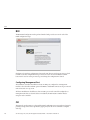
The management software is designed to be fully featured and functional on a variety of web
browsers.
Direct your browser to the system using either the IP address or host name you assigned to the
NET-0 port during initial configuration as follows: https://ipaddress:215 or
https://hostname:215. The login screen appears.
The online help linked in the top right of the BUI is context-sensitive. For every top-level and
second-level screen in the BUI, the associated help page appears when you click the Help
button.
Command Line Interface (CLI)
The CLI is designed to mirror the capabilities of the BUI, while also providing a powerful
scripting environment for performing repetitive tasks. The following sections describe details of
the CLI. When navigating through the CLI, there are two principles to be aware of:
■
Tab completion is used extensively: if you are not sure what to type in any given context,
pressing the Tab key will provide you with possible options. Throughout the
documentation, pressing Tab is presented as the word "tab" in bold italics.
■
Help is always available: the help command provides context-specific help. Help on a
particular topic is available by specifying the topic as an argument to help, for example help
commands. Available topics are displayed by tab-completing the help command, or by typing
help topics.
You can combine these two principles, as follows:
dory:> help tab
builtins
commands
12
general
help
properties script
Sun ZFS Storage 7120, 7320, and 7420 Appliance Installation Guide • December 2012 E38245–01
2
C H A P T E R
2
Installation
Installation
Introduction
This section addresses how to physically install the system chassis into a rack, connect
controllers in a high-availability cluster, and expand storage. The following topics are
described.
■
■
■
■
■
■
■
■
■
■
Overview
Controllers
7x20 family
Expansion Storage
Oracle Storage Drive Enclosure DE2-24C
Oracle Storage Drive Enclosure DE2-24P
Sun Disk Shelf
Cabling
Powering on
Initial configuration
13
Overview
Overview
Precautions
Observe the following cautions when installing any Sun ZFS Storage 7x20 controller or cabinet.
■
Always load equipment into a rack from the bottom up so that it will not become top-heavy
and tip over. Deploy the anti-tip bar to the prevent the rack from tipping during equipment
installation.
■
Ensure that the temperature in the rack does not exceed the controller's maximum ambient
rated temperatures. Consider the total airflow requirements of all equipment installed in the
rack to ensure that the equipment is operated within its specified temperature range.
■
For best results, only qualified Oracle service personnel should perform cluster installation
and configuration. Contact Oracle Service for assistance.
Prerequisites
Refer to the Quick Setup poster that shipped with the product or the following hardware service
sections for an overview of your system controller or cabinet.
■
7120 Overview - view component diagrams and specifications
■
7320 Overview - view component diagrams and specifications, and cluster options
■
7420 Overview - view component diagrams, specifications, and cluster options
If you intend to install disk shelves into the same rack, refer to the Disk Shelf Installation section
for how to install them into the bottom of your rack.
Legacy platform overviews are provided in the 7110 Overview, 7210 Overview, 7310 Overview,
7410 Overview online sections.
For controller installation, check that your rack is compatible with the slide rail and cable
management assembly options as follows:
14
■
The structure is a four-post rack with mounting at both front and back. Two-post racks are
not compatible.
■
The horizontal opening and unit vertical pitch conforms to ANSI/EIA 310-D-1992 or IEC
60927 standards.
■
The distance between the front and back mounting planes is between 24 in and 36 in (610
mm to 915 mm).
■
The distance to the front cabinet door, providing clearance depth in front of the front
mounting plane, is at least 1 in (25.4 mm).
Sun ZFS Storage 7120, 7320, and 7420 Appliance Installation Guide • December 2012 E38245–01
7x20 Controllers
■
The distance to the back cabinet door, providing clearance depth behind the front mounting
plane, is at least 31.5 in (800 mm) with the cable management assembly, or 27.5 in (700 mm)
without the cable management assembly.
■
The distance between structural supports and cable troughs, providing clearance width
between the front and back mounting planes, is at least 18 in (456 mm).
For cabinet installation, you will need a total distance of at least 15 ft/4.5 m for safe maneuvering
when you roll the cabinet off the shipping pallet.
Controller, Cabinet and Disk Shelf Installation Tasks
The following sections provide installation tasks with enumerated steps.
■
■
■
7x20 controller installation tasks
Disk shelf installation tasks
7x10 controller installation tasks (see online section)
7x20 Controllers
7x20 Controller Installation Tasks
This section provides enumerated steps for installing the Sun ZFS Storage 7120, 7320 or 7420
controllers into a rack using the rail assembly in the rack mount kit. Note that if your rack
mount kit shipped with installation instructions, use those instructions instead.
Observe the following cautions:
■
Always load equipment into a rack from the bottom up so that it will not become top-heavy
and tip over. Deploy the anti-tip bar to the prevent the rack from tipping during equipment
installation.
■
Ensure that the temperature in the rack will not exceed the controller's maximum ambient
rated temperatures. Consider the total airflow requirements of all equipment installed in the
rack to ensure that the equipment is operated within its specified temperature range.
Prerequisites
Refer to the Quick Setup poster that shipped with the product or the following sections for an
overview of your controller.
■
■
7120 Overview - view component diagrams and specifications
7320 Overview - view component diagrams and specifications
Chapter 2 • Installation
15
7x20 Controllers
■
7420 Overview - view component diagrams and specifications
Tools and Equipment Needed
To install the system, you need the following tools:
■
■
■
No. 2 Phillips screwdriver
ESD mat and grounding strap
Pencil, stylus, or other pointed device, for pushing front panel buttons
You also need a system console device, such as one of the following:
■
■
■
■
Sun workstation
ASCII terminal
Terminal server
Patch panel connected to a terminal server
Tasks
7x20 Controllers Tasks
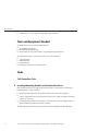
▼ Installing Mounting Brackets on the Controller Chassis
If the mounting brackets are shipped inside the slide rails, you must remove them before
beginning this procedure, as follows.
■
Unpack the slide rails and locate the slide rail lock at the front of the assembly.
■
Squeeze and hold the tabs at top and bottom of the lock (1) while you pull the mounting
bracket out to the stop.
■
Push the mounting bracket release button toward the front of the mounting bracket (2)
while withdrawing the bracket from the assembly.
The following graphic illustrates the procedure for disassembling the 7120/7320 rail kit.
16
Sun ZFS Storage 7120, 7320, and 7420 Appliance Installation Guide • December 2012 E38245–01
7x20 Controllers
The following graphic illustrates the procedure for disassembling the 7420 rail kit.
Chapter 2 • Installation
17
7x20 Controllers
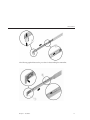
1
Position a mounting bracket against the chassis so that the slide rail lock is at the front of the
chassis, and the keyed openings on the mounting bracket are aligned with the locating pins on
the side of the chassis.
The following graphic illustrates how to attach the 7120/7320 mounting brackets.
18
Sun ZFS Storage 7120, 7320, and 7420 Appliance Installation Guide • December 2012 E38245–01
7x20 Controllers
The following graphic illustrates how to attach the 7420 mounting brackets.
2
With the heads of the four chassis locating pins protruding though the four keyed openings in
the mounting bracket, pull the mounting-bracket toward the front of the chassis until the
mounting-bracket clip locks into place with an audible click.
3
Verify that all mounting pins are securely fastened to the chassis.
4
Repeat to install the remaining mounting bracket on the other side of the chassis.
▼ Installing the Controller Chassis into the Rack Slide Rails
This procedure requires a minimum of two people because of the weight of the chassis.
Attempting this procedure alone could result in equipment damage or personal injury. Always
load equipment into rack from the bottom up.
Chapter 2 • Installation
19
7x20 Controllers
20
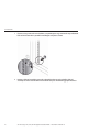
1
If you are using a universal 19-inch cabinet, snap an M6 square cage nut into the top and bottom
holes of the location where you will be installing the rail plate as shown.
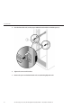
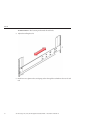
2
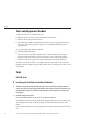
Position a slide rail assembly in your rack so that the brackets at each end of the slide rail
assembly are on the outside of the front and back rack posts. The following graphic illustrates
Sun ZFS Storage 7120, 7320, and 7420 Appliance Installation Guide • December 2012 E38245–01
7x20 Controllers
the rail assembly brackets.
3
Attach each slide rail assembly to the rack posts, but do not tighten the screws completely.
Chapter 2 • Installation
21
7x20 Controllers
22
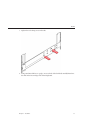
4
From the front of the rack, set the proper width of the rails with the rail-width spacer (1).
5
Tighten the screws on the brackets.
6
Remove the spacer and confirm that the rails are attached tightly to the rack.
Sun ZFS Storage 7120, 7320, and 7420 Appliance Installation Guide • December 2012 E38245–01
7x20 Controllers
7
If your rack includes an anti-tip foot, extend it from the bottom of the rack.
8
Lower the rack stabilization feet if you have not already done so.
9
Push the slide rails into the slide rail assemblies in the rack as far as possible.
Chapter 2 • Installation
23
7x20 Controllers
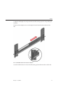
10
Raise the chassis so that the back ends of the mounting brackets are aligned with the slide rail
and insert the chassis into the slide rails, pushing the chassis slowly, until the mounting brackets
meet the slide rail stops (~12 in or 30 cm). You will hear an audible click.
The following graphic illustrates the 7120/7320 chassis insertion and slide rail locks usage.
24
Sun ZFS Storage 7120, 7320, and 7420 Appliance Installation Guide • December 2012 E38245–01
7x20 Controllers
The following graphic illustrates 7420 chassis insertion.
▼ Installing the Cable Management Assembly
This procedure is completed from the back of the equipment rack.
Chapter 2 • Installation
25
7x20 Controllers
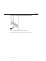
1
Attach the cable management assembly (CMA) rail extension to the left slide rail until the
extension locks into place.
2
Insert the CMA mounting bracket connector into the right slide rail until the connector locks
into place.
26
Sun ZFS Storage 7120, 7320, and 7420 Appliance Installation Guide • December 2012 E38245–01
7x20 Controllers
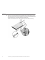
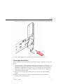
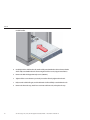
3
Insert the right CMA slide rail connector (1) into the right slide rail assembly (2) until the
connector locks into place.
Chapter 2 • Installation
27
7x20 Controllers
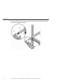
4
28
Insert the left CMA slide rail connector (1) into the rail extension on the left slide rail assembly
(2) until the connector locks into place.
Sun ZFS Storage 7120, 7320, and 7420 Appliance Installation Guide • December 2012 E38245–01
DE2 24C
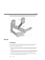
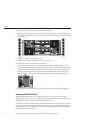
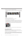
5
After you install and route the cables through the assembly, attach the hook and loop straps (1)
to secure the cables. Then attach the right and left outer latches to support the assembly.
DE2 24C
Precautions
Observe the following cautions when installing the Oracle Storage Drive Enclosure DE2-24C
into a rack using the supplied rail kit. Note that if your rail kit shipped with installation
instructions, use those instructions instead.
■
Always load equipment into a rack from the bottom up so that it will not become top-heavy
and tip over. Deploy the anti-tip bar to prevent the rack from tipping during equipment
installation.
■
Ensure that the temperature in the rack does not exceed the controller's maximum ambient
rated temperatures. Consider the total airflow requirements of all equipment installed in the
rack to ensure that the equipment is operated within its specified temperature range.
■
Do not remove a component if you do not have an immediate replacement. The disk shelf
must not be operated without all components in place.
Chapter 2 • Installation
29
DE2 24C
■
Do not lift the disk shelf by the handles on the power supply with fan modules; they are not
designed to take the weight.
Prerequisites
Refer to the following section for an overview of your disk shelf.
■
Disk Shelf Overview - view component diagrams and specifications
Tools and Equipment Needed
To install the shelf, you need the following tools:
■
Phillips head No. 2 screwdriver that is a minimum of 4 inches long.
■
A mechanical lift is highly recommended because the chassis can weigh approximately 110
lbs (50 kg). At least three people are required: two to install the shelf and one spotter to
engage the rails.
■
If a mechanical lift is not available, remove the power supply with fan modules to reduce the
weight, see Disk Shelf Maintenance Procedures for instructions.
Use one of the following racks for the disk shelf:
■
Sun Rack II 1042/1242 cabinet
■
Any 19-inch wide, 4-post, EIA-compatible rack or cabinet with a front-to-back depth
between vertical cabinet rails of 61 cm to 91 cm (24 in. to 36 in.). The cabinet can have
threaded or unthreaded cabinet rails. Threaded cabinets must be M6 or 10-32 cabinets.
Cabinets must be able to support the weight of all equipment contained within them.
Position the rack where the shelf is to be installed adjacent to the rack where the controller is
installed, if separate. Stabilize the cabinet and lock the casters. To facilitate access, remove doors
from cabinets.
Tasks
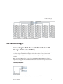
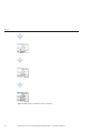
Installing the Disk Shelf into the Rack Slide Rails
1. The Oracle Storage Drive Enclosure DE2-24C requires four standard mounting units (4RU)
of vertical space in the cabinet. Starting at the bottom of the cabinet, locate the appropriate
rack unit (RU) height. Install disk shelves below controllers to prevent the rack from
tipping.
30
Sun ZFS Storage 7120, 7320, and 7420 Appliance Installation Guide • December 2012 E38245–01
DE2 24C
2. If using an unthreaded universal 19-inch or Sun Rack II cabinet, snap one supplied cage nut
into the 8th rack hole, counting upward, in each front rail of the 4RU space.
3. Prepare the screws in each rail end:
Square-hole unthreaded cabinet: No preparation.
Round-hole unthreaded cabinet: Remove the screws from each rail end and discard.
Locate the 8 screws with washers for round-hole cabinets and place aside.
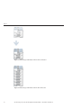
Threaded cabinet: Remove screws and replace them in the opposite direction (from the
inside of the rail flange) so they act as location pins.
4. Position the front of the rails inside the cabinet, with the rail flange inside of the cabinet
flange, and the rail label facing the inside of the cabinet.
Square-hole unthreaded cabinet: The screw heads fit inside the rack holes.
Round-hole unthreaded cabinet: Install two screws with flat and spring washers through
the rack and into the front of each rail. Do not install into the cage nut in the rack, or the clip
nut on the rail.
Chapter 2 • Installation
31
DE2 24C
Threaded cabinet: The location pins fit inside the rack holes.
5. Adjust the rail lengths to fit.
6. Install one screw, plain washer, and spring washer through the rack and into the rear of each
rail.
32
Sun ZFS Storage 7120, 7320, and 7420 Appliance Installation Guide • December 2012 E38245–01
DE2 24C
7. Tighten the two locking screws in the rails.
8. Using a mechanical lift or two people, one at each side of the disk shelf, carefully lift and rest
the shelf on the bottom ledge of the left and right rails.
Chapter 2 • Installation
33
DE2 24C
9. Do not lift using the power supply handles.
10. Carefully slide the shelf into the cabinet. Ensure that the shelf is fully seated within the rails.
If removing the shelf to reseat it, support it at all times.
11. Remove the front side caps, install two screws, two plain washers, and two spring washers
into each front side, and replace the caps.
34
Sun ZFS Storage 7120, 7320, and 7420 Appliance Installation Guide • December 2012 E38245–01
DE2 24C
12. Install one long patchlock screw per rail to secure the rear of the shelf to the rear of the rack.
13. Connect and supply power to the disk shelf as described in the next section.
Powering On the Disk Shelf
Ensure you have met the following electrical safety measures before applying power to the disk
shelf:
■
Provide a suitable power source with electrical overload protection to meet the power
supply input voltage range of 100-240 VAC, 50-60 Hz. The disk shelves are compatible with
100-120 VAC or 200-240 VAC sources. The power source must not be overloaded by the
total number of disk shelves in the cabinet. At full load, each DE2-24 draws 1,140W, and
each Sun Disk Shelf draws 912W.
■
The power source must provide a reliable earth connection for each disk shelf and the
cabinet.
■
Ensure that the power source is easily accessible because the power cord is the main
disconnect device for the disk shelf.
Chapter 2 • Installation
35
DE2 24C
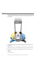
1. Plug a power cord into each power supply with fan module.
2. Plug the other end of the power cords into the external power source for the cabinet.Note:
To guarantee redundancy, power cords must be connected to two separate and independent
power sources.
3. Supply power to the external power source.
4. Place the power supply on/off switches to the "I" on position.
5. Turn on the cabinet circuit breakers, if applicable.
6. After the disk shelf powers on, which could take several minutes, ensure that the system
power indicator on the front of the disk shelf is lit a steady green, and that each power supply
with fan module status indicator on the rear is lit a steady green. If not, power off the disk
shelf as described in the next section and reseat the faulted module. If the module status
indicator is not a steady green after module reinsertion, contact Oracle Customer Service.
7. Perform the software setup tasks as described in the storage controller installation guide.
Powering Off the Disk Shelf
Most disk shelf components are hot-swappable; you do not need to remove power when
replacing them. Do not remove a component if you do not have an immediate replacement. The
disk shelf must not be operated without all components in place.
Powering off or removing all SAS chains from a disk shelf will cause the controller(s) to panic to
prevent data loss, unless the shelf is part of an NSPF (no single point of failure) data pool. To
avoid this, shut down the controller(s) before decommissioning the shelf. For details on NSPF
profiles, see Profile Configuration.
36
Sun ZFS Storage 7120, 7320, and 7420 Appliance Installation Guide • December 2012 E38245–01
DE2 24P
1. Stop all input and output to and from the disk shelf.
2. Wait approximately two minutes until all disk activity indicators have stopped flashing.
3. Place the power supply on/off switches to the "O" off position.
4. Disconnect the power cords from the external power source for the cabinet.Note: All power
cords must be disconnected to completely remove power from the disk shelf.
See Also
■
Cabling Diagrams
DE2 24P
Precautions
Observe the following cautions when installing the Oracle Storage Drive Enclosure DE2-24P
into a rack using the supplied rail kit. Note that if your rail kit shipped with installation
instructions, use those instructions instead.
■
Always load equipment into a rack from the bottom up so that it will not become top-heavy
and tip over. Deploy the anti-tip bar to prevent the rack from tipping during equipment
installation.
■
Ensure that the temperature in the rack does not exceed the controller's maximum ambient
rated temperatures. Consider the total airflow requirements of all equipment installed in the
rack to ensure that the equipment is operated within its specified temperature range.
■
Do not remove a component if you do not have an immediate replacement. The disk shelf
must not be operated without all components in place.
■
Do not lift the disk shelf by the handles on the power supply with fan modules; they are not
designed to take the weight.
Prerequisites
Refer to the following section for an overview of your disk shelf.
■
Disk Shelf Overview - view component diagrams and specifications
Chapter 2 • Installation
37
DE2 24P
Tools and Equipment Needed
To install the shelf, you need the following tools:
■
Phillips head No. 2 screwdriver that is a minimum of 4 inches long.
■
T20 Torx driver if using a threaded cabinet.
■
A mechanical lift is highly recommended because the chassis can weigh approximately 51
lbs (23 kg). At least three people are required: two to install the shelf and one spotter to
engage the rails.
Use one of the following racks for the disk shelf:
■
Sun Rack II 1042/1242 cabinet
■
Any 19-inch wide, 4-post, EIA-compatible rack or cabinet with a front-to-back depth
between vertical cabinet rails of 61 cm to 91 cm (24 in. to 36 in.). The cabinet can have
threaded or unthreaded cabinet rails. Threaded cabinets must be M6 or 10-32 cabinets.
Cabinets must be able to support the weight of all equipment contained within them.
Position the rack where the shelf is to be installed adjacent to the rack where the controller is
installed, if separate. Stabilize the cabinet and lock the casters. To facilitate access, remove doors
from cabinets.
Tasks
DE2 24P Tasks
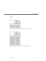
▼ Installing the Disk Shelf into the Rack Slide Rails
1
The Oracle Storage Drive Enclosure DE2-24P requires two standard mounting units (2RU) of
vertical space in the cabinet. Starting at the bottom of the cabinet, locate the appropriate rack
unit (RU) height, which is six rack holes. Install disk shelves below controllers to prevent rack
from tipping.
2
Install the rails into the cabinet.
For an unthreaded universal 19-inch or Sun Rack II cabinet:
a) Position the front rail location pegs fully inside the appropriate holes in the front of the rack.
The rail flange must be inside of the cabinet flange, and the rail label facing the inside of the
cabinet.
b) Insert and loosely tighten one screw through the front of the rack and into the top hole in the
rails.
38
Sun ZFS Storage 7120, 7320, and 7420 Appliance Installation Guide • December 2012 E38245–01
DE2 24P
c) Adjust the rail lengths to fit, and position the rear rail location pegs in the corresponding rear
rack holes.
d) Insert and loosely tighten one screw through the back of the rack and into the back of the
rails.
For a threaded universal 19-inch cabinet:
a) Use the T20 Torx driver to remove the rail location pegs from the front and rear of the rails.
Chapter 2 • Installation
39
DE2 24P
b) Use the supplied wrench to insert two pins into each end of the rails, in the same location
where the location pegs were removed.
c) Position the front of the rails inside the cabinet, with the rail flange inside of the cabinet
flange, and the rail label facing the inside of the cabinet. The pins should be fully located within
the rack holes.
d) Insert and loosely tighten one screw through the front of the rack and into the top hole in the
rails.
e) Adjust the rail lengths to fit, and locate the rear pins inside the corresponding rear rack holes.
40
Sun ZFS Storage 7120, 7320, and 7420 Appliance Installation Guide • December 2012 E38245–01
DE2 24P
f) Insert and loosely tighten one screw through the back of the rack and into the back of the rails.
3
Using a mechanical lift or two people, one at each side of the disk shelf, carefully lift and rest the
shelf on the bottom ledge of the left and right rails. Do not lift using the power supply with fan
Chapter 2 • Installation
41
DE2 24P
module handles.
42
4
Carefully slide the shelf into the rails until it is fully seated within the cabinet. Ensure that the
shelf is fully seated within the rails. If removing the shelf to reseat it, support it at all times.
5
Remove the disk shelf approximately 7.87 in. (200 mm).
6
Tighten all four screws that were previously inserted and loosely tightened in the rails.
7
Fully insert the disk shelf again, and check that the shelf is still fully seated within the rails.
8
Remove the front side caps, install one screw into each front side, and replace the caps.
Sun ZFS Storage 7120, 7320, and 7420 Appliance Installation Guide • December 2012 E38245–01
DE2 24P
9
10
Install one long patchlock screw per rail to secure the rear of the shelf to the rear of the rack.
Connect and apply power to the disk shelf as described in the next section.
Powering On the Disk Shelf
Ensure you have met the following electrical safety measures before applying power to the disk
shelf:
■
Provide a suitable power source with electrical overload protection to meet the power
supply input voltage range of 100-240 VAC, 50-60 Hz. The disk shelves are compatible with
100-120 VAC or 200-240 VAC sources. The power source must not be overloaded by the
total number of disk shelves in the cabinet. At full load, each DE2-24 draws 1,140W, and
each Sun Disk Shelf draws 912W.
■
The power source must provide a reliable earth connection for each disk shelf and the
cabinet.
■
Ensure that the power source is easily accessible because the power cord is the main
disconnect device for the disk shelf.
Chapter 2 • Installation
43
DE2 24P
1. Plug a power cord into each power supply with fan module.
2. Plug the other end of the power cords into the external power source for the cabinet.Note:
To guarantee redundancy, power cords must be connected to two separate and independent
power sources.
3. Apply power to the external power source.
4. Place the power supply on/off switches to the "I" on position.
5. Turn on the cabinet circuit breakers, if applicable.
6. After the disk shelf powers on, which could take several minutes, ensure that the system
power indicator on the front of the disk shelf is lit a steady green, and that each power supply
with fan module status indicator on the rear is lit a steady green. If not, power off the disk
shelf as described in the next section and reseat the faulted module. If the module status
indicator is not a steady green after module reinsertion, contact Oracle Customer Service.
7. Perform the software setup tasks as described in the storage controller installation guide.
Powering Off the Disk Shelf
Most disk shelf components are hot-swappable; you do not need to remove power when
replacing them. Do not remove a component if you do not have an immediate replacement. The
disk shelf must not be operated without all components in place.
Powering off or removing all SAS chains from a disk shelf will cause the controller(s) to panic to
prevent data loss, unless the shelf is part of an NSPF (no single point of failure) data pool. To
avoid this, shut down the controller(s) before decommissioning the shelf. For details on NSPF
profiles, see Profile Configuration.
44
Sun ZFS Storage 7120, 7320, and 7420 Appliance Installation Guide • December 2012 E38245–01
Sun Disk Shelf
1. Stop all input and output to and from the disk shelf.
2. Wait approximately two minutes until all disk activity indicators have stopped flashing.
3. Place the power supply on/off switches to the "O" off position.
4. Disconnect the power cords from the external power source for the cabinet.Note: All power
cords must be disconnected to completely remove power from the disk shelf.
See Also
■
Cabling Diagrams
Sun Disk Shelf
Precautions
Observe the following cautions when installing a Sun Disk Shelf into a rack using the rail
assembly in the bolt-on rack mount kit. Note that if your rack mount kit shipped with
installation instructions, use those instructions instead.
■
Always load equipment into a rack from the bottom up so that it will not become top-heavy
and tip over. Deploy the anti-tip bar to prevent the rack from tipping during equipment
installation.
■
Ensure that the temperature in the rack does not exceed the controller's maximum ambient
rated temperatures. Consider the total airflow requirements of all equipment installed in the
rack to ensure that the equipment is operated within its specified temperature range.
Prerequisites
Refer to the poster that shipped with the product or the following section for an overview of
your disk shelf.
■
Disk Shelf Overview - view component diagrams and specifications
Tools and Equipment Needed
To install the shelf, you need the following tools:
■
You will need a No. 2 Phillips head screwdriver that is a minimum of 4 inches long.
■
A mechanical lift is highly recommended because the chassis can weigh between 91-170 lbs.
(42-77kg). At least three people are required: two to install the shelf or controller and one
spotter to engage the rails.
Chapter 2 • Installation
45
Sun Disk Shelf
■
If a mechanical lift is not available, remove the power supplies, SIM boards and hard disk
drives to reduce the weight, see Disk Shelf Maintenance Procedures for instructions.
Use one of the following racks for the Sun Disk Shelf:
■
Sun Rack 900/1000 cabinet
■
Sun Fire cabinet
■
Sun StorEdge Expansion cabinet
■
Sun Rack II 1042/1242 cabinet
■
Any 19-inch wide, 4-post, EIA-compatible rack or cabinet with a front-to-back depth
between vertical cabinet rails of 61 cm to 91 cm (24 in. to 36 in.). The cabinet can have
threaded or unthreaded cabinet rails.
Position the rack where the shelf is to be installed adjacent to the rack where the controller is
installed, if separate. Stabilize the cabinet and lock the casters.
Tasks
Sun Disk Shelf Tasks
▼ Installing the Sun Disk Shelf into the Rack Slide Rails
1
46
Starting at the bottom of the cabinet, locate the appropriate rack unit (RU) height. Install Disk
Shelves below controllers to prevent rack from tipping. The Sun Disk Shelf requires four
standard mounting units (4RU) of vertical space in the cabinet.
Sun ZFS Storage 7120, 7320, and 7420 Appliance Installation Guide • December 2012 E38245–01
Sun Disk Shelf
2
If you are using a universal 19-inch or Sun Rack II cabinet, snap an M6 square cage nut into the
4U location where you will be installing the system. Install in the top and bottom holes.
3
Install appropriate rail plates in four locations on the rack (2 front and 2 back) by aligning the
two pins on the rail plate with holes on the cabinet rails.
Chapter 2 • Installation
47
Sun Disk Shelf
48
4
Insert M6 screws in the top and bottom holes of each rail plate and tighten (8 total places).
5
Install each rail by first aligning the front pins of the rack adapter plates with corresponding
holes in the front of the rail, then adjust the rail to fit the rack and insert the pins from the rear
rack adapter plates into the corresponding holes of the rail.
Sun ZFS Storage 7120, 7320, and 7420 Appliance Installation Guide • December 2012 E38245–01
Sun Disk Shelf
6
Install four 8-32 screws into the four remaining front and rear holes of each rack rail (16 total).
Chapter 2 • Installation
49
Sun Disk Shelf
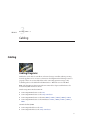
7
Using a mechanical lift or two people, one at each side of the shelf or controller, carefully lift and
rest the shelf on the bottom ledge of the left and right rails. The following graphic illustrates the
chassis insertion.
8
Carefully slide the shelf into the cabinet until the front flanges of the shelf touch the vertical
face of the rack.
9
Tighten the captive screws on each side of the front of the shelf to secure the shelf to the rack.
10
At the back of the disk shelf, slide a system locking clip onto each lower corner of the chassis.
See Also
■
50
Cabling Diagrams
Sun ZFS Storage 7120, 7320, and 7420 Appliance Installation Guide • December 2012 E38245–01
3
C H A P T E R
3
Cabling
Cabling
Cabling Diagrams
Disk shelves can be added to standalone or clustered storage controllers without powering
down the appliance or loss of service to clients. Use the diagrams in the following sections to
properly connect one or more disk shelves. After connecting expansion storage, verify
redundant paths to each disk shelf in the Maintenance > Hardware section of the BUI.
Note: The diagrams are abstractions and are not intended to depict actual hardware. Slot
locations may differ from those shown.
Oracle Storage Drive Enclosure DE2-24
■
Connecting DE2 Enclosures to the 7120
■
Connecting DE2 Enclosures to the 7320 | 7320 Cluster
■
Connecting DE2 Enclosures to the 7420: 2 HBAs | 3 HBAs | 4 HBAs | 5 HBAs | 6 HBAs
■
Connecting DE2 Enclosures to the 7420 Cluster: 2 HBAs | 3 HBAs | 4 HBAs | 5 HBAs | 6
HBAs
Sun Disk Shelf and J4x00
■
Connecting Disk Shelves to the 7120
■
Connecting Disk Shelves to the 7320 | 7320 Cluster
51
7120 Cabling
■
Connecting Disk Shelves to the 7420: 2 HBAs | 3 HBAs | 4 HBAs | 5 HBAs | 6 HBAs
■
Connecting Disk Shelves to the 7420 Cluster: 2 HBAs | 3 HBAs | 4 HBAs | 5 HBAs | 6 HBAs
Expanding storage may require adding another HBA to your configuration. To add an HBA for
a standalone controller, interrupt service and power down the appliance. For a clustered
configuration, you can power down each controller, reconnect to the new storage chain, and
power on individually with no interruption to service. Refer to the following sections for
procedures.
■
■
■
Expanding from 2 to 3 HBAs | 3 to 4 HBAs | 4 to 5 HBAs | 5 to 6 HBAs
7x20 Maintenance Procedures: PCIe Cards and Risers
7x10 Maintenance Procedures: PCIe Cards and Risers
To view cabling diagrams for legacy platforms, refer to the following online sections.
■
■
■
■
Connecting Expansion Storage to the 7210
Connecting Expansion Storage to the 7310 | 7310 Cluster
Connecting Expansion Storage to the 7410: 2 HBAs | 3 HBAs
Connecting Expansion Storage to the 7410 Cluster: 2 HBAs | 3 HBAs
7120 Cabling
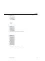
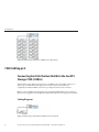
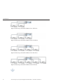
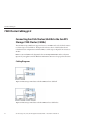
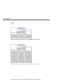
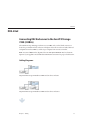
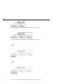
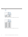
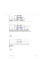
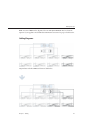
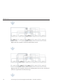
Connecting Sun Disk Shelves/J4x00s to the Sun ZFS
Storage 7120
The Sun ZFS Storage 7120 can support up to two disk shelves. The figures below show the
complete set of supported configurations, as well as steps to migrate from one state to another.
Note: Location of HBAs in the diagrams below are not representative. Refer to the PCIe
Options of your appliance model's Hardware Maintenance Overview for proper slot allocation.
Cabling Diagrams
fig.1 Sun ZFS Storage 7120 with one disk shelf
52
Sun ZFS Storage 7120, 7320, and 7420 Appliance Installation Guide • December 2012 E38245–01
7120 Cabling
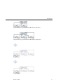
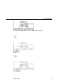
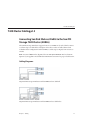
fig.2 Sun ZFS Storage 7120 with two disk shelves
Chapter 3 • Cabling
53
7320 Cabling
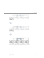
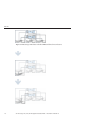
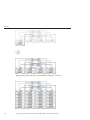
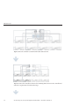
7320 Cabling
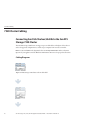
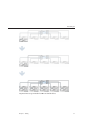
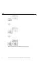
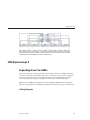
Connecting Sun Disk Shelves/J4x00s to the Sun ZFS
Storage 7320
The Sun ZFS Storage 7320 can support up to six disk shelves. The figures below show a subset of
supported configurations, as well as steps to migrate from one state to another.
Note: Location of HBAs in the diagrams below are not representative. Refer to the PCIe
Options of your appliance model's Hardware Maintenance Overview for proper slot allocation.
Cabling Diagrams
fig.1 Sun ZFS Storage 7320 with one disk shelf
54
Sun ZFS Storage 7120, 7320, and 7420 Appliance Installation Guide • December 2012 E38245–01
7320 Cabling
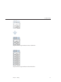
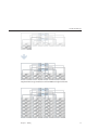
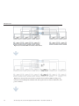
fig.2 Sun ZFS Storage 7320 with two disk shelves
fig.3 Sun ZFS Storage 7320 with six disk shelves
Chapter 3 • Cabling
55
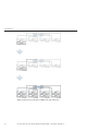
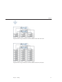
7320 Cluster Cabling
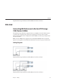
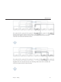
7320 Cluster Cabling
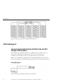
Connecting Sun Disk Shelves/J4x00s to the Sun ZFS
Storage 7320 Cluster
The Sun ZFS Storage 7320 cluster can support up to six disk shelves. The figures below show a
subset of supported configurations, as well as steps to migrate from one state to another.
Note: Location of HBAs in the diagrams below are not representative. Refer to the PCIe
Options of your appliance model's Hardware Maintenance Overview for proper slot allocation.
Cabling Diagrams
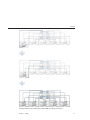
fig.1 Sun ZFS Storage 7320 cluster with one disk shelf
56
Sun ZFS Storage 7120, 7320, and 7420 Appliance Installation Guide • December 2012 E38245–01
7320 Cluster Cabling
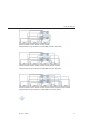
fig.2 Sun ZFS Storage 7320 cluster with two disk shelves
fig.3 Sun ZFS Storage 7320 cluster with six disk shelves
Chapter 3 • Cabling
57
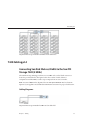
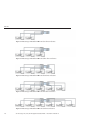
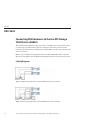
7420 Cabling pt.1
7420 Cabling pt.1
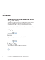
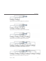
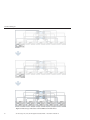
Connecting Sun Disk Shelves/J4x00s to the Sun ZFS
Storage 7420 (2 HBAs)
The Sun ZFS Storage 7420 supports from two to six HBA cards, each of which connects to a
chain of up to six disk shelves. The figures below show a subset of stable, balanced
configurations with two HBAs, as well as steps to migrate from one state to another.
Note: Location of HBAs in the diagrams below are not representative. Refer to the PCIe
Options of your appliance model's Hardware Maintenance Overview for proper slot allocation.
Cabling Diagrams
fig.1 Sun ZFS Storage 7420 with two HBAs and one disk shelf
fig.2 Sun ZFS Storage 7420 with two HBAs and two disk shelves
58
Sun ZFS Storage 7120, 7320, and 7420 Appliance Installation Guide • December 2012 E38245–01
7420 Cabling pt.1
fig.3 Sun ZFS Storage 7420 with two HBAs and four disk shelves
Chapter 3 • Cabling
59
7420 Cabling pt.2
fig.4 Sun ZFS Storage 7420 with two HBAs and 12 disk shelves
7420 Cabling pt.2
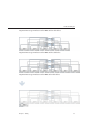
Connecting Sun Disk Shelves/J4x00s to the Sun ZFS
Storage 7420 (3 HBAs)
The Sun ZFS Storage 7420 supports from two to six HBA cards, each of which connects to a
chain of up to six disk shelves. The figures below show a subset of stable, balanced
configurations with three HBAs, as well as steps to migrate from one state to another.
Note: Location of HBAs in the diagrams below are not representative. Refer to the PCIe
Options of your appliance model's Hardware Maintenance Overview for proper slot allocation.
Cabling Diagrams
fig.1 Sun ZFS Storage 7420 with three HBAs and one disk shelf
60
Sun ZFS Storage 7120, 7320, and 7420 Appliance Installation Guide • December 2012 E38245–01
7420 Cabling pt.2
fig.2 Sun ZFS Storage 7420 with three HBAs and two disk shelves
fig.3 Sun ZFS Storage 7420 with three HBAs and three disk shelves
Chapter 3 • Cabling
61
7420 Cabling pt.3
fig.4 Sun ZFS Storage 7420 with three HBAs and six disk shelves
fig.5 Sun ZFS Storage 7420 with three HBAs and 18 disk shelves
7420 Cabling pt.3
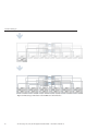
Connecting Sun Disk Shelves/J4x00s to the Sun ZFS
Storage 7420 (4 HBAs)
The Sun ZFS Storage 7420 supports from two to six HBA cards, each of which connects to a
chain of up to six disk shelves. The figures below show a subset of stable, balanced
configurations with four HBAs, as well as steps to migrate from one state to another.
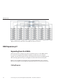
Note: Location of HBAs in the diagrams below are not representative. Refer to the PCIe
Options of your appliance model's Hardware Maintenance Overview for proper slot allocation.
62
Sun ZFS Storage 7120, 7320, and 7420 Appliance Installation Guide • December 2012 E38245–01
7420 Cabling pt.3
Cabling Diagrams
fig.1 Sun ZFS Storage 7420 with four HBAs and one disk shelf
fig.2 Sun ZFS Storage 7420 with four HBAs and two disk shelves
fig.3 Sun ZFS Storage 7420 with four HBAs and three disk shelves
fig.4 Sun ZFS Storage 7420 with four HBAs and four disk shelves
Chapter 3 • Cabling
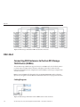
63
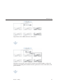
7420 Cabling pt.3
fig.5 Sun ZFS Storage 7420 with four HBAs and eight disk shelves
64
Sun ZFS Storage 7120, 7320, and 7420 Appliance Installation Guide • December 2012 E38245–01
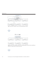
7420 Cabling pt.4
fig.6 Sun ZFS Storage 7420 with four HBAs and 24 disk shelves
7420 Cabling pt.4
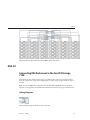
Connecting Sun Disk Shelves/J4x00s to the Sun ZFS
Storage 7420 (5 HBAs)
The Sun ZFS Storage 7420 supports from two to six HBA cards, each of which connects to a
chain of up to six disk shelves. The figures below show a subset of stable, balanced
configurations with five HBAs, as well as steps to migrate from one state to another.
Note: Location of HBAs in the diagrams below are not representative. Refer to the PCIe
Options of your appliance model's Hardware Maintenance Overview for proper slot allocation.
Cabling Diagrams
fig.1 Sun ZFS Storage 7420 with five HBAs and one disk shelf
Chapter 3 • Cabling
65
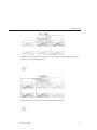
7420 Cabling pt.4
fig.2 Sun ZFS Storage 7420 with five HBAs and two disk shelves
fig.3 Sun ZFS Storage 7420 with five HBAs and three disk shelves
fig.4 Sun ZFS Storage 7420 with five HBAs and four disk shelves
fig.5 Sun ZFS Storage 7420 with five HBAs and five disk shelves
66
Sun ZFS Storage 7120, 7320, and 7420 Appliance Installation Guide • December 2012 E38245–01
7420 Cabling pt.4
fig.6 Sun ZFS Storage 7420 with five HBAs and 10 disk shelves
Chapter 3 • Cabling
67
7420 Cabling pt.5
fig.7 Sun ZFS Storage 7420 with five HBAs and 30 disk shelves
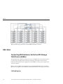
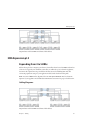
7420 Cabling pt.5
Connecting Sun Disk Shelves/J4x00s to the Sun ZFS
Storage 7420 (6 HBAs)
The Sun ZFS Storage 7420 supports from two to six HBA cards, each of which connects to a
chain of up to six disk shelves. The figures below show a subset of stable, balanced
configurations with six HBAs, as well as steps to migrate from one state to another.
Note: Location of HBAs in the diagrams below are not representative. Refer to the PCIe
Options of your appliance model's Hardware Maintenance Overview for proper slot allocation.
Cabling Diagrams
fig.1 Sun ZFS Storage 7420 with six HBAs and one disk shelf
68
Sun ZFS Storage 7120, 7320, and 7420 Appliance Installation Guide • December 2012 E38245–01
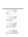
7420 Cabling pt.5
fig.2 Sun ZFS Storage 7420 with six HBAs and two disk shelves
fig.3 Sun ZFS Storage 7420 with six HBAs and three disk shelves
fig.4 Sun ZFS Storage 7420 with six HBAs and four disk shelves
fig.5 Sun ZFS Storage 7420 with six HBAs and five disk shelves
fig.6 Sun ZFS Storage 7420 with six HBAs and six disk shelves
Chapter 3 • Cabling
69
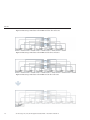
7420 Cabling pt.5
fig.7 Sun ZFS Storage 7420 with six HBAs and 12 disk shelves
70
Sun ZFS Storage 7120, 7320, and 7420 Appliance Installation Guide • December 2012 E38245–01
7420 Cluster Cabling pt.1
fig.8 Sun ZFS Storage 7420 with six HBAs and 36 disk shelves
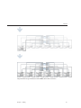
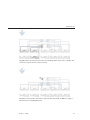
7420 Cluster Cabling pt.1
Connecting Sun Disk Shelves/J4x00s to the Sun ZFS
Storage 7420 Cluster (2 HBAs)
The Sun ZFS Storage 7420 cluster supports from two to six HBA cards, each of which connects
to a chain of up to six disk shelves. The figures below show a subset of stable, balanced and
redundant cluster configurations with two HBAs, as well as steps to migrate from one state to
another.
Note: Location of HBAs in the diagrams below are not representative. Refer to the PCIe
Options of your appliance model's Hardware Maintenance Overview for proper slot allocation.
Cabling Diagrams
fig.1 Sun ZFS Storage 7420 cluster with two HBAs and one disk shelf
Chapter 3 • Cabling
71
7420 Cluster Cabling pt.1
fig.2 Sun ZFS Storage 7420 cluster with two HBAs and two disk shelves
72
Sun ZFS Storage 7120, 7320, and 7420 Appliance Installation Guide • December 2012 E38245–01
7420 Cluster Cabling pt.1
fig.3 Sun ZFS Storage 7420 cluster with two HBAs and four disk shelves
fig.4 Sun ZFS Storage 7420 cluster with two HBAs and 12 disk shelves
Chapter 3 • Cabling
73
7420 Cluster Cabling pt.2
7420 Cluster Cabling pt.2
Connecting Sun Disk Shelves/J4x00s to the Sun ZFS
Storage 7420 Cluster (3 HBAs)
The Sun ZFS Storage 7420 cluster supports from two to six HBA cards, each of which connects
to a chain of up to six disk shelves. The figures below show a subset of stable, balanced and
redundant cluster configurations with three HBAs, as well as steps to migrate from one state to
another.
Note: Location of HBAs in the diagrams below are not representative. Refer to the PCIe
Options of your appliance model's Hardware Maintenance Overview for proper slot allocation.
Cabling Diagrams
fig.1 Sun ZFS Storage 7420 cluster with three HBAs and one disk shelf
fig.2 Sun ZFS Storage 7420 cluster with three HBAs and two disk shelves
74
Sun ZFS Storage 7120, 7320, and 7420 Appliance Installation Guide • December 2012 E38245–01
7420 Cluster Cabling pt.2
fig.3 Sun ZFS Storage 7420 cluster with three HBAs and three disk shelves
Chapter 3 • Cabling
75
7420 Cluster Cabling pt.2
fig.4 Sun ZFS Storage 7420 cluster with three HBAs and six disk shelves
fig.5 Sun ZFS Storage 7420 cluster with three HBAs and 18 disk shelves
76
Sun ZFS Storage 7120, 7320, and 7420 Appliance Installation Guide • December 2012 E38245–01
7420 Cluster Cabling pt.3
7420 Cluster Cabling pt.3
Connecting Sun Disk Shelves/J4x00s to the Sun ZFS
Storage 7420 Cluster (4 HBAs)
The Sun ZFS Storage 7420 cluster supports from two to six HBA cards, each of which connects
to a chain of up to six disk shelves. The figures below show a subset of stable, balanced and
redundant cluster configurations with four HBAs, as well as steps to migrate from one state to
another.
Note: Location of HBAs in the diagrams below are not representative. Refer to the PCIe
Options of your appliance model's Hardware Maintenance Overview for proper slot allocation.
Cabling Diagrams
fig.1 Sun ZFS Storage 7420 cluster with four HBAs and one disk shelf
fig.2 Sun ZFS Storage 7420 cluster with four HBAs and two disk shelves
Chapter 3 • Cabling
77
7420 Cluster Cabling pt.3
fig.3 Sun ZFS Storage 7420 cluster with four HBAs and three disk shelves
fig.4 Sun ZFS Storage 7420 cluster with four HBAs and four disk shelves
78
Sun ZFS Storage 7120, 7320, and 7420 Appliance Installation Guide • December 2012 E38245–01
7420 Cluster Cabling pt.3
fig.5 Sun ZFS Storage 7420 cluster with four HBAs and eight disk shelves
Chapter 3 • Cabling
79
7420 Cluster Cabling pt.4
fig.6 Sun ZFS Storage 7420 cluster with four HBAs and 24 disk shelves
7420 Cluster Cabling pt.4
Connecting Sun Disk Shelves/J4x00s to the Sun ZFS
Storage 7420 Cluster (5 HBAs)
The Sun ZFS Storage 7420 cluster supports from two to six HBA cards, each of which connects
to a chain of up to six disk shelves. The figures below show a subset of stable, balanced and
redundant cluster configurations with five HBAs, as well as steps to migrate from one state to
another.
Note: Location of HBAs in the diagrams below are not representative. Refer to the PCIe
Options of your appliance model's Hardware Maintenance Overview for proper slot allocation.
Cabling Diagrams
fig.1 Sun ZFS Storage 7420 cluster with five HBAs and one disk shelf
fig.2 Sun ZFS Storage 7420 cluster with five HBAs and two disk shelves
80
Sun ZFS Storage 7120, 7320, and 7420 Appliance Installation Guide • December 2012 E38245–01
7420 Cluster Cabling pt.4
fig.3 Sun ZFS Storage 7420 cluster with five HBAs and three disk shelves
fig.4 Sun ZFS Storage 7420 cluster with five HBAs and four disk shelves
fig.5 Sun ZFS Storage 7420 cluster with five HBAs and five disk shelves
Chapter 3 • Cabling
81
7420 Cluster Cabling pt.4
fig.6 Sun ZFS Storage 7420 cluster with five HBAs and 10 disk shelves
82
Sun ZFS Storage 7120, 7320, and 7420 Appliance Installation Guide • December 2012 E38245–01
7420 Cluster Cabling pt.5
fig.7 Sun ZFS Storage 7420 cluster with five HBAs and 30 disk shelves
7420 Cluster Cabling pt.5
Connecting Sun Disk Shelves/J4x00s to the Sun ZFS
Storage 7420 Cluster (6 HBAs)
The Sun ZFS Storage 7420 cluster supports from two to six HBA cards, each of which connects
to a chain of up to six disk shelves. The figures below show a subset of stable, balanced and
redundant cluster configurations with six HBAs, as well as steps to migrate from one state to
another.
Note: Location of HBAs in the diagrams below are not representative. Refer to the PCIe
Options of your appliance model's Hardware Maintenance Overview for proper slot allocation.
Cabling Diagrams
Chapter 3 • Cabling
83
7420 Cluster Cabling pt.5
fig.1 Sun ZFS Storage 7420 cluster with six HBAs and one disk shelf
fig.2 Sun ZFS Storage 7420 cluster with six HBAs and two disk shelves
fig.3 Sun ZFS Storage 7420 cluster with six HBAs and three disk shelves
84
Sun ZFS Storage 7120, 7320, and 7420 Appliance Installation Guide • December 2012 E38245–01
7420 Cluster Cabling pt.5
fig.4 Sun ZFS Storage 7420 cluster with six HBAs and four disk shelves
fig.5 Sun ZFS Storage 7420 cluster with six HBAs and five disk shelves
fig.6 Sun ZFS Storage 7420 cluster with six HBAs and six disk shelves
Chapter 3 • Cabling
85
7420 Cluster Cabling pt.5
fig.7 Sun ZFS Storage 7420 cluster with six HBAs and 12 disk shelves
86
Sun ZFS Storage 7120, 7320, and 7420 Appliance Installation Guide • December 2012 E38245–01
DE2-24
fig.8 Sun ZFS Storage 7420 cluster with six HBAs and 36 disk shelves
DE2-24
Connecting DE2 Enclosures to the Sun ZFS Storage
7120
The Sun ZFS Storage 7120 can support up to two DE2-24 drive enclosures. The figures below
show the complete set of supported configurations, as well as steps to migrate from one state to
another.
Note: Location of HBAs in the diagrams below are not representative. Refer to the PCIe
Options of your appliance model's Hardware Maintenance Overview for proper slot allocation.
Cabling Diagrams
fig.1 Sun ZFS Storage 7120 with one drive enclosure
Chapter 3 • Cabling
87
DE2-24
fig.2 Sun ZFS Storage 7120 with two drive enclosures
88
Sun ZFS Storage 7120, 7320, and 7420 Appliance Installation Guide • December 2012 E38245–01
DE2-24
DE2-24
Connecting DE2 Enclosures to the Sun ZFS Storage
7320
The Sun ZFS Storage 7320 can support up to six DE2-24 drive enclosures. The figures below
show a subset of supported configurations, as well as steps to migrate from one state to another.
Note: Location of HBAs in the diagrams below are not representative. Refer to the PCIe
Options of your appliance model's Hardware Maintenance Overview for proper slot allocation.
Cabling Diagrams
fig.1 Sun ZFS Storage 7320 with one drive enclosure
Chapter 3 • Cabling
89
DE2-24
fig.2 Sun ZFS Storage 7320 with two drive enclosures
fig.3 Sun ZFS Storage 7320 with six drive enclosures
90
Sun ZFS Storage 7120, 7320, and 7420 Appliance Installation Guide • December 2012 E38245–01
DE2-24
DE2-24
Connecting DE2 Enclosures to the Sun ZFS Storage
7320 Cluster
The Sun ZFS Storage 7320 cluster can support up to six DE2-24 drive enclosures. The figures
below show a subset of supported configurations, as well as steps to migrate from one state to
another.
Note: Location of HBAs in the diagrams below are not representative. Refer to the PCIe
Options of your appliance model's Hardware Maintenance Overview for proper slot allocation.
Cabling Diagrams
fig.1 Sun ZFS Storage 7320 cluster with one drive enclosure
Chapter 3 • Cabling
91
DE2-24
fig.2 Sun ZFS Storage 7320 cluster with two drive enclosures
fig.3 Sun ZFS Storage 7320 cluster with six drive enclosures
92
Sun ZFS Storage 7120, 7320, and 7420 Appliance Installation Guide • December 2012 E38245–01
DE2-24x2
DE2-24x2
Connecting DE2 Enclosures to the Sun ZFS Storage
7420 (2 HBAs)
The Sun ZFS Storage 7420 supports from two to six HBA cards, each of which connects to a
chain of up to six DE2-24 drive enclosures. The figures below show a subset of stable, balanced
configurations with two HBAs, as well as steps to migrate from one state to another.
Note: Location of HBAs in the diagrams below are not representative. Refer to the PCIe
Options of your appliance model's Hardware Maintenance Overview for proper slot allocation.
Cabling Diagrams
fig.1 Sun ZFS Storage 7420 with two HBAs and one drive enclosure
fig.2 Sun ZFS Storage 7420 with two HBAs and two drive enclosures
Chapter 3 • Cabling
93
DE2-24x2
fig.3 Sun ZFS Storage 7420 with two HBAs and four drive enclosures
94
Sun ZFS Storage 7120, 7320, and 7420 Appliance Installation Guide • December 2012 E38245–01
DE2-24x3
fig.4 Sun ZFS Storage 7420 with two HBAs and 12 drive enclosures
DE2-24x3
Connecting DE2 Enclosures to the Sun ZFS Storage
7420 (3 HBAs)
The Sun ZFS Storage 7420 supports from two to six HBA cards, each of which connects to a
chain of up to six DE2-24 drive enclosures. The figures below show a subset of stable, balanced
configurations with three HBAs, as well as steps to migrate from one state to another.
Note: Location of HBAs in the diagrams below are not representative. Refer to the PCIe
Options of your appliance model's Hardware Maintenance Overview for proper slot allocation.
Cabling Diagrams
fig.1 Sun ZFS Storage 7420 with three HBAs and one drive enclosure
Chapter 3 • Cabling
95
DE2-24x3
fig.2 Sun ZFS Storage 7420 with three HBAs and two drive enclosures
fig.3 Sun ZFS Storage 7420 with three HBAs and three drive enclosures
96
Sun ZFS Storage 7120, 7320, and 7420 Appliance Installation Guide • December 2012 E38245–01
DE2-24x4
fig.4 Sun ZFS Storage 7420 with three HBAs and six drive enclosures
fig.5 Sun ZFS Storage 7420 with three HBAs and 18 drive enclosures
DE2-24x4
Connecting DE2 Enclosures to the Sun ZFS Storage
7420 (4 HBAs)
The Sun ZFS Storage 7420 supports from two to six HBA cards, each of which connects to a
chain of up to six DE2-24 drive enclosures. The figures below show a subset of stable, balanced
configurations with four HBAs, as well as steps to migrate from one state to another.
Note: Location of HBAs in the diagrams below are not representative. Refer to the PCIe
Options of your appliance model's Hardware Maintenance Overview for proper slot allocation.
Chapter 3 • Cabling
97
DE2-24x4
Cabling Diagrams
fig.1 Sun ZFS Storage 7420 with four HBAs and one drive enclosure
fig.2 Sun ZFS Storage 7420 with four HBAs and two drive enclosures
fig.3 Sun ZFS Storage 7420 with four HBAs and three drive enclosures
fig.4 Sun ZFS Storage 7420 with four HBAs and four drive enclosures
98
Sun ZFS Storage 7120, 7320, and 7420 Appliance Installation Guide • December 2012 E38245–01
DE2-24x4
fig.5 Sun ZFS Storage 7420 with four HBAs and eight drive enclosures
Chapter 3 • Cabling
99
DE2-24x5
fig.6 Sun ZFS Storage 7420 with four HBAs and 24 drive enclosures
DE2-24x5
Connecting DE2 Enclosures to the Sun ZFS Storage
7420 (5 HBAs)
The Sun ZFS Storage 7420 supports from two to six HBA cards, each of which connects to a
chain of up to six DE2-24 drive enclosures. The figures below show a subset of stable, balanced
configurations with five HBAs, as well as steps to migrate from one state to another.
Note: Location of HBAs in the diagrams below are not representative. Refer to the PCIe
Options of your appliance model's Hardware Maintenance Overview for proper slot allocation.
Cabling Diagrams
fig.1 Sun ZFS Storage 7420 with five HBAs and one drive enclosure
100
Sun ZFS Storage 7120, 7320, and 7420 Appliance Installation Guide • December 2012 E38245–01
DE2-24x5
fig.2 Sun ZFS Storage 7420 with five HBAs and two drive enclosures
fig.3 Sun ZFS Storage 7420 with five HBAs and three drive enclosures
fig.4 Sun ZFS Storage 7420 with five HBAs and four drive enclosures
fig.5 Sun ZFS Storage 7420 with five HBAs and five drive enclosures
Chapter 3 • Cabling
101
DE2-24x5
fig.6 Sun ZFS Storage 7420 with five HBAs and 10 drive enclosures
102
Sun ZFS Storage 7120, 7320, and 7420 Appliance Installation Guide • December 2012 E38245–01
DE2-24x6
fig.7 Sun ZFS Storage 7420 with five HBAs and 30 drive enclosures
DE2-24x6
Connecting DE2 Enclosures to the Sun ZFS Storage
7420 (6 HBAs)
The Sun ZFS Storage 7420 supports from two to six HBA cards, each of which connects to a
chain of up to six DE2-24 drive enclosures. The figures below show a subset of stable, balanced
configurations with six HBAs, as well as steps to migrate from one state to another.
Note: Location of HBAs in the diagrams below are not representative. Refer to the PCIe
Options of your appliance model's Hardware Maintenance Overview for proper slot allocation.
Cabling Diagrams
fig.1 Sun ZFS Storage 7420 with six HBAs and one drive enclosure
Chapter 3 • Cabling
103
DE2-24x6
fig.2 Sun ZFS Storage 7420 with six HBAs and two drive enclosures
fig.3 Sun ZFS Storage 7420 with six HBAs and three drive enclosures
fig.4 Sun ZFS Storage 7420 with six HBAs and four drive enclosures
fig.5 Sun ZFS Storage 7420 with six HBAs and five drive enclosures
fig.6 Sun ZFS Storage 7420 with six HBAs and six drive enclosures
104
Sun ZFS Storage 7120, 7320, and 7420 Appliance Installation Guide • December 2012 E38245–01
DE2-24x6
fig.7 Sun ZFS Storage 7420 with six HBAs and 12 drive enclosures
Chapter 3 • Cabling
105
DE2-24x2
fig.8 Sun ZFS Storage 7420 with six HBAs and 36 drive enclosures
DE2-24x2
Connecting DE2 Enclosures to the Sun ZFS Storage
7420 Cluster (2 HBAs)
The Sun ZFS Storage 7420 cluster supports from two to six HBA cards, each of which connects
to a chain of up to six DE2-24 drive enclosures. The figures below show a subset of stable,
balanced and redundant cluster configurations with two HBAs, as well as steps to migrate from
one state to another.
Note: Location of HBAs in the diagrams below are not representative. Refer to the PCIe
Options of your appliance model's Hardware Maintenance Overview for proper slot allocation.
Cabling Diagrams
fig.1 Sun ZFS Storage 7420 cluster with two HBAs and one drive enclosure
106
Sun ZFS Storage 7120, 7320, and 7420 Appliance Installation Guide • December 2012 E38245–01
DE2-24x2
fig.2 Sun ZFS Storage 7420 cluster with two HBAs and two drive enclosures
Chapter 3 • Cabling
107
DE2-24x2
fig.3 Sun ZFS Storage 7420 cluster with two HBAs and four drive enclosures
fig.4 Sun ZFS Storage 7420 cluster with two HBAs and 12 drive enclosures
108
Sun ZFS Storage 7120, 7320, and 7420 Appliance Installation Guide • December 2012 E38245–01
DE2-24x3
DE2-24x3
Connecting DE2 Enclosures to the Sun ZFS Storage
7420 Cluster (3 HBAs)
The Sun ZFS Storage 7420 cluster supports from two to six HBA cards, each of which connects
to a chain of up to six DE2-24 drive enclosures. The figures below show a subset of stable,
balanced and redundant cluster configurations with three HBAs, as well as steps to migrate
from one state to another.
Note: Location of HBAs in the diagrams below are not representative. Refer to the PCIe
Options of your appliance model's Hardware Maintenance Overview for proper slot allocation.
Cabling Diagrams
fig.1 Sun ZFS Storage 7420 cluster with three HBAs and one drive enclosure
fig.2 Sun ZFS Storage 7420 cluster with three HBAs and two drive enclosures
Chapter 3 • Cabling
109
DE2-24x3
fig.3 Sun ZFS Storage 7420 cluster with three HBAs and three drive enclosures
110
Sun ZFS Storage 7120, 7320, and 7420 Appliance Installation Guide • December 2012 E38245–01
DE2-24x3
fig.4 Sun ZFS Storage 7420 cluster with three HBAs and six drive enclosures
fig.5 Sun ZFS Storage 7420 cluster with three HBAs and 18 drive enclosures
Chapter 3 • Cabling
111
DE2-24x4
DE2-24x4
Connecting DE2 Enclosures to the Sun ZFS Storage
7420 Cluster (4 HBAs)
The Sun ZFS Storage 7420 cluster supports from two to six HBA cards, each of which connects
to a chain of up to six DE2-24 drive enclosures. The figures below show a subset of stable,
balanced and redundant cluster configurations with four HBAs, as well as steps to migrate from
one state to another.
Note: Location of HBAs in the diagrams below are not representative. Refer to the PCIe
Options of your appliance model's Hardware Maintenance Overview for proper slot allocation.
Cabling Diagrams
fig.1 Sun ZFS Storage 7420 cluster with four HBAs and one drive enclosure
fig.2 Sun ZFS Storage 7420 cluster with four HBAs and two drive enclosures
112
Sun ZFS Storage 7120, 7320, and 7420 Appliance Installation Guide • December 2012 E38245–01
DE2-24x4
fig.3 Sun ZFS Storage 7420 cluster with four HBAs and three drive enclosures
fig.4 Sun ZFS Storage 7420 cluster with four HBAs and four drive enclosures
Chapter 3 • Cabling
113
DE2-24x4
fig.5 Sun ZFS Storage 7420 cluster with four HBAs and eight drive enclosures
114
Sun ZFS Storage 7120, 7320, and 7420 Appliance Installation Guide • December 2012 E38245–01
DE2-24x5
fig.6 Sun ZFS Storage 7420 cluster with four HBAs and 24 drive enclosures
DE2-24x5
Connecting DE2 Enclosures to the Sun ZFS Storage
7420 Cluster (5 HBAs)
The Sun ZFS Storage 7420 cluster supports from two to six HBA cards, each of which connects
to a chain of up to six DE2-24 drive enclosures. The figures below show a subset of stable,
balanced and redundant cluster configurations with five HBAs, as well as steps to migrate from
one state to another.
Note: Location of HBAs in the diagrams below are not representative. Refer to the PCIe
Options of your appliance model's Hardware Maintenance Overview for proper slot allocation.
Cabling Diagrams
fig.1 Sun ZFS Storage 7420 cluster with five HBAs and one drive enclosure
fig.2 Sun ZFS Storage 7420 cluster with five HBAs and two drive enclosures
Chapter 3 • Cabling
115
DE2-24x5
fig.3 Sun ZFS Storage 7420 cluster with five HBAs and three drive enclosures
fig.4 Sun ZFS Storage 7420 cluster with five HBAs and four drive enclosures
fig.5 Sun ZFS Storage 7420 cluster with five HBAs and five drive enclosures
116
Sun ZFS Storage 7120, 7320, and 7420 Appliance Installation Guide • December 2012 E38245–01
DE2-24x5
fig.6 Sun ZFS Storage 7420 cluster with five HBAs and 10 drive enclosures
Chapter 3 • Cabling
117
DE2-24x6
fig.7 Sun ZFS Storage 7420 cluster with five HBAs and 30 drive enclosures
DE2-24x6
Connecting DE2 Enclosures to the Sun ZFS Storage
7420 Cluster (6 HBAs)
The Sun ZFS Storage 7420 cluster supports from two to six HBA cards, each of which connects
to a chain of up to six DE2-24 drive enclosures. The figures below show a subset of stable,
balanced and redundant cluster configurations with six HBAs, as well as steps to migrate from
one state to another.
Note: Location of HBAs in the diagrams below are not representative. Refer to the PCIe
Options of your appliance model's Hardware Maintenance Overview for proper slot allocation.
Cabling Diagrams
118
Sun ZFS Storage 7120, 7320, and 7420 Appliance Installation Guide • December 2012 E38245–01
DE2-24x6
fig.1 Sun ZFS Storage 7420 cluster with six HBAs and one drive enclosure
fig.2 Sun ZFS Storage 7420 cluster with six HBAs and two drive enclosures
fig.3 Sun ZFS Storage 7420 cluster with six HBAs and three drive enclosures
Chapter 3 • Cabling
119
DE2-24x6
fig.4 Sun ZFS Storage 7420 cluster with six HBAs and four drive enclosures
fig.5 Sun ZFS Storage 7420 cluster with six HBAs and five drive enclosures
fig.6 Sun ZFS Storage 7420 cluster with six HBAs and six drive enclosures
120
Sun ZFS Storage 7120, 7320, and 7420 Appliance Installation Guide • December 2012 E38245–01
DE2-24x6
fig.7 Sun ZFS Storage 7420 cluster with six HBAs and 12 drive enclosures
Chapter 3 • Cabling
121
HBA Expansion pt.1
fig.8 Sun ZFS Storage 7420 cluster with six HBAs and 36 drive enclosures
HBA Expansion pt.1
Expanding from 2 to 3 HBAs
Follow the steps below to migrate your clustered controllers from two to three HBAs without
loss of service. To upgrade your standalone controller, you will need to power down the
appliance, disconnect the expansion storage, and follow the instructions for installing PCI cards
and connecting expansion storage to your appliance model, found elsewhere in this guide.
Note: Location of HBAs in the diagrams below are not representative. Refer to the PCIe
Options of your appliance model's Hardware Maintenance Overview for proper slot allocation.
Cabling Diagrams
122
Sun ZFS Storage 7120, 7320, and 7420 Appliance Installation Guide • December 2012 E38245–01
HBA Expansion pt.1
fig.1 Cluster with two HBAs and chains of disk shelves.
fig.2 Power down and disconnect the first controller, then install new HBA according to the
instructions on installing PCI cards.Rack and cable together the new chain of disk shelves, then
power on shelves.
Chapter 3 • Cabling
123
HBA Expansion pt.1
fig.3 Connect the controller to the second and third chain as shown.
fig.4 Reconnect the controller as shown to the remaining chains. Power on the controller and
wait for it to regain control of connected storage.
124
Sun ZFS Storage 7120, 7320, and 7420 Appliance Installation Guide • December 2012 E38245–01
HBA Expansion pt.1
fig.5 Power down and disconnect the second controller, then install new HBA according to
the instructions on installing PCI cards.
fig.6 Connect the controller to the second and third chain as shown.
Chapter 3 • Cabling
125
HBA Expansion pt.2
fig.7 Reconnect the controller as shown to the remaining chains. Power on the controller and
wait for it to regain control of connected storage.
fig.8 Cluster with three HBAs and chains of disk shelves.
HBA Expansion pt.2
Expanding from 3 to 4 HBAs
Follow the steps below to migrate your clustered controllers from three to four HBAs without
loss of service. To upgrade your standalone controller, you will need to power down the
appliance, disconnect the expansion storage, and follow the instructions for installing PCI cards
and connecting expansion storage to your appliance model, found elsewhere in this guide.
126
Sun ZFS Storage 7120, 7320, and 7420 Appliance Installation Guide • December 2012 E38245–01
HBA Expansion pt.2
Note: Location of HBAs in the diagrams below are not representative. Refer to the PCIe
Options of your appliance model's Hardware Maintenance Overview for proper slot allocation.
Cabling Diagrams
fig.1 Cluster with three HBAs and chains of disk shelves.
Chapter 3 • Cabling
127
HBA Expansion pt.2
fig.2 Power down and disconnect the first controller, then install new HBA according to the
instructions on installing PCI cards.Rack and cable together the new chain of disk shelves, then
power on shelves.
fig.3 Connect the controller to the third and fourth chain as shown.
128
Sun ZFS Storage 7120, 7320, and 7420 Appliance Installation Guide • December 2012 E38245–01
HBA Expansion pt.2
fig.4 Reconnect the controller as shown to the remaining chains. Power on the controller and
wait for it to regain control of connected storage.
fig.5 Power down and disconnect the second controller, then install new HBA according to
the instructions on installing PCI cards.
Chapter 3 • Cabling
129
HBA Expansion pt.2
fig.6 Connect the controller to the third and fourth chain as shown.
fig.7 Reconnect the controller as shown to the remaining chains. Power on the controller and
wait for it to regain control of connected storage.
130
Sun ZFS Storage 7120, 7320, and 7420 Appliance Installation Guide • December 2012 E38245–01
HBA Expansion pt.3
fig.8 Cluster with four HBAs and chains of disk shelves.
HBA Expansion pt.3
Expanding from 4 to 5 HBAs
Follow the steps below to migrate your clustered controllers from four to five HBAs without loss
of service. To upgrade your standalone controller, you will need to power down the appliance,
disconnect the expansion storage, and follow the instructions for installing PCI cards and
connecting expansion storage to your appliance model, found elsewhere in this guide.
Note: Location of HBAs in the diagrams below are not representative. Refer to the PCIe
Options of your appliance model's Hardware Maintenance Overview for proper slot allocation.
Cabling Diagrams
fig.1 Cluster with four HBAs and chains of disk shelves.
Chapter 3 • Cabling
131
HBA Expansion pt.3
fig.2 Power down and disconnect the first controller, then install new HBA according to the
instructions on installing PCI cards.Rack and cable together the new chain of disk shelves, then
power on shelves.
fig.3 Install new HBA according to the instructions on installing PCI cards, and connect the
controller to the first and third chain as shown.
132
Sun ZFS Storage 7120, 7320, and 7420 Appliance Installation Guide • December 2012 E38245–01
HBA Expansion pt.3
fig.4 Reconnect the controller as shown to the remaining chains. Power on the controller and
wait for it to regain control of connected storage.
fig.5 Power down and disconnect the second controller, then install new HBA according to
the instructions on installing PCI cards.
Chapter 3 • Cabling
133
HBA Expansion pt.3
fig.6 Connect the controller to the first and third chain as shown.
fig.7 Reconnect the controller as shown to the remaining chains. Power on the controller and
wait for it to regain control of connected storage.
134
Sun ZFS Storage 7120, 7320, and 7420 Appliance Installation Guide • December 2012 E38245–01
HBA Expansion pt.4
fig.8 Cluster with five HBAs and chains of disk shelves.
HBA Expansion pt.4
Expanding from 5 to 6 HBAs
Follow the steps below to migrate your clustered controllers from five to six HBAs without loss
of service. To upgrade your standalone controller, you will need to power down the appliance,
disconnect the expansion storage, and follow the instructions for installing PCI cards and
connecting expansion storage to your appliance model, found elsewhere in this guide.
Note: Location of HBAs in the diagrams below are not representative. Refer to the PCIe
Options of your appliance model's Hardware Maintenance Overview for proper slot allocation.
Cabling Diagrams
Chapter 3 • Cabling
135
HBA Expansion pt.4
fig.1 Cluster with five HBAs and chains of disk shelves.
fig.2 Power down and disconnect the first controller, then install new HBA according to the
instructions on installing PCI cards.Rack and cable together the new chain of disk shelves, then
power on shelves.
136
Sun ZFS Storage 7120, 7320, and 7420 Appliance Installation Guide • December 2012 E38245–01
HBA Expansion pt.4
fig.3 Install new HBA according to the instructions on installing PCI cards, and connect the
controller to the fourth and sixth chain as shown.
fig.4 Reconnect the controller as shown to the remaining chains. Power on the controller and
wait for it to regain control of connected storage.
Chapter 3 • Cabling
137
HBA Expansion pt.4
fig.5 Power down and disconnect the second controller, then install new HBA according to
the instructions on installing PCI cards.
fig.6 Connect the controller to the fourth and sixth chain as shown.
138
Sun ZFS Storage 7120, 7320, and 7420 Appliance Installation Guide • December 2012 E38245–01
HBA Expansion pt.4
fig.7 Reconnect the controller as shown to the remaining chains. Power on the controller and
wait for it to regain control of connected storage.
fig.8 Cluster with six HBAs and chains of disk shelves.
Chapter 3 • Cabling
139
140
4
C H A P T E R
4
Powering On and Configuring the System
Power
Powering On and Configuring the Appliance
This section provides instructions for configuring the primary network interface using the
preinstalled Sun ZFS Storage 7000 command line interface (CLI). After you configure the
primary interface, configure the remaining system parameters using the browser user interface
(BUI) from any client on the same network.
Prerequisites
Refer to the Installation section for detailed instructions to install your system in the rack.
Complete the system cabling according to the Cabling Diagrams section.
Gather the following information in preparation for configuring an Ethernet interface on the
storage controller.
■
■
■
■
■
■
■
IP address
IP netmask
Host name
Domain Name Server (DNS) domain name
DNS server IP address
Default router IP address
Password
If you will access the appliance through an administrative client, configure the administrative
client with the following settings:
■
■
■
8N1: eight data bits, no parity, one stop bit
9600 baud
Disable hardware flow control (CTS/RTS)
141
Power
■
Disable software flow control (XON/XOFF)
Refer to the Quick Setup poster that shipped with the product or the following sections for an
overview of your system controller.
■
■
■
7120 Overview
7320 Overview
7420 Overview
Connecting to ILOM
In rare cases, faults associated with uncorrectable CPU errors are not diagnosable or displayed
in the controller. These faults will be preserved by and observable on the ILOM. Connect to the
server ILOM (Service Processor) on the server platform to diagnose hardware faults that do not
appear in the BUI.
In a cluster environment, an ILOM connection should be made to each controller.
The server ILOM provides options for (i) network and (ii) serial port connectivity. Network
connection is the preferred choice, as the ILOM serial port does not always allow adequate
means of platform data collection.
WARNING : Failure to configure ILOM connectivity may lead to longer than necessary hardware
fault diagnosis and resolution times.
Tasks
Power Tasks
▼ Powering On the Appliance
You can access the system by connecting an administrative client to the serial management port
on the controller. Alternatively, if there is a Dynamic Host Configuration Protocol (DHCP)
server on the network, you can access the system by connecting the network management port
to your network.
Note that if you are installing a cluster, configure only one controller initially. The software
propagates the configuration to the peer controller during cluster initialization. After the cluster
is initialized, you can administer the system from either storage controller. However, do not
attempt initial configuration on both controllers independently. Refer to the Cluster
documentation for more information.
1
142
To perform initial configuration using serial, connect a serial cable from the SER MGT port on the
back panel of the controller to the serial port on the administrative client. Use a DB9 to RJ45
adapter if necessary.
Sun ZFS Storage 7120, 7320, and 7420 Appliance Installation Guide • December 2012 E38245–01
Power
2
To perform initial configuration using Ethernet, connect an Ethernet cable from the NET MGT
port on the back panel of the controller to your network.
3
Connect an Ethernet cable from your network to the NET0 port on the back panel of the
controller.
4
For 7120, 7320 and 7420, power on any disk shelves attached to the storage system by plugging
the two power cords into the universal power connectors, connecting the cords to the external
power source and turning on the disk shelf power switches. Wait several minutes until the
power indicators are lit a steady green.
5
For 7120, 7320 and 7420, connect power cables to power supply 0 and power supply 1 on the
storage controller(s) and wait until the Power/OK LED on the front panel next to the Power
button lights and remains lit (approximately two minutes).
6
Open a terminal window or terminal emulator and issue the appropriate command, as follows:
7
For a serial port concentrator connect (for example, using telnet), and use root as the user name
and replace serial-concentrator portnumber with the appropriate value, for example: telnet
serial-concentrator portnumber
8
For a network connection, connect using SSH and use root as the user name and determine the
IP address by accessing your DHCP server for the address assigned to the Service Processor MAC
address (see the label on the storage controller), for example: ssh [email protected]
9
Type the password changeme when prompted.
10
At the command prompt, type start /SP/console.
11
Type y to confirm that you want to start the console.
12
Press any key to begin configuring the appliance. The shell interface configuration screen
appears. NET-0 at the top of the screen should be underlined.
13
Verify the information on the screen, or enter values that do not appear.
14
Apply the values by pressing ESC-1 or the F1 key or by pressing Enter after confirming the
password. The final shell configuration screen appears, confirming that your appliance is ready
for further configuration using the BUI.
▼ Completing Configuration
Configure the remaining system parameters through the CLI after logging in, or through a
browser running on any client on the same network as the initial interface. The management
software is designed to be fully featured and functional on a variety of web browsers.
Chapter 4 • Powering On and Configuring the System
143
Initial
1
Direct your browser to the system using either the IP address or host name you assigned to the
NET0 port as follows: https://ipaddress:215 or https://hostname:215. The login screen appears.
2
Type root into the Username field and the administrative password that you entered into the
appliance shell kit interface and press the Enter key. The Welcome screen appears.
3
To begin configuring the system, click Start on the Welcome screen. You are guided through the
Initial Configuration of the remaining network interfaces, DNS, time settings, directory service
and storage.
Next Steps
■
Initial Configuration
Initial
Initial Configuration
The initial configuration consists of six configuration steps.
1.
2.
3.
4.
5.
144
Network
DNS
Time
Name Services (NIS, LDAP, Active Directory)
Storage
Sun ZFS Storage 7120, 7320, and 7420 Appliance Installation Guide • December 2012 E38245–01
Initial
6. Registration & Support
Prerequisites
The initial configuration of the system is conducted after powering it on for the first time and
establishing a connection, as documented in the Installation section.
Note that the option to perform initial configuration of a cluster is only available in the BUI. If
electing this option, read the clustering documentation before beginning initial configuration
for detailed additional steps that are required for successful cluster setup. Pay careful attention
to the Clustering Considerations for Networking section. Alternatively, cluster-capable
appliances may be initially configured for standalone operation using the following procedure,
and re-configured for cluster operation at a later time.
Summary
This procedure will configure networking connectivity, several client network services, and the
layout of the storage pool for standalone operation. When completed, the appliance is ready for
use - but will not have any shares configured for remote clients to access. To create shares or
revisit settings, refer to the Shares and Configuration sections.
This procedure may be repeated at a later time by clicking the "INITIAL SETUP" button on the
Maintenance > System screen or by entering the maintenance system setup context in the
CLI.
Chapter 4 • Powering On and Configuring the System
145
Initial
BUI
The BUI initial configuration is the preferred method and provides a screen for each of the
initial configuration steps.
Click Start to begin basic configuration of network, time directory and support services. Click
Commit to save the configuration and go to the next screen. Arrows beneath the Commit
button can be used to revisit previous steps, and change the configuration if desired.
Configuring Management Port
All standalone controllers should have at least one NIC port configured as a management
interface. Select the Allow Admin option in the BUI to enable BUI connections on port 215 and
CLI connections on ssh port 22.
All cluster installations should have at least one NIC port on each controller configured as a
management interface as described above. In addition, the NIC instance number must be
unique on each controller.
CLI
Alternatively, use the CLI to step through the initial configuration sections. Each step begins by
printing its help, which can be reprinted by typing help. Use the done command to complete
each step.
146
Sun ZFS Storage 7120, 7320, and 7420 Appliance Installation Guide • December 2012 E38245–01
Initial
Performing Initial Configuration with the CLI
Login using the password you provided during Installation:
caji console login: root
Password:
Last login: Sun Oct 19 02:55:31 on console
To setup your system, you will be taken through a series of steps; as the setup
process advances to each step, the help message for that step will be
displayed.
Press any key to begin initial configuration ...
In this example, the existing settings are checked (which were obtained from the DHCP server),
and accepted by typing done. To customize them at this point, enter each context (datalinks,
devices and interfaces) and type help to see available actions for that context. See the Network
section for additional documentation. Pay careful attention to the Clustering Considerations
for Networking section if you will configure clustering.
aksh: starting configuration with "net" ...
Configure Networking. Configure the appliance network interfaces. The first
network interface has been configured for you, using the settings you provided
at the serial console.
Subcommands that are valid in this context:
datalinks
=> Manage datalinks
devices
=> Manage devices
interfaces
=> Manage interfaces
help [topic]
=> Get context-sensitive help. If [topic] is specified,
it must be one of "builtins", "commands", "general",
"help" or "script".
show
=> Show information pertinent to the current context
abort
=> Abort this task (potentially resulting in a
misconfigured system)
done
=> Finish operating on "net"
caji:maintenance system setup net> devices show
Devices:
DEVICE
nge0
nge1
nge2
nge3
UP
true
false
false
false
MAC
0:14:4f:8d:59:aa
0:14:4f:8d:59:ab
0:14:4f:8d:59:ac
0:14:4f:8d:59:ad
SPEED
1000 Mbit/s
0 Mbit/s
0 Mbit/s
0 Mbit/s
caji:maintenance system setup net> datalinks show
Datalinks:
Chapter 4 • Powering On and Configuring the System
147
Initial
DATALINK CLASS
nge0 device
LINKS
nge0
LABEL
Untitled Datalink
caji:maintenance system setup net> interfaces show
Interfaces:
INTERFACE STATE CLASS LINKS
nge0 up
ip
nge0
ADDRS
192.168.2.80/22
LABEL
Untitled Interface
caji:maintenance system setup net> done
Refer to the DNS section for additional documentation about DNS.
Configure DNS. Configure the Domain Name Service.
Subcommands that are valid in this context:
help [topic]
=> Get context-sensitive help. If [topic] is specified,
it must be one of "builtins", "commands", "general",
"help", "script" or "properties".
show
=> Show information pertinent to the current context
commit
=> Commit current state, including any changes
abort
=> Abort this task (potentially resulting in a
misconfigured system)
done
=> Finish operating on "dns"
get [prop]
=> Get value for property [prop]. ("help properties"
for valid properties.) If [prop] is not specified,
returns values for all properties.
set [prop]
=> Set property [prop] to [value]. ("help properties"
for valid properties.) For properties taking list
values, [value] should be a comma-separated list of
values.
caji:maintenance system setup dns> show
Properties:
<status> = online
domain = sun.com
servers = 192.168.1.4
caji:maintenance system setup dns> set domain=sf.fishworks.com
domain = sf.fishworks.com (uncommitted)
caji:maintenance system setup dns> set servers=192.168.1.5
servers = 192.168.1.5 (uncommitted)
caji:maintenance system setup dns> commit
caji:maintenance system setup dns> done
aksh: done with "dns", advancing configuration to "ntp" ...
Configure Network Time Protocol (NTP) to synchronize the appliance time clock. See the NTP
section for additional documentation.
148
Sun ZFS Storage 7120, 7320, and 7420 Appliance Installation Guide • December 2012 E38245–01
Initial
Configure Time. Configure the Network Time Protocol.
Subcommands that are valid in this context:
help [topic]
=> Get context-sensitive help. If [topic] is specified,
it must be one of "builtins", "commands", "general",
"help", "script" or "properties".
show
=> Show information pertinent to the current context
commit
=> Commit current state, including any changes
abort
=> Abort this task (potentially resulting in a
misconfigured system)
done
=> Finish operating on "ntp"
enable
=> Enable the ntp service
disable
=> Disable the ntp service
get [prop]
=> Get value for property [prop]. ("help properties"
for valid properties.) If [prop] is not specified,
returns values for all properties.
set [prop]
=> Set property [prop] to [value]. ("help properties"
for valid properties.) For properties taking list
values, [value] should be a comma-separated list of
values.
caji:maintenance system setup ntp> set servers=0.pool.ntp.org
servers = 0.pool.ntp.org (uncommitted)
caji:maintenance system setup ntp> commit
caji:maintenance system setup ntp> done
aksh: done with "ntp", advancing configuration to "directory" ...
Refer to the NIS, LDAP and Active Directory sections for additional documentation.
Configure Name Services. Configure directory services for users and groups. You
can configure and enable each directory service independently, and you can
configure more than one directory service.
Subcommands that are valid in this context:
nis
=> Configure NIS
ldap
=> Configure LDAP
ad
=> Configure Active Directory
help [topic]
=> Get context-sensitive help. If [topic] is specified,
it must be one of "builtins", "commands", "general",
"help" or "script".
show
=> Show information pertinent to the current context
abort
=> Abort this task (potentially resulting in a
misconfigured system)
Chapter 4 • Powering On and Configuring the System
149
Initial
done
=> Finish operating on "directory"
caji:maintenance system setup directory> nis
caji:maintenance system setup directory nis> show
Properties:
<status> = online
domain = sun.com
broadcast = true
ypservers =
caji:maintenance system setup directory nis> set domain=fishworks
domain = fishworks (uncommitted)
caji:maintenance system setup directory nis> commit
caji:maintenance system setup directory nis> done
caji:maintenance system setup directory> done
aksh: done with "directory", advancing configuration to "support" ...
Configure storage pools that are characterized by their underlying data redundancy, and
provide space that is shared across all filesystems and LUNs. See the Storage section for
additional documentation.
Configure Storage.
Subcommands that are valid in this context:
help [topic]
=> Get context-sensitive help. If [topic] is specified,
it must be one of "builtins", "commands", "general",
"help", "script" or "properties".
show
=> Show information pertinent to the current context
commit
=> Commit current state, including any changes
done
=> Finish operating on "storage"
config <pool>
=> Configure the storage pool
unconfig
=> Unconfigure the storage pool
add
=> Add additional storage to the storage pool
import
=> Search for existing or destroyed pools to import
scrub <start|stop>
=> Start or stop a scrub
get [prop]
=> Get value for property [prop]. ("help properties"
for valid properties.) If [prop] is not specified,
returns values for all properties.
set pool=[pool]
=> Change current pool
caji:maintenance system setup storage> show
Properties:
pool = pool-0
status = online
profile = mirror
150
Sun ZFS Storage 7120, 7320, and 7420 Appliance Installation Guide • December 2012 E38245–01
Update
log_profile = cache_profile = caji:maintenance system setup storage> done
aksh: done with "storage", advancing configuration to "support" ...
Refer to (Phone Home) for additional documentation of remote support configuration.
Remote Support. Register your appliance and configure remote monitoring.
Subcommands that are valid in this context:
tags
=> Configure service tags
scrk
=> Configure phone home
help [topic]
=> Get context-sensitive help. If [topic] is specified,
it must be one of "builtins", "commands", "general",
"help" or "script".
show
=> Show information pertinent to the current context
abort
=> Abort this task (potentially resulting in a
misconfigured system)
done
=> Finish operating on "support"
caji:maintenance system setup support> done
aksh: initial configuration complete!
Update
Post-Installation Controller Update
Maintaining controller software in advance of putting your appliance into production enables
you to reap the greatest benefits of recent software enhancements. In many cases, a simple
software update will resolve an issue observed in testing or provide you with new enhancements
that improve productivity. Update storage controllers to the latest software and associated
firmware using the following process.
1. Ensure that any resilvering operations have completed by checking the Configuration >
Storage screen.
2. Ensure that there are no active problems on the Maintenance > Problems screen.
3. Verify that hardware firmware updates are not in progress on the Maintenance > System
screen.
4. Read the Release Notes associated with the software update and address any release-specific
prerequisites.
5. Click the "Sign In" link at http://support.oracle.com. (http://support.oracle.com.)
Chapter 4 • Powering On and Configuring the System
151
Update
The Oracle Single Sign-On screen appears.
6. Log in using your Oracle account credentials.
7. Download the desired software update.
The file is downloaded locally.
8. Unzip the downloaded file using an archive manager or by issuing the unzip command.
The file is expanded into the All_Supported_Platforms directory.
9. To upload and apply the update, use the Updating via the BUI or Updating via the CLI
procedures in the Maintenance > System online help page.
152
Sun ZFS Storage 7120, 7320, and 7420 Appliance Installation Guide • December 2012 E38245–01
Glossary
7110
Sun Storage 7110 Unified Storage System
7120
Sun ZFS Storage 7120
7210
Sun Storage 7210 Unified Storage System
7310
Sun Storage 7310 Unified Storage System
7320
Sun ZFS Storage 7320
7410
Sun Storage 7410 Unified Storage System
7420
Sun ZFS Storage 7420
Active Directory
Microsoft Active Directory server
Alerts
Configurable log, email or SNMP trap events
Analytics
appliance feature for graphing real-time and historic performance statistics
ARC
Adaptive Replacement Cache
BUI
Browser User Interface
CLI
Command Line Interface
Cluster
Multiple heads connected to shared storage
Controller
See ''Storage Controller''
CPU
Central Prcessing Unit
CRU
Customer Replaceable Component
Dashboard
appliance summary display of system health and activity
Dataset
the in-memory and on-disk data for a statistic from Analytics
DIMM
dual in-line memory module
Disk Shelf
the expansion storage shelf that is connected to the head node or storage controller
DNS
Domain Name Service
153
DTrace
DTrace
a comprehensive dynamic tracing framework for troubleshooting kernel and application problems on
production systems in real-time
FC
Fibre Channel
FRU
Field Replaceable Component
FTP
File Transfer Protocol
GigE
Gigabit Ethernet
HBA
Host Bus Adapter
HCA
Host Channel Adapter
HDD
Hard Disk Drive
HTTP
HyperText Transfer Protocol
Hybrid Storage
Pool
combines disk, flash, and DRAM into a single coherent and seamless data store.
Icons
icons visible in the BUI
IOM
I/O Module; similar to a SIM
iSCSI
Internet Small Computer System Interface
Kiosk
a restricted BUI mode where a user may only view one specific screen
L2ARC
Level 2 Adaptive Replacement Cache
LDAP
Lightweight Directory Access Protocol
LED
light-emitting diode
Logzilla
write IOPS accelerator
LUN
Logical Unit
Masthead
top section of BUI screen
Modal Dialog
a new screen element for a specific function
NFS
Network File System
NIC
Network Interface Card
NIS
Network Information Service
PCIe
Peripheral Component Interconnect Express
PCM
Power Cooling Module, consisting of a PSU and one or more fans
Pool
provide storage space that is shared across all filesystems and LUNs
154
Sun ZFS Storage 7120, 7320, and 7420 Appliance Installation Guide • December 2012 E38245–01
ZFS
Project
a collection of shares
PSU
Power Supply Unit, included with fans in a power cooling module (PCM)
QDR
quad data rate
Readzilla
read-optimized flash SSD for the L2ARC
Remote
Replication
replicating shares to another appliance
Rollback
reverts all of the system software and all of the metadata settings of the system back to their state just prior
to applying an update
SAS
Serial Attached SCSI
SAS-2
Serial Attached SCSI 2.0
SATA
Serial ATA
Schema
configurable properties for shares
Scripting
automating CLI tasks
Service
appliance service software
Share
ZFS filesystem shared using data protocols
SIM
SAS Interface Module
Snapshot
an image of a share
SSD
Solid State Drive
SSH
Secure Shell
Statistic
a metric visible from Analytics
Storage Controller the head node of the appliance
Support Bundle
auto-generated files containing system configuration information and core files for use by remote support
in debugging system failures
Title Bar
local navigation and function section of BUI screen
Updates
software or firmware updates
WebDAV
Web based Distributed Authoring and Versioning
ZFS
on-disk data storage subsystem
155
156