1
Planning for Large
Configuration of Netra™ t1
Server
By Stan Stringfellow - Special to Sun BluePrints™
OnLine
Sun BluePrints OnLine - January 2001
http://www.sun.com/blueprints
Sun Microsystems, Inc.
901 San Antonio Road
Palo Alto, CA 94303 USA
650 960-1300
fax 650 969-9131
Part No.: 806-6640-10
Revision 01, 01/10/01
Edition: January 2001
Copyright 2001 Sun Microsystems, Inc. 901 San Antonio Road, Palo Alto, California 94303 U.S.A. All rights reserved.
This product or document is protected by copyright and distributed under licenses restricting its use, copying, distribution, and decompilation.
No part of this product or document may be reproduced in any form by any means without prior written authorization of Sun and its licensors,
if any. Third-party software, including font technology, is copyrighted and licensed from Sun suppliers.
Parts of the product may be derived from Berkeley BSD systems, licensed from the University of California. UNIX is a registered trademark in
the U.S. and other countries, exclusively licensed through X/Open Company, Ltd.
Sun, Sun Microsystems, the Sun logo, Sun BluePrints, Netra, Sun Professional Services, Sun Enterprise, Starfire and Solaris are trademarks or
registered trademarks of Sun Microsystems, Inc. in the U.S. and other countries.
The OPEN LOOK and Sun™ Graphical User Interface was developed by Sun Microsystems, Inc. for its users and licensees. Sun acknowledges
the pioneering efforts of Xerox in researching and developing the concept of visual or graphical user interfaces for the computer industry. Sun
holds a non-exclusive license from Xerox to the Xerox Graphical User Interface, which license also covers Sun’s licensees who implement OPEN
LOOK GUIs and otherwise comply with Sun’s written license agreements.
RESTRICTED RIGHTS: Use, duplication, or disclosure by the U.S. Government is subject to restrictions of FAR 52.227-14(g)(2)(6/87) and
FAR 52.227-19(6/87), or DFAR 252.227-7015(b)(6/95) and DFAR 227.7202-3(a).
DOCUMENTATION IS PROVIDED “AS IS” AND ALL EXPRESS OR IMPLIED CONDITIONS, REPRESENTATIONS AND WARRANTIES,
INCLUDING ANY IMPLIED WARRANTY OF MERCHANTABILITY, FITNESS FOR A PARTICULAR PURPOSE OR NONINFRINGEMENT, ARE DISCLAIMED, EXCEPT TO THE EXTENT THAT SUCH DISCLAIMERS ARE HELD TO BE LEGALLY INVALID.
Copyright 2001 Sun Microsystems, Inc., 901 San Antonio Road, Palo Alto, Californie 94303 Etats-Unis. Tous droits réservés.
Ce produit ou document est protégé par un copyright et distribué avec des licences qui en restreignent l’utilisation, la copie, la distribution, et la
décompilation. Aucune partie de ce produit ou document ne peut être reproduite sous aucune forme, par quelque moyen que ce soit, sans
l’autorisation préalable et écrite de Sun et de ses bailleurs de licence, s’il y en a. Le logiciel détenu par des tiers, et qui comprend la technologie
relative aux polices de caractères, est protégé par un copyright et licencié par des fournisseurs de Sun.
Des parties de ce produit pourront être dérivées des systèmes Berkeley BSD licenciés par l’Université de Californie. UNIX est une marque
déposée aux Etats-Unis et dans d’autres pays et licenciée exclusivement par X/Open Company, Ltd.
Sun, Sun Microsystems, le logo Sun, Sun BluePrints, Netra, Sun Professional Services, Sun Enterprise, Starfire et Solaris sont des marques de
fabrique ou des marques déposées de Sun Microsystems, Inc. aux Etats-Unis et dans d’autres pays. Toutes les marques SPARC sont utilisées
sous licence et sont des marques de fabrique ou des marques déposées de SPARC International, Inc. aux Etats-Unis et dans d’autres pays. Les
produits portant les marques SPARC sont basés sur une architecture développée par Sun Microsystems, Inc.
L’interface d’utilisation graphique OPEN LOOK et Sun™ a été développée par Sun Microsystems, Inc. pour ses utilisateurs et licenciés. Sun
reconnaît les efforts de pionniers de Xerox pour la recherche et le développement du concept des interfaces d’utilisation visuelle ou graphique
pour l’industrie de l’informatique. Sun détient une licence non exclusive de Xerox sur l’interface d’utilisation graphique Xerox, cette licence
couvrant également les licenciés de Sun qui mettent en place l’interface d’utilisation graphique OPEN LOOK et qui en outre se conforment aux
licences écrites de Sun.
CETTE PUBLICATION EST FOURNIE "EN L’ETAT" ET AUCUNE GARANTIE, EXPRESSE OU IMPLICITE, N’EST ACCORDEE, Y COMPRIS
DES GARANTIES CONCERNANT LA VALEUR MARCHANDE, L’APTITUDE DE LA PUBLICATION A REPONDRE A UNE UTILISATION
PARTICULIERE, OU LE FAIT QU’ELLE NE SOIT PAS CONTREFAISANTE DE PRODUIT DE TIERS. CE DENI DE GARANTIE NE
S’APPLIQUERAIT PAS, DANS LA MESURE OU IL SERAIT TENU JURIDIQUEMENT NUL ET NON AVENU.
Please
Recycle
Planning for Large Configurations
of Netra™ t1 Servers
Scenario
Many service providers want to use large server farms for application front ends,
such as Web and cache services. This approach can result in benefits including cost
savings and easy incremental scaling, but it requires consideration of several key
issues regarding the manageability and serviceability of large numbers of servers
that may be geographically disbursed. In addition, this approach requires
consideration of power, cooling, and installation issues related to densely populated
racks of servers. This wide-ranging article addresses these topics and is intended to
assist Sun customers who want to deploy large server farms consisting of Netra™ t1
servers. Particular attention is given to the AC powered Netra t1 model 105 server.
Horizontal Scaling Issues
Horizontal scaling is most appropriate for applications that do not maintain session
state, such as Web servers. When an application does not maintain session state,
different servers can be assigned to handle requests from a single client during a
single session. This makes it easy to load balance user sessions efficiently across a
server farm. If an application maintains session state, it may be more difficult to
scale it across many servers and still use resources efficiently.
Since a large horizontally scaled solution necessarily consists of many individual
servers, by definition the system’s overall reliability is reduced. (Simply adding
more components increases the probability that some component will fail at any
given point in time.) Given that reliability is critical in service provider
environments, it is important to construct a server farm out of highly reliable
1
individual components. The Netra t1 server is popular among service providers in
part because of its inherent reliability and the fact that it is NEBS Level 3 certified (as
are all Netra server and storage products). Note, however, that Sun qualifies
individual Netra servers, not racks of servers.
Serviceability is another important consideration in any architecture where many
servers are deployed. The Netra servers feature back-end cabling and front-end
servicing. This allows field personnel to replace server components, such as disk
drives, quickly without detaching cables. The Netra t1 server is mounted with a
slide mechanism that allows the entire unit to be easily replaced (after uncabling it).
Thus, the server, itself, can be treated as a field replaceable unit (FRU). Note that the
Netra t1 server is factory shipped with the Solaris™ Operating Environment and the
Lights-Out Management (LOM) software pre-installed.
Floor space considerations also come into play when large numbers of servers are
deployed, especially in service provider environments which often must cope with
limited floor space. Densely packing servers into racks has proven to be a popular
solution to this problem. Sun’s most successful product in this space is the Netra t1
server which requires only one rack unit—or 1.75 inches—of rack height, and can fit
into shallow 600 mm deep cabinets.
Manageability of Server Farms
Manageability is a key consideration for any architecture that consists of a large
number of components, especially when the components are geographically
disbursed or when Lights-Out Management (LOM) facilities are setup and
maintained. This article examines a few important LOM datacenter manageability
issues.
Change Management
It is important to work out a strategy for upgrading or modifying many servers. To
choose an upgrade strategy, ask the following questions:
■
2
Will the application and operating system run successfully if you upgrade some
of the servers while the remaining servers continue to run older versions of the
software? If this is the case, it should be fairly easy to implement a procedure for
upgrading the entire server farm during off peak hours, perhaps over several
days. Generally, this upgrade strategy will work with server farms that use load
balancing mechanisms—a common approach in service provider front end
applications. Note that Netra servers are qualified to run the Solaris 2.6, 7, and 8
Operating Environments.
Planning for Large Configurations of Netra™ t1 Servers • January 2001
■
Is it possible to redirect user traffic to a secondary site while you upgrade the
primary site? If the secondary site offers reduced capacity, you must determine if
your service levels allow for degraded performance during the upgrade period.
Once the upgrade is complete, it should be a straightforward matter to redirect
user traffic back to the primary site.
■
If neither of the above approaches will work, can you shut down 50% of the
servers at your primary site and upgrade them, and then shut down the other
50% of the servers and upgrade them, all during a single offpeak period?
Because of change management requirements, there may come a point at which it
makes more sense to move up the vertical scaling curve. For example, you might
deploy your application across two-processor Netra t 1125 servers or four-processor
Netra t 1405 servers, instead of single-processor Netra t1 servers. However, your
application must be able to scale vertically (as well as horizontally) for this approach
to work.
Setting Up the LOM Serial Connector
The Netra t1 servers support Lights-Out Management (LOM) features, such as the
ability to remotely power a server on and off. The LOM functionality is accessed
over an RS-232 serial port that is available via an RJ45 connector on the back of the
unit. Altogether, there are four RJ45 connectors on the back of the unit, two of which
are 10/100 Mbps Ethernet ports with standard wiring pinouts, and two of which are
RS-232 serial ports. The LOM features are accessed via the Serial A port. The remote
console can be accessed via either the Serial A port or the Serial B port. If you are
using a remote console and LOM features, you should connect the remote console to
Serial B port, since its function is totally independent of the LOM facility.
To manage and monitor a Netra t1 system, you must use at least one of the serial
ports. You can connect either or both serial ports to any of the following devices:
■
A “dumb” terminal or a Sun workstation
For either or these purposes, you can use the standard RJ45 patch cable supplied
with the Netra t1 server, but you need to insert one end into the DB25 adapter
which is also supplied with the Netra t1 system.
■
A modem
For this connection, you can use the standard RJ45 patch cable supplied with the
Netra t1 server, but you must insert one end into the DB25 adapter which is also
supplied with the system. Do not connect a modem to the Serial A/LOM port;
use the Serial B port. The DTR signal that is asserted on the Serial A/LOM port
changes to DCD when the system is booted or when control of the port is given to
the LOM device, and this can cause modem connections to be lost. If you connect
the Serial A/LOM port to a Terminal Server, disable modem control on the
Terminal Server port.
Manageability of Server Farms
3
■
A Terminal Server (or patch panel connected to a Terminal Server)
The pinouts for the Netra t1 serial ports correspond to the pinouts for the RJ45
ports on the Asynchronous Serial Interface Breakout Cable supplied by Cisco for
use with the Cisco L2511 Terminal Server. For terminals from other
manufacturers, you may need to make your own cross-over (null-modem) cable.
The pinouts are shown in TABLE 1. For EMC compliance, all connectors or
connector adaptors must be shielded and must use metal housing construction.
If you are using a Cisco L2511 Terminal Server (and you are connecting the Netra t1
system to it using the Cisco Asynchronous Serial Interface Breakout Cable), you can
either connect the Breakout Cable directly to the Netra t1 server, or you can connect
the Breakout Cable to a patch panel and use the straight-through patch cable
(supplied by Sun) to connect the patch panel to the Netra t1 server.
You do not have to use the Netra t1 server with a Cisco Terminal Server. For other
Terminal Servers, check the manufacturer’s documentation to see if the pinouts of
the serial ports on the Terminal Server match the pinouts of the Netra t1 serial ports.
If they do not match, you must create a cable that directs each pin on one of the
Netra t1 serial ports to the corresponding pin in the Terminal Server’s serial port.
For your convenience, TABLE 1 provides the RJ45 pinouts, where Pin 1 is on the left if
the unit is viewed from the back.
TABLE 1
RJ45 Pinouts
PIN#
FUNCTION
1
RTS
2
DTR
3
TXD
4
Signal Ground
5
Signal Ground
6
RXD
7
DSR
8
CTS
The LOMlite Device
The Netra t1 server contains a built-in hardware component called the LOMlite
device. (The Netra t 1400/1405 servers also contain the built-in LOMlite device.) The
LOMlite device provides remote management of the system over the Serial A port.
The LOMlite device is powered by auxiliary power, so that you can monitor and
4
Planning for Large Configurations of Netra™ t1 Servers • January 2001
control the server even when it is powered off or when the operating system is not
running. When the operating system is running, LOMlite performs event reporting
via the Solaris Operating Environment over the Serial A/LOM port.
The LOMlite device monitors the status of the power supply unit (PSU) and fans in
the system. It provides a fault LED panel and three alarms to notify you of events or
failures. It also provides an automatic server restart (ASR) function, which can reset
the system in the event of a hard system hang. LOMlite provides the capability to
power up the system, to return it to standby mode, and to reset the host from the
serial command interface. Events such as fan failures and alarm state changes are
stored in an event log of ten events. The oldest fatal event is stored separately as the
most likely cause of subsequent failures. To avoid filling the event log with repeated
failures from a given source, only the first failure from any given source is stored.
After you clear the fault, you can re-enable monitoring of the failed device by
restoring standby power to the system—if the system was powered off to repair the
fault—or by issuing a check command at the LOMlite prompt. (The LOMlite
command line interface, which you can display on the console by entering a control
sequence, is beyond the scope of this article.) Re-enabling device monitoring also
clears the error indication on the fault LED. All device state changes are reported via
the interface to the Solaris Operating Environment, which provides additional
capacity for storing such events.
Netra t Alarms
The Netra servers support four separate alarms. One is the system alarm which
indicates whether or not the operating system is running. This alarm is reset
periodically by a UNIX® process called the watchdog. If the watchdog fails to fire, it
is an indication that the operating system has stopped running. The LOM hardware
notices failure, and if it is configured appropriately, it reboots the Netra t1 server.
The other three alarms are user-configurable, and are not tied into system resets.
These alarms are typically used by applications. For example, an application might
set an alarm condition if a daemon is not responding. In this case, remote
management software—possibly custom developed code—would notice that the
alarm condition has been set and take the appropriate action.
Note that there is no external physical alarm interface for the Netra t1 server, and no
relay contacts that attach to flashing lights. (Other Netra servers, including the Netra
t 1400/1405 server offer this feature.) The alarm conditions must be monitored by a
tool such as Sun™ Management Center software or a proprietary tool developed
using the API’s and scripts provided.
Manageability of Server Farms
5
Choosing a Management Approach
You have several options for taking advantage of the LOMlite technology in order to
remotely manage a large farm of Netra servers:
■
Use the provided UNIX utilities that interface with the Netra t Alarms/LOMlite
hardware. This is probably the best choice for most service providers, and it is the
approach that is examined in this article.
■
Write your own software programs using LOMlite UNIX ioctls. This provides
finer granularity of control and better performance. But this approach is much
more difficult to implement and it potentially ties you to a particular release of
the operating system. In addition, the performance benefits are probably not
critical for a “homegrown” remote management system.
■
Use Sun Management Center software. The Sun Management Center software
now provides support for Netra alarms and LOMlite features. To add this support
to an existing Sun Management Center installation, download the SunMC Netra
server packages from:
http://www.sun.com/netra/software
You will need to install the agent module (25 MBytes for the generic module plus
5 MBytes for the Netra server packages) on each Netra server to be monitored. In
addition, you will need to install the server module (45 MBytes for the generic
module plus 4 MBytes for the Netra server packages) on each server or console
that will perform monitoring tasks. For more information, see the Sun
Management Center 2.x Software User’s Guide and the Sun Management Center 2.x.x
Software Release Notes.
■
■
Use a third party systems management tool, such as HP Openview or Unicenter
TNG. It is unlikely you will use such a tool simply to manage a server farm.
However, if you have standardized on one of these tools to manage your
environment, you can now download the SNMP MIB package that allows the tool
to interface with the Netra alarms and LOMlite features. The package is located
at: http://www.sun.com/netra/software.
Support is also provided for BMC Patrol through Sun Professional Services SM.
If you choose to write scripts to monitor and manage your Netra t1 server farm, you
can call the system utilities shown in TABLE 2.
TABLE 2
6
Netra t Alarms & LOMlite System Utilities
tsalarm(7D)
Alarm device driver
tsctl(1M)
Controls alarms and watchdog
tsdog(1M)
Sets watchdog parameters & failure actions
tsmonitor(1M)
Simple example alarm monitor process
Planning for Large Configurations of Netra™ t1 Servers • January 2001
TABLE 2
Netra t Alarms & LOMlite System Utilities
tsstate(1M)
Gets state of PSU, fans, and watchdog clock
tsunlock(1M)
Enables detach requests for tsalarm driver
lomctl(1M)
Configure & control the LOMlite
lominfo(1M)
Returns environmental and configuration information
lomprog(1M)
Reprogram the LOMlite with new firmware
lom(7D)
LOM device driver
lomlited(1M)
Controls LOM alarms and watchdog
For a detailed description of these utilities, see the man pages that accompany the
Netra t Alarms/LOMlite software.
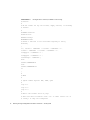
CODE EXAMPLE 1 provides an example Netra t Alarms/LOMlite control script. This
script uses the tsstate command within a loop which calls the function doalarm
in order to set Alarm1 upon any fault condition.
Manageability of Server Farms
7
CODE EXAMPLE 1
Example Netra t Alarms/LOMlite Control Script
#!/bin/sh
#
# We set alarm1 for any fan failure, supply failure, or watchdog
# failure.
#
TSSTATE="tsstate"
TSCTL="tsctl"
FAULTY="faulty"
MONALARM=alarm1
# Define a function to set alarm when anything is faulty
doalarm()
{
if [ "$fan1" = "$FAULTY" -o "$fan2" = "$FAULTY" -o \
"$fan3" = "$FAULTY" -o "$fan4" = "$FAULTY" -o \
"$supplya" = "$FAULTY" -o \
"$supplyb" = "$FAULTY" -o \
"$watchdog" = "$FAULTY" ]
then
$TSCTL $MONALARM=on
else
$TSCTL $MONALARM=off
fi
}
#
# MAIN
#
# Ignore common signals: HUP, INTR, QUIT
#
trap "" 1
trap "" 2
trap "" 3
#
# What’s the current state of play?
# This sets shell variables ’fan1’ etc. to their states ’ok’ or
# ’faulty’ if they are configured.
8
Planning for Large Configurations of Netra™ t1 Servers • January 2001
#
eval ‘$TSSTATE‘
if [ $? != 0 ]
then
# Can’t go on
exit $?
fi
#
# Set the initial alarm state
#
doalarm
#
# Now enter the loop, waiting for a change, and setting the alarm
# accordingly.
# Have to handle any combination of supported monitor bits, hence
# the long-winded parameter substitutions below. If this system
# monitor doesn’t report it, it isn’t configured.
#
while eval ‘$TSSTATE wait ${fan1:+fan1=$fan1} \
${fan2:+fan2=$fan2} \
${fan3:+fan3=$fan3} \
${fan4:+fan4=$fan4} \
${alarm3:+alarm3=$alarm3} \
${supplya:+supplya=$supplya} \
${supplyb:+supplyb=$supplyb} \
${watchdog:+watchdog=$watchdog}‘
do
doalarm
done
Manageability of Server Farms
9
Powering Densely Populated Racks
There are two Netra t1 models: the AC powered Netra t1 model 105 server, and the
DC powered Netra t1 model 100 server. The power supply unit is the only difference
between the two models. DC power is typically used in Telco environments, and AC
power is used in other service provider environments. Much of the information in
this section applies to both models, but the focus here is on the AC powered model,
since that model requires special power considerations.
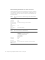
Calculating Power Requirements
You should determine your overall power requirements, and verify that your site
can support those power requirements. The power requirements for the individual
components within a Netra t1 server are shown in TABLE 3.
TABLE 3
Estimated Power Consumption for Netra t1 Components
Component
Estimated Power Consumption (at 100% PSU efficiency)
CPU 360 MHz
34.3 W
CPU 440MHz
36.3 W
Memory (per DIMM)
0.21 W per 64 MBytes
9 GByte (7200 rpm)
Disk Drive
11.0 W
18 GByte (10000 rpm)
Disk Drive
13.8 W
CD-ROM
3.2 W
PCI Card
Variable—25 W maximum
TABLE 3 assumes the power supply unit (PSU) is operating at 100% efficiency. You
should allow for 65% PSU efficiency. So, to determine a Netra t1 server’s total power
requirements, add together the figures from the table for each installed component
and divide the result by 0.65.
For example, assume a Netra t1 unit contains:
■
■
■
10
440 MHz CPU
512 Mbyte RAM
Two 9 Gbyte disk drives
Planning for Large Configurations of Netra™ t1 Servers • January 2001
You would calculate the unit’s power requirements as follows:
36.3 + (0.21 x 8) + (11.0 x 2) W
= 92.28 W
.65
To calculate the total power requirements for all servers installed in a rack, simply
add up the power requirement figures for the individual servers.
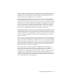
Applying Power to the Rack
This article focuses on the StorEdge 72” Expansion Cabinet, which provides 36 RU of
rack space and includes two AC power sequencers. It has the characteristics shown
in TABLE 4.
TABLE 4
StorEdge 72” Expansion Cabinet
Height
187 cm (73.5 inches)
Width
61 cm (24 inches)
Depth
93 cm (36.5 inches)
Weight
159 kg (350 lbs) empty
Power
220-240 VAC, 50-60 Hz
Watts
5,400 maximum
Amps
24
The 36 RU of rack space is over and above the space required by the power
sequencers. In theory, you could mount 36 Netra t1 servers in a single rack.
However, because of the power considerations (described below), it is recommended
that you mount a maximum of 32 Netra t1 servers in a single StorEdge 72”
Expansion Cabinet.
Each sequencer provides 10 AC outputs, as follows:
■
Two unswitched outputs. It is recommended that you do not use these outputs in
a rack of Netra t1 servers. For your information, however, one of the outputs is an
IEC320 AC outlet which is UL rated at 20 amps but European rated only at 16
amps. The second output is rated at 10 amps. Whenever power is applied, both of
these outputs are always on.
■
The Switched1 group consists of four outputs, each rated for 10 amps.
■
The Switched2 group also consists of four outputs, each rated for 10 amps.
Powering Densely Populated Racks
11
When you turn on the power sequencer with the key switch, all of the outputs in the
Switched1 group turn on immediately. After 30 seconds, all the outputs in the
Switched2 group turn on simultaneously.
Between the two power sequencers in a StorEdge 72” Expansion Cabinet, there are a
total of 16 AC outlets that you could use. If you want to mount 32 Netra t1 units in
the rack, you can attach splitter cables (part number 530-2264-01) to each of the 16
outputs, thereby providing 32 AC power sources. Thus, each power sequencer
provides power to a maximum of 16 Netra t1 servers.
This configuration is used successfully by many of Sun’s customers. However, there
are some issues that you should be aware of.
First, you may only be able use this maximum configuration with high-line voltage
(180 to 240 volts). Consider TABLE 5 which shows an example of the measured amps
and watts drawn by a Netra t1 server under different input voltages. These
measurements were taken by Sun personnel.
TABLE 5
Netra t1 Model 105 Server Amperes and Watts
Input Voltage
Amperes
Watts
90
0.95
85.6
100
0.85
84.5
120
0.70
84.5
180
0.51
82.6
200
0.46
81.7
240
0.39
81.9
Despite these particular measurements, the rated current for a Netra t1 server is 1.5
amps at 100VAC. This is a conservative value, but it is worth examining the
implications.
Each power sequencer is rated for a maximum of 24 amps. In the configuration we
are considering, 16 Netra t1 servers are connected to a single power sequencer. This
poses no problem in the 180VAC to 240VAC range. For example, at 240VAC, the total
amps requirement is 16 x 0.39 = 6.24 amps, which is less than 24 amps. However,
using the (admittedly conservative) 1.5 amp rating for 100VAC, the calculation is 16
x 1.5 = 24 amps, which is the maximum rating for the sequencer. Note that this does
not include the current required for the rack’s fan unit, if installed.
Another issue to consider is related to the potential in-rush current. When a server is
initially powered on, a transient spike occurs in the level of current as the capacitors
are charged within the power supply. This high current level decays very quickly—
generally in less than 200 milliseconds. The exact amount of current varies,
depending on when the power is applied with respect to the AC power cycle. The
12
Planning for Large Configurations of Netra™ t1 Servers • January 2001
in-rush current is maximized if power is applied at the point where the positive or
negative voltage is at it’s greatest value. The in-rush current is minimized if power is
applied at the zero-crossing point, when the voltage is momentarily at zero. AC
power generally goes through this cycle at 50 to 60 Hz.
The potential maximum amount of in-rush current for a Netra t1 server depends
upon how long the unit has been turned off. A cold start occurs when the unit has
been powered off for about one minute or longer. A warm start occurs when the unit
has been powered off for less than about one minute, for example if the power goes
off and comes back on within 50mS. The maximum in-rush current for a Netra t1
server is 56 amps upon a cold start, and 100 amps upon a warm start. Note that
these numbers are significantly higher than the nominal steady state current for a
Netra t1 server, which tends to be less than one amp, as shown above.
It is possible for in-rush current to open circuit breakers. In the configuration we are
discussing, eight Netra t1 servers are powered on simultaneously. If this occurs as a
warm start (e.g. if the AC power goes off and comes back on automatically within
50mS), and if the power is applied at the point where in-rush current is maximized,
a transient current of 800 amps could occur. This could potentially open a circuit
breaker on the wall.
This issue may or may not be important for a particular site. In many environments,
the service levels would permit you to simply wait a minute or so, and then turn on
the power sequencers with the key switches. However, if you have high availability
requirements and are using full racks of Netra t1 servers, you may need to consider
this issue. One potential solution is to use a power sequencer (or similar unit) that
always applies power when the AC voltage is at the zero-crossing point. You can
obtain such a unit from a third party supplier.
The circuit breakers in the power sequencers supplied with the StorEdge 72”
Expansion Cabinet allow only 360 amps of in-rush current. If you are using these
power sequencers, and if your service level agreements call for very high
availability, it is recommended that you attach only six Netra t1 units to each power
sequencer, without using splitter cables. Three units should be attached to the
Switched1 group, and three units should be attached to the Switched2 group. In this
situation, if three Netra t1 units are powered on simultaneously, the maximum inrush current should never exceed 300 amps.
Powering Densely Populated Racks
13
Electrical Requirements for Netra t1 Server
The following tables show the electrical requirements for the Netra t1 model 100
server and Netra t1 model 105 server. This information is included here for your
convenience since some of the values shown have not yet been published in the
Netra documentation.
TABLE 6
Voltage (V)
100 VAC
Current (A)
1.0 A
Power (W)
100 W
In-rush current (A)
at 264 VAC (warm
start)
Less than 100A decaying to normal in 200 msec.
Rated current of
system
1.5 A
Rated voltage of
system
100/240 VAC (Nominal)
TABLE 7
14
Netra t1 model 105 server—Maximum Design Values at Rated Nominal
Voltage
Netra t1 model 105 server—Measured Values
Configuration
1 440 MHz CPU
1 GByte memory (4 memory modules)
1 CD-ROM
2 1" 18 GByte, 10K rpm disk drive
1 PCI Card (QFE)
Running Sun VTS
Voltage (V)
100 VAC
Current (A)
0.85A
Power (W)
84.5 W
In-rush current (A)
at 264 VAC (cold
start)
56 A for less than 5 msec, decaying to 1A in less than 20 msec.
Planning for Large Configurations of Netra™ t1 Servers • January 2001
TABLE 8
Netra t1 model 100 server—Maximum Design Values at Rated Nominal
Voltage
Voltage (V)
-48 VDC
Current (A)
2.1 A
Power (W)
100 W
In-rush current (A)
at -75 VDC (cold
start)
Less than 20 A decaying to normal in 200 msec.
Rated current of
system
2.5 A
Rated voltage of
system
-48 / -60 VDC (Nominal)
TABLE 9
Netra t1 model 100 server—Measured Values
Configuration
1 440MHz CPU
1 GByte Memory (4 memory Modules)
1 CD-ROM
2 1" 18GByte, 10K rpm disk drives
1 PCI Card (QFE)
Running Sun VTS
Voltage (V)
-48 VDC
Current (A)
1.63 A
Power (W)
78 W
In-rush current (A)
at -75 VDC (cold
start)
7.32 A, decaying to 3 A in less than 25 msec.
Cooling Issues
All Netra servers use front-to-back cooling. These are known as Type A devices.
Some products from Sun, such as the Sun Enterprise™ 4500 server, use side-to-side
cooling. These are known as Type B devices. Front-to-back cooling is more efficient,
and makes it much easier to mount many devices in a single rack without
encountering cooling problems.
If you intend to mount 32 Netra t1 servers in a 36U StorEdge 72” Expansion Cabinet,
the left over 4U of cabinet space should be trimmed off with panels. This prevents
warm air from flowing to the front of the rack and being recirculated, which would
Cooling Issues
15
reduce the efficiency of the cooling system and potentially contribute to overheating
problems. Panels for the StorEdge 72” Expansion Cabinet are available in a variety
sizes, such as 1U, 2U, 3U, 4U, and 5U.
You may want to order the optional redundant fan tray cooling package (x-option
X9819A) that can be housed at the top of the StorEdge 72” Expansion Cabinet. The
fans pull air upward through the top of the rack. If space is limited at the rear of
your rack, it may be important to use a fan so that heat does not build up there. The
fan unit does not require any rack space.
You should calculate the overall heat generated by your racks so that you can size
your cooling system appropriately. To do this, simply convert the power
requirements figure (described in “Calculating Power Requirements, above) from
Watts to BTU/hour by multiplying the Watts figure by 3.415. For example, if a rack
requires 92.28 W, the heat dissipated is 92.28 x 3.415 = 315.14 BTU/hour.
Be sure to arrange your racks so that the warm air exhaust from one rack does not
flow directly into the cool air intake area for another rack. Any configuration you
select must be tested and qualified to pass performance and agency regulations,
including EMI.
Rackmount Installation
In addition to the StorEdge 72” Expansion Cabinet, Sun also offers the following
rackmount kits:
TABLE 10
16
Netra Rackmount Kits
X6919A
Netra Telco 19" conversion kit, for industry 72" rack 36U allowed
30U recommended
X6966A
Netra Telco 23" conversion kit, for industry 72" rack 36U allowed
30U recommended
X6967A
Netra Telco 24" conversion kit, for industry 72" rack 36U allowed
30U recommended
X6968A
600mm rack conversion kit
Planning for Large Configurations of Netra™ t1 Servers • January 2001
To mount a Netra t1 or Netra st D130 (one RU storage unit) into one of these racks,
you need one of the following rack mounting kits:
TABLE 11
Netra t1 server (or Netra st D130 storage unit) Rack Mounting Kit for
StorEdge 72” Expansion Cabinet
Description
Quantity
Part No.
Front slide
2
340-6215
Rear slide
2
340-6234
Cable bracket
1
340-6151
Thumbscrew bracket
2
340-6085
M4 8mm Phillips countersunk screw
4
240-3070
10-32 UNF screws
8
240-1207
M4 nut
4
240-1373
TABLE 12
Netra t1 server (or Netra st D130 storage unit) 19-inch Rack Mounting Kit
Description
Quantity
Part No.
Front slide
2
340-6215
Rear slide
2
340-6234
Cable bracket
1
340-6151
Thumbscrew bracket
2
340-6085
M4 8mm Phillips countersunk screw
4
240-3070
10-32 UNF screws
8
240-1207
M4 nut
4
240-1373
TABLE 13
Netra t1 server (or Netra st D130 storage unit) 23-inch Rack Mounting Kit
Description
Quantity
Part No.
Front slide
2
340-6209
Rear slide
2
340-6210
Cable bracket
1
340-6151
Thumbscrew bracket
2
340-6085
M4 8mm Phillips countersunk screw
4
240-3070
10-32 UNF screws
8
240-1207
M4 nut
4
240-1373
Rackmount Installation
17
TABLE 14
Netra t1 server (or Netra st D130 storage unit) 24-inch Rack Mounting Kit
Description
Quantity
Part No.
Front slide
2
340-6211
Rear slide
2
340-6212
Cable bracket
1
340-6151
Thumbscrew bracket
2
340-6085
M4 8mm Phillips countersunk screw
4
240-3070
10-32 UNF screws
8
240-1207
M4 nut
4
240-1373
TABLE 15
Netra t1 server (or Netra st D130 storage unit) 600mm Rack Mounting Kit
Description
Quantity
Part No.
Front slide
2
340-6213
Rear slide
2
340-6214
Cable bracket
1
340-6151
Thumbscrew bracket
2
340-6085
M4 8mm Phillips countersunk screw
4
240-3070
10-32 UNF screws
8
240-1207
M4 nut
4
240-1373
The cable bracket is provided to aid cable management at the rear of the system. It is
recommended that you mount units from the bottom of the rack to the top for
maximum stability. For step-by-step instructions on how to rackmount a Netra t1
server or a Netra st D130 storage unit, see the Netra t1 and Netra st D130 Rackmount
Installation guide, part number 806-3856-11.
18
Planning for Large Configurations of Netra™ t1 Servers • January 2001
Conclusion
This article examined several key remote management issues for server farms
consisting of Netra t1 servers. The Netra t Alarms/LOMlite facilities were
introduced, including the LOMlite automatic server restart (ASR) function and the
watchdog process. This article examined the best ways to use these facilities to
monitor and manage servers, and provided a sample script that makes calls to
Netra t Alarms/LOMlite system utilities.
Consideration was also given to the power, cooling, and rack mounting issues that
are involved with deploying densely populated racks of Netra t1 servers. Particular
attention was paid to the effects of “in-rush” current during warm and cold starts
and the importance of properly sizing the power sequencer capacity.
Acknowledgements
Warren Reid contributed to the article. Thanks to Cari Yuen, Sean Wrycraft, Bill
Channell, David Machado, Neil Bird, Peter Wilson, Raj Natarajan, Chin Cheng,
Richard Elling, John S. Howard, Mark Garner, and Bill Sprouse for their guidance
and reviews.
Author’s Bio: Stan Stringfellow
Stan Stringfellow is an independent author, technical writer and software developer who is currently
doing work for the Sun BluePrints™ program. He holds a B.A.C.S. from UC San Diego and has
written many manuals including the original software manuals for the Sun Enterprise 10000 (also
known as Starfire™) server. He may be contacted at [email protected].
Conclusion
19