1
Sun Sparc Enterprise MX000 Servers
TDC008
Sun Proprietary and Confidential
Sun Sparc Enterprise MX000
Servers
Technical Development Centre
Version 2.1
Page 1 of 327
Copyright © Sun Microsystems Ltd., 2008
Sun Proprietary and Confidential
Issue Date : August 2008
Sun Sparc Enterprise MX000 Servers
TDC008
Sun Proprietary and Confidential
Table of Contents
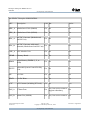
Facts at a Glance: ..........................................................................................................................10
M4000/M5000 Product Overview......................................................................................................12
Sun SPARC Enterprise M4000 Details:........................................................................................15
Sun SPARC Enterprise M5000 Details:........................................................................................21
SPARC Enterprise M4000 Server ............................................................................................26
SPARC Enterprise M5000 Server.............................................................................................29
Operator Panel Overview..........................................................................................................32
Components...................................................................................................................................36
Motherboard Unit......................................................................................................................40
CPU Module.............................................................................................................................41
Memory Board..........................................................................................................................44
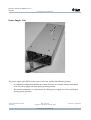
Fan.............................................................................................................................................48
Power Supply............................................................................................................................50
Operator Panel...........................................................................................................................53
eXtended System Control Facility Unit (XSCFU)...................................................................54
I/O Unit.....................................................................................................................................57
On-Board Drive Units ..............................................................................................................59
Hard Disk Drive...................................................................................................................61
DVD Drive ..........................................................................................................................61
.............................................................................................................................................61
Tape Drive Unit ...................................................................................................................62
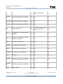
I/O Options....................................................................................................................................63
External I/O Expansion Unit.....................................................................................................63
PCI Cards..................................................................................................................................65
PCI Cassette..............................................................................................................................66
Software Features..........................................................................................................................67
M4000 Server Components................................................................................................................68
M5000 Server Components................................................................................................................71
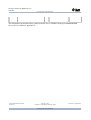
M8000/M9000 Product Overview......................................................................................................74
SPARC Enterprise M8000 Server Appearance
M9000 Server (Base
Cabinet Only) Appearance..............................................................................................75
SPARC Enterprise M9000 Server (With an Expansion Cabinet) Appearance ..............75
Sun SPARC Enterprise M8000 Details:........................................................................................76
Sun SPARC Enterprise M9000-32 Details:...................................................................................82
Sun SPARC Enterprise M9000-64 Details:...................................................................................88
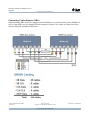
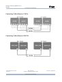
M8000 Power connections...................................................................................................94
M8000 Server Components......................................................................................................96
M9000 Server Components (Base Cabinet Only) ....................................................................98
M9000 Server Components (With an Expansion Cabinet) ......................................................99
Technical Development Centre
Version 2.1
Page 2 of 327
Copyright © Sun Microsystems Ltd., 2008
Sun Proprietary and Confidential
Issue Date : August 2008
Sun Sparc Enterprise MX000 Servers
TDC008
Sun Proprietary and Confidential
Operator Panel Overview........................................................................................................100
Operator Panel Appearance...........................................................................................100
Operator Panel LEDs.....................................................................................................100
Operator Panel Switches ...............................................................................................101
Server Components......................................................................................................................102
CPU Module...........................................................................................................................102
CPU/Memory Board Unit.......................................................................................................103
Memory DIMM and CPU Locations......................................................................................104
CMU locations........................................................................................................................105
I/O Unit...................................................................................................................................107
IOU slot locations...................................................................................................................108
IOU Locations.........................................................................................................................109
FAN Unit.................................................................................................................................111
Fan Backplane Locations........................................................................................................112
Power Supply Unit..................................................................................................................114
PSU Locations by Server........................................................................................................115
Crossbar Unit..........................................................................................................................116
XBU Locations.......................................................................................................................117
Connecting Cables Between XBUs........................................................................................118
Connecting Cables Between CLKUs......................................................................................119
Connecting Cables Between XSCFUs....................................................................................119
Clock Control Unit..................................................................................................................120
Operator Panel.........................................................................................................................121
Operating Panel LEDs............................................................................................................121
Operator Panel Keyswitch......................................................................................................122
XSCF Unit...............................................................................................................................123
Internal Drive Units................................................................................................................124
Hard Disk Drive.............................................................................................................124
DVD-ROM Drive Unit/Tape Drive Unit.......................................................................124
Media Backplane.....................................................................................................................124
Media Backplane Locations by Server...................................................................................125
Switch Backplane....................................................................................................................127
FRU Replacement Methods.........................................................................................................129
Optional Products........................................................................................................................134
Power Supply Options............................................................................................................134
External I/O Expansion Unit...................................................................................................135
SPARC Enterprise M9000 Server (Expansion Cabinet) Option............................................136
Software Features........................................................................................................................136
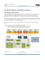
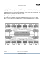
Sun SPARC Enterprise Architecture Overview...............................................................................138
The Jupiter Interconnect..............................................................................................................138
Functionality...........................................................................................................................140
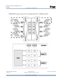
CPU and Memory Board Operational Overview....................................................................141
Technical Development Centre
Version 2.1
Page 3 of 327
Copyright © Sun Microsystems Ltd., 2008
Sun Proprietary and Confidential
Issue Date : August 2008
Sun Sparc Enterprise MX000 Servers
TDC008
Sun Proprietary and Confidential
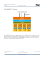
The SPARC64® VII Processor Differences for the Sun SPARC® Enterprise MX000 Servers
.................................................................................................................................................141
The SPARC64 VI Processor...................................................................................................142
The SPARC64 VII Processor..................................................................................................143
Supported Firmware and Software Versions..........................................................................144
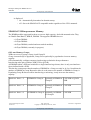
Limitations for the SPARC64 VII Processors .......................................................................144
The setdomainmode and showdomainmode Commands .......................................................144
SPARC64 VI Microprocessor Memory..................................................................................146
OPL uses Memory Groups. ...............................................................................................146
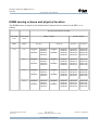
DIMM naming scheme and physical location..................................................................................148
Applicable memory population rules...............................................................................................149
Additional considerations.................................................................................................................152
Memory Mirroring..................................................................................................................154
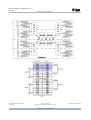
Memory Access Controller.....................................................................................................155
System Controller...................................................................................................................160
I/O Overview...........................................................................................................................161
Mid-Range Server IOU................................................................................................................161
High-End Server IOU..................................................................................................................162
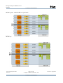
Board Nomenclature....................................................................................................................163
The Mid-Range Servers..........................................................................................................163
The High-End Servers.................................................................................................................166
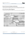
Service Processor Hardware Architecture........................................................................................168
Service Processor Block Diagram...............................................................................................168
Extended System Control Facility Functions...................................................................................172
Service Processor Functionality...................................................................................................172
Comparing Service Processors....................................................................................................173
M4000 and M5000 Servers.....................................................................................................173
M8000 and M9000 Servers.....................................................................................................174
Redundant Service Processors................................................................................................175
M9000+ Servers......................................................................................................................175
Service Processor Comparison Summary....................................................................................176
Service Processor Networks........................................................................................................177
DSCP Network........................................................................................................................177
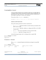
Network Configuration Settings..................................................................................................178
Commands Used.....................................................................................................................178
XSCF External and ISN Network................................................................................................179
Network Interfaces..................................................................................................................179
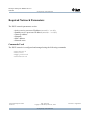
Required Network Parameters.....................................................................................................180
Commands Used.....................................................................................................................180
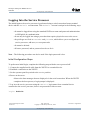
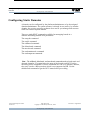
Configuring the Service Processor..............................................................................................181
Gathering Required Information.............................................................................................181
Logging Into the Service Processor.............................................................................................182
Technical Development Centre
Version 2.1
Page 4 of 327
Copyright © Sun Microsystems Ltd., 2008
Sun Proprietary and Confidential
Issue Date : August 2008
Sun Sparc Enterprise MX000 Servers
TDC008
Sun Proprietary and Confidential
Setting the Service Processor Time.............................................................................................184
Setting the Initial Date and Time............................................................................................185
Firmware Features and Functions................................................................................................186
XSCF Control Package...........................................................................................................186
Firmware Update Overview.........................................................................................................187
Firmware Update Features......................................................................................................188
Redundant Service Processors................................................................................................188
Enabling Escalation and Service Modes......................................................................................189
Mode Usage Overview............................................................................................................189
The enableservice Command.............................................................................................190
Options and Parameters......................................................................................................190
The service Command............................................................................................................191
Password Generation...............................................................................................................191
The enableescalation Command.............................................................................................192
The escalation Command.............................................................................................................192
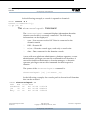
Operation of the Server ...................................................................................................................195
Display Server Hardware Environment.......................................................................................195
Commands Used to Display Information......................................................................195
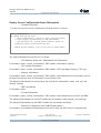
Displaying System Information..............................................................................................196
Display Server Configuration/Status Information..................................................................199
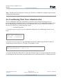
Air-Conditioning Wait Time Administration..............................................................................201
Warm-Up Time Administration..............................................................................................202
Shutdown Wait Time Administration.....................................................................................204
Identifying the Location of the System...................................................................................205
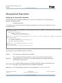
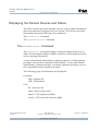
Managing Fault Degradation.......................................................................................................206
Displaying the Degraded Component.....................................................................................206
Switching the XSCF Unit.......................................................................................................207
Processing Continued at Failover..................................................................................207
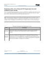
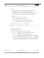
Displaying State of an External I/O Expansion Unit and Administration ioxadm .....................208
Displaying a List of External I/O Expansion Units, I/O Boards, Link Cards, and PSUs
or Displaying Their Environment Information..............................................................211
Displaying and Setting the Locator LED State of Each Specified Component in an
External I/O Expansion Unit.........................................................................................212
Turning On or Off Power to an I/O Board or PSU........................................................212
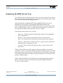
Exploring Domains...........................................................................................................................214
Domain Configuration.................................................................................................................215
Domain Configuration Unit (DCU)........................................................................................216
The M5000 Server..................................................................................................................218
The M8000 Server..................................................................................................................220
The M9000 and M9000+ Servers...........................................................................................222
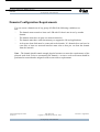
Domain Configuration Requirements..........................................................................................224
Configuring Static Domains........................................................................................................225
Technical Development Centre
Version 2.1
Page 5 of 327
Copyright © Sun Microsystems Ltd., 2008
Sun Proprietary and Confidential
Issue Date : August 2008
Sun Sparc Enterprise MX000 Servers
TDC008
Sun Proprietary and Confidential
The setupfru Command......................................................................................................226
The showfru Command......................................................................................................226
The setdcl Command..........................................................................................................227
The addboard Command....................................................................................................231
The showboards Command................................................................................................234
The deleteboard Command................................................................................................235
The moveboard Command.................................................................................................237
The setdomainmode Command..........................................................................................239
The setdomparam Command..............................................................................................242
Controlling Power to the Domain...........................................................................................243
Accessing the Domain Console..............................................................................................246
Resetting the Domain..............................................................................................................253
Exploring the OBP Device Tree..................................................................................................256
OPL DC Server............................................................................................................................259
OPL FF Server.............................................................................................................................261
CPU Decoding.............................................................................................................................263
Reminder :...............................................................................................................................263
Decoding the IDs :.......................................................................................................................263
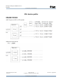
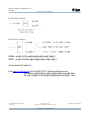
How to map the logical location to the physical location ?.........................................................269
Another example..........................................................................................................................270
IOU device paths..............................................................................................................................272
M4000/M5000.............................................................................................................................272
M8000/M9000.............................................................................................................................276
Device Mapping IO Expansion Box.................................................................................................280
Capacity on Demand .......................................................................................................................286
About Capacity on Demand.........................................................................................................286
COD Boards............................................................................................................................287
COD License Purchase...........................................................................................................287
License Installation.................................................................................................................288
License Allocation..................................................................................................................289
Headroom Management..........................................................................................................290
License Violations...................................................................................................................290
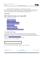
XSCF Shell Procedures for Using COD......................................................................................291
To Install a COD License .....................................................................................................291
To Delete a COD License ....................................................................................................292
To Reserve Licenses for Allocation .....................................................................................292
To Increase or Decrease Headroom .....................................................................................294
To Disable Headroom ..........................................................................................................295
To Display COD Information ..............................................................................................295
To Display COD License Status ..........................................................................................296
To Display Usage Statistics for COD Resources .................................................................297
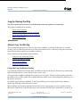
Log Archiving Facility ....................................................................................................................300
Technical Development Centre
Version 2.1
Page 6 of 327
Copyright © Sun Microsystems Ltd., 2008
Sun Proprietary and Confidential
Issue Date : August 2008
Sun Sparc Enterprise MX000 Servers
TDC008
Sun Proprietary and Confidential
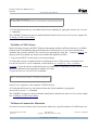
About Log Archiving...................................................................................................................300
Using the Log Archiving Facility...........................................................................................300
Archive Host Requirements....................................................................................................302
Log Archiving Errors .............................................................................................................302
Using the snapshot Tool..........................................................................................................302
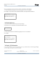
Solaris OS Procedures for Log Archiving...................................................................................302
To Configure the Log Archive Host ....................................................................................302
XSCF Shell Procedures for Log Archiving.................................................................................303
To Enable Log Archiving ....................................................................................................303
To Disable Log Archiving ...................................................................................................303
To Display Log Archiving Configuration and Status ..........................................................304
To Display Log Archiving Error Details .............................................................................304
Audit Configuration .........................................................................................................................306
About Auditing............................................................................................................................306
Audit Records.........................................................................................................................306
Audit Events............................................................................................................................307
Audit Classes...........................................................................................................................308
Audit Policy............................................................................................................................308
Audit File Tools......................................................................................................................308
XSCF Shell Procedures for Auditing...........................................................................................308
To Enable or Disable Writing of Audit Records to the Audit Trail .....................................309
To Configure an Auditing Policy .........................................................................................309
To Display Whether Auditing is Enabled Or Disabled ........................................................309
To Display Current Auditing Policy, Classes, or Events .....................................................310
Command Listing.............................................................................................................................313
Technical Development Centre
Version 2.1
Page 7 of 327
Copyright © Sun Microsystems Ltd., 2008
Sun Proprietary and Confidential
Issue Date : August 2008
Sun Sparc Enterprise MX000 Servers
TDC008
Sun Proprietary and Confidential
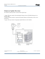
Overview
Technical Development Centre
Version 2.1
Page 8 of 327
Copyright © Sun Microsystems Ltd., 2008
Sun Proprietary and Confidential
Issue Date : August 2008
Sun Sparc Enterprise MX000 Servers
TDC008
Sun Proprietary and Confidential
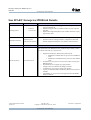
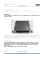
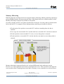
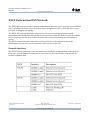
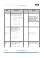
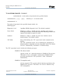
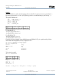
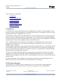
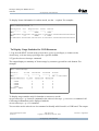
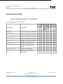
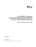
General Overview
Product
Internal Name
M4000
FF1
M5000
FF2
M8000
DC1
M9000
DC2/DC3
XCP 1072
XCP 1072
Technical Development Centre
Version 2.1
Page 9 of 327
Copyright © Sun Microsystems Ltd., 2008
Sun Proprietary and Confidential
Issue Date : August 2008
Sun Sparc Enterprise MX000 Servers
TDC008
Sun Proprietary and Confidential
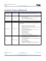
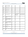
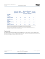
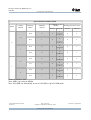
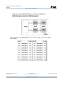
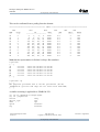
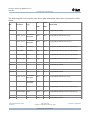
Facts at a Glance:
M4000
Processor
M5000
SPARC64 VI/VII
2.15GHz, 2.4GHz, 5MB L2$
Memory
Max 4 (8/16 core)
Max 8 (16/32 core)
Max 128GB
Max 256GB
32 DIMM slots
64 DIMM slots
(ECC, Chip-kill, Mirror) (ECC, Chip-kill, Mirror)
Internal Disks
Max 2 (2.5" SAS)
Removable Media
I/O Unit (IOU)
Interfaces
Default/Max Number of IOU's
DVD, DAT
2 x 10/100/1000 Mb HDX/FDX Ethernet ports
4 x 8 lane PCIe slots
1 x 133Mhz PCI-X Slot
One/One
One/Two
External IO Expansion
Default/Max of Internal HD's
Enclosure
Max 4 (2.5" SAS)
Yes
2/2 x 73 GB
2/4 x 73 GB
6U
10U
Redundant Parts
Disk, PSU, Fan
Hot-swappable parts
Disk, PSU, Fan
Power Options
Domains
RAS Management
1-phase 1+1 cables
1-phase 2+2 cables
Max 2
Max 4
XSCF (service processor)
Power
2350W
4700W
BTU/hr
8,018
16,036
Technical Development Centre
Version 2.1
Page 10 of 327
Copyright © Sun Microsystems Ltd., 2008
Sun Proprietary and Confidential
Issue Date : August 2008
Sun Sparc Enterprise MX000 Servers
TDC008
Sun Proprietary and Confidential
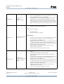
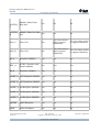
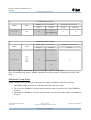
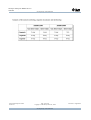
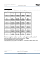
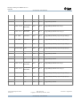
M8000
Processor
M9000
M9000-64
SPARC64 VI/VII
2.28GHz, 5MB L2$ or 2.4GHz, 6MB L2$, or 2.52GHz, 6MB L2$
Max 16 (32/64 core)
Memory
Internal Disks
Max 32 (64/128 core) Max 64 (128/256 core)
Max 512GB
Max 1TB
Max 2TB
128 DIMM slots
256 DIMM slots
512 DIMM slots
(ECC, Chip-kill,
Mirror)
(ECC, Chip-kill,
Mirror)
(ECC, Chip-kill,
Mirror)
Max 16 (2.5" SAS)
Max 32 (2.5" SAS)
Max 64 (2.5" SAS)
Removable Media
DVD, DAT
CMU (System Board)
Max 4 each
Max 8 each
Max 16 each
# of I/O Units (IOU)
Note: CMU reqd in
corresponding slot
1-4
1-8
1-16
# of 8 Lane PCIe Slots
per IOU
Max # of PCIe Slots
8
32
64
External IO Expansion
128
Yes
Redundant Parts
CMU, IOU, XSCF,
Disk, PSU, Fan
CMU, IOU, XSCF, Clock board, Disk, PSU,
Fan, XBU
Hot-Swappable Parts
CMU, IOU, XSCF,
CMU, IOU, XSCF, XBU*,
Disk, PSU, Fan
CLKU*, Disk, PSU, Fan
Power Options
Max Power
1-phase/3-phase/dual-grid
10,500 [W]
21,300 [W]
42,600 [W]
11,000 [VA]
22,400 [VA]
44,800 [VA]
BTU/hr
35,834
72,693
145,385
Domains
Max 16
Max 24
RAS Management
2 x XSCF (service processor)
* CLKU and XBU hot-swap will be a post-RR feature.
Technical Development Centre
Version 2.1
Page 11 of 327
Copyright © Sun Microsystems Ltd., 2008
Sun Proprietary and Confidential
Issue Date : August 2008
Sun Sparc Enterprise MX000 Servers
TDC008
Sun Proprietary and Confidential
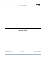
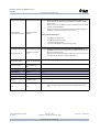
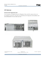
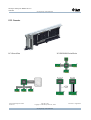
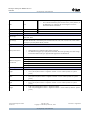
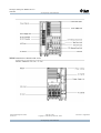
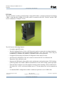
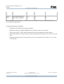
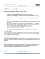
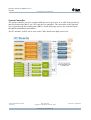
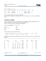
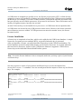
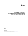
M4000/M5000 Product Overview
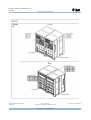
Both midrange servers are based on the SPARC64 VI/VII processors.
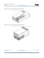
M4000 Front View
M4000 Rear View
Technical Development Centre
Version 2.1
Page 12 of 327
Copyright © Sun Microsystems Ltd., 2008
Sun Proprietary and Confidential
Issue Date : August 2008
Sun Sparc Enterprise MX000 Servers
TDC008
Sun Proprietary and Confidential
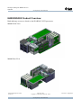
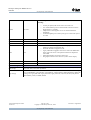
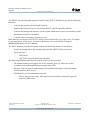
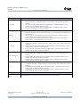
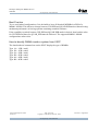
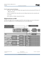
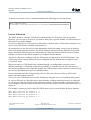
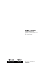
M5000 Front View
M5000 Rear View
Technical Development Centre
Version 2.1
Page 13 of 327
Copyright © Sun Microsystems Ltd., 2008
Sun Proprietary and Confidential
Issue Date : August 2008
Sun Sparc Enterprise MX000 Servers
TDC008
Sun Proprietary and Confidential
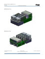
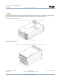
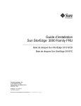
Front view of the SPARC Enterprise SPARC Enterprise M4000 and M5000 servers.
Technical Development Centre
Version 2.1
Page 14 of 327
Copyright © Sun Microsystems Ltd., 2008
Sun Proprietary and Confidential
Issue Date : August 2008
Sun Sparc Enterprise MX000 Servers
TDC008
Sun Proprietary and Confidential
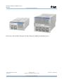
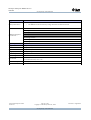
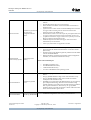
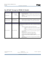
Sun SPARC Enterprise M4000 Details:
Software
Details
•
Operating System
Additional Software
Notes
Solaris 10
(11/06)
Pre-installed Software
•
Solaris 10 is pre-installed on all server configurations.
•
Java Enterprise System is preloaded at the factory and available for
immediate deployment.
The Java Enterprise system pre-load does not entitle commercial
use, it is for evalutation purposes only.
Ships with a 90-day evaluation and is feature-complete.
•
•
Hardware
Details
Notes
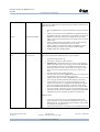
The M4000 motherboard has (2) available CPU module connectors to install
"CPU Modules". (2 or 4) processors can be installed into the M4000 via (1 or
2) "CPU Modules".
•
•
•
Processors (CPU's)
Up to 4 Processors
•
•
•
•
•
•
•
•
•
•
Memory
Maximum of 128GB
Technical Development Centre
Version 2.1
•
•
•
•
•
Supports SPARC64 VI Dual-Core CPU Modules
SPARC64 VI CPU Modules include: 2.15GHz
System memory is not located on the CPU modules, it is located on
separate memory modules.
Each SPARC64 VI (Olympus-C) processor contains two cores.
Each core supports two CMT strands.
Each core has its own L1 cache:
L1 D-cache 128 Kbytes
L1 I-cache 128 Kbytes
Both cores share the L2 cache.
L2 cache 5 Mbytes (10-way interleave)
Capacity on Demand (COD) configurations are available.
Memory DIMM slots are located on Memory modules.
The M4000 motherboard has (4) memory module connectors to
connect memory modules.
A max of (4) memory modules can be installed in a M4000 server.
A memory module:
Contains (8) DIMM slots
Holds 1, 2 and 4GB DIMM's
The M4000 provides extended ECC memory protection (chip offlining) and mirroring, end-to end ECC memory protection.
Page 15 of 327
Copyright © Sun Microsystems Ltd., 2008
Sun Proprietary and Confidential
Issue Date : August 2008
Sun Sparc Enterprise MX000 Servers
TDC008
Sun Proprietary and Confidential
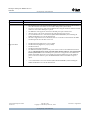
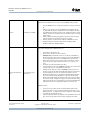
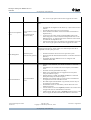
Power Supplies
Includes 2 power
supplies
Includes 2 fan trays
•
•
•
•
The M4000 comes with N+1 Redundant Power Supplies (2 total).
A fully configured M4000 server can operate with (1) power supply.
Power supplies and fan trays are hot swappable
Standard power cords are included with the M4000 server and are
designed to connect the the Sun Rack 1000 MPS power option.
Therefore no power cords need to be specified for the Sun SPARC
Enterprise M4000 server used with the Sun Racks. However, option
power cords can be specified for use with alternate power sources.
•
•
The M4000 requires (1) I/O Unit to be installed in the system.
The Internal I/O Unit is Hot-Pluggable.
The I/O Unit can accomodate :
•
•
(4) X8 PCI-E slots
(1) 64-bit PCI-X slot @ 133MHz
Additional Notes:
Internal I/O Unit
(1) I/O Unit configured
with each server.
•
•
•
•
•
•
•
•
•
External I/O Unit
Maximum of (2)
External I/O Units can be
configured within the
system.
•
•
•
•
Technical Development Centre
Version 2.1
(1) PCI-E slot in an IOU will be needed for each Optical Link Card
or Copper Link Card being used to connect the External I/O
Expansion Units to the M4000 server.
Each I/O Boat contains a seventh slot for the first Optical Link Card
or Copper Link Card connection to the internal IOU in the server.
(1) Optical Link Card or Copper Link Card is required for each I/O
Boat of an External I/O Expansion Unit.
Additional Optical Link Cards and Copper Link Cards can be
installed in any slot in the IOU.
A max of (4) Link Cards are supported in an IOU.
Each External I/O Expansion Unit houses (1 or 2) PCI-E or PCI-X I/
O Boats.
Each I/O Boat has (6) PCI-E or (6) PCI-X slots.
PCI-E and PCI-X I/O Boats can be mixed within an External I/O
Expansion Unit..
(1) PCI-E slot in an IOU will be needed for each Optical Link Card
or Copper Link Card being used to connect the External I/O
Expansion Units to the M4000 server.
Each I/O Boat contains a seventh slot for the first Optical Link Card
or Copper Link Card connection to the internal IOU in the server.
(1) Optical Link Card or Copper Link Card is required for each I/O
Boat of an External I/O Expansion Unit.
Additional Optical Link Cards and Copper Link Cards can be
installed in any slot in the IOU.
A max of (4) Link Cards are supported in an IOU.
Page 16 of 327
Copyright © Sun Microsystems Ltd., 2008
Sun Proprietary and Confidential
Issue Date : August 2008
Sun Sparc Enterprise MX000 Servers
TDC008
Sun Proprietary and Confidential
•
•
•
•
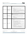
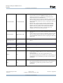
Extended System
Monitoring/Control
Control Facility (XCSF) Faclility
XSCF Unit Technical Specs:
Internal Disk Drives
Maximum of (2) SAS
drives.
Internal DVD-ROM
Includes (1) DVD-ROM.
Internal Tape Drive
Optional DAT Tape
Drive.
Internal Floppy Drive
None
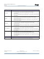
External Ports
Details
SCSI
None
Fibre Channel
None
Ethernet
(2) Ethernet ports
Serial
None
Technical Development Centre
Version 2.1
The XSCF firmware runs on the service processor system.
The board with the installed XCSF firmware is called the XSCFU
(XSCF Unit).
The XSCF Unit for the M4000 is physically different than the XSCF
Unit for the M8000/M9000.
Manages hardware configuration and health, domain configuration
and status, error monitor and notification facility.
•
•
•
•
533-MHz PowerQICC CPU.
512-MB DRAM main memory.
1-GB NAND Flash memory.
A version of Embedded Linux operating system.
•
•
Up to (2) hot-plugable 73GB 10K RMP 2.5" SAS Disk Drives.
146GB drives are currently supported in the M4000 but they are not
part of any standard config,
thus drives from standard configs (73GB) would have to be removed
and replaced with the with x-option 146GB drives.
•
All M4000 configurations come with (1) DVD-ROM drive.
•
Up to (1) DAT Tape Drive can be installed in the M4000.
Notes
•
(2) integrated 1-Gbit Ethernet ports.
•
Legacy SAI/P PCI Adapters can be used in the M4000 PCI-X slot
on the I/O Unit or in the optional External I/O Expansion Unit at
GA.
Page 17 of 327
Copyright © Sun Microsystems Ltd., 2008
Sun Proprietary and Confidential
Issue Date : August 2008
Sun Sparc Enterprise MX000 Servers
TDC008
Sun Proprietary and Confidential
The XSCFU provides several external interfaces for communication
including:
•
•
XCSFU
See Notes.
•
•
Parallel
None
USB
None
Keyboard
None
•
•
•
Video
None
•
•
A serial port (RJ-45) that can be used to access the CLI.
Two 10/100 Ethernet ports on which both the CLI and a browserbased interface is available.
USB port that a field engineer can use to download hardware
information.
An uninterruptible power control (UPC) port to connect the system
to a UPS.
The XVR-200 and the Legacy 2D XVR-100 graphics card may be
installed for display/visualization only.
The XVR-200 will be supported at GA.
Legacy 2D XVR-100 graphics card can be used in the M4000 PCIX slot on the I/O Unit or in the optional External I/O Expansion
Unit at RR.
XVR-300x8 graphics accelerator, 24-bit color.
The graphics card can not be used as a system console display.
Audio
None
Other
None
External Storage
Details
Disk Storage
D240, FLX280, ST2540, 3120, 3320, 3510FC, 3511, 5320 NAS, 6140, 6540, FLX380, 9910, 9960,
9970, 9980, 9985, 9990, EMC Symmetrix
Tape Storage
DAT 72 Rackmount, LTO3 Rackmount, LTO2V Rackmount, SDLT600 Rackmount, DAT 72 Desktop,
DAT 72 USB Desktop, LTO3 Desktop, LTO2 Desktop, LTO2V Desktop, SDLT600 Desktop, SDLT320
Desktop, C2, Legacy STK L20, Legacy STK L40, Legacy STK L80, C4, L180, SL500 (LTO), SL500
(Mixed Media), L700e, L1400M, SL8500
Technical Development Centre
Version 2.1
Page 18 of 327
Copyright © Sun Microsystems Ltd., 2008
Sun Proprietary and Confidential
Issue Date : August 2008
Sun Sparc Enterprise MX000 Servers
TDC008
Sun Proprietary and Confidential
Supported Boot Devices Details
•
•
Primary Boot Device
The (2) internal disks in the M4000.
The M4000 can not boot from any storage attached to an External I/O Unit.
Sun StorageTek 2540
Additional Supported
Boot Devices
Sun StorageTek 6140
Sun Storage 3120
Sun StorEdge 3510FC
Sun StorEdge 9980
Sun StorEdge 9985
Physical Specs
Details
Height
10.3" (263 mm)
Width
17.5" (444.5 mm)
Depth
32.7" (831 mm)
Weight (max)
185 lbs (83.9 kg)
Electrical Specs
Details
Input Voltage
100-240 VAC, 47-63Hz
Input Current
24.0A at 100 127 VAC, 12A / cord
12.0A at 200 240 VAC, 12A / cord
Power Consumption
2,350W (Max)
BTU's
8,018 BTU/hr max
Technical Development Centre
Version 2.1
Page 19 of 327
Copyright © Sun Microsystems Ltd., 2008
Sun Proprietary and Confidential
Issue Date : August 2008
Sun Sparc Enterprise MX000 Servers
TDC008
Sun Proprietary and Confidential
Rack Info
Details
Rack Units
6RU enclosure.
•
•
•
•
•
•
Supported Racks
Technical Development Centre
Version 2.1
The standard power cords included with the M4000 are designed to connect to the Sun Rack
1000-42 with either 60A 3-Phase or 32A 3-Phase MPS power systems ONLY.
No power cords need to be ordered for the M4000 when using the Sun Rack 1000-42 with 60A
3-Phase or 32A 3-Phase MPS power systems.
The M4000 is NOT supported connected to the PDS power option in Sun racks.
Alternate power cords can be specified for use with alternate power sources.
It is recommended to use a rack extension (XRACK-EXTEND38RU) when installing the
M4000 and M5000 servers into the Rack 900-38.
900-36N is supported but not recommended, there is no extender for 900-36N thus the M4K
and M5K protrude from the back of the rack.
•
•
•
•
•
Sun Rack 900-36N (Support may vary by GEM)
Sun Rack 900-38 (Support may vary by GEM)
Sun Rack 1000-38
Sun Rack 1000-42 (Recommended)
The M4000 and M5000 systems include power cords to connect to the MPS inside the Rack
900-38. The included power cords work with either the 60A 3-Phase or 32A 3-Phase MPS
Power Systems ONLY. The rack PDS power systems are not supported for the M4000 and
M5000. If the MPS options are not acceptable, then optional NEMA (US) or IEC (EMEA)
power cords can be ordered to power the M4000/M5000 outside of the MPS rack power
option.
•
It is recommended to use a rack extention (XRACK-EXTEND38RU) when installing the
M4000 and M5000 servers into the Rack 900-38.
Page 20 of 327
Copyright © Sun Microsystems Ltd., 2008
Sun Proprietary and Confidential
Issue Date : August 2008
Sun Sparc Enterprise MX000 Servers
TDC008
Sun Proprietary and Confidential
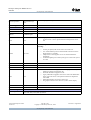
Sun SPARC Enterprise M5000 Details:
Software
Details
•
Operating System
Notes
Solaris 10
(11/06)
Additional Software
Pre-installed Software
Hardware
Details
•
Solaris 10 is pre-installed on all server configurations.
•
Java Enterprise System is preloaded at the factory and available for
immediate deployment.
• The Java Enterprise system pre-load does not entitle
commercial use, it is for evalutation purposes only.
• Ships with a 90-day evaluation and is feature-complete.
Notes
The M5000 motherboard has (4) available CPU module connectors to install
"CPU Modules". (2, 4, 6 or 8) processors can be installed into the M5000 via
(1, 2, 3 or 4) "CPU Modules".
•
•
Processors (CPU's)
Up to 8 Processors
•
•
•
•
•
•
•
Memory
Maximum of 256GB
•
•
•
Technical Development Centre
Version 2.1
Supports SPARC64 VI Dual-Core CPU Modules
• SPARC64 VI CPU Modules include: 2.15GHz
System memory is not located on the CPU modules, it is located on
separate memory modules.
Each SPARC64 VI (Olympus-C) processor contains two cores.
Each core supports two CMT strands.
Each core has its own L1 cache:
• L1 D-cache 128 Kbytes
• L1 I-cache 128 Kbytes
Both cores share the L2 cache.
• L2 cache 5 Mbytes (10-way interleave)
Capacity on Demand (COD) configurations are available.
Memory DIMM slots are located on Memory modules.
The M5000 motherboard has (8) memory module connectors to
connect memory modules.
A max of (8) memory modules can be installed in a M5000 server.
A memory module:
• Contains (8) DIMM slots
• Holds 1, 2 and 4GB DIMM's
The M5000 provides extended ECC memory protection (chip offlining) and mirroring, end-to end ECC memory protection.
Page 21 of 327
Copyright © Sun Microsystems Ltd., 2008
Sun Proprietary and Confidential
Issue Date : August 2008
Sun Sparc Enterprise MX000 Servers
TDC008
Sun Proprietary and Confidential
Power Supplies
•
•
•
•
Includes 4 power
supplies
Includes 4 fan trays
The M5000 comes with 2+2 Redundant Power Supplies (4 total).
Second and fourth supplies are redundant.
Power supplies and fan trays are hot swappable
Standard power cords are included with the M5000 server and are
designed to connect the the Sun Rack 1000 MPS power option.
Therefore no power cords need to be specified for the Sun SPARC
Enterprise M5000 server used with the Sun Racks. However, option
power cords can be specified for use with alternate power sources.
Each I/O Units contains:
•
•
•
•
(4) X8 PCI-E slots
(1) 64-bit PCI-X slot @ 133MHz
(2) SAS disk bays
(2) Gigabit Ethernet ports
I/O Unit Notes:
•
•
•
•
Internal I/O Unit
Up to (2) I/O Units can
be configured with each
server.
The M5000 requires (1) I/O Unit to be installed in the system.
The Internal I/O Unit is Hot-Pluggable.
The servers come with PCI cassettes for the I/O Units.
To use an IO tray, each system board must have a minimum of (1)
CPUM board and (1) MEM board.
• For example: When using (2) I/O trays, it is required to
have (2) cpu module boards and (2) memory boards.
Additional Notes regarding the external I/O units:
•
•
•
•
•
Technical Development Centre
Version 2.1
(1) PCI-E slot in an IOU will be needed for each Optical Link Card
or Copper Link Card being used to connect the External I/O
Expansion Units to the M5000 server.
Each I/O Boat contains a seventh slot for the first Optical Link Card
or Copper Link Card connection to the internal IOU in the server.
(1) Optical Link Card or Copper Link Card is required for each I/O
Boat of an External I/O Expansion Unit.
Additional Optical Link Cards and Copper Link Cards can be
installed in any slot in the IOU.
A max of (4) Link Cards are supported in an IOU.
Page 22 of 327
Copyright © Sun Microsystems Ltd., 2008
Sun Proprietary and Confidential
Issue Date : August 2008
Sun Sparc Enterprise MX000 Servers
TDC008
Sun Proprietary and Confidential
•
•
•
•
External I/O Units
Maximum of (4) external
I/O Units can be
configured within the
system.
•
•
•
•
•
•
•
•
Extended System
Monitoring/Control
Control Facility (XCSF) Faclility
The XSCF firmware runs on the service processor system.
The board with the installed XCSF firmware is called the XSCFU
(XSCF Unit).
The XSCF Unit for the M5000 is physically different than the XSCF
Unit for the M8000/M9000.
Manages hardware configuration and health, domain configuration
and status, error monitor and notification facility.
XSCF Unit Technical Specs:
•
•
•
•
533-MHz PowerQICC CPU.
512-MB DRAM main memory.
1-GB NAND Flash memory.
A version of Embedded Linux operating system.
•
•
Up to (4) hot-plugable 73GB or 146GB 10K RMP 2.5" SAS Disk
Drives.
The qty (2) HDD standard configs comes with 73GB drives only.
The qty (4) HDD standard config comes with the second IOU
already and with 73GB drives only.
146GB drives are supported in the M5000 but they are not currently
part of any standard configs, thus drives from standard configs
(73GB) would have to be removed in the field and replaced with the
with x-option 146GB drives. Alternatively, for qty (2) HDD
standard configs, an optional second IOU could be added and could
house 73GB or 146GB x-option drives.
•
All M5000 configurations come with (1) DVD-ROM drive.
•
•
Internal Disk Drives
Maximum of (4) SAS
drives.
Internal DVD-ROM
Includes (1) DVD-ROM.
Technical Development Centre
Version 2.1
Each External I/O Expansion Unit houses (1 or 2) PCI-E or PCI-X I/
O Boats.
Each I/O Boat has (6) PCI-E or (6) PCI-X slots.
PCI-E and PCI-X I/O Boats can be mixed within an External I/O
Expansion Unit.
(1) PCI-E slot in an IOU will be needed for each Optical Link Card
or Copper Link Card being used to connect the External I/O
Expansion Units to the M5000 server.
Each I/O Boat contains a seventh slot for the first Optical Link Card
or Copper Link Card connection to the internal IOU in the server.
(1) Optical Link Card or Copper Link Card is required for each I/O
Boat of an External I/O Expansion Unit.
Additional Optical Link Cards and Copper Link Cards can be
installed in any slot in the IOU.
A max of (4) Link Cards are supported in an IOU.
Page 23 of 327
Copyright © Sun Microsystems Ltd., 2008
Sun Proprietary and Confidential
Issue Date : August 2008
Sun Sparc Enterprise MX000 Servers
TDC008
Sun Proprietary and Confidential
Internal Tape Drive
Optional DAT Tape
Drive.
Internal Floppy Drive
None
External Ports
Details
SCSI
None
Fibre Channel
None
Ethernet
(4) Ethernet ports
Serial
•
Up to (1) DAT Tape Drive can be installed in the M5000.
Notes
•
(4) integrated 1-Gbit Ethernet ports.
•
Legacy SAI/P PCI Adapters can be used in the M5000 PCI-X slot
on the I/O Unit or in the optional External I/O Expansion Unit at
GA.
None
The XSCFU provides several external interfaces for communication
including:
•
•
XCSFU
See Notes.
•
•
Parallel
None
USB
None
Keyboard
None
•
•
•
Video
None
•
•
A serial port (RJ-45) that can be used to access the CLI.
Two 10/100 Ethernet ports on which both the CLI and a browserbased interface is available.
USB port that a field engineer can use to download hardware
information.
An uninterruptible power control (UPC) port to connect the system
to a UPS.
The XVR-200 and the Legacy 2D XVR-100 graphics card may be
installed for display/visualization only.
The XVR-200 will be supported at GA.
Legacy 2D XVR-100 graphics card can be used in the M5000 PCIX slot on the I/O Unit or in the optional External I/O Expansion
Unit at RR.
XVR-300x8 graphics accelerator, 24-bit color.
The graphics card can not be used as a system console display.
Audio
None
Other
None
External Storage
Details
Disk Storage
D240, FLX280, ST2540, 3120, 3320, 3510FC, 3511, 5320 NAS, 6140, 6540, FLX380, 9910, 9960,
9970, 9980, 9985, 9990, EMC Symmetrix
Technical Development Centre
Version 2.1
Page 24 of 327
Copyright © Sun Microsystems Ltd., 2008
Sun Proprietary and Confidential
Issue Date : August 2008
Sun Sparc Enterprise MX000 Servers
TDC008
Sun Proprietary and Confidential
Tape Storage
DAT 72 Rackmount, LTO3 Rackmount, LTO2V Rackmount, SDLT600 Rackmount, DAT 72 Desktop,
DAT 72 USB Desktop, LTO3 Desktop, LTO2 Desktop, LTO2V Desktop, SDLT600 Desktop, SDLT320
Desktop, C2, Legacy STK L20, Legacy STK L40, Legacy STK L80, C4, L180, SL500 (LTO), SL500
(Mixed Media), L700e, L1400M, SL8500
Supported Boot Devices Details
•
•
Primary Boot Device
The (4) internal disks in the M5000.
The M5000 can not boot from any storage attached to an External I/O Unit.
Sun StorageTek 2540
Sun StorageTek 6140
Additional Supported
Boot Devices
Sun Storage 3120
Sun StorEdge 3510FC
Sun StorEdge 9980
Sun StorEdge 9985
Physical Specs
Details
Height
17.3" (440 mm)
Width
17.5" (444.5 mm)
Depth
32.1" (816 mm)
Weight (max)
275 lbs (124.7 kg)
Electrical Specs
Details
Input Voltage
100-240 VAC, 47-63Hz
Input Current
48A at 100-127 VAC (12A per cord)
24A at 200-240 VAC (12A per cord 2+2 redundancy)
Power Consumption
4,590W (Max)
BTU's
15,661 BTU/hr max
Rack Info
Details
Rack Units
10RU enclosure.
•
•
•
•
•
Supported Racks
•
•
•
•
•
Technical Development Centre
Version 2.1
The standard power cords included with the M5000 are designed to connect to the Sun Rack
1000-42 with either 60A 3-Phase or 32A 3-Phase MPS power systems ONLY.
No power cords need to be ordered for the M5000 when using the Sun Rack 1000-42 with 60A
3-Phase or 32A 3-Phase MPS power systems.
The M5000 is NOT supported connected to the PDS power option in Sun racks.
Alternate power cords can be specified for use with alternate power sources.
It is recommended to use a rack extention (XRACK-EXTEND38RU) when installing the
M4000 and M5000 servers into the Rack 900-38
900-36N is supported but not recommended, there is no extender for 900-36N thus the M4K
and M5K protrude from the back of the rack.
Sun Rack 900-36N (Support may vary by GEM)
Sun Rack 900-38 (Support may vary by GEM)
Sun Rack 1000-38
Sun Rack 1000-42 (Recommended)
Page 25 of 327
Copyright © Sun Microsystems Ltd., 2008
Sun Proprietary and Confidential
Issue Date : August 2008
Sun Sparc Enterprise MX000 Servers
TDC008
Sun Proprietary and Confidential
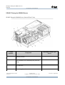
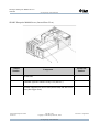
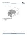
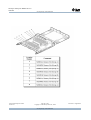
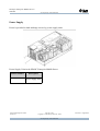
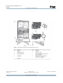
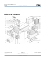
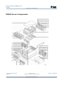
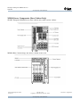
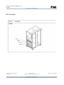
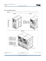
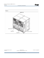
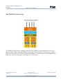
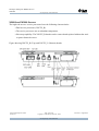
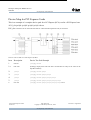
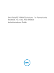
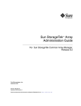
SPARC Enterprise M4000 Server
SPARC Enterprise M4000 Server (Internal Front View)
Callout
Number
Maximum Number per
Server
Component
1
Memory boards
4
2
CPU modules each containing two processor
chips
2
3
172 mm fans
2
4
Power supply units
2
Technical Development Centre
Version 2.1
Page 26 of 327
Copyright © Sun Microsystems Ltd., 2008
Sun Proprietary and Confidential
Issue Date : August 2008
Sun Sparc Enterprise MX000 Servers
TDC008
Sun Proprietary and Confidential
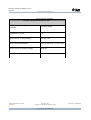
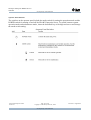
Callout
Number
Maximum Number per
Server
Component
5
Hard disk drives, Serial-attached SCSI
2
6
DVD drive
1
7
Tape drive unit (DAT), optional
1
Technical Development Centre
Version 2.1
Page 27 of 327
Copyright © Sun Microsystems Ltd., 2008
Sun Proprietary and Confidential
Issue Date : August 2008
Sun Sparc Enterprise MX000 Servers
TDC008
Sun Proprietary and Confidential
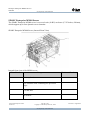
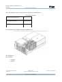
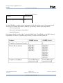
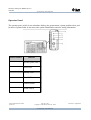
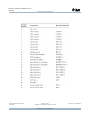
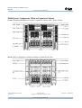
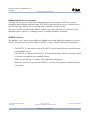
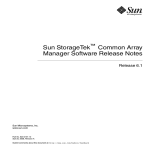
SPARC Enterprise M4000 Server (Internal Rear View)
Callout
Number
Maximum
Number
Component
1
60 mm fans
2
2
eXtended System Control Facility Unit (XSCFU)
1
3
I/O unit--supports one PCI-X slot (lowest slot) and four PCIe
1
slots (four upper slots)
Technical Development Centre
Version 2.1
Page 28 of 327
Copyright © Sun Microsystems Ltd., 2008
Sun Proprietary and Confidential
Issue Date : August 2008
Sun Sparc Enterprise MX000 Servers
TDC008
Sun Proprietary and Confidential
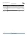
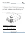
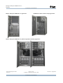
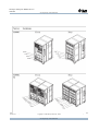
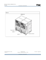
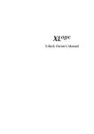
SPARC Enterprise M5000 Server
The SPARC Enterprise M5000 server is a ten-rack unit (10 RU) enclosure (17.25 inches, 438 mm),
which supports up to four dynamic server domains.
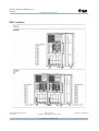
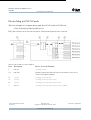
SPARC Enterprise M5000 Server (Internal Front View)
Internal front view of the M5000 server.
Callout Number
Component
Maximum Number
1
Memory boards
8
2
CPU modules each containing two processor
chips
4
3
172 mm fans
4
4
DVD drive
1
Technical Development Centre
Version 2.1
Page 29 of 327
Copyright © Sun Microsystems Ltd., 2008
Sun Proprietary and Confidential
Issue Date : August 2008
Sun Sparc Enterprise MX000 Servers
TDC008
Sun Proprietary and Confidential
Callout Number
Component
Maximum Number
5
Power supply units
4
6
Tape drive unit (DAT), optional
1
7
Hard disk drives, Serial-attached SCSI (SAS)
4
Technical Development Centre
Version 2.1
Page 30 of 327
Copyright © Sun Microsystems Ltd., 2008
Sun Proprietary and Confidential
Issue Date : August 2008
Sun Sparc Enterprise MX000 Servers
TDC008
Sun Proprietary and Confidential
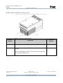
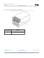
SPARC Enterprise M5000 Server (Rear View)
Rear view of the SPARC Enterprise M5000 server
Callout
Number
1
Maximum
Number
Component
eXtended System Control Facility Unit (XSCFU)
1
I/O unit
2
Each I/O unit supports one PCI-X slot (lowest slot) and four
PCIe slots (four upper slots)
Technical Development Centre
Version 2.1
Page 31 of 327
Copyright © Sun Microsystems Ltd., 2008
Sun Proprietary and Confidential
2
Issue Date : August 2008
Sun Sparc Enterprise MX000 Servers
TDC008
Sun Proprietary and Confidential
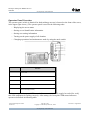
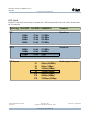
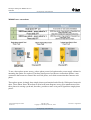
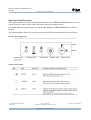
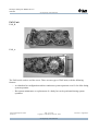
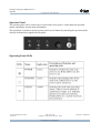
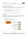
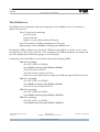
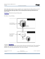
Operator Panel Overview
The operator panel, which is identical for both midrange servers is located on the front of the server,
in the upper right corner () The operator panel is used for the following tasks:
•
Displaying the server status
•
Storing server identification information
•
Storing user setting information
•
Turning on the power supply of all domains
•
Changing operational and maintenance mode by using the mode switch
Function
1
Power LED
2
XSCF STANDBY LED
3
Check LED
4
POWER button
5
Mode switch (keyswitch)
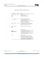
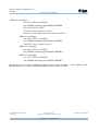
During startup, the front panel LED status indicators are individually toggled on and off to verify
that each component is working correctly. After startup, the front panel LED status indicators
operate as described in following table.
Technical Development Centre
Version 2.1
Page 32 of 327
Copyright © Sun Microsystems Ltd., 2008
Sun Proprietary and Confidential
Issue Date : August 2008
Sun Sparc Enterprise MX000 Servers
TDC008
Sun Proprietary and Confidential
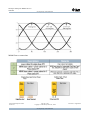
Operator Panel LEDs and MODE Switch
Technical Development Centre
Version 2.1
Page 33 of 327
Copyright © Sun Microsystems Ltd., 2008
Sun Proprietary and Confidential
Issue Date : August 2008
Sun Sparc Enterprise MX000 Servers
TDC008
Sun Proprietary and Confidential
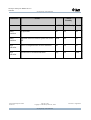
The combination of the LED status indicators show server status.
Status Indicator LED Pattern Summary
Indication
Status
XSCF
Standby
POWER XSCF Ready Check
Status
transition
External circuit breaker off
Off
Off
Off
Status
transition
External circuit breaker on
Off
Off
On
Status
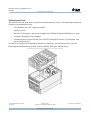
transition
XSCF initialization
Off
Blink
Off
Status
transition
Error detection by the XSCF self check
Off
Off
On
Status
transition
Standby (waiting for the operator to power
the server on)
Off
On
Off
Status
transition
Waiting for air conditioner power on
Off
On
Off
Status
transition
Warm up (in case that delayed power on
configured)
On
On
Off
Status
transition
Power on sequential process (each domain
starts the operation)
On
On
Off
Technical Development Centre
Version 2.1
Page 34 of 327
Copyright © Sun Microsystems Ltd., 2008
Sun Proprietary and Confidential
Issue Date : August 2008
Sun Sparc Enterprise MX000 Servers
TDC008
Sun Proprietary and Confidential
Indication
Status
XSCF
Standby
POWER XSCF Ready Check
Status
transition
In operation
On
On
Off
Status
transition
Operator issued an order to power the server
off
Blink
On
Off
Fault
indication
Server is suspended due to error detection
Off
On
On
Fault
indication
Locator/server location indication
Any
On
Blink
Technical Development Centre
Version 2.1
Page 35 of 327
Copyright © Sun Microsystems Ltd., 2008
Sun Proprietary and Confidential
Issue Date : August 2008
Sun Sparc Enterprise MX000 Servers
TDC008
Sun Proprietary and Confidential
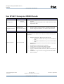
Components
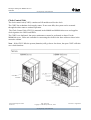
Components that are removed using "hot FRU removal" can be removed from the server and
replaced while the operating server is running without performing a dynamic reconfiguration
operation. Components that are removed using "active FRU removal" must be dynamically
reconfigured out of the domain before removing the component.
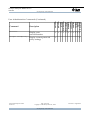
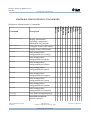
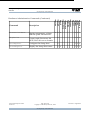
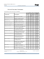
There are three basic methods for replacing FRUs from the MX000 servers, these are:
●
●
●
Hot-FRU replacement – Uses the XSCF replacefru command to power down the
component. Hot-FRU removal is used for components not used by the Solaris OS
domains.
Active-FRU replacement – Uses dynamic reconfiguration (DR) to remove an active
component. Active-FRU removal is used for components that are used by the Solaris OS
domain to avoid disrupting the domain during the removal and replacement procedures.
Cold-FRU replacement – Powers the system off and unplugs the power cables from the
input power source. Cold-FRU removal is used when the component cannot be safely
removed while the system is powered on
.
Note – The replacefru command along with Hot-FRU removal, and Active-FRU removal are
described in detail later in the course. In this module, you remove and install all components with
power turned off.
Technical Development Centre
Version 2.1
Page 36 of 327
Copyright © Sun Microsystems Ltd., 2008
Sun Proprietary and Confidential
Issue Date : August 2008
Sun Sparc Enterprise MX000 Servers
TDC008
Sun Proprietary and Confidential
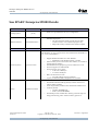
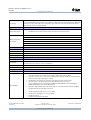
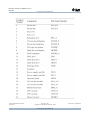
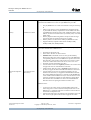
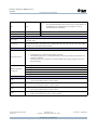
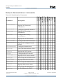
Sun SPARC Enterprise M4000/M5000
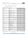
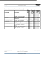
FRU
Description
Cold Hot
Active
MBU_A
Motherboard Unit (M4000)
Yes No
No
MBU_B
Motherboard Unit (M5000)
Yes No
No
DDC_A
DC-DC Converter (Motherboard
and IO Unit)
Yes No
No
DDC_B
DC-DC Converter with metal
Yes No
heatsink (Motherboard and IO Unit)
No
CMU_A
CPU Module Unit
Yes No
No
MEMB
Memory Board
Yes No
No
DIMM
Main Memory DIMM (1, 2, or
4GB)
Yes No
No
XSCFU
eXtended System Control Facility
Unit
Yes No
No
IOU
I/O Unit
Yes No
No
DDCR
I/O DC Riser
Yes No
No
PCIC
PCI Cassette (including PCI card)
Yes No
Yes
FAN_A
172mm Fans
Yes
FAN_B
60mm Fan (M4000)
Yes Yes, One unit at a time to No
Technical Development Centre
Version 2.1
Yes, One unit at a time to
No
support redundancy
Page 37 of 327
Copyright © Sun Microsystems Ltd., 2008
Sun Proprietary and Confidential
Issue Date : August 2008
Sun Sparc Enterprise MX000 Servers
TDC008
Sun Proprietary and Confidential
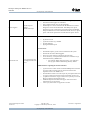
support redundancy
FANBP_
172mm Fan Backplane (M4000)
A
Yes No
No
FANBP_B 60mm Fan Backplane (M4000)
Yes No
No
FANBP_C 172mm Fan Backplane (M5000)
Yes No
No
PSU
Power Supply Unit
Yes
BPU_A
I/O Backplane / Power Backplane
(M4000)
Yes No
No
BPU_B
Bus Bar / I/O Backplane / Power
Backplane (M5000)
Yes No
No
HDD
73GB Hard Disk Drive
Yes No
Yes
HDDBP
Hard Disk Drive backplane
Yes No
No
TAPE
DAT Tape Drive (Optional)
Yes No
Yes
TAPEBP DAT Tape Drive Backplane
Yes No
No
DVD
Yes No
No
DVDBP_
DVD Drive Backplane (M4000)
A
Yes No
No
DVDBP_
DVD Drive Backplane (M5000)
B
Yes No
No
OPNL
Yes No
No
DVD Drive
Operator Panel
Technical Development Centre
Version 2.1
Yes, One unit at a time to
No
support redundancy
Page 38 of 327
Copyright © Sun Microsystems Ltd., 2008
Sun Proprietary and Confidential
Issue Date : August 2008
Sun Sparc Enterprise MX000 Servers
TDC008
Sun Proprietary and Confidential
The information in the table above comes from the Sun™ SPARC® Enterprise M4000/M5000
Servers Service Manual, Appendix C.
Technical Development Centre
Version 2.1
Page 39 of 327
Copyright © Sun Microsystems Ltd., 2008
Sun Proprietary and Confidential
Issue Date : August 2008
Sun Sparc Enterprise MX000 Servers
TDC008
Sun Proprietary and Confidential
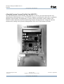
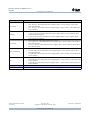
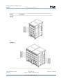
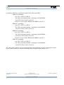
Motherboard Unit
The motherboard unit is the main circuit board in both midrange servers. The following components
connect to the motherboard unit:
•
CPU modules (two CPU chips per module)
•
Memory boards
•
Bus bar, I/O backplane, and power backplane unit (SPARC Enterprise M5000 server only)
•
I/O unit(s) through the I/O backplane
•
eXtended System Control Facility Unit (XSCFU) through the bus bar, I/O backplane, and
power backplane unit
To remove and replace the motherboard and these components, you must power the server off.
Removing the Motherboard Assembly From the SPARC Enterprise M5000 Server
Technical Development Centre
Version 2.1
Page 40 of 327
Copyright © Sun Microsystems Ltd., 2008
Sun Proprietary and Confidential
Issue Date : August 2008
Sun Sparc Enterprise MX000 Servers
TDC008
Sun Proprietary and Confidential
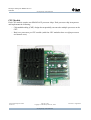
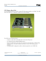
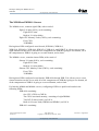
CPU Module
Each CPU module contains two SPARC64 VI processor chips. Each processor chip incorporates
and implements the following:
•
Chip multithreading (CMT) design that sequentially executes the multiple processes on the
CPU
•
Dual core processors per CPU module (with four CPU modules there are eight processors
and sixteen cores)
Technical Development Centre
Version 2.1
Page 41 of 327
Copyright © Sun Microsystems Ltd., 2008
Sun Proprietary and Confidential
Issue Date : August 2008
Sun Sparc Enterprise MX000 Servers
TDC008
Sun Proprietary and Confidential
The CPU modules can be accessed from the top of the midrange server.
CPU Module Features
Number of cores per CPU
2
CPU module location
Top of server
Cold FRU replacement capability Yes
CPU Modules in the SPARC Enterprise M4000 Server
The CPUM are cold-FRU removal components. The M4000 server contains
two CPUMs:
●
●
CPUM 0
CPUM 1
Technical Development Centre
Version 2.1
Page 42 of 327
Copyright © Sun Microsystems Ltd., 2008
Sun Proprietary and Confidential
Issue Date : August 2008
Sun Sparc Enterprise MX000 Servers
TDC008
Sun Proprietary and Confidential
CPU Modules in the SPARC Enterprise M5000 Server
The M5000 server contains four CPUMs:
● CPUM 0
● CPUM 1
● CPUM 2
● CPUM 3
Technical Development Centre
Version 2.1
Page 43 of 327
Copyright © Sun Microsystems Ltd., 2008
Sun Proprietary and Confidential
Issue Date : August 2008
Sun Sparc Enterprise MX000 Servers
TDC008
Sun Proprietary and Confidential
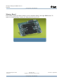
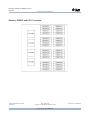
Memory Board
Each memory board provides a memory access controller (MAC) and eight DIMM slots. To
remove or install memory boards, you must power the server off.
Technical Development Centre
Version 2.1
Page 44 of 327
Copyright © Sun Microsystems Ltd., 2008
Sun Proprietary and Confidential
Issue Date : August 2008
Sun Sparc Enterprise MX000 Servers
TDC008
Sun Proprietary and Confidential
Technical Development Centre
Version 2.1
Page 45 of 327
Copyright © Sun Microsystems Ltd., 2008
Sun Proprietary and Confidential
Issue Date : August 2008
Sun Sparc Enterprise MX000 Servers
TDC008
Sun Proprietary and Confidential
Memory Board Features
Location
Top of server
Cold FRU replacement capability Yes
To install DIMMs, you must remove the memory board and open the case of the memory board.
The servers use Double Data Rate II (DDR-II) type memory with the following features:
•
ECC error protection
•
Recovery from memory chip failures
•
Memory Mirroring
Each memory board provides a MAC and eight DIMM slots. The MEMB are cold-FRU removal
components. To remove or install memory boards, you must power the system off.
Technical Development Centre
Version 2.1
Page 46 of 327
Copyright © Sun Microsystems Ltd., 2008
Sun Proprietary and Confidential
Issue Date : August 2008
Sun Sparc Enterprise MX000 Servers
TDC008
Sun Proprietary and Confidential
Memory Board Location in the SPARC Enterprise M4000 Server
Memory Board Location in the SPARC Enterprise M5000 Server
Technical Development Centre
Version 2.1
Page 47 of 327
Copyright © Sun Microsystems Ltd., 2008
Sun Proprietary and Confidential
Issue Date : August 2008
Sun Sparc Enterprise MX000 Servers
TDC008
Sun Proprietary and Confidential
Fan
Both midrange servers use 172-mm fans as the primary cooling system.
The fans in both midrange servers move air currents into and out of the server. The fans in both
midrange servers are redundant. Because of the redundancy, system operation continues when a
failure occurs with one fan. If the midrange server has at two fans of each fan type, one fan of each
fan type is redundant. If the midrange server has a total of four fans, two of the four fans are
redundant. Fan failures can be detected by the eXtended System Control Facility (XSCF).
The fans are accessed from the top of the midrange server.
Fan Locations in the SPARC Enterprise M4000 Server.
Callout Number
Description
1
Fans (2), 60-mm
2
Fans, 172-mm (M4000-2, M5000-4)
Technical Development Centre
Version 2.1
Page 48 of 327
Copyright © Sun Microsystems Ltd., 2008
Sun Proprietary and Confidential
Issue Date : August 2008
Sun Sparc Enterprise MX000 Servers
TDC008
Sun Proprietary and Confidential
Fan Locations in the SPARC Enterprise M5000 Server.
Callout Number
1
Description
Fans, 172-mm (M4000-2, M5000-4)
Technical Development Centre
Version 2.1
Page 49 of 327
Copyright © Sun Microsystems Ltd., 2008
Sun Proprietary and Confidential
Issue Date : August 2008
Sun Sparc Enterprise MX000 Servers
TDC008
Sun Proprietary and Confidential
Power Supply
Power is provided to both midrange servers by power supply units.
Power Supply Units in the SPARC Enterprise M4000 Server.
Callout Number
1
Description
Power supply units
Technical Development Centre
Version 2.1
Page 50 of 327
Copyright © Sun Microsystems Ltd., 2008
Sun Proprietary and Confidential
Issue Date : August 2008
Sun Sparc Enterprise MX000 Servers
TDC008
Sun Proprietary and Confidential
Power Supply Units in the SPARC Enterprise M5000 Server.
Callout Number
1
Description
Power supply units
The redundant power supplies allow continued server operation if a power supply fails. If the
system has two power supplies, one power supply is redundant and two power cords are required
for redundancy. If the system has four power supply units, two power supply units are redundant
and four power cords are required for redundancy. There is one power cord per power supply unit.
You can remove a power supply while the domain is operating (hot FRU removal).
Technical Development Centre
Version 2.1
Page 51 of 327
Copyright © Sun Microsystems Ltd., 2008
Sun Proprietary and Confidential
Issue Date : August 2008
Sun Sparc Enterprise MX000 Servers
TDC008
Sun Proprietary and Confidential
Power Supply Features
SPARC Enterprise M5000 Server
Hot FRU removal/replacement
capability
Yes (from front)
Redundant AC input
Yes
Input Current--Voltage Range
100-240 VAC
Input Current (maximum)
23.4A at 200 VAC (11.7A/cord)
Input Current--Frequency Range
50/60 Hz
Power Factor
0.98
Technical Development Centre
Version 2.1
Page 52 of 327
Copyright © Sun Microsystems Ltd., 2008
Sun Proprietary and Confidential
Issue Date : August 2008
Sun Sparc Enterprise MX000 Servers
TDC008
Sun Proprietary and Confidential
Operator Panel
The operator panel, which is not redundant, displays the system status, system problem alerts, and
location of system faults. It also stores the system identification and user setting information.
Callout Number
Function
1
Operator panel (FRU)
2
Power LED
3
Standby LED
4
Check LED
5
POWER button
6
MODE switch
Technical Development Centre
Version 2.1
Page 53 of 327
Copyright © Sun Microsystems Ltd., 2008
Sun Proprietary and Confidential
Issue Date : August 2008
Sun Sparc Enterprise MX000 Servers
TDC008
Sun Proprietary and Confidential
eXtended System Control Facility Unit (XSCFU)
The eXtended System Control Facility Unit (XSCFU) is a service processor that operates and
administrates both midrange servers. The XSCFU diagnoses and starts the entire server, configures
domains, offers dynamic reconfiguration, as well as detects and notifies various failures. The
XSCFU enables standard control and monitoring function through network. Using this function
enables starts, settings, and operation managements of the server from remote locations.
Technical Development Centre
Version 2.1
Page 54 of 327
Copyright © Sun Microsystems Ltd., 2008
Sun Proprietary and Confidential
Issue Date : August 2008
Sun Sparc Enterprise MX000 Servers
TDC008
Sun Proprietary and Confidential
XSCFU Location in the SPARC Enterprise M4000 Server
XSCFU Location in the SPARC Enterprise M5000 Server
Technical Development Centre
Version 2.1
Page 55 of 327
Copyright © Sun Microsystems Ltd., 2008
Sun Proprietary and Confidential
Issue Date : August 2008
Sun Sparc Enterprise MX000 Servers
TDC008
Sun Proprietary and Confidential
The XSCFU uses the eXtended System Control Facility (XSCF) firmware to provide the following
functions:
•
Controls and monitors the main unit hardware
•
Monitors the Solaris OS, power-on self-test (POST), and the OpenBoot PROM
•
Controls and manages the interface for the system administrator (such as a terminal console)
•
Administrators device information
•
Controls remote messaging of various events
Both midrange servers have one XSCFU, which is serviced from the rear of the server. To replace
it, you must power off the server. For more information, refer to the SPARC Enterprise
M4000/M5000 Servers Service Manual.
The XSCF firmware provides the system control and monitoring interfaces listed below.
•
Serial port through which the command line interface (XSCF shell) can be used
•
Two LAN ports:
•
XSCF shell
•
XSCF Web (browser-based user interface)
The following additional interfaces for system control are also provided:
•
The uninterruptible power supply unit (UPC) interface ports (2), which are used to
communicate to uninterruptible power supply units (UPS)
•
RCI port, which is used for power supply synchronization through a connected remote
cabinet interface (RCI) device
•
USB interface port for maintenance operator
•
This is dedicated for use by field engineers and cannot be connected to generalpurpose USB devices.
Technical Development Centre
Version 2.1
Page 56 of 327
Copyright © Sun Microsystems Ltd., 2008
Sun Proprietary and Confidential
Issue Date : August 2008
Sun Sparc Enterprise MX000 Servers
TDC008
Sun Proprietary and Confidential
I/O Unit
Four PCI Express (PCIe) buses are connected from one I/O controller. These buses support all of
the systems on-board I/O controllers in addition to the interface cards in the server.
I/O unit in the M4000 server
I/O Unit Locations in the SPARC Enterprise M5000 Server.
Technical Development Centre
Version 2.1
Page 57 of 327
Copyright © Sun Microsystems Ltd., 2008
Sun Proprietary and Confidential
Issue Date : August 2008
Sun Sparc Enterprise MX000 Servers
TDC008
Sun Proprietary and Confidential
Callout Number Description
1
I/O unit
The I/O unit (IOU) is used in the both midrange servers.
The IOU houses the following:
•
Four PCIe 8lane, x8 short card slots (four upper slots)
•
One PCI-X short card slot (lowest slot)
The IOU holds cassettes that supports both PCIe and PCI-X cards.
The PCIe features include a high-speed serial point-to-point interconnect. Compared with
conventional PCI buses, the PCIe data transfer rates are doubled. PCI-X is the current PCI standard.
Technical Development Centre
Version 2.1
Page 58 of 327
Copyright © Sun Microsystems Ltd., 2008
Sun Proprietary and Confidential
Issue Date : August 2008
Sun Sparc Enterprise MX000 Servers
TDC008
Sun Proprietary and Confidential
On-Board Drive Units
Both midrange servers provide front-panel access to the drives. The following drives are provided
on both midrange servers:
•
Hard disk drive units
•
One tape drive unit (optional)
•
One DVD drive unit
Hard Disk Drive, Tape Drive, and DVD Drive Units in the SPARC Enterprise M4000 Server
Callout Number
Description
1
DVD drive
2
Hard disk drive
3
Tape drive
Technical Development Centre
Version 2.1
Page 59 of 327
Copyright © Sun Microsystems Ltd., 2008
Sun Proprietary and Confidential
Issue Date : August 2008
Sun Sparc Enterprise MX000 Servers
TDC008
Sun Proprietary and Confidential
Hard Disk Drive, Tape Drive, and DVD Drive Units in the SPARC Enterprise M5000 Server Figure
noting the location of the hard disk drive, tape drive, and DVD drive in the SPARC Enterprise
M5000 server
Callout Number
Description
1
DVD drive
2
Hard disk drive
3
Tape drive
Technical Development Centre
Version 2.1
Page 60 of 327
Copyright © Sun Microsystems Ltd., 2008
Sun Proprietary and Confidential
Issue Date : August 2008
Sun Sparc Enterprise MX000 Servers
TDC008
Sun Proprietary and Confidential
Hard Disk Drive
The hard disk drives are located on the front of the midrange server. The SAS interface on the hard
disk drive allows a faster data transmission rate.
DVD Drive
DVD Drive Features and Specifications for Both Servers
Number of DVD drives 1
Location
Front of server to the right of the disk
drives
Hot FRU replacement
No
The Advanced Technology Attachment Packet Interface (ATAPI) is an interface between the server
and the DVD drive unit.
Technical Development Centre
Version 2.1
Page 61 of 327
Copyright © Sun Microsystems Ltd., 2008
Sun Proprietary and Confidential
Issue Date : August 2008
Sun Sparc Enterprise MX000 Servers
TDC008
Sun Proprietary and Confidential
Tape Drive Unit
The tape drive unit in both midrange servers is an optional components.
Tape Drive Unit Features and Specifications for Both Midrange Servers
Feature
Quantity, Location, and Specifications
Number of tape drive units
1 (optional)
Location
Front of server
Active FRU replacement capability Yes
Tape drive unit type
Digital audio tape (DAT) drive
Data transfer rate
About 6 MB/s
36 Gbytes of data (non compressed format)
Capacity
72 Gbytes of data (double-compressed format)
Media type
Sequential access
Transfer rate
150 MB/s or faster
Technical Development Centre
Version 2.1
Page 62 of 327
Copyright © Sun Microsystems Ltd., 2008
Sun Proprietary and Confidential
Issue Date : August 2008
Sun Sparc Enterprise MX000 Servers
TDC008
Sun Proprietary and Confidential
I/O Options
External I/O Expansion Unit
You can purchase an optional External I/O Expansion Unit to add I/O capacity to the server.
For installation and service of the unit see the Sun External I/O Expansion Unit Installation and
Service Manual 819-1141-xx at docs.sun.com
Technical Development Centre
Version 2.1
Page 63 of 327
Copyright © Sun Microsystems Ltd., 2008
Sun Proprietary and Confidential
Issue Date : August 2008
Sun Sparc Enterprise MX000 Servers
TDC008
Sun Proprietary and Confidential
Technical Development Centre
Version 2.1
Page 64 of 327
Copyright © Sun Microsystems Ltd., 2008
Sun Proprietary and Confidential
Issue Date : August 2008
Sun Sparc Enterprise MX000 Servers
TDC008
Sun Proprietary and Confidential
PCI Cards
Each PCI card in the server must be mounted to a PCI cassette before the card can be inserted into
the I/O unit slot.
Technology BUS SPEED BUS WIDTH BANDWIDTH
Comments
PCI
Shared bus
33MHz
33MHz
66MHz
66MHz
32 bit
64 bit
32 bit
64 bit
133 MB/s
266 MB/s
266 MB/s
532 MB/s
PCI-X
Shared bus
66MHz
100MHz
133MHz
266MHz
64 bit
64 bit
64 bit
64 bit
512 MB/s
800MB/s
1GB/s
2GB/s
PCI Express
Switched point to point
X1
X2
X4
X8
X12
X16
X32
Technical Development Centre
Version 2.1
4Gbps (500 MB/s)
8Gbps (1GBps)
16Gbps (2GBps)
32Gbps (4GBps)
48Gbps (6GBps)
64Gbps (8GBps)
128Gbps (16GBps)
Page 65 of 327
Copyright © Sun Microsystems Ltd., 2008
Sun Proprietary and Confidential
Issue Date : August 2008
Sun Sparc Enterprise MX000 Servers
TDC008
Sun Proprietary and Confidential
PCI Cassette
PCI Shared Bus
Technical Development Centre
Version 2.1
PCI EXPRESS Point2Point
Page 66 of 327
Copyright © Sun Microsystems Ltd., 2008
Sun Proprietary and Confidential
Issue Date : August 2008
Sun Sparc Enterprise MX000 Servers
TDC008
Sun Proprietary and Confidential
Software Features
The Solaris Operating System (Solaris OS) is installed on the system domains. In addition to its
suite of software capabilities, Solaris OS provides functions that interact with system hardware.
•
Dynamic Reconfiguration
•
Solaris zones
•
PCI hot-plug
•
Capacity on Demand
Both midrange servers use the eXtended System Control Facility (XSCF) firmware. This firmware
runs on the service processor and provides control and monitoring functions for the system
platform.
Technical Development Centre
Version 2.1
Page 67 of 327
Copyright © Sun Microsystems Ltd., 2008
Sun Proprietary and Confidential
Issue Date : August 2008
Sun Sparc Enterprise MX000 Servers
TDC008
Sun Proprietary and Confidential
M4000 Server Components
Technical Development Centre
Version 2.1
Page 68 of 327
Copyright © Sun Microsystems Ltd., 2008
Sun Proprietary and Confidential
Issue Date : August 2008
Sun Sparc Enterprise MX000 Servers
TDC008
Sun Proprietary and Confidential
Technical Development Centre
Version 2.1
Page 69 of 327
Copyright © Sun Microsystems Ltd., 2008
Sun Proprietary and Confidential
Issue Date : August 2008
Sun Sparc Enterprise MX000 Servers
TDC008
Sun Proprietary and Confidential
Technical Development Centre
Version 2.1
Page 70 of 327
Copyright © Sun Microsystems Ltd., 2008
Sun Proprietary and Confidential
Issue Date : August 2008
Sun Sparc Enterprise MX000 Servers
TDC008
Sun Proprietary and Confidential
M5000 Server Components
Technical Development Centre
Version 2.1
Page 71 of 327
Copyright © Sun Microsystems Ltd., 2008
Sun Proprietary and Confidential
Issue Date : August 2008
Sun Sparc Enterprise MX000 Servers
TDC008
Sun Proprietary and Confidential
Technical Development Centre
Version 2.1
Page 72 of 327
Copyright © Sun Microsystems Ltd., 2008
Sun Proprietary and Confidential
Issue Date : August 2008
Sun Sparc Enterprise MX000 Servers
TDC008
Sun Proprietary and Confidential
Technical Development Centre
Version 2.1
Page 73 of 327
Copyright © Sun Microsystems Ltd., 2008
Sun Proprietary and Confidential
Issue Date : August 2008
Sun Sparc Enterprise MX000 Servers
TDC008
Sun Proprietary and Confidential
M8000/M9000 Product Overview
SPARC Enterprise M8000/M9000 servers have been developed as UNIX servers using a symmetric
multi-processing (SMP) architecture. Each of these systems merges mainframe technologies for
high reliability, and the associated know-how accumulated over time, with the high-speed
technologies of super computers and the openness of UNIX server development.
If a problem occurs during operation, the errors causing them can be corrected or isolated without
stopping the system. This feature minimizes problems in many cases, thereby improving job
continuity.
Each SPARC Enterprise M8000/M9000 Servers contains one or more SPARC64 VI CPUs. They
can operate as multiple servers that permit flexible use of resources, including more efficient
execution of job operations.
Each server consists of a cabinet containing various mounted components, a front door, rear door,
and side covers as parts of the server structure.
An operator panel is mounted on the front door and is always accessible. Take special care in
handling and storing the dedicated key is provided for the front door and the operator panel.
Technical Development Centre
Version 2.1
Page 74 of 327
Copyright © Sun Microsystems Ltd., 2008
Sun Proprietary and Confidential
Issue Date : August 2008
Sun Sparc Enterprise MX000 Servers
TDC008
Sun Proprietary and Confidential
SPARC Enterprise M8000 Server Appearance
M9000 Server (Base Cabinet Only) Appearance
SPARC Enterprise M9000 Server (With an Expansion Cabinet) Appearance
Technical Development Centre
Version 2.1
Page 75 of 327
Copyright © Sun Microsystems Ltd., 2008
Sun Proprietary and Confidential
Issue Date : August 2008
Sun Sparc Enterprise MX000 Servers
TDC008
Sun Proprietary and Confidential
Sun SPARC Enterprise M8000 Details:
Software
Details
•
Operating System
Notes
•
Solaris 10
11/06 or later
Management Software
Extended System
Control Facility (XSCF)
Hardware
Details
•
•
•
HOTPLUG support will be available in Solaris 10 (U4), expected
July 2007.
Dynamic Reconfiguration (DR) will be available in Solaris 10 (U4),
expected July 2007.
The M8000 servers come with XSCF monitoring/control facility.
The XSCF software manages hardware configuration and health,
domain configuration and status, error monitor, and notification.
Notes
Processors are located on CPU/Memory Board Units (CMU). There are (4)
CMU board slots in the M8000 server. CMU's are available with either (2 or
4) processors.
•
Processors (CPU's)
Up to 16 Processors
•
•
•
•
•
•
Technical Development Centre
Version 2.1
Supported CPU/Memory Board Units (CMU) include:
• SPARC64 VI 2.4GHz dual-core processors with 6MB L2
cache.
• SPARC64 VI 2.28GHz dual-core processors with 5MB L2
cache.
A minimum of (1) 2-processor or 4-processor CMU is required per
M8000 server.
The M8000 server supports up to (16) domains.
A single CMU can be divided into multiple domains.
A minimum of (1) processor is required per domain.
Capacity on Demand (COD) CPU/Memory Board Units (CMU) are
available.
UltraSPARC 1V+ processors are not supported in the Sun SPARC
Enterprise M8000.
Page 76 of 327
Copyright © Sun Microsystems Ltd., 2008
Sun Proprietary and Confidential
Issue Date : August 2008
Sun Sparc Enterprise MX000 Servers
TDC008
Sun Proprietary and Confidential
Memory is located on CPU/Memory Board Units (CMU). There are (4) CMU
board slots in the M8000 server. There are (32) DIMM slots per CMU.
•
•
Memory
Maximum of 512GB
•
•
•
The (32) DIMM slots on a CMU is divided into Group A and Group
B.
CMU's come with (16) of the (32) DIMM slots populated (Group
A), but additional memory expansion kits can be added to the other
(16) DIMM slots (Group B) on the CMU. Additional memory being
added to a board can be added as factory installed (ATO) or for field
install (PTO).
Memory Expansion Kits being added to Group B cannot be larger
capacity kits than are installed in Group A on a CMU.
Memory added to a CMU must be added (16) DIMM's at a time.
Supported Memory Expansion Kits include 16GB(16x1GB),
32GB(16x2GB) and, 64GB(16x4GB).
Internal PCI-E slots are located in the Internal I/O Units (IOU). Up to (4)
IOU's can be installed into an M8000 server.
•
•
•
•
•
•
Internal I/O Expansion
Slots
Up to 32 PCI-E slots
(via 4 IOU's)
•
Each IOU has (8) PCI-E slots.
PCI-E slots in the IOU are x8 PCI-E slots.
IMPORTANT: The M8000 server also has (4) CPU/Memory
Board Unit (CMU) slots, and to configure an IOU in the M8000 the
corresponding CMU in the server must also be present. This means
there must be at least as many CMU's in the server as IOU's. There
can be more CMU's than IOU's in the server, but not vice versa.
Each IOU also has (4) SAS disk drive bays.
A PCI-E "Base I/O Card" is required (installed in slot 0 of the IOU)
to support the first two SAS disk drives in the IOU.
Another PCI-E "Base I/O Card" is required (installed in slot 4 of
the IOU) to support the third and fourth SAS disk drives in the IOU.
A PCI-E "Base I/O Card" is also required (installed in an even
numbered slot in the IOU) to support the DVD-ROM and the DAT
drive in the M8000 (the DAT drive is optional, but the DVD-ROM
comes standard with all M8000 servers). If a PCI-E "Base I/O Card
is already configured to support any SAS disk drives being added,
then that base I/O Card can also be used for the DVD-ROM and
DAT drive thus not requiring the addition of another card.
Additional Notes:
•
•
Technical Development Centre
Version 2.1
(1) PCI-E slot in an IOU will be needed for each "Optical Link
Card" being used to connect "External I/O Expansion Units" to the
M8000 server. (1) Optical Link Card is needed for each I/O Boat of
an External I/O Expansion Unit.
Optical Link Cards need to be installed in an odd number slots in the
IOU. A max of (4) Optical Link Cards are supported in an IOU.
Page 77 of 327
Copyright © Sun Microsystems Ltd., 2008
Sun Proprietary and Confidential
Issue Date : August 2008
Sun Sparc Enterprise MX000 Servers
TDC008
Sun Proprietary and Confidential
Up to (8) External I/O Expansion Units can be connected to an M8000 server.
•
External I/O Expansion
Slots
Up to 96 PCI-E or PCI-X
slots
(via 8 External I/O
Expansion Units)
•
•
•
•
Each External I/O Expansion Unit houses (1 or 2) PCI-E or PCI-X I/
O Boats.
Each I/O Boat has (6) PCI-E or (6) PCI-X slots.
PCI-E and PCI-X I/O Boats can be mixed within an External I/O
Expansion Tray.
(1) PCI-E slot in an IOU will be needed for each "Optical Link
Card" being used to connect "External I/O Expansion Units" to the
M8000 server. (1) Optical Link Card is needed for each I/O Boat of
an External I/O Expansion Unit.
Optical Link Cards need to be installed in an odd number slots in the
IOU. A max of (4) Optical Link Cards are supported in an IOU.
The Sun SPARC Enterprise M8000 servers come with a XSCF
monitoring/control facility, which consists of a dedicated processor that is
independent from the system processor.
RAS Management
Extended System
Control Facility (XSCF)
•
•
•
•
•
•
•
•
Internal Disk Drives
Up to 16 SAS Disk
Drives
•
•
•
•
•
Technical Development Centre
Version 2.1
The XSCF firmware runs on the service processor system.
The board with the installed XSCF firmware is called the XSCF unit
(XSCFU).
The SPARC Enterprise M8000 servers are configured with
redundant XSCF units.
Supports 73GB 10K RPM, and 146GB 10K RPM 2.5" SAS disk
drives.
SAS disk drives are located in the I/O Units (IOU) of the M8000
server.
Each IOU also has (4) SAS disk drive bays.
Either (2 or 4) SAS disk drives are supported in an IOU (must
always be installed in pairs).
Supports mixing of 73GB, and 146GB 10K RPM 2.5" SAS disk
drives (must always be installed in pairs).
Minimum of (2) internal disks per system, however both disks are
not required to be for the same base IO card.
Boot disks required for minimum of (1) domain, however they are
not required for each domain.
The SAS disk drives are controlled by a PCI-E "Base I/O Card"
installed in the IOU.
A PCI-E "Base I/O Card" is required (installed in slot 0 of the IOU)
to support the first two SAS disk drives in the IOU.
Another PCI-E "Base I/O Card" is required (installed in slot 4 of
the IOU) to support the third and fourth SAS disk drives in the IOU.
Page 78 of 327
Copyright © Sun Microsystems Ltd., 2008
Sun Proprietary and Confidential
Issue Date : August 2008
Sun Sparc Enterprise MX000 Servers
TDC008
Sun Proprietary and Confidential
•
•
•
Internal DVD-ROM
Includes DVD-ROM
•
•
Internal Tape Drive
Optional DAT72 Tape
Drive
Internal Floppy Drive
None
External Ports
Details
SCSI
None
Fibre Channel
None
•
•
Ethernet
None
None
Technical Development Centre
Version 2.1
A PCI-E "Base I/O Card" is needed to support the optional DAT72
tape drive.
If a PCI-E "Base I/O Card is already configured to support any SAS
disk drives being added, then that base I/O Card can also be used
for the DVD-ROM and DAT drive thus not requiring the addition of
another card.
There is no floppy drive support on the Sun SPARC Enterprise
M8000.
Notes
•
No built-in SCSI ports, additional HBA would be needed.
•
No built-in fibre channel ports, additional HBA would be needed.
•
There are no built-in general purpose network ports. Network ports
are provided via the PCI-E "Base I/O Card", and other PCI/PCI-E
network adapters.
Each PCI-E "Base I/O Card" has (2) gigabit ethernet ports.
The redundant Extended System Control Facility Units (XSCFU) n
the M8000 have (2) 10/100 ethernet ports that are used for system
management.
•
•
•
•
Serial
Each M8000 server base includes a DVD-ROM
A PCI-E "Base I/O Card" is required (installed in an even
numbered slot in the IOU) to support the DVD-ROM (and the
optional DAT drive) in the M8000 server.
If a PCI-E "Base I/O Card is already configured to support any SAS
disk drives being added, then that base I/O Card can also be used
for the DVD-ROM and DAT drive thus not requiring the addition of
another card.
The DVD drive cannot be directly shared by multiple domains.
However, if the multiple domains are connected to one another
through a LAN and a certain function of the Solaris Operating
System is used, the DVD drive can be shared by the domains.
Adequate consideration of security is necessary before you
configure LAN connections between domains.
There are no built-in general purpose serial ports.
The redundant Extended System Control Facility Units (XSCFU) in
the M8000 have (1) RJ45 serial port that are used for system
management.
Page 79 of 327
Copyright © Sun Microsystems Ltd., 2008
Sun Proprietary and Confidential
Issue Date : August 2008
Sun Sparc Enterprise MX000 Servers
TDC008
Sun Proprietary and Confidential
•
•
There are no built-in general purpose USB ports.
The redundant Extended System Control Facility Units (XSCFU) in
the M8000 have (1) USB port that a field engineer can use to
download hardware information.
USB
None
Keyboard
None
Video
None
External Storage
Details
Disk Storage
D240, 2540, FLX280, 3120, 3320, 3510, 3511, 5320 NAS, 6140, 6540, FLX380, 9910, 9960, 9970,
9980, 9985, 9990
Tape Storage
DAT72 USB Desktop, DAT72 Desktop, DAT72 Rackmount, SDLT320 Desktop, SDLT600 Desktop,
SDLT600 Rackmount, LTO3 Desktop, LTO3 Rackmount, L20, L40, L80, C2, C4, L180, L700, L1400,
SL500 (LTO), SL500 (Mixed Media), SL8500
Supported Boot Devices Details
Internal SAS disk drives located in I/O Units (IOU) of M8000 server.
•
•
Primary Boot Device
•
SAS disk drives are installed in pairs and are mirrored.
The M8000 supports up to (16) internal SAS disk drives thus providing enough internal boot
disks for (8) domains.
External boot devices would also be needed for M8000 servers being configured with more
than (8) domains.
Sun StorageTek 2540
Additional Supported
Boot Devices
Sun StorageTek 3120
Sun StorageTek 3510
Sun StorageTek 9985
Sun StorageTek 9990
Physical Specs
Details
Height
•
•
70.9" (180 cm) Base Cabinet
70.9" (180 cm) Base Cabinet + Power Cabinet
Width
•
•
29.5" (75 cm) Base Cabinet
41.5" (105.4 cm) Base Cabinet + Power Cabinet
Depth
•
•
49.6" (126 cm) Base Cabinet
49.6" (126 cm) Base Cabinet + Power Cabinet
Weight
•
•
1543.2 lbs (700 kg) Base Cabinet
2248.7 lbs (1020 kg) Base Cabinet + Power Cabinet
Technical Development Centre
Version 2.1
Page 80 of 327
Copyright © Sun Microsystems Ltd., 2008
Sun Proprietary and Confidential
Issue Date : August 2008
Sun Sparc Enterprise MX000 Servers
TDC008
Sun Proprietary and Confidential
Electrical Specs
Details
•
•
Input Voltage
•
•
•
VA Rating
•
•
•
Input Current
•
•
•
Power Consumption
•
•
•
BTU
•
200 - 240 VAC, with 4 CMUs and 4 IOUs installed.
200 - 240 VAC, Three-Phase Delta Power Supplies (Base + Power Cabinet), with 4 CMUs
and 4 IOUs installed.
380 - 415 VAC, Three-Phase Star Power Supplies (Base + Power Cabinet), with 4 CMUs and
4 IOUs installed.
11,000 VA @ 200 VAC, Base Cabinet, with 4 CMUs and 4 IOUs installed.
11,000 VA @ 200 VAC, Three-Phase Delta Power Supplies (Base + Power Cabinet), with 4
CMUs and 4 IOUs installed.
10,982 VA @ 380 VAC, Three-Phase Star Power Supplies (Base + Power Cabinet), with 4
CMUs and 4 IOUs installed.
55 A @ 200 VAC, with 4 CMUs and 4 IOUs installed.
55 A @ 200 VAC, Three-Phase Delta Power Supplies (Base + Power Cabinet), with 4 CMUs
and 4 IOUs installed.
28.9 A @ 380 VAC, Three-Phase Star Power Supplies (Base + Power Cabinet), with 4 CMUs
and 4 IOUs installed.
10,500W (Max), Base Cabinet, with 4 CMUs and 4 IOUs installed.
10,500W (Max), Three-Phase Delta Power Supplies (Base + Power Cabinet), with 4 CMUs
and 4 IOUs installed.
10,500W (Max), Three-Phase Star Power Supplies (Base + Power Cabinet), with 4 CMUs and
4 IOUs installed.
35,847 BTU/hr, Base Cabinet, with 4 CMUs and 4 IOUs installed.
35,847 BTU/hr, Three-Phase Delta Power Supplies (Base + Power Cabinet), with 4 CMUs and
4 IOUs installed.
35,847 BTU/hr, Three-Phase Star Power Supplies (Base + Power Cabinet), with 4 CMUs and
4 IOUs installed.
Rack Info
Details
M8000 Server Cabinet
The M8000 server is a stand alone server in it's own enclosure (single cabinet).
Technical Development Centre
Version 2.1
Page 81 of 327
Copyright © Sun Microsystems Ltd., 2008
Sun Proprietary and Confidential
Issue Date : August 2008
Sun Sparc Enterprise MX000 Servers
TDC008
Sun Proprietary and Confidential
Sun SPARC Enterprise M9000-32 Details:
Software
Details
Notes
•
•
Operating System
Solaris 10
11/06 or later
•
•
Management Software
Extended System
Control Facility (XSCF)
Hardware
Details
•
•
Full compatibility with existing applications running on earlier
versions of Solaris OS..
HOTPLUG support will be available in Solaris 10 (U4), expected
July 2007.
Dynamic Reconfiguration (DR) will be available in Solaris 10 (U4),
expected July 2007.
The M9000 servers come with XSCF monitoring/control facility.
The XSCF software manages hardware configuration and health,
domain configuration and status, error monitor, and notification.
Notes
Processors are located on CPU/Memory Board Units (CMU). There are (8)
CMU board slots in the M9000-32 server. CMU's are available with either (2
or 4) processors.
•
Processors (CPU's)
Up to 32 Processors
•
•
•
•
•
•
Technical Development Centre
Version 2.1
Supported CPU/Memory Board Units (CMU) include:
• SPARC64 VI 2.4GHz dual-core processors with 6MB L2
cache.
• SPARC64 VI 2.28GHz dual-core processors with 5MB L2
cache.
A minimum of (1) 2-processor or 4-processor CMU is required per
M9000-32 server.
The M9000-32 server supports up to (24) domains.
A single CMU can be divided into multiple domains.
A minimum of (1) processor is required per domain.
Capacity on Demand (COD) CPU/Memory Board Units (CMU) are
available.
UltraSPARC 1V+ processors are not supported in the Sun SPARC
Enterprise M8000.
Page 82 of 327
Copyright © Sun Microsystems Ltd., 2008
Sun Proprietary and Confidential
Issue Date : August 2008
Sun Sparc Enterprise MX000 Servers
TDC008
Sun Proprietary and Confidential
Memory is located on CPU/Memory Board Units (CMU). There are (8) CMU
board slots in the M9000-32 server. There are (32) DIMM slots per CMU.
•
•
Memory
Maximum of 1024GB
•
•
•
The (32) DIMM slots on a CMU is divided into Group A and Group
B.
CMU's come with (16) of the (32) DIMM slots populated (Group
A), but additional memory expansion kits can be added to the other
(16) DIMM slots (Group B) on the CMU. Additional memory being
added to a board can be added as factory installed (ATO) or for field
install (PTO).
Memory Expansion Kits being added to Group B cannot be larger
capacity kits than are installed in Group A on a CMU.
Memory added to a CMU must be added (16) DIMM's at a time.
Supported Memory Expansion Kits include 16GB(16x1GB),
32GB(16x2GB) and, 64GB(16x4GB).
Internal PCI-E slots are located in the Internal I/O Units (IOU). Up to (8)
IOU's can be installed into an M9000-32 server.
•
•
•
•
•
•
Internal I/O Expansion
Slots
Up to 64 PCI-E slots
(via 8 IOU's)
•
Each IOU has (8) PCI-E slots.
PCI-E slots in the IOU are x8 PCI-E slots.
IMPORTANT: The M9000-32 server also has (8) CPU/Memory
Board Unit (CMU) slots, and to configure an IOU in the M9000-32
the corresponding CMU in the server must also be present. This
means there must be at least as many CMU's in the server as IOU's.
There can be more CMU's than IOU's in the server, but not vice
versa.
Each IOU also has (4) SAS disk drive bays.
A PCI-E "Base I/O Card" is required (installed in slot 0 of the IOU)
to support the first two SAS disk drives in the IOU.
Another PCI-E "Base I/O Card" is required (installed in slot 4 of
the IOU) to support the third and fourth SAS disk drives in the IOU.
A PCI-E "Base I/O Card" is also required (installed in an even
numbered slot in the IOU) to support the DVD-ROM and the DAT
drive in the M9000-32 (the DAT drive is optional, but the DVDROM comes standard with all M9000-32 servers). If a PCI-E "Base
I/O Card is already configured to support any SAS disk drives being
added, then that base I/O Card can also be used for the DVD-ROM
and DAT drive thus not requiring the addition of another card.
Additional Notes:
•
•
Technical Development Centre
Version 2.1
(1) PCI-E slot in an IOU will be needed for each "Optical Link
Card" being used to connect "External I/O Expansion Units" to the
M9000-32 server. (1) Optical Link Card is needed for each I/O Boat
of an External I/O Expansion Unit.
Optical Link Cards need to be installed in an odd number slots in the
IOU. A max of (4) Optical Link Cards are supported in an IOU.
Page 83 of 327
Copyright © Sun Microsystems Ltd., 2008
Sun Proprietary and Confidential
Issue Date : August 2008
Sun Sparc Enterprise MX000 Servers
TDC008
Sun Proprietary and Confidential
Up to (16) External I/O Expansion Units can be connected to an M9000-32
server.
•
External I/O Expansion
Slots
Up to 192 PCI-E or PCIX slots
(via 16 External I/O
Expansion Units)
•
•
•
•
Each External I/O Expansion Unit houses (1 or 2) PCI-E or PCI-X I/
O Boats.
Each I/O Boat has (6) PCI-E or (6) PCI-X slots.
PCI-E and PCI-X I/O Boats can be mixed within an External I/O
Expansion Tray.
(1) PCI-E slot in an IOU will be needed for each "Optical Link
Card" being used to connect "External I/O Expansion Units" to the
M9000-32 server. (1) Optical Link Card is needed for each I/O Boat
of an External I/O Expansion Unit.
Optical Link Cards need to be installed in an odd number slots in the
IOU. A max of (4) Optical Link Cards are supported in an IOU.
The Sun SPARC Enterprise M9000 servers come with a XSCF
monitoring/control facility, which consists of a dedicated processor that is
independent from the system processor.
RAS Management
Extended System
Control Facility (XSCF)
•
•
•
•
•
•
•
•
Internal Disk Drives
Up to 32 SAS Disk
Drives
•
•
•
•
•
Technical Development Centre
Version 2.1
The XSCF firmware runs on the service processor system.
The board with the installed XSCF firmware is called the XSCF unit
(XSCFU).
The SPARC Enterprise M8000 servers are configured with
redundant XSCF units.
Supports 73GB 10K RPM, and 146GB 10K RPM 2.5" SAS disk
drives.
SAS disk drives are located in the I/O Units (IOU) of the M9000
server.
Each IOU also has (4) SAS disk drive bays.
Either (2 or 4) SAS disk drives are supported in an IOU (must
always be installed in pairs).
Supports mixing of 73GB, and 146GB 10K RPM 2.5" SAS disk
drives (must always be installed in pairs).
Minimum of (2) internal disks per system, however both disks are
not required to be for the same base IO card.
Boot disks required for minimum of (1) domain, however they are
not required for each domain.
The SAS disk drives are controlled by a PCI-E "Base I/O Card"
installed in the IOU.
A PCI-E "Base I/O Card" is required (installed in slot 0 of the IOU)
to support the first two SAS disk drives in the IOU.
Another PCI-E "Base I/O Card" is required (installed in slot 4 of
the IOU) to support the third and fourth SAS disk drives in the IOU.
Page 84 of 327
Copyright © Sun Microsystems Ltd., 2008
Sun Proprietary and Confidential
Issue Date : August 2008
Sun Sparc Enterprise MX000 Servers
TDC008
Sun Proprietary and Confidential
•
•
•
Internal DVD-ROM
Includes DVD-ROM
•
•
Internal Tape Drive
Optional DAT72 Tape
Drive
Internal Floppy Drive
None
External Ports
Details
SCSI
None
Fibre Channel
None
•
•
Ethernet
None
None
Technical Development Centre
Version 2.1
A PCI-E "Base I/O Card" is needed to support the optional DAT72
tape drive.
If a PCI-E "Base I/O Card is already configured to support any SAS
disk drives being added, then that base I/O Card can also be used
for the DVD-ROM and DAT drive thus not requiring the addition of
another card.
There is no floppy drive support on the Sun SPARC Enterprise
M9000.
Notes
•
No built-in SCSI ports, additional HBA would be needed.
•
No built-in fibre channel ports, additional HBA would be needed.
•
There are no built-in general purpose network ports. Network ports
are provided via the PCI-E "Base I/O Card", and other PCI/PCI-E
network adapters.
Each PCI-E "Base I/O Card" has (2) gigabit ethernet ports.
The redundant Extended System Control Facility Units (XSCFU) in
the M9000 have (2) 10/100 ethernet ports that are used for system
management.
•
•
•
•
Serial
Each M9000 server base includes a DVD-ROM
A PCI-E "Base I/O Card" is required (installed in an even
numbered slot in the IOU) to support the DVD-ROM (and the
optional DAT drive) in the M9000 server.
If a PCI-E "Base I/O Card is already configured to support any SAS
disk drives being added, then that base I/O Card can also be used
for the DVD-ROM and DAT drive thus not requiring the addition of
another card.
The DVD drive cannot be directly shared by multiple domains.
However, if the multiple domains are connected to one another
through a LAN and a certain function of the Solaris Operating
System is used, the DVD drive can be shared by the domains.
Adequate consideration of security is necessary before you
configure LAN connections between domains.
There are no built-in general purpose serial ports.
The redundant Extended System Control Facility Units (XSCFU) in
the M9000 have (1) RJ45 serial port that are used for system
management.
Page 85 of 327
Copyright © Sun Microsystems Ltd., 2008
Sun Proprietary and Confidential
Issue Date : August 2008
Sun Sparc Enterprise MX000 Servers
TDC008
Sun Proprietary and Confidential
•
•
There are no built-in general purpose USB ports.
The redundant Extended System Control Facility Units (XSCFU) in
the M9000 have (1) USB port that a field engineer can use to
download hardware information.
USB
None
Keyboard
None
Video
None
External Storage
Details
Disk Storage
D240, 2540, FLX280, 3120, 3320, 3510, 3511, 5320 NAS, 6140, 6540, FLX380, 9910, 9960, 9970,
9980, 9985, 9990
Tape Storage
DAT72 USB Desktop, DAT72 Desktop, DAT72 Rackmount, SDLT320 Desktop, SDLT600 Desktop,
SDLT600 Rackmount, LTO3 Desktop, LTO3 Rackmount, L20, L40, L80, C2, C4, L180, L700, L1400,
SL500 (LTO), SL500 (Mixed Media), SL8500
Supported Boot Devices Details
Internal SAS disk drives located in I/O Units (IOU) of M9000-32 server.
•
•
Primary Boot Device
•
SAS disk drives are installed in pairs and are mirrored.
The M9000-32 supports up to (32) internal SAS disk drives thus providing enough internal
boot disks for (16) domains.
External boot devices would also be needed for M9000-32 servers being configured with more
than (16) domains.
Sun StorageTek 2540
Additional Supported
Boot Devices
Sun StorageTek 3120
Sun StorageTek 3510
Sun StorageTek 9985
Sun StorageTek 9990
Physical Specs
Details
Height
•
•
70.9" (180 cm) Base Cabinet
70.9" (180 cm) Base Cabinet + Power Cabinet (1-Phase or 3-phase power)
Width
•
•
33.5" (85 cm) Base Cabinet
45.4" (115.4 cm) Base Cabinet + Power Cabinet (1-Phase or 3-phase power)
Depth
•
•
49.6" (126 cm) Base Cabinet
49.6" (126 cm) Base Cabinet + Power Cabinet (1-Phase or 3-phase power)
Weight
•
•
1873.9 lbs (850 kg) Base Cabinet
2843.9 lbs (1290 kg) Base Cabinet + Power Cabinet (1-Phase or 3-phase power)
Technical Development Centre
Version 2.1
Page 86 of 327
Copyright © Sun Microsystems Ltd., 2008
Sun Proprietary and Confidential
Issue Date : August 2008
Sun Sparc Enterprise MX000 Servers
TDC008
Sun Proprietary and Confidential
Electrical Specs
Details
•
•
•
Input Voltage
•
•
•
•
VA Rating
•
•
•
•
Input Current
•
•
•
•
Power Consumption
•
•
•
•
BTU's
•
200 - 240 VAC Base Cabinet, with 8 CMUs and 8 IOUs installed.
200 - 240 VAC Base + Power Cabinet, with 8 CMUs and 8 IOUs installed.
200 - 240 VAC Three-Phase Delta Power Supplies (Base + Power Cabinet), with 8 CMUs and
8 IOUs installed.
380 - 415 VAC Three-Phase Star Power Supplies (Base + Power Cabinet), with 8 CMUs and 8
IOUs installed.
22,400 VA @ 200 VAC Base Cabinet, with 8 CMUs and 8 IOUs installed.
22,400 VA @ 200 VAC Base + Power Cabinet, with 8 CMUs and 8 IOUs installed.
22,400 VA @ 200 VAC Three-Phase Delta Power Supplies (Base + Power Cabinet), with 8
CMUs and 8 IOUs installed.
22,420 VA @ 380 VAC Three-Phase Star Power Supplies (Base + Power Cabinet), with 8
CMUs and 8 IOUs installed.
112A @ 200 VAC Base Cabinet, with 8 CMUs and 8 IOUs installed.
112A @ 200 VAC Base + Power Cabinet, with 8 CMUs and 8 IOUs installed.
112A @ 200 VAC Three-Phase Delta Power Supplies (Base + Power Cabinet), with 8 CMUs
and 8 IOUs installed.
59A @ 380 VAC Three-Phase Star Power Supplies (Base + Power Cabinet), with 8 CMUs
and 8 IOUs installed.
21,300W (Max) Base Cabinet, with 8 CMUs and 8 IOUs installed.
21,300W (Max) Base + Power Cabinet, with 8 CMUs and 8 IOUs installed.
21,300W (Max) Three-Phase Delta Power Supplies (Base + Power Cabinet), with 8 CMUs
and 8 IOUs installed.
21,300W (Max) Three-Phase Star Power Supplies (Base + Power Cabinet), with 8 CMUs and
8 IOUs installed.
72,718.2 BTU/hr Base Cabinet, with 8 CMUs and 8 IOUs installed.
72,718.2 BTU/hr Base + Power Cabinet, with 8 CMUs and 8 IOUs installed.
72,718.2 BTU/hr Three-Phase Delta Power Supplies (Base + Power Cabinet), with 8 CMUs
and 8 IOUs installed.
72,718.2 BTU/hr Three-Phase Star Power Supplies (Base + Power Cabinet), with 8 CMUs and
8 IOUs installed.
Rack Info
Details
M9000-32 Server
Cabinet
The M9000-32 server is a stand alone server in it's own enclosure (single cabinet).
Technical Development Centre
Version 2.1
Page 87 of 327
Copyright © Sun Microsystems Ltd., 2008
Sun Proprietary and Confidential
Issue Date : August 2008
Sun Sparc Enterprise MX000 Servers
TDC008
Sun Proprietary and Confidential
Sun SPARC Enterprise M9000-64 Details:
Software
Details
Notes
•
•
Operating System
Solaris 10
11/06 or later
•
•
Management Software
Extended System
Control Facility (XSCF)
Hardware
Details
•
•
Full compatibility with existing applications running on earlier
versions of Solaris OS..
HOTPLUG support will be available in Solaris 10 (U4), expected
July 2007.
Dynamic Reconfiguration (DR) will be available in Solaris 10 (U4),
expected July 2007.
The M9000 servers come with XSCF monitoring/control facility.
The XSCF software manages hardware configuration and health,
domain configuration and status, error monitor, and notification.
Notes
Processors are located on CPU/Memory Board Units (CMU). There are (16)
CMU board slots in the M9000-64 server (8 CMU slots per cabinet). CMU's
are available with either (2 or 4) processors.
•
Processors (CPU's)
Up to 64 Processors
•
•
•
•
•
•
Technical Development Centre
Version 2.1
Supported CPU/Memory Board Units (CMU) include:
• SPARC64 VI 2.4GHz dual-core processors with 6MB L2
cache.
• SPARC64 VI 2.28GHz dual-core processors with 5MB L2
cache.
A minimum of (1) 2-processor or 4-processor CMU is required per
M9000-64 server.
The M9000-64 server supports up to (24) domains.
A single CMU can be divided into multiple domains.
A minimum of (1) processor is required per domain.
Capacity on Demand (COD) CPU/Memory Board Units (CMU) are
available.
UltraSPARC 1V+ processors are not supported in the Sun SPARC
Enterprise M8000.
Page 88 of 327
Copyright © Sun Microsystems Ltd., 2008
Sun Proprietary and Confidential
Issue Date : August 2008
Sun Sparc Enterprise MX000 Servers
TDC008
Sun Proprietary and Confidential
Memory is located on CPU/Memory Board Units (CMU). There are (16) CMU
board slots in the M9000-64 server (8 CMU slots per cabinet). There are (32)
DIMM slots per CMU.
•
•
Memory
Maximum of 2048GB
•
•
•
Internal I/O Expansion
Slots
Up to 128 PCI-E slots
(via 16 IOU's)
The (32) DIMM slots on a CMU is divided into Group A and Group
B.
CMU's come with (16) of the (32) DIMM slots populated (Group A),
but additional memory expansion kits can be added to the other (16)
DIMM slots (Group B) on the CMU. Additional memory being
added to a board can be added as factory installed (ATO) or for field
install (PTO).
Memory Expansion Kits being added to Group B cannot be larger
capacity kits than are installed in Group A on a CMU.
Memory added to a CMU must be added (16) DIMM's at a time.
Supported Memory Expansion Kits include 16GB(16x1GB),
32GB(16x2GB) and, 64GB(16x4GB).
Internal PCI-E slots are located in the Internal I/O Units (IOU). Up to (16)
IOU's can be installed into an M9000-64 server (8 per cabinet).
•
•
•
•
•
•
•
Each IOU has (8) PCI-E slots.
PCI-E slots in the IOU are x8 PCI-E slots.
IMPORTANT: The M9000-64 server also has (16) CPU/Memory
Board Unit (CMU) slots, and to configure an IOU in the M9000-64
the corresponding CMU in the server must also be present. This
means there must be at least as many CMU's in the server as IOU's.
There can be more CMU's than IOU's in the server, but not vice
versa.
Each IOU also has (4) SAS disk drive bays.
A PCI-E "Base I/O Card" is required (installed in slot 0 of the IOU)
to support the first two SAS disk drives in the IOU.
Another PCI-E "Base I/O Card" is required (installed in slot 4 of the
IOU) to support the third and fourth SAS disk drives in the IOU.
A PCI-E "Base I/O Card" is also required (installed in an even
numbered slot in the IOU) to support the DVD-ROM and the DAT
drive in the M9000-64 (the DAT drive is optional, but the DVDROM comes standard with all M9000-64 servers). If a PCI-E "Base
I/O Card is already configured to support any SAS disk drives being
added, then that base I/O Card can also be used for the DVD-ROM
and DAT drive thus not requiring the addition of another card.
Additional Notes:
•
•
Technical Development Centre
Version 2.1
(1) PCI-E slot in an IOU will be needed for each "Optical Link
Card" being used to connect "External I/O Expansion Units" to the
M9000-64 server. (1) Optical Link Card is needed for each I/O Boat
of an External I/O Expansion Unit.
Optical Link Cards need to be installed in an odd number slots in the
Page 89 of 327
Copyright © Sun Microsystems Ltd., 2008
Sun Proprietary and Confidential
Issue Date : August 2008
Sun Sparc Enterprise MX000 Servers
TDC008
Sun Proprietary and Confidential
IOU. A max of (4) Optical Link Cards are supported in an IOU.
Up to (16) External I/O Expansion Units can be connected to an M9000-64
server.
•
External I/O Expansion
Slots
Up to 192 PCI-E or PCIX slots
(via 16 External I/O
Expansion Units)
•
•
•
•
Each External I/O Expansion Unit houses (1 or 2) PCI-E or PCI-X I/
O Boats.
Each I/O Boat has (6) PCI-E or (6) PCI-X slots.
PCI-E and PCI-X I/O Boats can be mixed within an External I/O
Expansion Tray.
(1) PCI-E slot in an IOU will be needed for each "Optical Link
Card" being used to connect "External I/O Expansion Units" to the
M9000-64 server. (1) Optical Link Card is needed for each I/O Boat
of an External I/O Expansion Unit.
Optical Link Cards need to be installed in an odd number slots in the
IOU. A max of (4) Optical Link Cards are supported in an IOU.
The Sun SPARC Enterprise M9000 servers come with a XSCF
monitoring/control facility, which consists of a dedicated processor that is
independent from the system processor.
RAS Management
Extended System
Control Facility (XSCF)
•
•
•
•
•
•
•
•
Internal Disk Drives
Up to 64 SAS Disk
Drives
•
•
•
•
•
Technical Development Centre
Version 2.1
The XSCF firmware runs on the service processor system.
The board with the installed XSCF firmware is called the XSCF unit
(XSCFU).
The SPARC Enterprise M8000 servers are configured with
redundant XSCF units.
Supports 73GB 10K RPM, and 146GB 10K RPM 2.5" SAS disk
drives.
SAS disk drives are located in the I/O Units (IOU) of the M9000
server.
Each IOU also has (4) SAS disk drive bays.
Either (2 or 4) SAS disk drives are supported in an IOU (must
always be installed in pairs).
Supports mixing of 73GB, and 146GB 10K RPM 2.5" SAS disk
drives (must always be installed in pairs).
Minimum of (2) internal disks per system, however both disks are
not required to be for the same base IO card.
Boot disks required for minimum of (1) domain, however they are
not required for each domain.
The SAS disk drives are controlled by a PCI-E "Base I/O Card"
installed in the IOU.
A PCI-E "Base I/O Card" is required (installed in slot 0 of the IOU)
to support the first two SAS disk drives in the IOU.
Another PCI-E "Base I/O Card" is required (installed in slot 4 of the
IOU) to support the third and fourth SAS disk drives in the IOU.
Page 90 of 327
Copyright © Sun Microsystems Ltd., 2008
Sun Proprietary and Confidential
Issue Date : August 2008
Sun Sparc Enterprise MX000 Servers
TDC008
Sun Proprietary and Confidential
•
•
•
Internal DVD-ROM
Includes DVD-ROM
•
•
Internal Tape Drive
Optional DAT72 Tape
Drive
Internal Floppy Drive
None
External Ports
Details
SCSI
None
Fibre Channel
None
•
•
Ethernet
None
None
Technical Development Centre
Version 2.1
A PCI-E "Base I/O Card" is needed to support the optional DAT72
tape drive.
If a PCI-E "Base I/O Card is already configured to support any SAS
disk drives being added, then that base I/O Card can also be used
for the DVD-ROM and DAT drive thus not requiring the addition of
another card.
There is no floppy drive support on the Sun SPARC Enterprise
M9000.
Notes
•
No built-in SCSI ports, additional HBA would be needed.
•
No built-in fibre channel ports, additional HBA would be needed.
•
There are no built-in general purpose network ports. Network ports
are provided via the PCI-E "Base I/O Card", and other PCI/PCI-E
network adapters.
Each PCI-E "Base I/O Card" has (2) gigabit ethernet ports.
The redundant Extended System Control Facility Units (XSCFU) in
the M9000 have (2) 10/100 ethernet ports that are used for system
management.
•
•
•
•
Serial
Each M9000 server base includes a DVD-ROM
A PCI-E "Base I/O Card" is required (installed in an even
numbered slot in the IOU) to support the DVD-ROM (and the
optional DAT drive) in the M9000 server.
If a PCI-E "Base I/O Card is already configured to support any SAS
disk drives being added, then that base I/O Card can also be used
for the DVD-ROM and DAT drive thus not requiring the addition of
another card.
The DVD drive cannot be directly shared by multiple domains.
However, if the multiple domains are connected to one another
through a LAN and a certain function of the Solaris Operating
System is used, the DVD drive can be shared by the domains.
Adequate consideration of security is necessary before you
configure LAN connections between domains.
There are no built-in general purpose serial ports.
The redundant Extended System Control Facility Units (XSCFU) in
the M9000 have (1) RJ45 serial port that are used for system
management.
Page 91 of 327
Copyright © Sun Microsystems Ltd., 2008
Sun Proprietary and Confidential
Issue Date : August 2008
Sun Sparc Enterprise MX000 Servers
TDC008
Sun Proprietary and Confidential
•
•
There are no built-in general purpose USB ports.
The redundant Extended System Control Facility Units (XSCFU) in
the M9000 have (1) USB port that a field engineer can use to
download hardware information.
USB
None
Keyboard
None
Video
None
External Storage
Details
Disk Storage
D240, 2540, FLX280, 3120, 3320, 3510, 3511, 5320 NAS, 6140, 6540, FLX380, 9910, 9960, 9970,
9980, 9985, 9990
Tape Storage
DAT72 USB Desktop, DAT72 Desktop, DAT72 Rackmount, SDLT320 Desktop, SDLT600 Desktop,
SDLT600 Rackmount, LTO3 Desktop, LTO3 Rackmount, L20, L40, L80, C2, C4, L180, L700, L1400,
SL500 (LTO), SL500 (Mixed Media), SL8500
Supported Boot Devices Details
Internal SAS disk drives located in I/O Units (IOU) of M9000-64 server.
•
•
Primary Boot Device
SAS disk drives are installed in pairs and are mirrored.
The M9000-64 supports up to (64) internal SAS disk drives thus providing more than enough
internal boot disks for the up to (24) domains supported for the M9000-64.
Sun StorageTek 2540
Additional Supported
Boot Devices
Sun StorageTek 3120
Sun StorageTek 3510
Sun StorageTek 9985
Sun StorageTek 9990
Physical Specs
Details
Height
•
•
70.9" (180 cm) Base Cabinet + Expansion Cabinet
70.9" (180 cm) Base Cabinet + Expansion Cabinet + Power Cabinet (1-Phase or 3-phase
power)
Width
•
•
65.9" (167.4 cm) Base Cabinet + Expansion Cabinet
89.8" (228.2 cm) Base Cabinet + Expansion Cabinet + Power Cabinet (1-Phase or 3-phase
power)
Depth
•
•
49.6" (126 cm) Base Cabinet + Expansion Cabinet
49.6" (126 cm) Base Cabinet + Expansion Cabinet + Power Cabinet (1-Phase or 3-phase
power)
Weight
•
•
4144.6 lbs (1880 kg) Base Cabinet + Expansion Cabinet
5687.9 lbs (2580 kg) Base Cabinet + Expansion Cabinet + Power Cabinet (1-Phase or 3-phase
power)
Technical Development Centre
Version 2.1
Page 92 of 327
Copyright © Sun Microsystems Ltd., 2008
Sun Proprietary and Confidential
Issue Date : August 2008
Sun Sparc Enterprise MX000 Servers
TDC008
Sun Proprietary and Confidential
Electrical Specs
Details
•
•
•
Input Voltage
•
•
•
•
VA Rating
•
•
•
•
Input Current
•
•
•
•
Power Consumption
•
•
•
•
BTU's
•
200 - 240 VAC Base + Expansion Cabinet, with 16 CMUs and 16 IOUs installed.
200 - 240 VAC Base + Expansion Cabinet + Power Cabinet, with 16 CMUs and 16 IOUs
installed.
200 - 240 VAC Three-Phase Delta Power Supplies (Base + Expansion Cabinet + Power
Cabinet), with 16 CMUs and 16 IOUs installed.
380 - 415 VAC Three-Phase Star Power Supplies (Base + Expansion Cabinet + Power
Cabinet), with 16 CMUs and 16 IOUs installed.
44,800 VA @ 200 VAC Base + Expansion Cabinet, with 16 CMUs and 16 IOUs installed.
44,800 VA @ 200 VAC Base + Expansion Cabinet + Power Cabinet, with 16 CMUs and 16
IOUs installed.
44,800 VA @ 200 VAC Three-Phase Delta Power Supplies (Base + Expansion Cabinet +
Power Cabinet), with 16 CMUs and 16 IOUs installed.
44,840 VA @ 380 VAC Three-Phase Star Power Supplies (Base + Expansion Cabinet +
Power Cabinet), with 16 CMUs and 16 IOUs installed.
224A @ 200 VAC Base + Expansion Cabinet, with 16 CMUs and 16 IOUs installed.
224A @ 200 VAC Base + Expansion Cabinet + Power Cabinet, with 16 CMUs and 16 IOUs
installed.
224A @ 200 VAC Three-Phase Delta Power Supplies (Base + Expansion Cabinet + Power
Cabinet), with 6 CMUs and 16 IOUs installed.
118A @ 380 VAC Three-Phase Star Power Supplies (Base + Expansion Cabinet + Power
Cabinet), with 16 CMUs and 16 IOUs installed.
42,600W (Max) Base + Expansion Cabinet, with 16 CMUs and 16 IOUs installed.
42,600W (Max) Base + Expansion Cabinet + Power Cabinet, with 16 CMUs and 16 IOUs
installed.
42,600W (Max) Three-Phase Delta Power Supplies (Base + Expansion Cabinet + Power
Cabinet), with 16 CMUs and 16 IOUs installed.
42,600W (Max) Three-Phase Star Power Supplies (Base + Expansion Cabinet + Power
Cabinet), with 16 CMUs and 16 IOUs installed.
145,436.4 BTU/hr Base + Expansion Cabinet, with 16 CMUs and 16 IOUs installed.
145,436.4 BTU/hr Base + Expansion Cabinet + Power Cabinet, with 16 CMUs and 16 IOUs
installed.
145,436.4 BTU/hr Three-Phase Delta Power Supplies (Base + Expansion Cabinet + Power
Cabinet), with 16 CMUs and 16 IOUs installed.
145,436.4 BTU/hr Three-Phase Star Power Supplies (Base + Expansion Cabinet + Power
Cabinet), with 16 CMUs and 16 IOUs installed.
Rack Info
Details
M9000-64 Server
Cabinet
The M9000-64 server is a stand alone server in it's own enclosure (two cabinets).
Technical Development Centre
Version 2.1
Page 93 of 327
Copyright © Sun Microsystems Ltd., 2008
Sun Proprietary and Confidential
Issue Date : August 2008
Sun Sparc Enterprise MX000 Servers
TDC008
Sun Proprietary and Confidential
M8000 Power connections
To use a three-phase power source, a three-phase power feed option and a power supply cabinet for
mounting the option are required. The three-phase power feed has two connection options: a star
connection that connects a neutral line and each phase, and a delta connection that connects each
phase.
Three-phase power is simply three single phases synchronized and offset by 120 degrees from each
other. Three-Phase Power Waveform as seen in the next diagram, at any given moment one of the
three phases is nearing a peak and, therefore, provides a more even power signal then single-phase
power.
Technical Development Centre
Version 2.1
Page 94 of 327
Copyright © Sun Microsystems Ltd., 2008
Sun Proprietary and Confidential
Issue Date : August 2008
Sun Sparc Enterprise MX000 Servers
TDC008
Sun Proprietary and Confidential
M9000 Power connections
Technical Development Centre
Version 2.1
Page 95 of 327
Copyright © Sun Microsystems Ltd., 2008
Sun Proprietary and Confidential
Issue Date : August 2008
Sun Sparc Enterprise MX000 Servers
TDC008
Sun Proprietary and Confidential
M9000 Dual Cabinet Power connections
M8000 Server Components
SPARC Enterprise M8000 Server with a power cabinet.
Technical Development Centre
Version 2.1
Page 96 of 327
Copyright © Sun Microsystems Ltd., 2008
Sun Proprietary and Confidential
Issue Date : August 2008
Sun Sparc Enterprise MX000 Servers
TDC008
Sun Proprietary and Confidential
M8000 and Power Cabinet Front View
Technical Development Centre
Version 2.1
Page 97 of 327
Copyright © Sun Microsystems Ltd., 2008
Sun Proprietary and Confidential
Issue Date : August 2008
Sun Sparc Enterprise MX000 Servers
TDC008
Sun Proprietary and Confidential
M9000 Server Components (Base Cabinet Only)
SPARC Enterprise M9000 Server (base cabinet only) with a power cabinet.
M9000 (Base Cabinet Only) and Power Cabinet Front View
Technical Development Centre
Version 2.1
Page 98 of 327
Copyright © Sun Microsystems Ltd., 2008
Sun Proprietary and Confidential
Issue Date : August 2008
Sun Sparc Enterprise MX000 Servers
TDC008
Sun Proprietary and Confidential
M9000 Server Components (With an Expansion Cabinet)
SPARC Enterprise M9000 Server (with an expansion cabinet) with a power cabinet
M9000 (With an Expansion Cabinet) and Power Cabinet Front View
Technical Development Centre
Version 2.1
Page 99 of 327
Copyright © Sun Microsystems Ltd., 2008
Sun Proprietary and Confidential
Issue Date : August 2008
Sun Sparc Enterprise MX000 Servers
TDC008
Sun Proprietary and Confidential
Operator Panel Overview
The operator panel has LEDs indicating different states of the M8000 and M9000 servers, a power
switch for power control, and a mode switch for setting the operation mode.
For details about the operator panel, see the SPARC Enterprise M8000/M9000 Servers Service
Manual.
The following figure shows the operator panel, and its LEDs and switches are described below.
Operator Panel Appearance
Operator Panel LEDs
Technical Development Centre
Version 2.1
Page 100 of 327
Copyright © Sun Microsystems Ltd., 2008
Sun Proprietary and Confidential
Issue Date : August 2008
Sun Sparc Enterprise MX000 Servers
TDC008
Sun Proprietary and Confidential
Operator Panel Switches
The switches on the operator panel include the mode switch for setting the operation mode and the
POWER switch for turning on and off the SPARC Enterprise Server. To switch between system
operation mode and maintenance mode, insert the dedicated key of the high-end server and change
the mode switch setting.
Operator Panel Switches
Technical Development Centre
Version 2.1
Page 101 of 327
Copyright © Sun Microsystems Ltd., 2008
Sun Proprietary and Confidential
Issue Date : August 2008
Sun Sparc Enterprise MX000 Servers
TDC008
Sun Proprietary and Confidential
Server Components
This section describes the components of both high-end servers.
CPU Module
The CPU Module (CPUM) contains a SPARC64 VI CPU and a DC-DC converter (DDC). Up to
four CPU modules (CPUMs) can be mounted on a CPU/Memory unit.
The CPUM has the following features:
•
The CPUM contains a SPARC64 VI, a high-performance multicore CPU that uses the latest
LSI process.
•
If an unforeseen fault is detected, the SPARC64 VI CPU enables operation to continue
without interruption by using an automatic recovery function, automatic retry function, or
automatic degradation function, depending on how the system is configured.
•
A redundant DDC configuration enables continuous operation even if a DDC fails.
Technical Development Centre
Version 2.1
Page 102 of 327
Copyright © Sun Microsystems Ltd., 2008
Sun Proprietary and Confidential
Issue Date : August 2008
Sun Sparc Enterprise MX000 Servers
TDC008
Sun Proprietary and Confidential
CPU/Memory Board Unit
The CPU/Memory Board Unit (CMU) contains CPUMs, memory modules, and a DDC. The CMU
and an I/O units can be combined to construct one or more domains.
The CMU has the following features:
•
Contains an interconnect LSI module that uses the latest LSI process.
•
Uses Double Data Rate (DDR)II DIMM memory.
•
Supports the DR function that enables hot maintenance and replacement of CMUs during
system operation, and enables addition and deletion of active CMUs during system
operation.
•
A redundant DDC configuration enables continuous operation even if a DDC fails.
Technical Development Centre
Version 2.1
Page 103 of 327
Copyright © Sun Microsystems Ltd., 2008
Sun Proprietary and Confidential
Issue Date : August 2008
Sun Sparc Enterprise MX000 Servers
TDC008
Sun Proprietary and Confidential
Memory DIMM and CPU Locations
Technical Development Centre
Version 2.1
Page 104 of 327
Copyright © Sun Microsystems Ltd., 2008
Sun Proprietary and Confidential
Issue Date : August 2008
Sun Sparc Enterprise MX000 Servers
TDC008
Sun Proprietary and Confidential
CMU locations
Technical Development Centre
Version 2.1
Page 105 of 327
Copyright © Sun Microsystems Ltd., 2008
Sun Proprietary and Confidential
Issue Date : August 2008
Sun Sparc Enterprise MX000 Servers
TDC008
Sun Proprietary and Confidential
Technical Development Centre
Version 2.1
Page 106 of 327
Copyright © Sun Microsystems Ltd., 2008
Sun Proprietary and Confidential
Issue Date : August 2008
Sun Sparc Enterprise MX000 Servers
TDC008
Sun Proprietary and Confidential
I/O Unit
The I/O unit (IOU) consists of a PCIe bridge control LSI module, a printed circuit board containing
a DDC, a hard disk drive (HDD), PCIe slots, and PCI cassettes for the IOU. The IOU and the CMU
can be combined to configure a server.
The IOU has the following features:
•
It contains eight PCIe slots.
•
The IOU Onboard Device Card_A (IOUA) can be used to connect the in-cabinet disk drive
(2.5-inch SAS interface), the in-cabinet DVD-ROM drive, and a tape device. The LAN port
(1000BASE-T/100Base-TX/100Base-T) mounted on the card can be used.
•
It supports PCI hot-plug for External I/O Expansion Units and PCIe slots.
•
An External I/O Expansion Unit can be used to connect the IOU to an External I/O
Expansion Unit connection card.
•
Supports the DR function that enables active maintenance and replacement of IOUs during
system operation and enables addition and deletion of active IOUs during system operation.
•
Insert the PCI Card into one of the supplied cassettes before inserting it into a built-in PCIe
slot in the IOU. A PCI card whose length is up to 177.8 mm (short size) can be mounted in a
slot.
•
A redundant DDC configuration enables continuous operation even if a DDC fails.
Technical Development Centre
Version 2.1
Page 107 of 327
Copyright © Sun Microsystems Ltd., 2008
Sun Proprietary and Confidential
Issue Date : August 2008
Sun Sparc Enterprise MX000 Servers
TDC008
Sun Proprietary and Confidential
IOU slot locations
Technical Development Centre
Version 2.1
Page 108 of 327
Copyright © Sun Microsystems Ltd., 2008
Sun Proprietary and Confidential
Issue Date : August 2008
Sun Sparc Enterprise MX000 Servers
TDC008
Sun Proprietary and Confidential
IOU Locations
Technical Development Centre
Version 2.1
Page 109 of 327
Copyright © Sun Microsystems Ltd., 2008
Sun Proprietary and Confidential
Issue Date : August 2008
Sun Sparc Enterprise MX000 Servers
TDC008
Sun Proprietary and Confidential
Technical Development Centre
Version 2.1
Page 110 of 327
Copyright © Sun Microsystems Ltd., 2008
Sun Proprietary and Confidential
Issue Date : August 2008
Sun Sparc Enterprise MX000 Servers
TDC008
Sun Proprietary and Confidential
FAN Unit
FAN_B
FAN_A
The FAN unit is used to cool the server. There are two types of FAN units, with the following
features:
•
A redundant fan configuration enables continuous system operation even if a fan fails during
system operation.
•
Hot system maintenance or replacement of a faulty fan can be performed during system
operation.
Technical Development Centre
Version 2.1
Page 111 of 327
Copyright © Sun Microsystems Ltd., 2008
Sun Proprietary and Confidential
Issue Date : August 2008
Sun Sparc Enterprise MX000 Servers
TDC008
Sun Proprietary and Confidential
Fan Backplane Locations
Technical Development Centre
Version 2.1
Page 112 of 327
Copyright © Sun Microsystems Ltd., 2008
Sun Proprietary and Confidential
Issue Date : August 2008
Sun Sparc Enterprise MX000 Servers
TDC008
Sun Proprietary and Confidential
Technical Development Centre
Version 2.1
Page 113 of 327
Copyright © Sun Microsystems Ltd., 2008
Sun Proprietary and Confidential
Issue Date : August 2008
Sun Sparc Enterprise MX000 Servers
TDC008
Sun Proprietary and Confidential
Power Supply Unit
The power supply unit (PSU) feeds power to each unit, and has the following features:
•
A redundant configuration enables the system operation to continue without interruption
even if a power supply unit fails during system operation.
•
Hot system maintenance or replacement of a faulty power supply unit can be performed
during system operation.
Technical Development Centre
Version 2.1
Page 114 of 327
Copyright © Sun Microsystems Ltd., 2008
Sun Proprietary and Confidential
Issue Date : August 2008
Sun Sparc Enterprise MX000 Servers
TDC008
Sun Proprietary and Confidential
PSU Locations by Server
Technical Development Centre
Version 2.1
Page 115 of 327
Copyright © Sun Microsystems Ltd., 2008
Sun Proprietary and Confidential
Issue Date : August 2008
Sun Sparc Enterprise MX000 Servers
TDC008
Sun Proprietary and Confidential
Crossbar Unit
The crossbar unit (XBU) consists of crossbar switches that logically connect CMUs and IOUs.
The XBU has redundant bus routes. If one route fails, the system can be restarted through the other
route to continue operation.
The M8000 server does not have XBUs plugged into the BP, nor does it receive its clocking from a
clock board. Instead, the M8000 server has active components mounted on to the BP. All the BPs
have power busbar connections and environmental and logic control connectors.
Technical Development Centre
Version 2.1
Page 116 of 327
Copyright © Sun Microsystems Ltd., 2008
Sun Proprietary and Confidential
Issue Date : August 2008
Sun Sparc Enterprise MX000 Servers
TDC008
Sun Proprietary and Confidential
XBU Locations
Technical Development Centre
Version 2.1
Page 117 of 327
Copyright © Sun Microsystems Ltd., 2008
Sun Proprietary and Confidential
Issue Date : August 2008
Sun Sparc Enterprise MX000 Servers
TDC008
Sun Proprietary and Confidential
Connecting Cables Between XBUs
Eight individual XBU boards are plugged into the M9000 server’s main cabinet. In the M9000-64
server, eight XBUs are also plugged into the expansion cabinet. The cables are labeled and color
coded to simplify installation and service.
Technical Development Centre
Version 2.1
Page 118 of 327
Copyright © Sun Microsystems Ltd., 2008
Sun Proprietary and Confidential
Issue Date : August 2008
Sun Sparc Enterprise MX000 Servers
TDC008
Sun Proprietary and Confidential
Connecting Cables Between CLKUs
Connecting Cables Between XSCFUs
Technical Development Centre
Version 2.1
Page 119 of 327
Copyright © Sun Microsystems Ltd., 2008
Sun Proprietary and Confidential
Issue Date : August 2008
Sun Sparc Enterprise MX000 Servers
TDC008
Sun Proprietary and Confidential
Clock Control Unit
The clock control unit (CLKU) contains an LSI module used for the clock.
The CLKU has redundant clock supply routes. If one route fails, the system can be restarted
through the other route to continue operation.
The Clock Control Unit (CLKU) is mounted in the M9000 and M9000-64 servers and supplies
clock signals to the CMUs and XBUs.
The CLKUs are duplicated, but active maintenance cannot be performed on them. For the
M9000-64 server, cables are available for connecting the clocks in the base cabinet to those in the
extension cabinet.
Note – If the CLKU fails the system (domains) will go down. On reboot, the spare CLKU will take
over clock functions.
Technical Development Centre
Version 2.1
Page 120 of 327
Copyright © Sun Microsystems Ltd., 2008
Sun Proprietary and Confidential
Issue Date : August 2008
Sun Sparc Enterprise MX000 Servers
TDC008
Sun Proprietary and Confidential
Operator Panel
The operator panel can be used to turn on and off the server power, switch between operation
modes, and display system status information.
The operations of switches on the operator panel can be limited by switching the operation mode
with the dedicated key supplied for the panel.
Operating Panel LEDs
Technical Development Centre
Version 2.1
Page 121 of 327
Copyright © Sun Microsystems Ltd., 2008
Sun Proprietary and Confidential
Issue Date : August 2008
Sun Sparc Enterprise MX000 Servers
TDC008
Sun Proprietary and Confidential
Operator Panel Keyswitch
Technical Development Centre
Version 2.1
Page 122 of 327
Copyright © Sun Microsystems Ltd., 2008
Sun Proprietary and Confidential
Issue Date : August 2008
Sun Sparc Enterprise MX000 Servers
TDC008
Sun Proprietary and Confidential
XSCF Unit
The XSCF unit (XSCFU) includes a dedicated processor, which operates independently from the
main unit processors. The XSCFU in the servers adopts a duplicated configuration to increase fault
tolerance.
The XSCFU is equipped with hardware interfaces for network connections to remote devices such
as personal computers and workstations. A remote device can be connected via a network to the
XSCF to control startup, settings, and operation management of the system.
The XSCFU provides the following hardware interfaces for network connections:
•
Serial port
•
LAN ports (10/100BASE-T/100Base-TX)
The XSCF can be accessed through network connections using these interfaces. The commandline
interface (XSCF shell) and browser-based user interface (XSCF Web pages) provided by the XSCF
enable operation and management of the servers.
For details, see the SPARC Enterprise M4000/M5000/M8000/M9000 Servers XSCF User's Guide.
Technical Development Centre
Version 2.1
Page 123 of 327
Copyright © Sun Microsystems Ltd., 2008
Sun Proprietary and Confidential
Issue Date : August 2008
Sun Sparc Enterprise MX000 Servers
TDC008
Sun Proprietary and Confidential
Internal Drive Units
The SPARC Enterprise M8000/M9000 servers contain the following in-cabinet drive units. These
allow active replacement or addition:
Hard Disk Drive
The hard disk drive is a 2.5-inch hard disk drive with a serial attached SCSI (SAS) interface. It can
be mounted in an IOU.
DVD-ROM Drive Unit/Tape Drive Unit
The DVD drive cannot be directly shared by multiple domains in a server. However, if the multiple
domains are connected to one another through a LAN and a certain function of the Solaris
Operating System is used, the DVD drive can be shared by the domains. Adequate consideration of
security is necessary for LAN connections between domains.
Media Backplane
A Media Backplane (MEDBP) provides the connectors for mounting a TAPEU and DVDU in a
cabinet. These connectors serve as sockets for connecting a TAPEU and DVDU to the cabinet. A
MEDBP is further connected to a switch backplane, through which it connects the TAPEU or
DVDU to the IOU.
Note – Active maintenance cannot be performed on a MEDBP.
Technical Development Centre
Version 2.1
Page 124 of 327
Copyright © Sun Microsystems Ltd., 2008
Sun Proprietary and Confidential
Issue Date : August 2008
Sun Sparc Enterprise MX000 Servers
TDC008
Sun Proprietary and Confidential
Media Backplane Locations by Server
Technical Development Centre
Version 2.1
Page 125 of 327
Copyright © Sun Microsystems Ltd., 2008
Sun Proprietary and Confidential
Issue Date : August 2008
Sun Sparc Enterprise MX000 Servers
TDC008
Sun Proprietary and Confidential
Technical Development Centre
Version 2.1
Page 126 of 327
Copyright © Sun Microsystems Ltd., 2008
Sun Proprietary and Confidential
Issue Date : August 2008
Sun Sparc Enterprise MX000 Servers
TDC008
Sun Proprietary and Confidential
Switch Backplane
The Switch Backplane (SWBP) connects a TAPEU and DVD drive unit (DVDU) to an IOU
through the media backplane. An expander that performs the switching of SAS interfaces is
mounted on a SWBP. Active maintenance cannot be performed on an SWBP.
Technical Development Centre
Version 2.1
Page 127 of 327
Copyright © Sun Microsystems Ltd., 2008
Sun Proprietary and Confidential
Issue Date : August 2008
Sun Sparc Enterprise MX000 Servers
TDC008
Sun Proprietary and Confidential
Technical Development Centre
Version 2.1
Page 128 of 327
Copyright © Sun Microsystems Ltd., 2008
Sun Proprietary and Confidential
Issue Date : August 2008
Sun Sparc Enterprise MX000 Servers
TDC008
Sun Proprietary and Confidential
FRU Replacement Methods
There are three basic methods for replacing FRUs from the MX000 servers, these are:
●
Hot-FRU replacement – Uses the XSCF replacefru command to power down the
component. Hot-FRU removal is used for components not used by the Solaris OS
domains.
●
Active-FRU replacement – Uses dynamic reconfiguration (DR) to remove an active
component. Active-FRU removal is used for components that are used by the Solaris OS
domain to avoid disrupting the domain during the removal and replacement procedures.
●
Cold-FRU replacement – Powers the system off and unplugs the power cables from the
input power source. Cold-FRU removal is used when the component cannot be safely
removed while the system is powered on.
Note – The replacefru command along with Hot-FRU removal, and Active-FRU removal are
described in detail later in the course. In this module, you remove and install all components with
power turned off.
Technical Development Centre
Version 2.1
Page 129 of 327
Copyright © Sun Microsystems Ltd., 2008
Sun Proprietary and Confidential
Issue Date : August 2008
Sun Sparc Enterprise MX000 Servers
TDC008
Sun Proprietary and Confidential
Sun SPARC Enterprise M8000/M9000 FRU Replacement Options
Cold
Hot Replacement
Replacement
FRU
Description
CMU
CPU Memory Board Unit Yes
Active Replacement
Yes
Yes
CPUM_A CPU Module
Yes
Yes
Yes
CPUM_B CPU Module
Yes
Yes
Yes
DIMM
Main Memory DIMM
Yes
Yes
Yes
IOU
I/O Unit
Yes
Yes
Yes, when redundantly
configured. (Uses DR)
HDD
Hard Disk Drive
Yes
Yes
Yes, if mirrored
PCICS
PCI Cassette (including
PCI board)
Yes
Yes
Yes, when multi path
is configured.
IOUA
On board Device Card
Yes
Yes
Yes, if boot disks are
mirrorred and
multipathed
PCIB-EX
I/O Box Down Link Card Yes
Yes
Yes
XBU_B
Crossbar Units
Yes
No
No
CLKU_B
Clock Control Units
Yes
No
No
XSCFU_B
XSCF Units (Base
Cabinet)
Yes
Yes
Yss
Technical Development Centre
Version 2.1
Page 130 of 327
Copyright © Sun Microsystems Ltd., 2008
Sun Proprietary and Confidential
Issue Date : August 2008
Sun Sparc Enterprise MX000 Servers
TDC008
Sun Proprietary and Confidential
XSCFU_C
XSCF Unit (M9000
Expansion Cabinet)
Yes
Yes
Yes
DVDU
DVD Drive Unit
Yes
Yes
Yes
TAPEU
Tape Drive Unit
Yes
Yes
Yes
OPNL
Operator Panel
Yes
No
No
SNSU
Sensor Unit
Yes
No
No
Yes
Yes, One unit at a
time to support
redundancy
Yes, One unit at a time
to support redundancy
PSU
Power Supply Unit
ACS_A
AC Section Single Phase
Yes
(M8000)
No
No
ACS_B
AC Section Single Phase
(M9000) and Optional
Yes
Dual Power Feed Power
Cabinet
No
No
ACS_C
AC Section Single Phase
Dual Power Feed Option Yes
(M8000)
No
No
ACS_D
AC Section (3-Phase Dual
Yes
Power Feed)
No
No
Yes
No
No
ACSTPH_ M8000 3-Phase Star Dual
Yes
B
feed
No
No
ACSTPH_ M8000 3-Phase Delta
A
Dual feed
Technical Development Centre
Version 2.1
Page 131 of 327
Copyright © Sun Microsystems Ltd., 2008
Sun Proprietary and Confidential
Issue Date : August 2008
Sun Sparc Enterprise MX000 Servers
TDC008
Sun Proprietary and Confidential
M9000 3-Phase Delta
ACSTPH_ Dual feed
C
Yes
No
No
ACSTPH_ M9000 3-Phase Star Dual
Yes
D
feed
No
No
FAN_A
3 Fan Unit
Yes
Yes, One unit at a
time to support
redundancy
Yes, One unit at a time
to support redundancy
FAN_B
2 Fan Unit
Yes
Yes, One unit at a
time to support
redundancy
Yes, One unit at a time
to support redundancy
BP_A
Backplane (M8000)
Yes
No
No
DDC_A
DC-DC Converter (only
found in M8000)
Yes
Yes
Yes
BP_B
Backplane (M9000)
Yes
No
No
PSUBP_A PSU Backplane (M9000) Yes
No
No
PSUBP_B PSU Backplane (M8000) Yes
No
No
FANBP_A Fan Backplane (M9000)
Yes
No
No
FANBP_B Fan Backplane (M9000)
Yes
No
No
FANBP_C Fan Backplane (M8000)
Yes
No
No
MEDBP
Media Backplane
Yes
No
No
SWBP
Switch Backplane
Yes
No
No
Technical Development Centre
Version 2.1
Page 132 of 327
Copyright © Sun Microsystems Ltd., 2008
Sun Proprietary and Confidential
Issue Date : August 2008
Sun Sparc Enterprise MX000 Servers
TDC008
Sun Proprietary and Confidential
RDPF
Rack Mountable Dual
Feed Option (M8000)
Yes
No
No
The information in the table above comes from the Sun SPARC® EnterpriseM8000/M9000 Servers
Service Manual, Appendix C.
Component Mounting Conditions
•
CPUMs can be added in units of two modules.
•
Dual inline memory module (DIMMs) can be added in units of 16 modules.
•
If you add an IOU, a CMU must be mounted for the slot with the same slot number.
•
IOU Onboard Device Card_A (IOUA) can be mounted in PCIe Slot #0, #2, #4, and #6 in the
IOU.
•
External I/O Expansion Unit connection cards can be mounted in PCIe Slot #1, #3, #5, and
#7 in the IOU.
Technical Development Centre
Version 2.1
Page 133 of 327
Copyright © Sun Microsystems Ltd., 2008
Sun Proprietary and Confidential
Issue Date : August 2008
Sun Sparc Enterprise MX000 Servers
TDC008
Sun Proprietary and Confidential
Optional Products
Power Supply Options
The power cabinet and the rack-mountable dual power feed option for the SPARC Enterprise
M8000 server are offered as power supply options.
The power cabinet enables dual power feed or three-phase power feed.
The rack-mountable dual power feed option for the SPARC Enterprise M8000 server receives
power from two external AC power sources that are independent of each other, and duplicates the
input power system.
To use a single-phase dual power feed configuration for the SPARC Enterprise M8000 server,
mount the rack-mountable dual power feed option in the rack space itself. This requires a rack space
with a height of 6 RUs in the cabinet. For the SPARC Enterprise M9000 server, you must add the
power cabinet.
For three-phase power feed in either server, an additional power cabinet is required. Install one
power cabinet for each SPARC Enterprise M8000/M9000 Server.
For details, see the SPARC Enterprise M8000/M9000 Servers Site Planning Guide.
Note - A three-phase power feed option can be installed only at the factory before shipment. A
single-phase power feed cannot be changed to a three-phase power feed, or vice versa, after
shipment from the factory.
Technical Development Centre
Version 2.1
Page 134 of 327
Copyright © Sun Microsystems Ltd., 2008
Sun Proprietary and Confidential
Issue Date : August 2008
Sun Sparc Enterprise MX000 Servers
TDC008
Sun Proprietary and Confidential
Specifications of the Power Cabinet and M8000/M9000 Dual Power Feed Option
Rack-mountable
Dual
Power Feed options
Item
Width [mm]
Outside dimensions
Depth [mm]
489
1003
Power Cabinet
317
1244
278(6U)
Height [mm]
Weight [kg]
1800
75
Input power: Single-phase power
input
Voltage [V]
AC200 to 240 ± 10%
Number of
phases
Single phase
Frequency [Hz]
50/60 +2%, -4%
350
External I/O Expansion Unit
The External I/O Expansion Unit is an optional product used to add PCI slots. The External I/O
Expansion Unit has a height of four RUs (rack units), about 18 cm, in a 19-inch rack.
The External I/O Expansion Unit can accommodate up to two I/O Boats by using either six PCIe
slots or six PCI-X slots.
•
PCIe slots in each I/O Boat: short size to long size (to 312 mm)
•
PCI-X slots in each I/O Boat: short size to long size (to 312 mm)
Also, active addition and replacement is enabled for all slots in the External I/O Expansion Unit.
Technical Development Centre
Version 2.1
Page 135 of 327
Copyright © Sun Microsystems Ltd., 2008
Sun Proprietary and Confidential
Issue Date : August 2008
Sun Sparc Enterprise MX000 Servers
TDC008
Sun Proprietary and Confidential
SPARC Enterprise M9000 Server (Expansion Cabinet) Option
A SPARC Enterprise M9000 Server (base cabinet) configuration can contain up to 32 CPU
Modules (64 cores), up to 2TB of memory, and up to 224 PCI slots. A configuration containing
more components than described above would require the expansion cabinet option of the SPARC
Enterprise M9000 Server.
A configuration with the SPARC Enterprise M9000 Server (expansion cabinet) can contain up to 64
CPU modules (128 cores), up to 4TB of memory, and up to 288 PCI slots.
Software Features
The SPARC Enterprise M8000/M9000 Servers use XSCF for system administration and
monitoring.
The Solaris Operating System can be installed as the operating environment used in a domain.
Technical Development Centre
Version 2.1
Page 136 of 327
Copyright © Sun Microsystems Ltd., 2008
Sun Proprietary and Confidential
Issue Date : August 2008
Sun Sparc Enterprise MX000 Servers
TDC008
Sun Proprietary and Confidential
Sun SPARC Enterprise Architecture
Overview
Technical Development Centre
Version 2.1
Page 137 of 327
Copyright © Sun Microsystems Ltd., 2008
Sun Proprietary and Confidential
Issue Date : August 2008
Sun Sparc Enterprise MX000 Servers
TDC008
Sun Proprietary and Confidential
Sun SPARC Enterprise Architecture Overview
The Jupiter Interconnect
The Jupiter interconnect is a high-speed system interconnect between the CPU, memory, and I/O
subsystems in both the mid-range and high-end servers. It provides superior memory and I/O
bandwidth, which helps the SPARC64 VI, or Olympus-C processor deliver superior performance.
The Jupiter interconnect provides 7.5 times more system bandwidth than the previous generation of
servers. Its maximum theoretical bandwidth is 304.2 Gbytes per second with a latency of 258 ns for
local transactions and 498 ns for remote transactions.
The Jupiter interconnect is central to the architecture found in both the mid-range and high-end
servers.
The Jupiter interconnect performs the following functions:
● Allows the system to be divided into logically isolated domains
● Enables hot-plugging and unplugging of individual boards
Technical Development Centre
Version 2.1
Page 138 of 327
Copyright © Sun Microsystems Ltd., 2008
Sun Proprietary and Confidential
Issue Date : August 2008
Sun Sparc Enterprise MX000 Servers
TDC008
Sun Proprietary and Confidential
Technical Development Centre
Version 2.1
Page 139 of 327
Copyright © Sun Microsystems Ltd., 2008
Sun Proprietary and Confidential
Issue Date : August 2008
Sun Sparc Enterprise MX000 Servers
TDC008
Sun Proprietary and Confidential
Functionality
The Jupiter interconnect provides a connection between the interconnect devices (SPARC64 VI
processors, memory, and PCI bridges) and the data path. The interconnect devices are interfaced to
the data path using the system controller (SC) ASIC.
Technical Development Centre
Version 2.1
Page 140 of 327
Copyright © Sun Microsystems Ltd., 2008
Sun Proprietary and Confidential
Issue Date : August 2008
Sun Sparc Enterprise MX000 Servers
TDC008
Sun Proprietary and Confidential
CPU and Memory Board Operational Overview
CPU and memory are organized differently on the mid-range and highend servers. In the mid-range
servers, CPUs reside on CPU modules (CPUMs) and memory resides on memory boards
(MEMBs). There are two distinct boards in the mid-range servers. In the high-end servers, both
the CPUs and memory reside on a CPU memory unit (CMU). Both the mid-range and high-end
servers support the same type and speed of CPUs and the same type and sizes of DIMMs, they just
reside on different boards.
The SPARC64® VII Processor Differences for the Sun SPARC® Enterprise
MX000 Servers
The SPARC64® VII processor, also known as Jupiter, is a 4-core processor upgrade for customers
currently running SPARC64 VI, or Olympus, processors in the Sun SPARC® Enterprise MX000
servers. The SPARC64 VII processor is supported in the Sun SPARC Enterprise M8000 and
M9000 servers running either the 1070 or 1071 firmware and in the Sun SPARC Enterprise M4000
and M5000 servers running the 1071 firmware.
Technical Development Centre
Version 2.1
Page 141 of 327
Copyright © Sun Microsystems Ltd., 2008
Sun Proprietary and Confidential
Issue Date : August 2008
Sun Sparc Enterprise MX000 Servers
TDC008
Sun Proprietary and Confidential
The SPARC64 VI Processor
The SPARC64 VI processor, Olympus, consists of two SPARC V9 cores running at 2.15 to 2.4
gigahertz (GHz). They export the Sun4U™ architecture to the Solaris™ OS and run two vertical
threads per core. Each core contains 128 kilobytes (Kbytes) of Instruction cache and 128 Kbytes of
Data cache. The two cores share an on-chip Level 2 (L2) cache.
Technical Development Centre
Version 2.1
Page 142 of 327
Copyright © Sun Microsystems Ltd., 2008
Sun Proprietary and Confidential
Issue Date : August 2008
Sun Sparc Enterprise MX000 Servers
TDC008
Sun Proprietary and Confidential
The SPARC64 VII Processor
The SPARC64® VII processor, Jupiter, consists of four SPARC® V9 cores running at 2.4 to 2.52
gigahertz (GHz). They export the Sun4U™ architecture to the Solaris™ OS and run two vertical
threads per core. Each core contains 64 kilobytes (Kbytes) of Instruction cache and 64 Kbytes of
Data cache. The four cores share an on-chip L2 cache.
Technical Development Centre
Version 2.1
Page 143 of 327
Copyright © Sun Microsystems Ltd., 2008
Sun Proprietary and Confidential
Issue Date : August 2008
Sun Sparc Enterprise MX000 Servers
TDC008
Sun Proprietary and Confidential
Supported Firmware and Software Versions
The following table lists the supported firmware and software versions to run the SPARC64® VII
processors in the Sun SPARC® Enterprise MX000 servers:
Software or Firmware
XSCF Control Package for
SPARC64 VII processors
Solaris™ Operating System for
SPARC64 VI processors
Solaris Operating System for
SPARC64 VII processors
Version
XCP 1071
Solaris 10 11/06, with required patches
Solaris 10 5/08, or
Solaris 10 8/07, with required patches
Limitations for the SPARC64 VII Processors
Upgrading a Sun SPARC® Enterprise MX000 server to SPARC64® VII processors must be
completed with a cold swap. The XCP firmware must be upgraded to 1071 prior to inserting any
SPARC64 VII processors into the chassis.
The combination of SPARC64 VI and SPARC64 VII processors in a Sun SPARC Enterprise
MX000 server is supported beginning in the 1071 release of firmware.
Do not exceed a domain size of 256 virtual processors in a single Solaris™ domain. This is the
equivalent of 32 CPUs in a single domain configuration. There is potential for the domain to hang
under certain situations. Refer to the Product Notes for XCP Version 1071 for more information.
The setdomainmode and showdomainmode Commands
The setdomainmode and showdomainmode commands have been updated in the 1071
firmware to support mixed CPU configurations.
The setdomainmode command sets the mode of operation for the specified domain. The new
mode of operation is CPU Mode, which determines the CPU operational mode mounted on the
domain. The CPU operational mode can be automatically determined at domain startup, or it can be
manually set to the compatible mode. The default is to let it be automatically determined at domain
startup.
The CPU operational mode includes the following two types:
•
SPARC64 VII enhanced mode - Operates using the enhanced functions of the SPARC64 VII
processor. This mode is automatically set when the domain consists only of SPARC64 VII
processors unless compatible mode is manually set.
Technical Development Centre
Version 2.1
Page 144 of 327
Copyright © Sun Microsystems Ltd., 2008
Sun Proprietary and Confidential
Issue Date : August 2008
Sun Sparc Enterprise MX000 Servers
TDC008
Sun Proprietary and Confidential
•
SPARC64 VI compatible mode - All the mounted CPUs operate with the functions
equivalent to the SPARC64 VI processor. This mode can be set to a domain of any CPU
configuration.
Note – This function cannot be specified for a domain which is powered on.
When cpumode is specified for function, one of the following can be specified for mode:
•
auto - Automatically determines the operational mode of CPU at domain startup. Depending
on the CPU configuration of the domain, any of the following CPU operational modes is set:
■ Consists only of SPARC64 VII processors: SPARC64 VII enhanced mode
■ SPARC64 VII and VI processors mixed: SPARC64 VI compatible mode
■ Consists only of SPARC64 VI processors: SPARC64 VI compatible mode
•
compatible - Regardless of the CPUs mounted, sets the operational mode of CPU to the
SPARC64 VI compatible mode.
When adding an eXtended System Board (XSB) through a Dynamic Reconfiguration (DR)
operation, the value of cpumode is referenced to determine which type of board can be
added. The results are shown in the following table:
Domain CPU
configuration
Value of
CPU Mode
Current CPU
operational
mode
CPU configuration of an
XSB which can be added by
a DR operation
SPARC64 VII
auto
SPARC64 VII
enhanced mode
SPARC64 VII
SPARC64 VII
compatible
SPARC64 VI
Any CPU configuration
compatible mode
SPARC64 VII/ auto or
VI
compatible
SPARC64 VI
Any CPU configuration
compatible mode
auto or
compatible
SPARC64 VI
Any CPU configuration
compatible mode
SPARC64 VI
•
To add in an XSB other than those mentioned above, you need to perform the domain
reconfiguration accompanied by the domain power off/on or reboot.
To check the mode of CPUs which is currently set from within the domain, execute the
prtdiag command from the Solaris™ OS.
The showdomainmode command displays the modes of operation for the specified
domain. The new state that is displayed is the CPU Mode. The value of CPU Mode
determines the operational mode of the CPU mounted on the domain. One of the following
Technical Development Centre
Version 2.1
Page 145 of 327
Copyright © Sun Microsystems Ltd., 2008
Sun Proprietary and Confidential
Issue Date : August 2008
Sun Sparc Enterprise MX000 Servers
TDC008
Sun Proprietary and Confidential
is displayed:
•
on - Automatically determined at domain startup
•
off - Set to the SPARC64 VI compatible mode regardless of the CPUs mounted.
SPARC64 VI Microprocessor Memory
The DIMM modules supported in these servers are high-capacity, dual side-mounted units. They
are Double Data Rate II, DDR II, DIMMs. The supported DIMM sizes are:
● 1-Gbyte
DIMMs
● 2-Gbyte
DIMMs
● 4-Gbyte
DIMMs (stacked and non-stacked modules)
● 8-Gbyte
DIMMs (currently in progress)
OPL uses Memory Groups.
XSBs can access 2 groups, Group A and Group B.
Group A must always be populated, Group B can optionally be populated to increase memory
capacity.
OPL automatically configures memory interleaving to obtain the best performance.
Interleaving takes place within a XSB (UNI or QUAD).
All DIMMs within a XSB are included in a single interleaving scheme, there is only one interleave
factor defined inside a XSB.
This has the consequence that the number of DIMMS in a Group can only be 4, 8 or 16 and that the
number of DIMMs in Group B must be either 0 or the same as the number of DIMMs in Group A
Populating Group B does not affect interleaving or mirroring, it only increases the memory
capacity.
Interleave factor = 2
4 DIMMS in Group A
optionally 4 DIMMs in UNI-XSB or QUADGroup B
XSB
Interleave factor = 4
8 DIMMS in Group A
optionally 8 DIMMs in UNI-XSB
Group B
Interleave factor = 8
16 DIMMS in Group A optionally 16 DIMMs
in Group B
Technical Development Centre
Version 2.1
Page 146 of 327
Copyright © Sun Microsystems Ltd., 2008
Sun Proprietary and Confidential
UNI-XSB
Issue Date : August 2008
Sun Sparc Enterprise MX000 Servers
TDC008
Sun Proprietary and Confidential
Note: Interleave factor of 3 is not possible, therefore XSBs with 12 DIMMS (or 24 DIMMs ) are
not permitted.
Note: By definition, a QUAD-XSB can only hold 4 DIMMs in Group A and optionally 4 DIMMS
in Group B.
Memory can be configured in mirror mode for higher reliability.
In mirrored mode, both the the memory capacity and the the interleave factor are halved.
The minimal hardware required for a functioning XSB (UNI or QUAD) is to have at least 1 CPU
and at least 4 DIMMs in Group A.
Technical Development Centre
Version 2.1
Page 147 of 327
Copyright © Sun Microsystems Ltd., 2008
Sun Proprietary and Confidential
Issue Date : August 2008
Sun Sparc Enterprise MX000 Servers
TDC008
Sun Proprietary and Confidential
DIMM naming scheme and physical location
The DIMM names as output by the showhardconf command and as named on the FRUs is as
follows:
Physical System Board nn (PSB)
UNI-XSB
mode
QUAD-XSB
mode
XSB#
XSB#
nn-0
nn-0
MEMB#0
or
MEMB#4
MEM#0A
MEM#1A
MEM#2A
MEM#3A
MEMB#0
or
MEMB#4
nn-1
MEMB#1
or
MEMB#5
MEM#0A
MEM#1A
MEM#2A
MEM#3A
nn-2
MEMB#2
or
MEMB#6
nn-3
MEMB#3
or
MEMB#7
Technical Development Centre
Version 2.1
M4000 / M5000
Group A
M8000 / M9000
Group B
Group A
Group B
MEM#0B
MEM#1B
MEM#2B
MEM#3B
MEM#00A
MEM#01A
MEM#02A
MEM#03A
MEM#00B
MEM#01B
MEM#02B
MEM#03B
MEMB#1
or
MEMB#5
MEM#0B
MEM#1B
MEM#2B
MEM#3B
MEM#10A
MEM#11A
MEM#12A
MEM#13A
MEM#10B
MEM#11B
MEM#12B
MEM#13B
MEM#0A
MEM#1A
MEM#2A
MEM#3A
MEMB#2
or
MEMB#6
MEM#0B
MEM#1B
MEM#2B
MEM#3B
MEM#20A
MEM#21A
MEM#22A
MEM#23A
MEM#20B
MEM#21B
MEM#22B
MEM#23B
MEM#0A
MEM#1A
MEM#2A
MEM#3A
MEMB#3
or
MEMB#7
MEM#0B
MEM#1B
MEM#2B
MEM#3B
MEM#30A
MEM#31A
MEM#32A
MEM#33A
MEM#30B
MEM#31B
MEM#32B
MEM#33B
Page 148 of 327
Copyright © Sun Microsystems Ltd., 2008
Sun Proprietary and Confidential
Issue Date : August 2008
Sun Sparc Enterprise MX000 Servers
TDC008
Sun Proprietary and Confidential
Applicable memory population rules
The rules are summarized in the 4 tables below and the additional Group rules.
The gray areas depict the hardware that can be installed.
It is important to understand that the rules apply per XSB.
UNI-XSB mode M4000 / M5000
CPUM #
Resulting
MEMB #
installed
XSB #
required
# of DIMMs on each
MEMB
Resulting interleave Factor
PSB #
0
0
Group A
0
00-0
0 and 1
0
4
0 and 1
1
4
01-0
4 and 5
or
4
0,1,2 and 3
2
Group B
0
4
2 and 3
4,5,6 and 7
or
4
Normal
Mirrored
2
1
4
2
8
4
2
1
4
2
8
4
Note: PSB1 only exists in M5000.
Technical Development Centre
Version 2.1
Page 149 of 327
Copyright © Sun Microsystems Ltd., 2008
Sun Proprietary and Confidential
Issue Date : August 2008
Sun Sparc Enterprise MX000 Servers
TDC008
Sun Proprietary and Confidential
QUAD-XSB mode M4000 / M5000
PSB #
CPUM #
installed
# of DIMMs on each
MEMB
Resulting
XSB #
MEMB #
required
00-0
0
4
00-1
1
4
Group A Group B
0*
0
4
0
Resulting interleave factor
Normal
Mirrored
2
1
2
1
2
1
2
1
2
1
2
1
2
1
2
1
4
0
00-2
2
4
00-3
3
4
01-0
4
4
01-1
5
4
01-2
6
4
01-3
7
4
1
2*
1
3
0
4
0
4
0
4
0
4
0
4
0
4
*Note: Install these first.
Note: PSB1 only exists in M5000.
Note: Each PSB can individually be set to UNI-XSB or QUAD -XSB mode.
Technical Development Centre
Version 2.1
Page 150 of 327
Copyright © Sun Microsystems Ltd., 2008
Sun Proprietary and Confidential
Issue Date : August 2008
Sun Sparc Enterprise MX000 Servers
TDC008
Sun Proprietary and Confidential
UNI-XSB M8000 / M9000
PSB nn
XSB #
nn= 0..16
nn-0
DIMM quantity on each CMU
Group A
16
Group B
0
16
Resulting interleave factor
Normal
Mirrored
8
4
QUAD-XSB M8000 / M9000
PSB nn
XSB #
DIMM quantity on each CMU
Group A
Resulting interleave factor
Group B
Normal
0
nn= 0..16
nn-0
nn-1
nn-2
nn-3
16
2
16
Note: Each PSB can individually be set to UNI-XSB or QUAD -XSB mode.
Note: For architectural reasons, M8000 / M9000 do not allow memory mirroring in QUAD-XSB
mode.
Additional Group Rules
within a XSB (UNI or QUAD), the following rules apply in addition to the above 4 tables:
1. All DIMMs within a Group (A or B) must be of the same size / rank
2. The size of the DIMMs in Group B must be smaller than or equal the size of the DIMMs in
Group A.
3. The number of DIMMs in Group B must be either 0 or the same as the number of DIMMs in
Group A
Technical Development Centre
Version 2.1
Page 151 of 327
Copyright © Sun Microsystems Ltd., 2008
Sun Proprietary and Confidential
Issue Date : August 2008
Sun Sparc Enterprise MX000 Servers
TDC008
Sun Proprietary and Confidential
Additional considerations
Implication of the above rules for M4000 / M5000
1. Half populated MEMB, with only Group A populated are supported.
2. In UNI-XSB mode, MEMBs must be installed in powers of 2 (1,2 or 4).
3 MEMBs is not possible, this is due to the single interleaving scheme used on an XSB.
3. It is permitted to have 3 MEMBs on a PSB, as long as the PSB is configured in QUAD-XSB
mode.
4. The minimum requirement for UNI-XSB mode is CPUM#0 / MEMB#0 (and CPUM#2 /
MEMB#4)
5. A CPU on a CPUM without its associated MEMB and vice-versa cannot be used in QUADXSB mode.
The “setupfru” command will report “Operation has completed. However, a configuration
error was detected”. If you configure a PSB in QUAD-XSB mode and one of the QUADXSB is made of a CPU and no corresponding MEMB or vice-versa.
In this case, "showboards" will report the QUAD-XSB as "Unmount".
6. XSBs can have different memory configurations.
7. Only identically configured QUAD-XSBs can be reconfigured into one UNI-XSB
Memory upgrade
The rule requiring that Group A contains the DIMMs with the higher capacity may dictate that in
case of a memory upgrade, DIMMs from Group A must be moved to Group B and the new higher
capacity DIMMs be installed in Group A.
Performance considerations
UNI-XSB mode allows higher memory performance because it can use higher interleave factors. If
all resources of a PSB are needed in one domain, then it is advisable to configure the PSB in UNIXSB mode.
RAS considerations
Memory mirroring is an effective way to protect against memory failures. Configuring an XSB for
memory mirroring halves the available memory capacity. It also halves the interleave factor.
Memory mirroring should therefore best be used in UNI-XSB mode.
Technical Development Centre
Version 2.1
Page 152 of 327
Copyright © Sun Microsystems Ltd., 2008
Sun Proprietary and Confidential
Issue Date : August 2008
Sun Sparc Enterprise MX000 Servers
TDC008
Sun Proprietary and Confidential
Best Practice
Try to avoid mixed configurations. It is advisable to have all identical MEMBs in a PSB of a
M4000 / M5000. This allows to change between UNI-XSB and QUAD-XSB mode without loosing
maximum performance or having systems containing unusable hardware.
If the capability to switch between UNI-XSB and QUAD-XSB mode is desired, then both the rules
for UNI-XSB and those for QUAD_XSB must be followed. The supported M8000 / M9000
configurations enforce this.
How to identify DIMMs inside a system from XSCF
The showhardconf command run on the XSCF display the type of DIMMs
Type 1A = 1GB / rank1
Type 1B = 1GB / rank2
Type 2A = 2GB / rank1
Type 2B = 2GB / rank2
Type 4A = 4GB / rank1
Type 4B = 4GB / rank2
Technical Development Centre
Version 2.1
Page 153 of 327
Copyright © Sun Microsystems Ltd., 2008
Sun Proprietary and Confidential
Issue Date : August 2008
Sun Sparc Enterprise MX000 Servers
TDC008
Sun Proprietary and Confidential
Memory Mirroring
Both the mid-range and high-end servers support memory mirroring. Memory mirroring operates by
pairing DIMMs together for both reads and writes. Mirroring divides the available memory in half.
Memory mirroring is turned off by default on all systems.
On writes, the data and ECC are written to both halves of the pair. On reads, data is read from both
halves and the ECC is compared. Errors during memory mirroring are handled as follows:
● If
both copies of the pair have correctable ECC and have matching data, the data is
returned.
● If
one copy has uncorrectable ECC and the other has correctable ECC, the data is returned.
● If
both copies have uncorrectable ECC errors, an error data packet is returned.
● If
both copies have correctable ECC, but the data does not match, an error data packet is
returned.
Memory mirroring is supported both in uni- and quad-XSB mode in the mid-range servers.
However, it is only supported in uni-mode on the high-end servers. This is because in the high-end
server models, there is striping between the MACs (memory access controllers) on a board, where
Technical Development Centre
Version 2.1
Page 154 of 327
Copyright © Sun Microsystems Ltd., 2008
Sun Proprietary and Confidential
Issue Date : August 2008
Sun Sparc Enterprise MX000 Servers
TDC008
Sun Proprietary and Confidential
as in the mid-range server models there is no striping.
In the high-end models configured in quad-XSB mode, you get half of MAC0 and MAC2 for
XSB-0. This does not allow the memory mirror mode because you can only mirror within a MAC.
In the mid-range servers configured in quad-XSB mode, you get one full MAC per quad-XSB. This
makes it possible for mirroring in the mid-range servers.
Memory Access Controller
The memory boards (MEMBs) contain MACs in the mid-range servers and the CMUs contain
MACs in the high-end servers. The MACs provide an interface from memory to the SC ASICs.
Technical Development Centre
Version 2.1
Page 155 of 327
Copyright © Sun Microsystems Ltd., 2008
Sun Proprietary and Confidential
Issue Date : August 2008
Sun Sparc Enterprise MX000 Servers
TDC008
Sun Proprietary and Confidential
Technical Development Centre
Version 2.1
Page 156 of 327
Copyright © Sun Microsystems Ltd., 2008
Sun Proprietary and Confidential
Issue Date : August 2008
Sun Sparc Enterprise MX000 Servers
TDC008
Sun Proprietary and Confidential
Technical Development Centre
Version 2.1
Page 157 of 327
Copyright © Sun Microsystems Ltd., 2008
Sun Proprietary and Confidential
Issue Date : August 2008
Sun Sparc Enterprise MX000 Servers
TDC008
Sun Proprietary and Confidential
Technical Development Centre
Version 2.1
Page 158 of 327
Copyright © Sun Microsystems Ltd., 2008
Sun Proprietary and Confidential
Issue Date : August 2008
Sun Sparc Enterprise MX000 Servers
TDC008
Sun Proprietary and Confidential
Technical Development Centre
Version 2.1
Page 159 of 327
Copyright © Sun Microsystems Ltd., 2008
Sun Proprietary and Confidential
Issue Date : August 2008
Sun Sparc Enterprise MX000 Servers
TDC008
Sun Proprietary and Confidential
System Controller
The system controller, not to be confused with the service processor, is an ASIC that provides an
interface between the MACs, the CPUs and the I/O controllers. The connection on the high-end
servers goes through the crossbar units (XBUs). On the mid-range servers, the connection goes
through the motherboard unit (MBU).
The SC and MAC ASICS can be seen on the CMUs found in the high-end servers.
Technical Development Centre
Version 2.1
Page 160 of 327
Copyright © Sun Microsystems Ltd., 2008
Sun Proprietary and Confidential
Issue Date : August 2008
Sun Sparc Enterprise MX000 Servers
TDC008
Sun Proprietary and Confidential
I/O Overview
The I/O boards in both the mid-range and high-end servers are called I/O units, or IOUs. However,
they are different components and support different numbers and types of cards.
Mid-Range Server IOU
The IOU in the mid-range servers supports both PCI-Express and PCI-X cards. In the next figure
you can see the layout of the IOUs in a M5000 server, which supports one or two IOUs. The M4000
server supports only a single IOU, so the figure is still applicable, with only half of the IOU
resources shown.
Technical Development Centre
Version 2.1
Page 161 of 327
Copyright © Sun Microsystems Ltd., 2008
Sun Proprietary and Confidential
Issue Date : August 2008
Sun Sparc Enterprise MX000 Servers
TDC008
Sun Proprietary and Confidential
Each I/O unit contains the following:
● PCI
cards – Four short PCIe (8-lane) slots (upper four slots) and one short PCI-X slot (133
MHz) (lowest slot)
● One
I/O controller (IOC) chip which acts as the bridge chip between the system bus and
the I/O bus
● PCIe
switches or bridges connected to the slots
High-End Server IOU
The IOU in the high-end servers supports only PCIe cards. In the figure you can see the layout of
the IOUs in a high-end server. All of the high-end servers use the same board.
Technical Development Centre
Version 2.1
Page 162 of 327
Copyright © Sun Microsystems Ltd., 2008
Sun Proprietary and Confidential
Issue Date : August 2008
Sun Sparc Enterprise MX000 Servers
TDC008
Sun Proprietary and Confidential
Board Nomenclature
The boards in the MX000 servers are referenced with new names. Before configuring the system,
you should be familiar with the following terms:
● Physical
System Board (PSB) – Consists of CPU, memory, and I/O
● eXtended
System Board (XSB) – Allows you to configure your PSB as a uni-board (00-0)
with all of the components assigned to it or a quad-board (00-0, 00-1, 00-2, 00-3) with the
components being divided
The Mid-Range Servers
The M4000 server contains one PSB. The M5000 server contains two PSBs.
Each PSB consists of:
● One
IOU containing:
●
One PCI-X slot
●
Four PCIe slots
●
Built-in I/O (two disks, two GbE ports and DVD/DAT)
●
Two CPU modules (CPUMs) containing two CPUs each
●
Four MEMBs containing eight DIMMs each
Configuring a PSB as a quad-board results in the following XSBs:
● XSB
XX-0 containing:
●
One CPU
●
One MEMB containing eight DIMMs
●
The PCI-X slot 0
●
Two PCIe slots (1 and 2)
●
Built-in I/O (two disks and two GbE ports and DVD and optional DAT)
Technical Development Centre
Version 2.1
Page 163 of 327
Copyright © Sun Microsystems Ltd., 2008
Sun Proprietary and Confidential
Issue Date : August 2008
Sun Sparc Enterprise MX000 Servers
TDC008
Sun Proprietary and Confidential
● XSB
● XSB
● XSB
XX-1 containing:
●
One CPU
●
One MEMB containing eight DIMMs
●
Two PCIe slots (3 and 4)
XX-2 containing:
●
One CPU
●
One MEMB containing eight DIMMs
XX-3 containing:
●
One CPU
●
One MEMB containing eight DIMMs
M5000 system with both SB's in UNI mode
Technical Development Centre
Version 2.1
Page 164 of 327
Copyright © Sun Microsystems Ltd., 2008
Sun Proprietary and Confidential
Issue Date : August 2008
Sun Sparc Enterprise MX000 Servers
TDC008
Sun Proprietary and Confidential
M5000 system with both SB's in Quad mode
M5000 system with SB0 in Quad and SB1 in Uni mode.
Technical Development Centre
Version 2.1
Page 165 of 327
Copyright © Sun Microsystems Ltd., 2008
Sun Proprietary and Confidential
Issue Date : August 2008
Sun Sparc Enterprise MX000 Servers
TDC008
Sun Proprietary and Confidential
The High-End Servers
The M8000 server contains four PSBs. The M9000 server contains eight PSBs. The M9000-64
server contains sixteen PSBs. Each PSB consists of:
● One
IOU containing:
●
Eight PCIe slots
●
Built-in I/O (four disks)
●
One CPU Memory Unit (CMU) containing:
●
Four CPUs
●
32 DIMMs
Configuring a PSB as a quad-board results in the following XSBs:
● XSB
● XSB
● XSB
● XSB
XX-0 containing:
●
One CPU (CPU0)
●
The CPU’s associated memory, consisting of eight DIMMs
●
Two PCIe slots (0 and 1)
●
Built-in I/O (two disks, HDD 0 and HDD 1)
XX-1 containing:
●
One CPU (CPU1)
●
The CPU’s associated memory, consisting of eight DIMMs
●
Two PCIe slots (2 and 3)
XX-2 containing:
●
One CPU (CPU2)
●
The CPU’s associated memory, consisting of eight DIMMs
●
Two PCIe slots (4 and 5)
●
Built-in I/O (two disks, HDD 2 and HDD 3)
XX-3 containing:
●
One CPU (CPU3)
●
The CPU’s associated memory, consisting of eight DIMMs
●
Two PCIe slots (6 and 7)
Technical Development Centre
Version 2.1
Page 166 of 327
Copyright © Sun Microsystems Ltd., 2008
Sun Proprietary and Confidential
Issue Date : August 2008
Sun Sparc Enterprise MX000 Servers
TDC008
Sun Proprietary and Confidential
The same pattern holds true for the remaining PSBs when you quad them.
The following figure shows a combination of uni-XSB and quad-XSBs divided among four
domains in a high-end server.
Technical Development Centre
Version 2.1
Page 167 of 327
Copyright © Sun Microsystems Ltd., 2008
Sun Proprietary and Confidential
Issue Date : August 2008
Sun Sparc Enterprise MX000 Servers
TDC008
Sun Proprietary and Confidential
Service Processor Hardware Architecture
The service processor is comprised of a variety of electrical components, and, in effect, is a small
computer unto itself. This section describes the service processor components and their functions.
Service Processor Block Diagram
The figure provides a functional block diagram of the service processor used in the MX000 servers.
Technical Development Centre
Version 2.1
Page 168 of 327
Copyright © Sun Microsystems Ltd., 2008
Sun Proprietary and Confidential
Issue Date : August 2008
Sun Sparc Enterprise MX000 Servers
TDC008
Sun Proprietary and Confidential
Technical Development Centre
Version 2.1
Page 169 of 327
Copyright © Sun Microsystems Ltd., 2008
Sun Proprietary and Confidential
Issue Date : August 2008
Sun Sparc Enterprise MX000 Servers
TDC008
Sun Proprietary and Confidential
Technical Development Centre
Version 2.1
Page 170 of 327
Copyright © Sun Microsystems Ltd., 2008
Sun Proprietary and Confidential
Issue Date : August 2008
Sun Sparc Enterprise MX000 Servers
TDC008
Sun Proprietary and Confidential
Extended System Control Facility
Functions
Technical Development Centre
Version 2.1
Page 171 of 327
Copyright © Sun Microsystems Ltd., 2008
Sun Proprietary and Confidential
Issue Date : August 2008
Sun Sparc Enterprise MX000 Servers
TDC008
Sun Proprietary and Confidential
Extended System Control Facility Functions
The MX000 servers all use the Extended System Control Facility (XSCF) to provide system
monitoring and control. The XSCF consists of a hardware component called the Extended System
Control Facility unit (XSCFU) and a software component called the XSCF control package (XCP).
Note – For simplicity, the XSCFU is also referred to as the service processor, and is referred to as
such for the remainder of this module.
Service Processor Functionality
The main functions provided by the service processor are:
● Platform
monitoring and configuration management
● Security
management
● Server
● Error
status reporting
detection
● Remote
server control
● Resource
management
● DR
● Capacity
on Demand (COD)
Technical Development Centre
Version 2.1
Page 172 of 327
Copyright © Sun Microsystems Ltd., 2008
Sun Proprietary and Confidential
Issue Date : August 2008
Sun Sparc Enterprise MX000 Servers
TDC008
Sun Proprietary and Confidential
Comparing Service Processors
Although the functionality of the service processor is shared among all of the servers in the MX000
server line, there are some differences between the service processor functionality available in the
high-end and midrange servers.
M4000 and M5000 Servers
The mid-range servers use only one service processor (XSCFU board), with the following
characteristics:
● No
redundancy is provided.
● Not
hot-swappable. The server must be powered off to replace the service processor
(XSCFU board).
Technical Development Centre
Version 2.1
Page 173 of 327
Copyright © Sun Microsystems Ltd., 2008
Sun Proprietary and Confidential
Issue Date : August 2008
Sun Sparc Enterprise MX000 Servers
TDC008
Sun Proprietary and Confidential
M8000 and M9000 Servers
The high-end servers’ service processors have the following characteristics:.
● Dual
service processors (XSCFU_B).
● The
service processors act as redundant components.
● Hot
swap capability. The XSCFU_B boards can be removed and replaced without the need
to power down the server.
Figure showing XSCFU_B (Top) and XSCFU_C (Bottom) boards
Technical Development Centre
Version 2.1
Page 174 of 327
Copyright © Sun Microsystems Ltd., 2008
Sun Proprietary and Confidential
Issue Date : August 2008
Sun Sparc Enterprise MX000 Servers
TDC008
Sun Proprietary and Confidential
Redundant Service Processors
The high-end servers use a redundant configuration of service processors (XSCFUs), thereby
realizing a high-reliability with the system. The XSCFU that controls the server is called the active
XSCFU. The other XSCFU acts as a backup and is called the standby XSCFU.
The active XSCFU and the standby XSCFU monitor each other, and if an error is detected, they
determine when a failover or switching to active or standby should be performed.
M9000+ Servers
The M9000+ server, which is essentially two M9000 servers with additional components, uses two
XSCFU_B units as before but also adds two XSCFU_C units, with the following characteristics:
● The
XSCFU_C is the repeater unit of the XSCFU, and is installed in the extended chassis
of the M9000+ server.
● The
XSCFU_C connects to the XSCFU_B, installed in the base chassis, and enables XSCF
to operate and administer the extended chassis.
● There
are two XSCFU_C boards to offer redundant configuration.
● While
the system is in operation, the XSCFU_C board can be replaced, without affecting
the system.
Technical Development Centre
Version 2.1
Page 175 of 327
Copyright © Sun Microsystems Ltd., 2008
Sun Proprietary and Confidential
Issue Date : August 2008
Sun Sparc Enterprise MX000 Servers
TDC008
Sun Proprietary and Confidential
Service Processor Comparison Summary
Technical Development Centre
Version 2.1
Page 176 of 327
Copyright © Sun Microsystems Ltd., 2008
Sun Proprietary and Confidential
Issue Date : August 2008
Sun Sparc Enterprise MX000 Servers
TDC008
Sun Proprietary and Confidential
Service Processor Networks
The service processor makes use of three networks to handle communications between components
of the MX000 servers, as well as provide external access. The three networks are the:
● Domain
to Service Processor Communications Protocol (DSCP)
● XSCF
external administration network
● XSCF
Internal SCF LAN (ISN) network (for redundant XSCFU)
Note – The MX000 servers are shipped without any of the networks configured.
DSCP Network
The DSCP provides an internal and very secure PPP based communication link between the Solaris
OS domains and the service processor, as seen in Figure 5-4. This is not a general use network, it is
intended to be used by DR, the Fault Management Agent, and NTP.
The DSCP network is comprised of:
● One
IP address dedicated to the DSCP network
● One
IP address per domain dedicated to the DSCP network
Technical Development Centre
Version 2.1
Page 177 of 327
Copyright © Sun Microsystems Ltd., 2008
Sun Proprietary and Confidential
Issue Date : August 2008
Sun Sparc Enterprise MX000 Servers
TDC008
Sun Proprietary and Confidential
Network Configuration Settings
The DSCP network is not enabled by default, instead it is enabled when
the initial service processor configuration is completed, which includes
setting up the DSCP network parameters.
When the DSCP network is configured, the administrator simply decides
what the base IP address and netmask will be. The system then
automatically assigns appropriate IP addresses, incrementing the base IP
address by a count of +1.
The following example shows the network configuration based on
entering a base IP address of 192.168.224.0 and a netmask of 255.0.0.0:
XSCF> showdscp
DSCP Configuration:
Network: 192.168.224.0
Netmask: 255.0.0.0
Location Address
SP 192.168.224.1
Domain #00 192.168.224.2
Domain #01 192.168.224.3
...
Note – The default base address for DSCP from the EIS checklist is currently 192.168.224.0
Commands Used
The DSCP network is configured and managed using the following commands:
● setdscp
● showdscp
Caution – The DSCP network should only be configured when there are no domains running. If a
change is made to the DSCP network while a domain is active, the domain must be rebooted before
the service processor can communicate with it.
Technical Development Centre
Version 2.1
Page 178 of 327
Copyright © Sun Microsystems Ltd., 2008
Sun Proprietary and Confidential
Issue Date : August 2008
Sun Sparc Enterprise MX000 Servers
TDC008
Sun Proprietary and Confidential
XSCF External and ISN Network
The XSCF ISN network provides internal communication between service processors in an MX000
server. In a high-end server, one service processor is designated as active, while the other service
processor is designated as standby.
The XSCF ISN network allows the active service processor to exchange pertinent system
management information with the standby service processor so that if a failure occurs, the standby
service processor can take over as the new active service processor without any interruption of
service.
The XSCF external network connects the service processors to the customer network for
administrative access to the service processor, such as access to the CLI.
Network Interfaces
The XSCF network makes use of several interfaces to handle the communication between service
processors, provide floating IP addresses in case of service processor failover, and provide for
external communication.
Technical Development Centre
Version 2.1
Page 179 of 327
Copyright © Sun Microsystems Ltd., 2008
Sun Proprietary and Confidential
Issue Date : August 2008
Sun Sparc Enterprise MX000 Servers
TDC008
Sun Proprietary and Confidential
Required Network Parameters
The XSCF network parameters are the:
● Active
service processor IP address (XSCF#0-lan#0)
● Standby service processor IP address (XSCF#1-lan#0)
● Gateway address
● Netmask
● MAC address
● Network route
Commands Used
The XSCF network is configured and managed using the following commands:
● setnetwork
● setroute
● applynetwork
● shownetwork
Technical Development Centre
Version 2.1
Page 180 of 327
Copyright © Sun Microsystems Ltd., 2008
Sun Proprietary and Confidential
Issue Date : August 2008
Sun Sparc Enterprise MX000 Servers
TDC008
Sun Proprietary and Confidential
Configuring the Service Processor
This section describes the steps required for performing the initial configuration of the service
processor. You must complete the following basic steps when you first configure the service
processor:
● Gather
required information
● Log in to the service processor
● Add a user account
● Set the service processor date and time
● Set the time zone
● Set the locale
● Set the server altitude
● Enable basic services
● Configure the DSCP network
● Configure the XSCF external admin network
● Configure the XSCF ISN network
● Configure network time protocol (NTP)
● Reset the XSCF
Gathering Required Information
Before you configure the software, you need to have the following available:
● An
unused range of IP addresses for the internal DSCP network between the service
processor and the domains
● Network configuration information for the service processor, including: IP addresses,
netmask, DNS server, and default route
● The number of domains in the server
● Information for optional services that you are going to use, such as Lightweight Directory
Access Protocol (LDAP) information for authentication.
Technical Development Centre
Version 2.1
Page 181 of 327
Copyright © Sun Microsystems Ltd., 2008
Sun Proprietary and Confidential
Issue Date : August 2008
Sun Sparc Enterprise MX000 Servers
TDC008
Sun Proprietary and Confidential
Logging Into the Service Processor
The initial login to the service processor is performed using a serial connection from a terminal
device and the default account name. This default account is unique in the following ways:
● It
cannot be logged into using the standard UNIX user name and password authentication
or SSH public key authentication.
● It
can only be logged into using a procedure that requires physical access to the server.
● Its
privileges are fixed as useradm and platadm, which allows you to configure the
service processor, add users, or reset passwords.
● It
cannot be deleted.
● It
has no password, and no password can be set for it.
Note – The following procedure can also be used if the login password is lost.
Initial Configuration Steps
To perform an initial login, complete the following steps with the server powered off:
1. Connect the supplied serial cable from the XSCFU to a terminal device.
2. Establish a connection to the XSCFU.
3. Set the operator panel keyswitch to the service position.
4. Power on the server.
Observe the boot messages that are displayed via the serial connection. When the XSCFU
completes the boot process, a login prompt is displayed.
5. Log in to the service processor using the default login name from a terminal device
connected to the service processor, there is no password for this account:
login: default
Technical Development Centre
Version 2.1
Page 182 of 327
Copyright © Sun Microsystems Ltd., 2008
Sun Proprietary and Confidential
Issue Date : August 2008
Sun Sparc Enterprise MX000 Servers
TDC008
Sun Proprietary and Confidential
6. When prompted, toggle the Operator Panel MODE switch on the front of the server. The MODE
switch has two positions: Service and Locked.
a. If the switch is in the Service position, turn it to the Locked position, leave it there for five
seconds, turn it back to Service and then press the enter key in your terminal session.
b. If the switch is in the Locked position, turn it to the Service position, leave it there for five
seconds, turn it back to Locked and press enter in your terminal session.
When the toggle procedure is complete, the service processor shell
will be displayed in the terminal session:
XSCF>
Technical Development Centre
Version 2.1
Page 183 of 327
Copyright © Sun Microsystems Ltd., 2008
Sun Proprietary and Confidential
Issue Date : August 2008
Sun Sparc Enterprise MX000 Servers
TDC008
Sun Proprietary and Confidential
Setting the Service Processor Time
The XSCF board is designed to stop keeping time when it is removed from the platform chassis.
This saves the battery when a board is in storage. This does however cause some behavior that you
should be aware of:
● When
an XSCFU is physically reinserted/replaced, the XSCFU date will be reset to
December 31, 2000.
● When
a domain runs a date command to set the date, the date offset on the XSCF will be
adjusted appropriately. In other words, when a domain reboots, it will preserve its time
and not be affected by the XSCF boards date of December 31, 2000.
● When
the setdate command is run on the XSCF under normal circumstances, the date
offsets of the domains will be changed (the domains will preserve their dates). When the
setdate command is run on the XSCF when the date is December 31 2000, then the date
offsets of the domains will not be changed. Thus, as long as the initial setdate for the
XSCF is completed everything should be fine on the domains.
● The
setdate command on the XSCF will not work if any of the domains are powered
up.
● When
an XSCFU is inserted/replaced, the normal documented procedures are to run the
setdate CLI before domains are powered up. This will preserve date sanity from the
perspective of the domains.
● The
resetdateoffset command resets all domain offsets back to zero. This
command can only be run if all domains are powered down. After this command is run, all
domains will boot with the current XSCF time.
Technical Development Centre
Version 2.1
Page 184 of 327
Copyright © Sun Microsystems Ltd., 2008
Sun Proprietary and Confidential
Issue Date : August 2008
Sun Sparc Enterprise MX000 Servers
TDC008
Sun Proprietary and Confidential
Setting the Initial Date and Time
To set the date and time, complete the following steps:
1. Log in to the service processor using an account with platadm or fieldeng privileges.
2. Display the current date:
XSCF> showdate
Wed Feb 28 20:06:43 EST 2007
3. Set the date to the desired format and value:
XSCF> setdate -s 022808092007.00
Wed Feb 28 20:09:50 EST 2007
The XSCF will be reset. Continue? [y|n] :y
Broadcast message from root (pts/4) (Wed Feb 28 20:07:13 EST 2007):
The system is shutting down for reboot NOW!
...
Technical Development Centre
Version 2.1
Page 185 of 327
Copyright © Sun Microsystems Ltd., 2008
Sun Proprietary and Confidential
Issue Date : August 2008
Sun Sparc Enterprise MX000 Servers
TDC008
Sun Proprietary and Confidential
Firmware Features and Functions
The service processor firmware is contained as a single software image, which is known as the
XSCF Control Package (XCP).
The XCP package is provided as a compressed file. The file name will be representative of the
server type that it should be used for:
DCXPxxyy.tar.gz XCP firmware file for the MX000 high-end servers
FFXPxxyy.tar.gz XCP firmware file for the MX000 mid-range servers
XSCF Control Package
The XCP is the collective software and firmware that is resident on the MX000 servers service
processor. The main components of the XCP as seen in Figure 5-11 are:
● XSCF
– The extended system controller facility
– The Open Boot Prom
● POST – The power on self-test
● OBP
XCP Overview Diagram
Technical Development Centre
Version 2.1
Page 186 of 327
Copyright © Sun Microsystems Ltd., 2008
Sun Proprietary and Confidential
Issue Date : August 2008
Sun Sparc Enterprise MX000 Servers
TDC008
Sun Proprietary and Confidential
Firmware Update Overview
The firmware update procedure consists of three logical steps.
1. Import. This step consists of downloading the firmware from a CD-ROM or Browser User
Interface (BUI).
2. Update. This step consists of copying the imported firmware to flash memory of the service
processor(s).
3. Apply. This step consists of copying the updated firmware to the domains.
Technical Development Centre
Version 2.1
Page 187 of 327
Copyright © Sun Microsystems Ltd., 2008
Sun Proprietary and Confidential
Issue Date : August 2008
Sun Sparc Enterprise MX000 Servers
TDC008
Sun Proprietary and Confidential
Firmware Update Features
The XSCF firmware update has the following features:
● The
new firmware is intended to be updated without the need to stop running domains.
● To
update the OpenBoot PROM firmware for a domain, the target domain must be
rebooted so that the firmware can be applied.
● When
a component is replaced, the firmware is automatically updated. However, when a
component is cold replaced (input power off), the firmware is not updated automatically.
● In
a system consisting of multiple domains, firmware in one domain can be updated
without affecting the remaining domains.
● If
an error occurs during the update operation, the firmware generation management
mechanism (which retains spare firmware) can prevent firmware data destruction.
Redundant Service Processors
In a system with redundant service processors, the firmware upgrade is performed first on the
standby service processor and then on the active service processor.
The service processor resets itself and the service processor networks. The network will be
unavailable during this procedure, therefore the user will need to login again.
Technical Development Centre
Version 2.1
Page 188 of 327
Copyright © Sun Microsystems Ltd., 2008
Sun Proprietary and Confidential
Issue Date : August 2008
Sun Sparc Enterprise MX000 Servers
TDC008
Sun Proprietary and Confidential
Enabling Escalation and Service Modes
Most of the tasks required to monitor and configure the MX000 servers are performed in normal
user mode on the service processor. There are, however, two other modes of operation that provide
advanced functionality to the user. These additional modes are:
● Service
mode
● Escalation
mode
Mode Usage Overview
Four steps are required to enter either service or escalation mode:
1. Obtain a valid password from an authorized service provider to execute the appropriate enable
command. You will be required to supply the serial number of the server as well as the XSCF
version number.
2. Enable the requested mode of operation using the appropriate enable command,
enableservice or enableescalation.
3. Provide the password obtained in Step 1 when prompted.
4. Use the mode password that is generated by the enable command to enter into the appropriate
mode, service or escalation. The following section provides information regarding the
specific commands that are used to enable both the escalation and service modes for the MX000
servers. These commands are:
● enableservice
● service
● enableescalation
● escalation
Note – The service mode is intended to be used only by authorized personnel. The escalation mode
will be only be used during an escalation and with the guidance of engineering personnel.
Technical Development Centre
Version 2.1
Page 189 of 327
Copyright © Sun Microsystems Ltd., 2008
Sun Proprietary and Confidential
Issue Date : August 2008
Sun Sparc Enterprise MX000 Servers
TDC008
Sun Proprietary and Confidential
The enableservice Command
The enableservice command enables the current user’s account for access to service mode.
The user must have mode privileges and provide a valid password. This password is obtained from
an authorized service provider. This password is valid for 48 hours and is tied to the chassis ID of
the system that the password is used on, the command mode, and the XSCF software version.
After a mode password is obtained and the enableservice command is executed successfully,
the XSCF generates a short random mode password, which is displayed to the user. This password
is also only valid for 48 hours. You must provide this mode password when enteringservice mode
via the service command.
A new password is generated each time an account is enabled, invalidating any previous passwords.
Once you enter service mode, you will stay in that mode until you explicitly exit that mode or
enter another mode.
The syntax for this command is:
enableservice
enableservice -h
Options and Parameters
The options and parameters for this command are:
-h Displays command usage.
Sample Command Output
The following example enables escalation mode:
Technical Development Centre
Version 2.1
Page 190 of 327
Copyright © Sun Microsystems Ltd., 2008
Sun Proprietary and Confidential
Issue Date : August 2008
Sun Sparc Enterprise MX000 Servers
TDC008
Sun Proprietary and Confidential
XSCF> enableservice
Service Password:
**** **** **** **** *** ***
**** **** **** *** **** ***
**** *** **** **** **** ***
*** **** *** **** *** ****
*** **** **** **** *** *
Mode password is: WET RUDE LILY
XSCF>
The service Command
The service command switches the user from their current session mode to service mode.
Service mode provides the user with all capabilities available in normal mode, plus an extended set
of commands. The extended set of commands are mainly for nondestructive diagnosis of the service
processor. A user in service mode can view file and directory contents and has direct write access to
a restricted set of directories and files.
Password Generation
A new password is generated each time an account is enabled, invalidating any previous
passwords. When you enter service mode, you stay in that mode until you explicitly exit that mode
or enter another mode. Password input is not displayed but is represented by asterisks.
When a session is in service mode, normal mode commands continue to be access controlled and
audited.
The syntax for this command is:
service
service -h
Sample Command Output
The following example enables escalation mode:
XSCF> service
Password: *** **** ***
service> showmodes
Currently in service mode.
Enabled for service mode until 01/23/06 11:20 am.
service> exit
XSCF>
Technical Development Centre
Version 2.1
Page 191 of 327
Copyright © Sun Microsystems Ltd., 2008
Sun Proprietary and Confidential
Issue Date : August 2008
Sun Sparc Enterprise MX000 Servers
TDC008
Sun Proprietary and Confidential
The enableescalation Command
The enableescalation command enables the current user’s account for access to escalation
mode. The user must have mode privileges and provide a valid password. This password is obtained
from an authorized service provider. This password is valid for 48 hours and is tied to the chassis
ID of the system the password is used on. When an account is enabled for access to escalation
mode, XSCF generates a short random mode password, which is displayed to the user. This
password is also valid for 48 hours. You must provide this password when actually entering
escalation mode.
Note – Enabling an account for escalation mode also enables it for service mode.
Password Generation
A new mode password is generated each time an account is enabled, invalidating any previous
passwords. Once you enter escalation mode, you will stay in that mode until you explicitly exit that
mode or enter another mode.
The syntax for this command is:
enableescalation
enableescalation -h
Sample Command Output
The following example enables escalation mode:
XSCF> enableescalation
Escalation Password:
**** **** **** **** *** ***
**** **** **** *** **** ***
**** *** **** **** **** ***
*** **** *** **** *** ****
*** **** **** **** *** *
Mode password is: LOVE CAT NAPS
XSCF>
The escalation Command
The escalation command switches the current user mode to escalation mode. Escalation mode
provides the user with access to everything in the system. All commands available on the service
processor can be run in this mode and full access to all files and directories is provided.
Technical Development Centre
Version 2.1
Page 192 of 327
Copyright © Sun Microsystems Ltd., 2008
Sun Proprietary and Confidential
Issue Date : August 2008
Sun Sparc Enterprise MX000 Servers
TDC008
Sun Proprietary and Confidential
Password Generation
A password is required and prompted for. Password input is not displayed but is represented by
asterisks. When a session is in escalation mode, normal mode commands continue to be access
controlled and audited.
The syntax for this command is:
escalation
escalation -h
Sample Command Output
The following example enables escalation mode:
XSCF> escalation
Password: **** *** ****
escalation> showmodes
Currently in escalation mode.
Enabled for escalation mode until 01/23/06 11:15 am.
escalation> exit
XSCF>
Technical Development Centre
Version 2.1
Page 193 of 327
Copyright © Sun Microsystems Ltd., 2008
Sun Proprietary and Confidential
Issue Date : August 2008
Sun Sparc Enterprise MX000 Servers
TDC008
Sun Proprietary and Confidential
Operation Of The Server
Technical Development Centre
Version 2.1
Page 194 of 327
Copyright © Sun Microsystems Ltd., 2008
Sun Proprietary and Confidential
Issue Date : August 2008
Sun Sparc Enterprise MX000 Servers
TDC008
Sun Proprietary and Confidential
Operation of the Server
This chapter mainly describes operation of the server hardware.
Display Server Hardware Environment
This section describes methods for checking the configuration and status of the server hardware
during system configuration or operation.
To display the configuration and status of a server, use the XSCF Shell.
Commands Used to Display Information
Execute the following commands individually, as appropriate.
•
showhardconf
•
version
•
showdate
•
showenvironment
•
showstatus
•
cfgdevice
Technical Development Centre
Version 2.1
Page 195 of 327
Copyright © Sun Microsystems Ltd., 2008
Sun Proprietary and Confidential
Issue Date : August 2008
Sun Sparc Enterprise MX000 Servers
TDC008
Sun Proprietary and Confidential
Displaying System Information
•
Command operation
1. Use the showhardconf (8) command to check the mode switch status.
XSCF> showhardconf
Sun SPARC Enterprise xxxx;
+ Serial:PP20605005; Operator_Panel_Switch:Locked;
+ Power_Supply_System:Single; SCF-ID:XSCF#0;
+ System_Power:On; System_Phase:Cabinet Power On;
Domain#0 Domain_Status:Powered Off;
MBU_B Status:Normal; Ver:0101h; Serial:7867000282
;
:
2. Use the showdate (8) command to display the system time.
XSCF> showdate
Thu Jul 6 14:48:01 UTC 2006
3. Use the version (8) command to display the XCP comprehensive firmware version, XSCF
version, and OpenBoot PROM version.
XSCF> version -c xcp -v
XSCF#0 (Active)
XCP0 (Current)
: 1020
OpenBoot PROM
: 01.01.0001
XSCF
: 01.01.0001
XCP1 (Reserve)
: 1020
OpenBoot PROM
: 01.01.0001
XSCF
: 01.01.0001
OpenBoot PROM BACKUP
#0: 01.01.0001
#1: 01.02.0001
XSCF#1 (Standby)
XCP0 (Current)
: 1020
OpenBoot PROM
: 01.01.0001
XSCF
: 01.01.0001
XCP1 (Reserve)
: 1020
Technical Development Centre
Version 2.1
Page 196 of 327
Copyright © Sun Microsystems Ltd., 2008
Sun Proprietary and Confidential
Issue Date : August 2008
Sun Sparc Enterprise MX000 Servers
TDC008
Sun Proprietary and Confidential
OpenBoot PROM
: 01.01.0001
XSCF
: 01.01.0001
OpenBoot PROM BACKUP
#0: 01.01.0001
#1: 01.02.0001
(This screenshot is provided as an example.)
4. Use the showstatus (8) command to display information on degraded components in the
system.
XSCF> showstatus
*
BP_A Status:Degraded;
*
DDC_A#0 Status:Faulted;
*
PSU#0 Status:Faulted;
(This screenshot is provided as an example.)
5. Use the showenvironment (8) command to display the ambient temperature, humidity, and
voltage of the system.
XSCF> showenvironment
Temperature:30.70C
Humidity:90.00%
XSCF> showenvironment temp
Temperature:30.70C
CMU#0:43.00C
CPUM#0-CHIP#0:65.00C
CPUM#1-CHIP#0:61.20C
CPUM#2-CHIP#0:64.80C
CPUM#3-CHIP#0:63.60C
CMU#1:45.50C
:
XSCF> showenvironment volt
MBU_B
1.0V Power Supply Group:1.000V
1.8V Power Supply Group:1.910V
CPUM#0-CHIP#0
1.0V Power Supply Group:1.050V
:
(This screenshot is provided as an example.)
Technical Development Centre
Version 2.1
Page 197 of 327
Copyright © Sun Microsystems Ltd., 2008
Sun Proprietary and Confidential
Issue Date : August 2008
Sun Sparc Enterprise MX000 Servers
TDC008
Sun Proprietary and Confidential
Note - The humidity information is only displayed in high-end systems.
Technical Development Centre
Version 2.1
Page 198 of 327
Copyright © Sun Microsystems Ltd., 2008
Sun Proprietary and Confidential
Issue Date : August 2008
Sun Sparc Enterprise MX000 Servers
TDC008
Sun Proprietary and Confidential
Display Server Configuration/Status Information
•
Command operation
Use the showhardconf (8) command to check the status of a device.
XSCF> showhardconf
Sun SPARC Enterprise xxxx;
+ Serial:PP20605005; Operator_Panel_Switch:Locked;
+ Power_Supply_System:Single; SCF-ID:XSCF#0;
+ System_Power:On; System_Phase:Cabinet Power On;
Domain#0 Domain_Status:Powered Off;
MBU_B Status:Normal; Ver:0101h; Serial:7867000282
;
:
The status information of each device is as below.
•
CPU/Memory board unit / Motherboard unit information
Unit number, status, version, serial number, FRU number, and memory capacity
•
CPU module information
Unit number, status, version, serial number, FRU number, CPU operating frequency, CPU type
•
Memory information
Unit number, status, version, serial number, FRU number, and information on each memory slot. In
the high-end systems, there is information on each memory slot.
The displayed information on each memory slot includes the unit number, status, code, type and
memory capacity.
•
DDC information
Unit number, status
•
I/O unit information
Unit number, status, version, serial number, FRU number, and information on each PCI and DDC.
The displayed information on each PCI includes the unit number, name property, and card type.
The displayed information on each DDC includes the unit number and status.
•
External I/O Expansion Unit (IOBOX) information
Unit number, serial number and information on each I/O boat and PSU in an I/O expansion unit
Technical Development Centre
Version 2.1
Page 199 of 327
Copyright © Sun Microsystems Ltd., 2008
Sun Proprietary and Confidential
Issue Date : August 2008
Sun Sparc Enterprise MX000 Servers
TDC008
Sun Proprietary and Confidential
(see Note).
The displayed information on each I/O boat includes the unit number, serial number, and link
information.
The displayed link information includes the version, serial number, and type.
The displayed information on each PSU includes the unit number and serial number.
•
XSCF Unit information
Unit number, status, version, serial number, and FRU number
•
XB unit information
Unit number, status,version, serial number, and FRU number
•
BP information
Unit number, status, version, serial number, FRU number and each DDC information
The displayed information on each DDC includes the unit number version, serial number, and FRU
number.
•
Clock unit information
Unit number, status, version, serial number, and FRU number
•
Operator panel information
Unit number, status, version, serial number and FRU number
•
PSU information
Unit number, status, serial number, FRU number, power status, and voltage
•
FANBP information
Unit number, status, version, serial number, and FRU number
•
FAN unit information.
Unit number, status, serial number
Note - The configuration information might change based on model configuration in the high-end
systems and midrange systems.
Technical Development Centre
Version 2.1
Page 200 of 327
Copyright © Sun Microsystems Ltd., 2008
Sun Proprietary and Confidential
Issue Date : August 2008
Sun Sparc Enterprise MX000 Servers
TDC008
Sun Proprietary and Confidential
Note - The External I/O Expansion Unit may be referred to as IOBOX in example program output
and the text in this manual.
Air-Conditioning Wait Time Administration
The air-conditioning wait time is intended to prevent the server from performing power-on
processing until the room temperature environment is prepared by air-conditioning facilities. Once
the air-conditioning wait time is set, the server will start power-on processing after its power is
turned on and the set air-conditioning time elapses.
•
Command operation
1. Use the showpowerupdelay (8) command to display the air-conditioning wait time (wait
time).
XSCF> showpowerupdelay
warmup time : 10 minute(s)
wait time
: 20 minute(s)
2. Use the setpowerupdelay (8) command to set the air-conditioning wait time. Set the airconditioning wait time from 0 to 255 (min). The default is "0 min."
<Example> The air-conditioning wait time is set to 15 min.
XSCF> setpowerupdelay -c wait -s 15
3. Confirm whether the setting time is valid when turning on the server power supply the next time,
by checking the time from when you perform the power on till when the PSU is actually turned on.
Technical Development Centre
Version 2.1
Page 201 of 327
Copyright © Sun Microsystems Ltd., 2008
Sun Proprietary and Confidential
Issue Date : August 2008
Sun Sparc Enterprise MX000 Servers
TDC008
Sun Proprietary and Confidential
Warm-Up Time Administration
The warm-up time is intended to prevent the PSU and the FAN from running until the power supply
environments of peripheral units are prepared after the server starts the power-on processing. Once
the warm-up time is set, the OpenBoot PROM will start after the server power supply is turned on,
the power-on processing starts, and the set warm-up time elapses.
Note - The FAN in a midrange system is driven at low speed as the server starts the power-on
process.
•
Command operation
1. Use the showpowerupdelay (8) command to display the warm-up time (warmup time).
XSCF> showpowerupdelay
warmup time : 10 minute(s)
wait time
: 20 minute(s)
2. Use the setpowerupdelay (8) command to set the warm-up time. Set the warm-up time from
0 to 255 (min). The default is "0 min."
<Example> The warm-up time is set to 5 min.
XSCF> setpowerupdelay -c warmup -s 5
3. When turning on the server power supply the next time, please confirm that it takes more time
than usually by checking the amount of time it takes from the power on until the time when the first
Power On Self Test (POST) start message is displayed.
Note - Once the air-conditioning time is set, the warm-up time will be valid after the power is
turned on and the air-conditioning time elapses.
Technical Development Centre
Version 2.1
Page 202 of 327
Copyright © Sun Microsystems Ltd., 2008
Sun Proprietary and Confidential
Issue Date : August 2008
Sun Sparc Enterprise MX000 Servers
TDC008
Sun Proprietary and Confidential
Caution - IMPORTANT - When the power is turned
on from the operator panel, the air-conditioning time and
warm-up time that you set are ignored. If you have set
these times and wish to observe them at startup, perform
the poweron (8) command.
Technical Development Centre
Version 2.1
Page 203 of 327
Copyright © Sun Microsystems Ltd., 2008
Sun Proprietary and Confidential
Issue Date : August 2008
Sun Sparc Enterprise MX000 Servers
TDC008
Sun Proprietary and Confidential
Shutdown Wait Time Administration
The shutdown wait time administration is a setting to delay the shutdown start by specifying the
shutdown start time when a power failure has occurred in the system with the UPS.
•
Command operation
1. Use the showshutdowndelay (8) command to display the shutdown wait time.
XSCF> showshutdowndelay
UPS shutdown wait time : 500 second(s)
2. Use the setshutdowndelay (8) command to set the shutdown wait time. Set the shutdown
wait time from 0 to 9999 (sec). The default is "10 sec."
<Example> The shutdown wait time is set to 600 sec.
XSCF> setshutdowndelay -s 600
Technical Development Centre
Version 2.1
Page 204 of 327
Copyright © Sun Microsystems Ltd., 2008
Sun Proprietary and Confidential
Issue Date : August 2008
Sun Sparc Enterprise MX000 Servers
TDC008
Sun Proprietary and Confidential
Identifying the Location of the System
When more than one same type of system is installed in the same area, it may be difficult to locate
the target system. You can easily find target machine, even when it does not have any faulty
components, by using the XSCF Shell showlocator (8) command and looking for the blinking
the CHECK LED on the operator panel.
•
Command operation
1. Use the showlocator (8) command to display the current status of the CHECK LED.
XSCF> showlocator
Locator LED status: Off
2. Use the showlocator (8) command to blink or reset the CHECK LED.
<Example 1> Blink the CHECK LED.
XSCF> setlocator blink
<Example 2> Reset the CHECK LED.
XSCF> setlocator reset
3. Use the showlocator (8) command to display the state of the CHECK LED.
XSCF> showlocator
Locator LED status: Blinking
Technical Development Centre
Version 2.1
Page 205 of 327
Copyright © Sun Microsystems Ltd., 2008
Sun Proprietary and Confidential
Issue Date : August 2008
Sun Sparc Enterprise MX000 Servers
TDC008
Sun Proprietary and Confidential
Managing Fault Degradation
Displaying the Degraded Component
The status of a faulty or degraded component, or a part of such component, can be displayed by
using the following methods:
•
Command operation
Use the showstatus (8) command to display the unit status. An asterisk (*) is attached to a unit
in abnormal status.
<Example 1> The CPU and memory on the motherboard unit (MBU) are degraded due to failure.
XSCF> showstatus
MBU_B Status:Normal;
*
MEMB#1 Status:Deconfigured;
*
MEM#3B Status:Deconfigured;
<Example 2> The CPU is degraded due to the effect of the crossbar unit (XBU) being degrad
XSCF> showstatus
MBU_B Status:Normal;
*
CPUM#1-CHIP#1 Status:Deconfigured;
*
XBU_B#0 Status:Degraded;
<Example 3> No degraded component is found.
XSCF> showstatus
No failures found in System Initialization.
The meaning of each component status is as follows:
Faulted
The component is faulty and not operating.
Degraded
The component is operating. However, either an error has been detected or the
component is faulty. As a result, the component might be operating with reduced
functionality or performance.
Deconfigured
As a result of another component’s faulted or degraded status, the component is not
operating. (The component itself is not faulted or degraded.)
Maintenance The corresponding component is under maintenance. A deletefru (8),
Technical Development Centre
Version 2.1
Page 206 of 327
Copyright © Sun Microsystems Ltd., 2008
Sun Proprietary and Confidential
Issue Date : August 2008
Sun Sparc Enterprise MX000 Servers
TDC008
Sun Proprietary and Confidential
replacefru (8), and addfru (8) operation is currently underway.
Switching the XSCF Unit
In some cases, such as when an error occurs in the LAN route of the XSCF Unit on the active side
in a system in which the XSCF Unit is redundantly configured, it may be necessary to switch the
active side over to the standby side.
The procedure for switching the XSCF Unit status from standby to active is as follows:
•
Command operation
1. Log in the XSCF Unit on the standby side.
2. Use the switchscf (8) command to switch the XSCF Unit from standby status to active status.
Note - If possible, confirm that the ACTIVE LED states changes on the front panels of both XSCF
Units. Execute the switchscf (8) command only on one side (active side or standby side) of the
XSCF Units to automatically switch active/standby status of the other XSCF Unit.
Processing Continued at Failover
In case the failover was generated while the following processes are executing, the process will be
continued:
•
Domain power-on process
•
Domain power-off process
•
DR function
Caution - IMPORTANT - In case an XSCF failover is
generated, the setting may not have been completed. Log
in to the active side XSCF again to confirm whether or
not the setting was applied. If the setting was not
applied, perform the setting operation again.
Technical Development Centre
Version 2.1
Page 207 of 327
Copyright © Sun Microsystems Ltd., 2008
Sun Proprietary and Confidential
Issue Date : August 2008
Sun Sparc Enterprise MX000 Servers
TDC008
Sun Proprietary and Confidential
Displaying State of an External I/O Expansion Unit and
Administration ioxadm
This section describes the management overview of an External I/O expansion unit connected to the
server, components in the External I/O Expansion Unit (I/O boards, link cards, and power supply
units<PSUs>), and downlink cards mounted in PCI slots in the server.
Note - For the hardware configuration of an External I/O Expansion Unit, see the External I/O
Expansion Unit Installation and Service Manual or each model’s Service Manual. For details and
examples of use of commands, see the XSCF Reference Manual and the ioxadm (8) man page.
External I/O Expansion Unit Administration Terms
Term
Description
Host path
Device path. A device name and device number are used to represent the layer
location of a component in the component layer structure. (Example: IOU#1PCIE#4)
Downlink
card path
A downlink card that is mounted in a PCI slot in an I/O unit of the server and
connected to an External I/O Expansion Unit. An External I/O Expansion Unit is
connected to one or two downlink cards. A downlink card path represents the layer
location indicating which downlink card is connected to the External I/O Expansion
Unit in the layer structure. (Example: IOU#1-PCIE#2)
Technical Development Centre
Version 2.1
Page 208 of 327
Copyright © Sun Microsystems Ltd., 2008
Sun Proprietary and Confidential
Issue Date : August 2008
Sun Sparc Enterprise MX000 Servers
TDC008
Sun Proprietary and Confidential
External I/O Expansion Unit Administration
Item
Description
Shell
Command
Remarks
Displays a list of External I/O
Expansion Units and downlink
cards. The following is displayed:
•
Display list
•
Set External I/O Expansion
Unit numbers and downlink
ioxadm
card paths
Exernal I/O Expansion
Units, I/O boards, link cards
(Note 1), downlink cards,
PSU types, firmware
versions, serial numbers,
part numbers, and states
External I/O Expansion Unit
numbers are set in two ways:
specifying last four digits of
serial numbers such as
iox@nnnn, and specifying
instance numbers such as ioxn.
Displays the status of the
environment of the specified
External I/O Expansion Unit or
downlink card as sensor
measurement values.
Display
environment
information
The following is displayed:
•
•
•
•
•
Display/set
locator LED
(Note 2)
ioxadm
Also, the preciseness is
displayed together with the
sensor measurement values.
Current (A)
Voltage (V)
FAN speed (RPM)
Temperature (C)
LED state
Displays and sets the locator LED
state for individual components in
the specified External I/O
Expansion Unit.
ioxadm
Only one locator LED can be
enabled or disabled at a time
in an External I/O Expansion
Unit.
Each locator LED is in one of the
Technical Development Centre
Version 2.1
Page 209 of 327
Copyright © Sun Microsystems Ltd., 2008
Sun Proprietary and Confidential
Issue Date : August 2008
Sun Sparc Enterprise MX000 Servers
TDC008
Sun Proprietary and Confidential
Item
Description
Shell
Command
Remarks
following states:
•
•
•
Blinking
Lit
Off
Any of the following locator LED
states can be set:
•
•
Enabled (on)
Disabled (off)
Turns on or off power to the
specified I/O board or PSU.
Power on/off
Note: To forcibly disconnect an IO
board belonging to a domain, use
the -f option.
ioxadm
Even after the power switch is
set to off, LEDs and FANs
continue operating as long as
they are supplied with power.
Note - (1) Also called uplink cards. They are mounted on I/O boards.
Note - (2) A locator LED that indicates a location. The names of locator LEDs depend on the
corresponding components. For the External I/O Expansion Unit and LED types and the
descriptions of components contained in an External I/O Expansion Unit, see the External I/O
Expansion Unit Installation and Service Manual.
Technical Development Centre
Version 2.1
Page 210 of 327
Copyright © Sun Microsystems Ltd., 2008
Sun Proprietary and Confidential
Issue Date : August 2008
Sun Sparc Enterprise MX000 Servers
TDC008
Sun Proprietary and Confidential
Displaying a List of External I/O Expansion Units, I/O Boards, Link Cards, and PSUs or Displaying Their
Environment Information
•
Command operation
Use the ioxadm (8) command to display a list of External I/O Expansion Units and downlink
card paths and to display information for each component.
<Example 1> Display a list of External I/O Expansion Units and downlink cards
XSCF> ioxadm list
IOX
Link 0
Link 1
IOX@5309
IOU#2-PCI#2
IOU#3-PCI#1
IOX@A3B5
IOU#1-PCI#1
IOU#2-PCI#1
<Example 2> Display a list of External I/O Expansion Units, I/O ports, link
cards, and PSUs
XSCF> ioxadm -v list IOU#1-PCI#1
Location
Type
FW Ver
Serial Num Part Num
State
IOX@A3B5
IOX
1.4
CP0001
5016937-01 On
IOX@A3B5/PS0
A195
PS0001
3001701-02 On
:
<Example 3> Display environment information based on sensor measurements
XSCF> ioxadm env -te IOX@A3B5
Location
Sensor
Value
Res Units
IOX@A3B5/PS0
T_AMBIENT
28.000
1.000
C
IOX@A3B5/PS0
V_ISHARE
0.632
0.040
V
IOX@A3B5/PS0
I_DC
2.316
0.289
A
IOX@A3B5/PS0
S_FAN_SET
4500.000
300.000
RPM
:
Technical Development Centre
Version 2.1
Page 211 of 327
Copyright © Sun Microsystems Ltd., 2008
Sun Proprietary and Confidential
Issue Date : August 2008
Sun Sparc Enterprise MX000 Servers
TDC008
Sun Proprietary and Confidential
Displaying and Setting the Locator LED State of Each Specified Component in an External I/O Expansion Unit
•
Command operation
Use the ioxadm (8) command to display or set the locator LED state of the specified component.
<Example 1> Display the locator LED states of an External I/O Expansion Unit
and components.
XSCF> ioxadm locator iox@12B4
Location
Sensor Value
Res
Units
IOX@12B4
LOCATE Fast
LED
IOX@12B4/PS0
SERVICE Fast
LED
<Example 2> Set the locator LED state of PSU0 to on.
XSCF> ioxadm locator on iox@12B4/ps0
Location
Sensor Value
Res
Units
IOX@12B4
LOCATE Fast
LED
IOX@12B4/PS0
SERVICE On
LED
Turning On or Off Power to an I/O Board or PSU
•
Command operation
Use the ioxadm (8) command to display, turn on or off power to the specified component.
<Example 1> Display the PSU states of an External I/O Expansion Unit and
components.
XSCF> ioxadm -v list IOX@12B4
Location
Type
FW Ver
Serial Num
Part Num
State
IOX@12B4
IOX
1.0
XCX033
5016937-03 On
IOX@12B4/PS0
A195
T01056
3001701-03 On
IOX@12B4/PS1
A195
T01074
3001701-03 On
IOX@12B4/IOB0
PCIX
XX00A3
5016938-04 On
IOX@12B4/IOB0/LINK
OP
1.3
XF00X8
5017040-03 On
<Example 2> Turn off power to I/O board 0.
XSCF> ioxadm poweroff iox@12B4/iob0
<Example 3> Turn on power to I/O board 0 again.
XSCF> ioxadm poweron iox@12B4/iob0
Technical Development Centre
Version 2.1
Page 212 of 327
Copyright © Sun Microsystems Ltd., 2008
Sun Proprietary and Confidential
Issue Date : August 2008
Sun Sparc Enterprise MX000 Servers
TDC008
Sun Proprietary and Confidential
Exploring Domains
Technical Development Centre
Version 2.1
Page 213 of 327
Copyright © Sun Microsystems Ltd., 2008
Sun Proprietary and Confidential
Issue Date : August 2008
Sun Sparc Enterprise MX000 Servers
TDC008
Sun Proprietary and Confidential
Exploring Domains
Exploring Domains
The MX000 servers can be divided into multiple servers called domains.
Domains are based on assigned logical system boards (LSBs). Each domain
runs its own Solaris OS instance and handles its own workload. Properly
configured domains do not depend on each other and are isolated so that a
panic in one domain does not affect the other domains running in the server.
Before configuring the server, the administrator must determine the number
of domains needed and how to configure them.
Static and Dynamic Domains
There are two implementations of domain configuration: static and dynamic.
Static domain configuration adds and removes boards in an inactive domain.
Dynamic domain configuration adds or removes boards in an active domain
with the Solaris OS running in the form of a DR operation.
Note – This module only describes configuring and managing static
domains.
Technical Development Centre
Version 2.1
Page 214 of 327
Copyright © Sun Microsystems Ltd., 2008
Sun Proprietary and Confidential
Issue Date : August 2008
Sun Sparc Enterprise MX000 Servers
TDC008
Sun Proprietary and Confidential
Domain Configuration
To configure a domain, you must assign system resources, or LSBs, to each
domain that you intend to use. This logical assignment of system resources to
each domain is performed by setting the configuration parameters on the
service processor. When the configuration has been set and the domain is
initialized, this logical grouping isolates a domain’s resources on the
motherboard. This is referred to as a dynamic system domain (DSD).
The service processor supports commands that allow you to logically group
LSBs into domains. You can create and delete domains without interrupting the
operation of other domains. You can use domains for many purposes, such as
testing a new OS version or setting up a development and testing environment
in a domain. If you use a domain to do this, and problems occur, other domains
running in your system are not affected. You can also configure several domains
to support different departments, with one domain per department. You can also
temporarily reconfigure the system into one domain to run a large job over the
weekend.
Domain Configuration on the Mid-Range Servers
The M4000 server supports one or two domains and the M5000 server
supports as many as four domains. The domains are referenced as Domain
ID (DID) 0–3.
Domain Configuration on the High-End Servers
The M8000 server supports as many as 16 domains and the M9000 and
M9000+ servers support as many as 24 domains. The domains are
referenced as Domain ID (DID) 0–23.
Technical Development Centre
Version 2.1
Page 215 of 327
Copyright © Sun Microsystems Ltd., 2008
Sun Proprietary and Confidential
Issue Date : August 2008
Sun Sparc Enterprise MX000 Servers
TDC008
Sun Proprietary and Confidential
Domain Configuration Unit (DCU)
A DCU is a unit of hardware that can be assigned to a single domain. DCUs are the
hardware components from which a domain can be constructed.
The DCUs in the MX000 servers consist of LSBs. Before configuring the LSBs, you
should be familiar with the following terms:
Physical System Board (PSB) – Consists of CPU, memory, and I/O. The I/ O is
optional on the high-end servers.
eXtended System Board (XSB) – Allows you to configure your PSB as a uni-board
(00-0) with all of the components assigned to it or a quad-board with four XSBs
(00-0, 00-1, 00-2, 00-3) and the components being divided.
Logical System Board (LSB) – To create domains, you must first assign the XSBs to
LSBs. There are 16 LSBs available to each domain.
The M4000 Server
The M4000 server, contains one PSB, which consists of:
One I/ O unit (IOU 0) containing:
One PCI-X slot
Four PCI-E slots
Built-in I/ O (two disks and two GbE ports, DVD and optional DAT)
Two CPU modules (CPUM0 and CPUM 1) containing two CPUs each
Four memory boards (MEMB0 through MEMB3) containing eight DIMMs each
Having this PSB configured as a uni-board, XSB 00-0, allows you to create one domain on
this server with all of the components assigned to it. Part of the domain configuration,
which is described in this module, is to assign the XSB to a LSB before actually
assigning it to a domain.
Technical Development Centre
Version 2.1
Page 216 of 327
Copyright © Sun Microsystems Ltd., 2008
Sun Proprietary and Confidential
Issue Date : August 2008
Sun Sparc Enterprise MX000 Servers
TDC008
Sun Proprietary and Confidential
Configuring the physical system board as a quad-board results in the
following XSBs:
XSB 00-0 containing:
One CPU (CPU0 on CPUM0)
One MEMB containing eight DIMMs (MEMB0)
The PCI-X slot 0 on IOU 0
Two PCI-E slots (1 and 2) on IOU 0
Built-in I/ O (two disks and two GbE ports, DVD and optional DAT) on
IOU 0
XSB 00-1 containing:
One CPU (CPU1 on CPUM0)
One MEMB containing eight DIMMs (MEMB1)
Two PCI-E slots (3 and 4) on IOU 0
XSB 00-2 containing:
One CPU (CPU0 on CPUM1)
One MEMB containing eight DIMMs (MEMB2)
XSB 00-3 containing:
One CPU (CPU1 on CPUM1)
One MEMB containing eight DIMMs (MEMB3)
Having the server in this configuration allows you to create two domains. Each
domain must have I/ O and I/ O is only assigned to XSB 00-0 and XSB 00-1.
Technical Development Centre
Version 2.1
Page 217 of 327
Copyright © Sun Microsystems Ltd., 2008
Sun Proprietary and Confidential
Issue Date : August 2008
Sun Sparc Enterprise MX000 Servers
TDC008
Sun Proprietary and Confidential
The M5000 Server
The M5000 server contains the equivalent components of two M4000 servers. It contains two
PSBs, with a total of:
Two I/ O units, each containing:
One PCI-X slot
Four PCI-E slots
Built-in I/ O (two disks and two GbE ports)
Four CPU modules (CPUM) containing two CPUs each
Eight memory boards (MEMB) containing eight DIMMs each
Having these PSBs configured as uni-boards, XSB 00-0 and XSB 01-0, allows you to create
two domains on this server with all of the components on XSB 00-0 going to one domain and
all of the components on XSB 01-0 going to a second domain.
Configuring each of the PSBs as a quad-board results in the following XSBs:
XSB 00-0 containing:
One CPU (CPU0 on CPUM0)
One MEMB containing eight DIMMs (MEMB0)
The PCI-X slot 0 on IOU 0
Two PCI-E slots (1 and 2) on IOU 0
Built-in I/ O (two disks and two GbE ports, DVD and optional DAT) on IOU 0
XSB 00-1 containing:
One CPU (CPU1 on CPUM0)
One MEMB containing eight DIMMs (MEMB1)
Two PCI-E slots (3 and 4) on IOU 0
XSB 00-2 containing:
One CPU (CPU0 on CPUM1)
One MEMB containing eight DIMMs (MEMB 2)
XSB 00-3 containing:
One CPU (CPU1 on CPUM1)
One MEMB containing eight DIMMs (MEMB 3)
Technical Development Centre
Version 2.1
Page 218 of 327
Copyright © Sun Microsystems Ltd., 2008
Sun Proprietary and Confidential
Issue Date : August 2008
Sun Sparc Enterprise MX000 Servers
TDC008
Sun Proprietary and Confidential
XSB 01-0 containing:
One CPU (CPU0 on CPUM2)
One MEMB containing eight DIMMs (MEMB4)
The PCI-X slot 0 on IOU 1
Two PCI-E slots (1 and 2) on IOU 1
Built-in I/ O (two disks and two GbE ports) on IOU 1
XSB 01-1 containing:
One CPU (CPU1 on CPUM2)
One MEMB containing eight DIMMs (MEMB5)
Two PCI-E slots (3 and 4) on IOU 1
XSB 01-2 containing:
One CPU (CPU0 on CPUM3)
One MEMB containing eight DIMMs (MEMB 6)
XSB 01-3 containing:
One CPU (CPU1 on CPUM3)
One MEMB containing eight DIMMs (MEMB 7)
Having the server in this configuration allows you to create as many as four domains. Each
domain must have I/ O and I/ O is only assigned to XX-0 and XX-1 XSBs.
Technical Development Centre
Version 2.1
Page 219 of 327
Copyright © Sun Microsystems Ltd., 2008
Sun Proprietary and Confidential
Issue Date : August 2008
Sun Sparc Enterprise MX000 Servers
TDC008
Sun Proprietary and Confidential
The M8000 Server
The M8000 server, contains four PSBs, with a total of:
Four I/ O units (IOUs), each containing:
Eight PCI-E slots
Built-in I/ O (four disks)
Four CPU Memory Units (CMUs), each containing:
Four CPUs
32 DIMMs
Having these PSBs configured as uni-boards, XSB 00-0, XSB 01-0,
XSB 02-0, and XSB 03-0, allows you to create four domains on this server with all of the
components on XSB 00-0 going to one domain, all of the components on XSB 01-0 going to a
second domain, and so forth.
Technical Development Centre
Version 2.1
Page 220 of 327
Copyright © Sun Microsystems Ltd., 2008
Sun Proprietary and Confidential
Issue Date : August 2008
Sun Sparc Enterprise MX000 Servers
TDC008
Sun Proprietary and Confidential
Configuring a PSB as a quad-board results in the following XSBs:
XSB 00-0 containing:
One CPU (CPU0 on CMU0)
The CPUs associated memory, consisting of eight DIMMs
Two PCI-E slots (0 and 1) on IOU 0
Built-in I/ O (two disks, HDD#0 and HDD#1) on IOU 0
XSB 00-1 containing:
One CPU (CPU1 on CMU0)
The CPUs associated memory, consisting of eight DIMMs
Two PCI-E slots (2 and 3) on IOU 0
XSB 00-2 containing:
One CPU (CPU2 on CMU0)
The CPUs associated memory, consisting of eight DIMMs
Two PCI-E slots (4 and 5) on IOU 0
Built-in I/ O (two disks, HDD#2 and HDD#3) on IOU 0
XSB 00-3 containing:
One CPU (CPU3 on CMU0)
The CPUs associated memory, consisting of eight DIMMs
Two PCI-E slots (6 and 7) on IOU 0
The same pattern holds true for the remaining PSBs. Having the server in this configuration allows
you to create as many as sixteen domains because each quad-XSB contains I/ O.
Technical Development Centre
Version 2.1
Page 221 of 327
Copyright © Sun Microsystems Ltd., 2008
Sun Proprietary and Confidential
Issue Date : August 2008
Sun Sparc Enterprise MX000 Servers
TDC008
Sun Proprietary and Confidential
The M9000 and M9000+ Servers
The M9000 server, contains eight PSBs, with a total of:
Eight I/ O units (IOUs), each containing:
Eight PCI-E slots
Built-in I/ O (four disks)
Eight CPU Memory Units (CMUs), each containing:
Four CPUs
32 DIMMs
Having these PSBs configured as uni-boards, XSB 00-0, XSB 01-0,
XSB 02-0, XSB 03-0, XSB 04-0, XBS 05-0, XSB 06-0, and XSB 07-0, allows you to create
eight domains on this server with all of the components on XSB 00-0 going to one domain, all of
the components on XSB 01-0 going to a second domain, and so forth.
The M9000+ server, contains sixteen PSBs, with a total of:
Sixteen I/ O units (IOUs), each containing:
Eight PCI-E slots
Built-in I/ O (four disks)
Sixteen CPU Memory Units (CMUs), each containing:
Four CPUs
32 DIMMs
Having these PSBs configured as uni-boards, XSB 00-0 through XSB 15-0, allows you to create
sixteen domains on this server with all of the components on XSB 00-0 going to one domain, all
of the components on XSB 01-0 going to a second domain, and so forth.
For both the M9000 and M9000+ servers, configuring a PSB as a quad-board results in the
following XSBs:
XSB 00-0 containing:
One CPU (CPU0 on CMU0)
The CPUs associated memory, consisting of eight DIMMs
Two PCI-E slots (0 and 1) on IOU 0
Built-in I/O (two disks, HDD#0 and HDD#1) on IOU 0
XSB 00-1 containing:
Technical Development Centre
Version 2.1
Page 222 of 327
Copyright © Sun Microsystems Ltd., 2008
Sun Proprietary and Confidential
Issue Date : August 2008
Sun Sparc Enterprise MX000 Servers
TDC008
Sun Proprietary and Confidential
One CPU (CPU1 on CMU0)
The CPUs associated memory, consisting of eight DIMMs
Two PCI-E slots (2 and 3) on IOU 0
XSB 00-2 containing:
One CPU (CPU2 on CMU0)
The CPUs associated memory, consisting of eight DIMMs
Two PCI-E slots (4 and 5) on IOU 0
Built-in I/O (two disks, HDD#2 and HDD#3) on IOU 0
XSB 00-3 containing:
One CPU (CPU3 on CMU0)
The CPUs associated memory, consisting of eight DIMMs
Two PCI-E slots (6 and 7) on IOU 0
The same pattern holds true for the remaining PSBs. Having the server in this configuration allows
you to create as many as 24 domains as each quad-XSB contains I/ O. The system does not
allow you to create 32 domains because the upper eight domain IDs (DIDs) are reserved by the
system for actions such as POST and DR operations.
Technical Development Centre
Version 2.1
Page 223 of 327
Copyright © Sun Microsystems Ltd., 2008
Sun Proprietary and Confidential
Issue Date : August 2008
Sun Sparc Enterprise MX000 Servers
TDC008
Sun Proprietary and Confidential
Domain Configuration Requirements
You can create a domain out of any group of LSBs if the following conditions are
met:
The domain must contain at least one LSB with I/O that is not in use by another
domain.
The domain must have at least one network interface.
The domain must have sufficient memory to support the OS and applications.
At least one boot disk must be connected to the domain. If a domain does not have its
own disk, at least one network interface must exist so that you can boot the domain
from the network.
Note – The domain should contain enough physical resources to meet the requirements of the
planned work load. Prior to constructing the domain, a resource needs assessment should be
performed to ensure that the assigned resources meet these requirements.
Technical Development Centre
Version 2.1
Page 224 of 327
Copyright © Sun Microsystems Ltd., 2008
Sun Proprietary and Confidential
Issue Date : August 2008
Sun Sparc Enterprise MX000 Servers
TDC008
Sun Proprietary and Confidential
Configuring Static Domains
A domain can be configured by the platform administrator or by the assigned
domain administrator. If a system resource is already in use (active) by another
domain, the service processor software does not let you manage that resource
until it is released by that domain.
There are eight XSCF commands available for managing boards in a
domain and setting domain boot parameters:
The setupfru command
The setdcl command
The addboard command
The deleteboard command
The moveboard command
The setdomainmode command
The setdomparam command
Note – The addboard, deleteboard, and moveboard commands work on both static and
dynamic domains. You must know the state of the domain and DCU before
executing these commands. If these commands are run on a dynamic domain,
they may invoke a DR operation which is not supported at RR. Use the
showboards command to get the DCU status before proceeding.
Technical Development Centre
Version 2.1
Page 225 of 327
Copyright © Sun Microsystems Ltd., 2008
Sun Proprietary and Confidential
Issue Date : August 2008
Sun Sparc Enterprise MX000 Servers
TDC008
Sun Proprietary and Confidential
The setupfru Command
Use the setupfru command to set up hardware settings for a specified PSB. To
reconfigure a PSB, it must be disconnected from the domain configuration and
placed under the system board pool. You must have platform administrator or
field engineer privileges to execute this command.
The syntax of the setupfru command is:
setupfru [-m {y I n}] [-x {1 I 4}] device location
Options and Parameters
The options and parameters for this command are:
-m [y I n] – Specifies whether to use the memory mounted on the
XSB in mirror mode
-x [1 I 4] – Specifies whether to configure the PSB as a Uni-XSB
or Quad-XSB
device – Can only be specified as sb (for system board)
location – Specifies an integer from 0-15
In the following example, sb 0 is configured into a quad-XSB.
XSCF> setupfru -x 4 sb 0
Operation was
completed.
The showfru Command
The showfru command displays the hardware settings for a specified
device.
XSCF> showfru -a sb 0
Device Location
XSB Mode
sb
00
Quad
Technical Development Centre
Version 2.1
Memory Mirror Mode
No
Page 226 of 327
Copyright © Sun Microsystems Ltd., 2008
Sun Proprietary and Confidential
Issue Date : August 2008
Sun Sparc Enterprise MX000 Servers
TDC008
Sun Proprietary and Confidential
The setdcl Command
Use the setdcl command to set a domain component list (DCL). A DCL is hardware
resource information that can be set for a domain or the LSBs that are components of a
domain.
A LSB is the board unit that is recognized by an OS in a domain. As many as 16 boards
can be registered in each domain. They are represented as LSB0 to LSB15.
An extended system board (XSB) is a board that can be used in the system and is one section
of a partitioned PSB. An XSB is represented by xx-y, a combination of a PSB number (xx)
and the number of one partition of the partitioned PSB (y). The value of xx is an integer
ranging from 00 to 15 and y is an integer ranging from 0 to 3.
The setdcl command associates an XSB with an LSB that can be recognized by an OS in a
domain. Its settings enable the OS in the domain to use hardware resources on the associated
XSB. You must have platform administrator privileges to run this command.
Note – The same XSB can be assigned to an LSB in multiple domains. That allows
either of the domains to add the board to them. However, it can only be added to a single
domain at a time with the addboard command.
The syntax of the setdcl command is:
setdcl -d domain_id [-a lsb=xsb] [-p policy=value] [-s
variable=value lsb] [-r lsb]
Options and Parameters
The options and parameters for this command are:
-d domain_id – Specifies the domain ID to be set. An integer ranging from
0 to 23 can be specified, depending on the system configuration.
Technical Development Centre
Version 2.1
Page 227 of 327
Copyright © Sun Microsystems Ltd., 2008
Sun Proprietary and Confidential
Issue Date : August 2008
Sun Sparc Enterprise MX000 Servers
TDC008
Sun Proprietary and Confidential
-a lsb=xsb – Specifies an XSB number to be associated with a LSB number in the
domain. lsb is an integer ranging from 0 to 15. xsb is in the
form of xx-y where xx can be in the range of 00-15 and y can
be in the range of 0-3. lsb=xsb can be repeated multiple times
by using a space character as a delimiter.
-p policy=value – Specifies a degradation range applicable for a detected
error during initial hardware diagnosis. This setting can be made only
once. One of the following can be specified for value:
fru –
If an error occurs during diagnosis, degradation
by component occurs.
xsb –
If an error occurs, degradation by XSB occurs.
system –
If an error occurs, degradation by domain occurs.
-s variable=value – Makes settings regarding hardware resources of
the XSB associated with a LSB. One of the following can be specified for
variable:
no-mem – Whether to omit the use of memory. If no-mem is
specified for variable, either of the following can be specified
for value:
true – Omits the use of memory by the domain.
false – Does not omit the use of memory by the domain
(default).
no- io – Whether to omit the use of I/ O devices. If no- io is
specified for variable, either of the following can be specified
for value:
true – Omits the use of I/ O devices in a domain.
false – Does not omit the use of I/ O devices in a domain
(default).
float - Whether to set a priority for the board as a floating
board, relative to other boards. If float is specified for
variable, either of the following can be specified for value:
true – Gives a higher priority regarding floating boards.
false – Does not give a higher priority regarding floating
boards (default).
Technical Development Centre
Version 2.1
Page 228 of 327
Copyright © Sun Microsystems Ltd., 2008
Sun Proprietary and Confidential
Issue Date : August 2008
Sun Sparc Enterprise MX000 Servers
TDC008
Sun Proprietary and Confidential
- r lsb – Clears the XSB number associated with a LSB number in the
specified domain.
In the following example, XSB 00-0 is assigned to LSB 0 for domain 0.
XSCF> setdcl -d 0 -a 0=00-0
The showdcl Command
The showdcl command displays the current DCL. You can get
information about all of the domains by using the -a option and for a
specific domain by using the -d with the domain_id option.
In the following example, the XSB 00-0 is assigned to LSB 0 and it is part
of domain 0, which is currently powered off.
XSCF> showdcl -a
DID LSB
XSB
System
00
Powered Off
00
00-0
This next example of the showdcl command on a M9000+ server shows
the same XSB, XSB 08-0 as part of the domain component list of both
domain 0 and 1. The other interesting piece of this output is that DID 0 is
running and DID 1 is at the Open Boot PROM. Our next section on the
addboard and showboards commands will prove to us that the DCL
does not show us what is currently configured into our domains.
Technical Development Centre
Version 2.1
Page 229 of 327
Copyright © Sun Microsystems Ltd., 2008
Sun Proprietary and Confidential
Issue Date : August 2008
Sun Sparc Enterprise MX000 Servers
TDC008
Sun Proprietary and Confidential
XSCF> showdcl -a
DID LSB XSB System
00
Running
00
00-0
01
01-0
02
02-0
04
08-0
05
09-0
06
10-0
01
OpenBoot Execution Completed
00
08-0
02
Powered Off
00
08-1
00
08-2
03
Powered Off
04
Powered Off
00
08-3
Technical Development Centre
Version 2.1
Page 230 of 327
Copyright © Sun Microsystems Ltd., 2008
Sun Proprietary and Confidential
Issue Date : August 2008
Sun Sparc Enterprise MX000 Servers
TDC008
Sun Proprietary and Confidential
The addboard Command
The addboard command, based on the DCL, assigns, attaches, and
configures an XSB to the specified domain. The - c option specifies the
transition of the board from the current configuration state to the new
configuration state.
Configuration states are assign, configure, and reserve. If the c option is not specified, the default expected configuration state is
configure.
You must have platform administrator or domain administrator privileges
to execute this command.
Technical Development Centre
Version 2.1
Page 231 of 327
Copyright © Sun Microsystems Ltd., 2008
Sun Proprietary and Confidential
Issue Date : August 2008
Sun Sparc Enterprise MX000 Servers
TDC008
Sun Proprietary and Confidential
The syntax of the addboard command is:
addboard [-q] [-y | -n] [-f] [-v] -c function -d domain_id
xsb
Options and Parameters
The options and parameters for this command are:
-q – Suppresses all messages to stdout including prompts. Must be
used with either the -y or -n option.
-y – Automatically answers yes to all prompts. Prompts are
displayed unless used with the -q option.
-n – Automatically answers no to all prompts. Prompts are
displayed unless used with the -q option.
- f – Forcibly incorporates an XSB into a domain for which
no diagnosis has been performed.
-v – Displays a detailed message.
-c function, where function can be:
assign -
Assigns an XSB into the domain
configuration.
configure – Configures an XSB into the domain
configuration. If the -c option is not
specified, then -c configure is used by
default.
Reserve –
Reserves incorporation of an XSB into the
domain configuration. The action of
reserve is the same as assign.
-d domain_id – Specifies the ID of the domain to which an XSB is
to be configured or to which it is to be assigned. The domain_id can
be 0–23 depending on the system configuration.
xsb – Specifies the XSB number to be configured or assigned.
Multiple xsb operands are permitted, separated by spaces. The xsb
Technical Development Centre
Version 2.1
Page 232 of 327
Copyright © Sun Microsystems Ltd., 2008
Sun Proprietary and Confidential
Issue Date : August 2008
Sun Sparc Enterprise MX000 Servers
TDC008
Sun Proprietary and Confidential
is in the form of xx-y, where x is an integer from 00-15 and y is an
integer from 0–3.
Technical Development Centre
Version 2.1
Page 233 of 327
Copyright © Sun Microsystems Ltd., 2008
Sun Proprietary and Confidential
Issue Date : August 2008
Sun Sparc Enterprise MX000 Servers
TDC008
Sun Proprietary and Confidential
In the following example, XSB 00-0 is configured into domain 0. The
responding message is that domain 0 is not currently running, therefore,
it is performing a static operation.
XSCF> addboard -d 0 -c configure 00-0
XSB#00-0 will be configured into domainID 0. Continue?[y|n] :y
DomainID 0 is not currently running.
The showboards Command
The showboards command displays information about an XSB.
In the following example, there are three XSBs, 00-0, 00-1 and 00-2 that are
assigned to domain 0.
XSCF> showboards -a
XSB DID(LSB) Assignment Pwr Conn Conf Test
00-0
00-1
00-2
00-3
00(00)
00(01)
00(02)
SP
Assigned
n
Assigned
n
Assigned
n
Unavailable n
n
n
n
n
n
n
n
n
Fault
Unknown Failed
Unknown Failed
Unknown Failed
Fail
Failed
The following example displays the showboards output for the 9000+
server.
XSCF> showboards -a
XSB DID(LSB) Assignment Pwr Conn Conf Test
Fault
00-0 00(00) Assigned
01-0 00(01) Assigned
02-0 00(02) Assigned
y
y
y
y
y
y
y
y
y
Passed Normal
Passed Normal
Passed Normal
08-0 01(00) Assigned
y
y
y
Passed Normal
08-1
08-2
08-3
09-0
10-0
y
y
y
y
y
n
n
n
y
y
n
n
n
y
y
Passed
Passed
Passed
Passed
Passed
02(00)
03(00)
04(00)
00(05)
00(06)
Assigned
Assigned
Assigned
Assigned
Assigned
Technical Development Centre
Version 2.1
Page 234 of 327
Copyright © Sun Microsystems Ltd., 2008
Sun Proprietary and Confidential
Normal
Normal
Normal
Normal
Normal
Issue Date : August 2008
Sun Sparc Enterprise MX000 Servers
TDC008
Sun Proprietary and Confidential
From this output, you can see in the highlighted line that XSB 08-0 is
currently assigned to DID 1. Another interesting thing to note is in
the output of the showboards command for domain 0 below.
XSCF> showboards -d 0
XSB DID(LSB) Assignment Pwr Conn Conf Test
00-0 00(00)
01-0 00(01)
02-0 00(02)
Assigned
Assigned
Assigned
y
y
y
y
y
y
y
y
y
Passed Normal
Passed Normal
Passed Normal
Assigned
y
y
y
Passed
Assigned
Assigned
y
y
y
y
y
y
Passed Normal
Passed Normal
08-0 01(00)
09-0 00(05)
10-0 00(06)
Fault
Normal
In this output XSB 08-0 is still shown. That is because the showboards
command uses the information from the domain’s DCL to display its
output. Because XSB 08-0 is in the DCL for both domains 0 and 1 it
appears in both of their board output even though it can only be
assigned to one domain. If you look closely at the highlighted line in
this output, you will see in the second column that XSB 08-0 is
assigned to DID 1.
The deleteboard Command
The deleteboard command removes an XSB from the domain to which
it is currently assigned. The -c option specifies the transition of the board
from the current configuration state to the new configuration state.
Configuration states are disconnect, unassign, and reserve. If the -c
option is not specified, the default expected configuration state is
disconnect.
You must have platform administrator or domain administrator privileges
to execute this command.
Technical Development Centre
Version 2.1
Page 235 of 327
Copyright © Sun Microsystems Ltd., 2008
Sun Proprietary and Confidential
Issue Date : August 2008
Sun Sparc Enterprise MX000 Servers
TDC008
Sun Proprietary and Confidential
The syntax of the deleteboard command is:
deleteboard [-q] [-y | -n] [-f] [-v] -c function xsb
Options and Parameters
The options and parameters for this command are:
● -c
function, where function can be:
●
disconnect – Disconnects the XSB from the domain configuration but keeps it
assigned. Because the XSB remains assigned to the domain configuration, it can
be configured again in the domain by a reboot or the execution of the
addboard command.
●
unassign – Completely disconnects the XSB from the main configuration and
puts it in the system board pool. The XSB in the system board pool can be
incorporated into or assigned to another domain.
●
reserve – Does not immediately disconnect the XSB from the domain configuration
but only reserves detachment. When the domain power is shut down, the reserved
XSB is disconnected from the domain configuration and put back in the system
board pool.
In the following example, XSB 00-2 is deleted from the domain that it is
currently assigned to.
XSCF> deleteboard 00-2
XSB#00-2 will be unconfigured from domain immediately. Continue?[y|n] :y
XSCF> showboards -a
XSB DID(LSB) Assignment Pwr Conn Conf Test Fault
00-0
00-1
00-2
00-3
00(00)
00(01)
SP
SP
Assigned
n
Assigned
n
Unavailable n
Unavailable n
Technical Development Centre
Version 2.1
n
n
n
n
n
n
n
n
Unknown
Unknown
Fail
Fail
Page 236 of 327
Copyright © Sun Microsystems Ltd., 2008
Sun Proprietary and Confidential
Failed
Failed
Failed
Failed
Issue Date : August 2008
Sun Sparc Enterprise MX000 Servers
TDC008
Sun Proprietary and Confidential
The moveboard Command
The moveboard command moves an XSB from its current domain to
another. The -c option specifies the transition of the board from the
current configuration state to the new configuration state.
Configuration states are configure, assign, and reserve. If the -c
option is not specified, the default expected configuration state is
configure.
You must have platform administrator or domain administrator
privileges to execute this command.
The syntax of the moveboard command is:
moveboard [-q] [-y | -n] [-f] [-v] -c function -d
domain_id xsb
Options and Parameters
The options and parameters for this command
-c function, where function can be:
●
assign – Disconnects a configured XSB from its domain configuration and
assigns it to the specified destination domain configuration.
●
configure – Disconnects a configured XSB from its domain configuration and
configures it into the specified destination domain configuration. If the - c option is
not specified, then - c configure is used by default.
●
reserve – Reserves disconnection of the specified XSB from the source domain,
and reserves assignment of the XSB to the destination domain. The XSB is
assigned to the destination domain when the source domain is turned off or
rebooted. The XSB is subsequently incorporated into the destination when the
domain power is turned on or on reboot.
In the following example, XSB 00-0 is being moved to domain 1.
Technical Development Centre
Version 2.1
Page 237 of 327
Copyright © Sun Microsystems Ltd., 2008
Sun Proprietary and Confidential
Issue Date : August 2008
Sun Sparc Enterprise MX000 Servers
TDC008
Sun Proprietary and Confidential
XSCF> moveboard -d 1 00-0
XSB#00-0 will be configured into domainID 1. Continue?[y|n] :y
DomainID 1 is not currently running.
Technical Development Centre
Version 2.1
Page 238 of 327
Copyright © Sun Microsystems Ltd., 2008
Sun Proprietary and Confidential
Issue Date : August 2008
Sun Sparc Enterprise MX000 Servers
TDC008
Sun Proprietary and Confidential
The setdomainmode Command
setdomainmode - set the modes of operation for the specified domain
setdomainmode [ [-q]
-{y|n}]
-d domain_id -m function=mode
setdomainmode -h
The modes of operation for the specified domain include the
following types:
Diagnostics Level
OpenBoot PROM diagnostic levels. The default is standard.
Secure Mode
Whether to enable or disable the host watchdog and suppress
break signal reception. The default of the host watchdog is enable and
suppress break signal reception is enable.
Autoboot
Whether to enable or disable the auto boot function used at
domain startup. The default is enable.
CPU Mode
Way of determining the CPU opera-tional mode mounted on the
domain.
The CPU operational mode can be automatically determined at
domain startup, or manually set to the com-patible mode. The default
is to let it automatically determined at domain startup.
The CPU operational mode includes the following two types:
SPARC64 VII enhanced mode
Operates using the enhanced functions of SPARC64 VII processor.
This mode is set to the domain consists only of SPARC64 VII
processors and when the CPU operational mode determined
automatically.
SPARC64 VI compatible mode
All the mounted CPUs operate with the functions equivalent to the
SPARC64 VI processor. This mode can be set to a domain of any
CPU configuration.
Technical Development Centre
Version 2.1
Page 239 of 327
Copyright © Sun Microsystems Ltd., 2008
Sun Proprietary and Confidential
Issue Date : August 2008
Sun Sparc Enterprise MX000 Servers
TDC008
Sun Proprietary and Confidential
Technical Development Centre
Version 2.1
Page 240 of 327
Copyright © Sun Microsystems Ltd., 2008
Sun Proprietary and Confidential
Issue Date : August 2008
Sun Sparc Enterprise MX000 Servers
TDC008
Sun Proprietary and Confidential
In the following example, autoboot is set to off for domain 0.
XSCF> setdomainmode -d 0 -m autoboot=off
Diagnostic Level
:min
-> Secure Mode
:off
-> Autoboot
:on
->
off
Specified modes is set.
Continue? [y|n] :y
configured.
Diagnostic Level
:min
Secure Mode
:off (host watchdog: unavailable Breaksignal :receive)
Autoboot
:off (autoboot:off)
The showdomainmode Command
The showdomainmode command displays the current mode settings
for the domain.
In the following example, you can see the domain modes that are set for
domain 0.
XSCF> showdomainmode -d 0
Host-ID :803a9275
Diagnostic Level
:min
Secure Mode
:off (host watchdog: unavailable
Break-signal:receive)
Autoboot
:off (autoboot:on)
Technical Development Centre
Version 2.1
Page 241 of 327
Copyright © Sun Microsystems Ltd., 2008
Sun Proprietary and Confidential
Issue Date : August 2008
Sun Sparc Enterprise MX000 Servers
TDC008
Sun Proprietary and Confidential
The setdomparam Command
The setdomparam command forcibly toggles OBP environment variables.
You must have platform administrator or domain administrator
privileges to run this command.
The syntax of the setdomparam command is:
setdomparam -d domain_id [use-nvramrc] [security-mode]
[set-defaults]
Options and Parameters
The options and parameters for this command are:
use-nvramrc – Sets the use-nvramrc? variable to false.
security-mode – Sets the security-mode? variable to none.
set-defaults – Restores the OBP variables to their defaults. In
the following example, use-nvramrc? is set to false for domain 0.
XSCF> setdomparam -d 0 use-nvramrc
OpenBoot PROM variable use-nvram will be set to false.
Continue? [y|n]: y
Technical Development Centre
Version 2.1
Page 242 of 327
Copyright © Sun Microsystems Ltd., 2008
Sun Proprietary and Confidential
Issue Date : August 2008
Sun Sparc Enterprise MX000 Servers
TDC008
Sun Proprietary and Confidential
Controlling Power to the Domain
After the domain has been configured, it then needs to have power
applied to the boards and POST run against them. You apply power to the
boards by executing the poweron command.
The poweron Command
The poweron command is used to power on the specified domain or all
domains. A user with platform administrator or field engineer
privileges can run this command for all domains. A user with domain
administrator or domain manager privileges can run this command for
their respective domain.
The syntax of the poweron command is:
poweron [[-q] - {y|n}] [-M] -d
domain_id poweron [[-q] -{y|n}] [-M]
-a
poweron -h
Options and Parameters
The only option or parameter for this command is -a, which turns on
power to every domain that has been completely setup.
In the following example, power is applied to domain 0.
XSCF> poweron -d 0
DomainIDs to be powered
on:0 Continue? [y|n] :y
00 :Powered on
Technical Development Centre
Version 2.1
Page 243 of 327
Copyright © Sun Microsystems Ltd., 2008
Sun Proprietary and Confidential
Issue Date : August 2008
Sun Sparc Enterprise MX000 Servers
TDC008
Sun Proprietary and Confidential
The poweroff Command
The poweroff command is used to power off the specified domain or all
domains. After the OS is shut down in an orderly fashion, the power is
turned off. A user with platform administrator or field engineer privileges
can run the poweroff command for all domains. A user with domain
administration or domain manager privileges can run the poweroff
command for their respective domain.
The syntax of the poweroff command is:
poweroff [[-q] -{y|n}] [-f] [-M] -d domain_id
poweroff [[-q] -{y|n}] [-M] -a
poweroff -h
Options and Parameters
The only option or parameter for this command is -a, which turns off
power to every domain that is running.
In the following example, we are connected into the serial console and
power is turned off to domain 0.
XSCF> poweroff -d 0
DomainIDs to be powered off:0
Continue? [y|n] :y
00 :Powered off
XSCF> Aug 3 15:26:26 pts-ff1-25-0 XSCF [460] : XSB Stop Complete.
unitno:0000000000000001 trigger:00004000
Aug 3 15:26:26 pts-ff1-25-0 XSCF [463] : SEQUENCE:COMPLETE (0x05000901)
Aug 3 15:26:26 pts-ff1-25-0 XSCF [460] : CMU Stop Complete.
unitno:0000000000000001 trigger:00008000
Aug 3 15:26:26 pts-ff1-25-0 XSCF [460] : IOU Stop Complete.
unitno:0000000000000001 trigger:00008000
Aug 3 15:26:27 pts-ff1-25-0 XSCF [460] : System Clock Stop Complete.
Technical Development Centre
Version 2.1
Page 244 of 327
Copyright © Sun Microsystems Ltd., 2008
Sun Proprietary and Confidential
Issue Date : August 2008
Sun Sparc Enterprise MX000 Servers
TDC008
Sun Proprietary and Confidential
unitno:0000000000000000 trigger:00008000
Aug 3 15:26:49 pts-ff1-25-0 XSCF [463] : SEQUENCE:COMPLETE (0x02ff0b01)
XSCF>
Technical Development Centre
Version 2.1
Page 245 of 327
Copyright © Sun Microsystems Ltd., 2008
Sun Proprietary and Confidential
Issue Date : August 2008
Sun Sparc Enterprise MX000 Servers
TDC008
Sun Proprietary and Confidential
Accessing the Domain Console
After logging into the service processor, a domain administrator must
become a domain client on the service processor. After doing so, the
domain administrator can run commands that affect the domain of which
you are a client. The command to perform this action is console.
The console Command
The console command creates a remote connection to the domain’s
virtual console driver, making the window in which the command is
run a console window for the specified domain (domain_id). Many
console commands can be attached simultaneously to a domain, but
only one console has write permissions; all others have read-only
permissions.
A user with platform administrator, platform operator, or field
engineer privileges can run this command for all domains. A user with
domain administrator, domain manager, or domain operator privileges
can run this command for their accessible domain.
To exit the domain console and return to the XSCF shell, press the Enter
key, and then type a ‘#.’.
The syntax of the console command is:
console -d domain_id [-y] [-f | -r] [-e escapeChar]
Options and Parameters
The options and parameters for this command are:
- f – Forces a write session.
- r – Initiates a read-only session.
Technical Development Centre
Version 2.1
- e escapeChar – Allows you to specify an escape character
sequence if you want to change the default. The character specified
must be enclosed in double quotation marks (““).
Page 246 of 327
Copyright © Sun Microsystems Ltd., 2008
Sun Proprietary and Confidential
Issue Date : August 2008
Sun Sparc Enterprise MX000 Servers
TDC008
Sun Proprietary and Confidential
In the following example, a console is opened to domain 0.
XSCF> console -d 0
Connect to DomainID 0?[y|
n] :y {10} ok
The showconsolepath Command
The showconsolepath command displays information about the
domain console that is currently connected. The following
information can be displayed:
user – User account on the XSCF that is connected to the
domain console
DID – Domain ID
ro/ rw – Domain console type; read-only or read-write
date – Date connected to the domain console.
A user with user platform administrator, platform operator, or user
administrator privileges can run this command for all domains. A
user with domain administrator, domain manager, or domain
operator privileges can run this command for their respective
domain.
The syntax of the showconsolepath command is:
showconsolepath [-a] [-d domain _id]
In the following example, the console path is shown for all domains
that can be accessed.
XSCF> showconsolepath -a
user
DID ro/rw date
student00 rw
Fri Jul 29 21:23:34
joe
00 ro
Fri Jul 29 09:49:12
mary
01 rw
Fri Jul 29 13:52:23
Technical Development Centre
Version 2.1
Page 247 of 327
Copyright © Sun Microsystems Ltd., 2008
Sun Proprietary and Confidential
Issue Date : August 2008
Sun Sparc Enterprise MX000 Servers
TDC008
Sun Proprietary and Confidential
Displaying the Domain Devices and Status
The XSCF software provides multiple ways for you to gather information
about the domains configured in your system. This section provides
information about the following two commands:
The showdevices command
The showdomainstatus command
The showdevices Command
The showdevices command displays configured physical devices on
XSBs. The information about available resources can be obtained for the
devices managed by the OS.
A user with platform administrator, platform operator, or field engineer
privileges can run this command for all domains. A user with domain
administrator, domain manager, or domain operator privileges can run
this command for their respective domain.
The following types of information are displayed:
Common:
DID – Domain ID
XSB – XSB number
CPU:
ID – Processor ID
State – Status of processor
Speed – CPU frequency (MHz)
ecache – CPU external cache size (MB)
Technical Development Centre
Version 2.1
Page 248 of 327
Copyright © Sun Microsystems Ltd., 2008
Sun Proprietary and Confidential
Issue Date : August 2008
Sun Sparc Enterprise MX000 Servers
TDC008
Sun Proprietary and Confidential
Memory:
Board memory – Size of memory mounted on XSB (MB)
Permanent memory – Size of permanent memory
Base address – Physical address of memory mounted on XSB
Domain memory – Size of memory on the domain (MB)
I/ O devices:
Device – Instance name of I/ O device
resource – Managed resource name
usage – Description of the instance using resources
query – Results of an off-line inquiry about resources
The syntax of the showdevices command is:
showdevices [-v] [-p bydevice | byboard | query | force]
[xsb | -d domain_id]
Options and Parameters
The options and parameters for this command are:
-p bydevice – Displays results organized by device type
-p byboard – Displays results organized by XSB
-p force – Predicts system resources deleted from the OS when a
board is forcibly disconnected by the deleteboard - f command
-p query – Predicts system resources deleted from the OS when a
system board is disconnected by the deleteboard command
Technical Development Centre
Version 2.1
Page 249 of 327
Copyright © Sun Microsystems Ltd., 2008
Sun Proprietary and Confidential
Issue Date : August 2008
Sun Sparc Enterprise MX000 Servers
TDC008
Sun Proprietary and Confidential
XSCF> showdevices -d 0
CPU:
---DID XSB id
00 00-00
00 00-01
00 00-02
00 00-03
00 00-08
00 00-09
00 00-010
00 00-011
00 00-016
00 00-017
00 00-018
00 00-019
00 00-024
00 00-025
00 00-026
00 00-027
state
on-line
on-line
on-line
on-line
on-line
on-line
on-line
on-line
on-line
on-line
on-line
on-line
on-line
on-line
on-line
on-line
speed ecache
2280
0
2280
0
2280
0
2280
0
2280
0
2280
0
2280
0
2280
0
2280
0
2280
0
2280
0
2280
0
2280
0
2280
0
2280
0
2280
0
Memory:
board perm base
domain target deleted remaining
DID XSB mem MB mem MB address
mem MB XSB mem MB mem MB
00 00-0 65536
2407 0x000003c000000000 65536
IO Devices:
DID XSB
sd0
sd0
sd0
sd0
bge0
device resouce
/dev/dsk/c0t0d0s0
/dev/dsk/c0t0d0s1
/dev/dsk/c0t0d0s1
/dev/dsk/c0t0d0s7
SUNW_network/bge0
usage
mounted filesystem "/"
swap area
dump device (swap)
mounted filesystem "/export/home"
bge0 hosts IP addresses: 10.6.15.2
XSCF>
Note – The CPU ID values are described in the upcoming section about
the OBP device tree.
Technical Development Centre
Version 2.1
Page 250 of 327
Copyright © Sun Microsystems Ltd., 2008
Sun Proprietary and Confidential
Issue Date : August 2008
Sun Sparc Enterprise MX000 Servers
TDC008
Sun Proprietary and Confidential
The showdomainstatus Command
The showdomainstatus command displays the current domain
component list (DCL). This command requires one of the privileges to
execute: platadm, platop, fieldeng, or useradm.
One of the following states is displayed for each domain:
Powered Off – Power is off.
Panic State – A panic occurred, and the domain is in the reset
state.
Shutdown Started – The power-off process is starting.
Initialization Phase – OpenBoot PROM initialization is in
progress.
OpenBoot Execution Completed – The system is in the OpenBoot
PROM (ok prompt) state.
Boot ing/OpenBoot PROM prompt – The operating
system is booting. Or due to the domain shutdown or
reset, the system is in the OpenBoot PROM running
state or is suspended in the OpenBoot PROM (ok
prompt) state.
Running – Operating system is running.
-
– The domain is not configured.
The syntax of the showdomainstatus command is:
showdomainstatus -a
showdomainstatus -d
domain_id
showdomainstatus -h
Options and Parameters
The options and parameters for this command are:
Technical Development Centre
Version 2.1
-a – Displays status information about all domains that can be
accessed
Page 251 of 327
Copyright © Sun Microsystems Ltd., 2008
Sun Proprietary and Confidential
Issue Date : August 2008
Sun Sparc Enterprise MX000 Servers
TDC008
Sun Proprietary and Confidential
-d domain_id – Displays the specified domain, where domain_id
can be 0–23 depending on the system configuration
-h – Displays command usage
Sample Command Output
The following example displays information for all configured domains:
XSCF> showdomainstatus -a
DID Domain
Status 00
Running
01 02 Powered Off
03 Panic State
04 Shutdown Started
05 Boot ing/OpenBoot PROM prompt
06 Initialization Phase
07 OpenBoot Execution Completed
Technical Development Centre
Version 2.1
Page 252 of 327
Copyright © Sun Microsystems Ltd., 2008
Sun Proprietary and Confidential
Issue Date : August 2008
Sun Sparc Enterprise MX000 Servers
TDC008
Sun Proprietary and Confidential
Resetting the Domain
Certain error conditions can occur in a domain that require aborting the
domain software or issuing a reset to the domain software or hardware.
The reset Command
XSCF provides the reset command, which aborts the domain software
and issues a reset to the domain hardware.
Control is passed to the OBP after the reset command is issued. If a
user-initiated reset command is issued, the OBP uses its default
configuration to determine whether the domain is booted to the Solaris
OS.
A user with platform administrator or field engineer privileges can run
this command for all domains. A user with domain administrator or
domain manager privileges can run this for their respective domains only.
The syntax of the reset command is:
reset [-y] -d domain_id level
Options and Parameters
The following three levels of resets can be specified:
por – Resets the domain system.
Panic – Instructs the domain OS to generate a panic. The
command is ignored if issued during power-off or
shutdown.
xir – Resets the domainCPU.
In the following example, an XIR is issued to
domain 0.
Technical Development Centre
Version 2.1
Page 253 of 327
Copyright © Sun Microsystems Ltd., 2008
Sun Proprietary and Confidential
Issue Date : August 2008
Sun Sparc Enterprise MX000 Servers
TDC008
Sun Proprietary and Confidential
Technical Development Centre
Version 2.1
Page 254 of 327
Copyright © Sun Microsystems Ltd., 2008
Sun Proprietary and Confidential
Issue Date : August 2008
Sun Sparc Enterprise MX000 Servers
TDC008
Sun Proprietary and Confidential
XSCF> reset -d 0 xir
DomainID to be
reset:0 Continue?
[y|n] :y
00 :Reseted
The sendbreak Command
The sendbreak command sends a break signal to the specified domain. When a break
signal is sent from the domain console to the domain OS, control is transferred from the OS
to the OBP and the OBP prompt (ok) is displayed.
A user with platform administrator privileges can run this command for all domains. A
user with domain administrator privileges can run this for their domain only.
The syntax of the sendbreak command is:
sendbreak -d domain_id
In the following example, a break is sent to domain 0 and then a console session is
opened. You can verify that the domain is at the OBP ok prompt.
XSCF> sendbreak -d 0
Send break signal to DomainID 0?[y|n] :y
XSCF> console -d 0
Connect to DomainID 0?[y|n] :y
{10} ok
Technical Development Centre
Version 2.1
Page 255 of 327
Copyright © Sun Microsystems Ltd., 2008
Sun Proprietary and Confidential
Issue Date : August 2008
Sun Sparc Enterprise MX000 Servers
TDC008
Sun Proprietary and Confidential
Exploring the OBP Device Tree
The OBP directly handles hardware devices in the system. Each device
has a unique name representing the type of device and the location of that
device in the system addressing structure.
After the domain completes POST, the available healthy devices are
identified to the domain. The OpenBoot PROM represents the
interconnected buses and their attached devices as a tree of nodes. This
tree is called the device tree. A node representing the host computer’s
main physical address bus forms the tree’s root node.
Each device node in the tree can have:
Properties – Data elements describing the node and its capabilities
and configuration
Methods – The software procedures that access the device
Data – The initial value of the private data used by the methods
Children – Other device nodes attached to a given node and that lie
directly below it in the device tree
A parent – The node that lies directly above a given node in the
device tree
Nodes with children usually represent buses and their associated
controllers, if any. Each node defines a physical address space in which
the device drivers communicate with the devices at and below that node.
Each child of that node is assigned a physical address in a section of the
parent’s address space.
Nodes without children are called leaf nodes and generally represent
devices. However, some nodes represent system-supplied firmware
services or other objects.
Technical Development Centre
Version 2.1
Page 256 of 327
Copyright © Sun Microsystems Ltd., 2008
Sun Proprietary and Confidential
Issue Date : August 2008
Sun Sparc Enterprise MX000 Servers
TDC008
Sun Proprietary and Confidential
The OBP Device Tree
The following example shows an OBP device tree for a mid-range domain
using the OBP show-devs command.
{10} ok show-devs
/pci@3, 700000
/pci@2, 600000
/pci@1, 700000
/pci@0, 600000
/pci@8, 4000
/cmp@418, 0
/cmp@410, 0
/pseudo-mc@200,200
/nvram
/pseudo-console
/virtual-memory
/memory@m3c000000000
/aliases
/options
/openprom
/chosen
/packages
/pci@0, 600000/pci@0
/pci@0, 600000/pci@0/pci@9
/pci@0, 600000/pci@0/pci@8
/pci@0, 600000/pci@0/pci@8/pci@0, 1
/pci@0, 600000/pci@0/pci@8/pci@0
/pci@0, 600000/pci@0/pci@8/pci@0/network@2, 1
/pci@0, 600000/pci@0/pci@8/pci@0/network@2
/pci@0, 600000/pci@0/pci@8/pci@0/scsi@1
/pci@0, 600000/pci@0/pci@8/pci@0/scsi@1/disk
/pci@0, 600000/pci@0/pci@8/pci@0/scsi@1/tape
/pci@8, 4000/ebus@1
/pci@8, 4000/ebus@1/panel@14, 280030
/pci@8, 4000/ebus@1/scfc@14, 200000
/pci@8, 4000/ebus@1/serial@14, 400000
/pci@8, 4000/ebus@1/flashprom@10, 0
/cmp@418, 0/core@1
/cmp@418, 0/core@0
/cmp@418, 0/core@1/cpu@1
Technical Development Centre
Version 2.1
Page 257 of 327
Copyright © Sun Microsystems Ltd., 2008
Sun Proprietary and Confidential
Issue Date : August 2008
Sun Sparc Enterprise MX000 Servers
TDC008
Sun Proprietary and Confidential
/cmp@418, 0/core@1/cpu@0
/cmp@418, 0/core@0/cpu@1
/cmp@418, 0/core@0/cpu@0
/packages/SUNW,
built in-drivers
{10} ok
Technical Development Centre
Version 2.1
Page 258 of 327
Copyright © Sun Microsystems Ltd., 2008
Sun Proprietary and Confidential
Issue Date : August 2008
Sun Sparc Enterprise MX000 Servers
TDC008
Sun Proprietary and Confidential
Device Paths
OPL DC Server
On an OPL DC box, a Physical System Board (PSB) consists of a CMU (and if it is installed) an IOU A
PSB may be CMU + IOU or or just CMU. You can not have a PSB with just an IOU.
sb 0 = CMU#0 + IOU#0
sb 1 = CMU#1 + IOU#1
sb 2 = CMU#2 + IOU#2
......
sb 15 = CMU#15 + IOU#15
PSBs are partitioned into eXtended System Boards (XSB) which come in two flavours:
Uni-XSB, where the XSB comprises all of the PSB
Quad-XSB, where an XSB comprises 1 x CPUM and 8 x DIMMs (for I/O details see below)
Domains (range 0 - 23) are created from Logical System Boards (LSB) which are the units of CPU,
Mem and I/O which Solaris sees.
LSBs range from 0 – 15
An LSB consists of an XSB (Uni or Quad)
Any XSB can be assigned to any LSB
So, a CMU (if it has it's corresponding IOU) can be partitioned into four domains.
But, be aware...
Even though an IOU has four HDDs, you can not have one HDD per quad-XSB.
XSB#0 has HDD#0 and HDD#1
XSB#2 has HDD#2 and HDD#3
Technical Development Centre
Version 2.1
Page 259 of 327
Copyright © Sun Microsystems Ltd., 2008
Sun Proprietary and Confidential
Issue Date : August 2008
Sun Sparc Enterprise MX000 Servers
TDC008
Sun Proprietary and Confidential
So, although the data centre IOU has four internal disks, you can not have one disk as a boot
device for each domain created from a quad-XSB.
Not also, that slots 0 & 4 must have an IOUA (IOU onboard device card_A) installed, which
provides the SAS controller for the disks, GbE connections plus DVD and DAT
Technical Development Centre
Version 2.1
Page 260 of 327
Copyright © Sun Microsystems Ltd., 2008
Sun Proprietary and Confidential
Issue Date : August 2008
Sun Sparc Enterprise MX000 Servers
TDC008
Sun Proprietary and Confidential
OPL FF Server
There is 1 x Physical System Board (PSB) in an M4000:
sb0 = CPUM#0, CPUM#1, MEMB#0, MEMB#1, MEMB#2, MEMB#3 and IOU#0
There are 2 x PSBs in an M5000:
sb0 = CPUM#0, CPUM#1, MEMB#0, MEMB#1, MEMB#2, MEMB#3 and IOU#0
sb1 = CPUM#2, CPUM#3, MEMB#4, MEMB#5, MEMB#6, MEMB#7 and IOU#1
PSBs are partitioned into eXtended System Boards (XSB) which come in two flavours:
Uni-XSB, where the XSB comprises all of the PSB
Quad-XSB, where an XSB comprises 1/2 x CPUM and 1 X MEMB (for I/O details see below)
Domains (range 0 - 3) are created from Logical System Boards (LSB) which are the units of CPU, Mem
and I/O which Solaris sees.
LSBs range from 0 – 15
An LSB consists of an XSB (Uni or Quad)
Any XSB can be assigned to any LSB
Technical Development Centre
Version 2.1
Page 261 of 327
Copyright © Sun Microsystems Ltd., 2008
Sun Proprietary and Confidential
Issue Date : August 2008
Sun Sparc Enterprise MX000 Servers
TDC008
Sun Proprietary and Confidential
Some config rules:
An M4000 can be partitioned into two domains. There is one PSB on an M4000, and so this must be
split into quad XSBs.
An M5000 can be partitioned into four domains. There are two PSBs on an M5000, and each PSB
must be split into quad XSBs.
But, be aware, Only XSB#0 and XSB#1 have I/O assigned to them.
XSB#2 and XSB#3 have no I/O
XSB#0 gets pci@0,600000 and pci@1,700000 plus disks and GbE
XSB#1 gets pci@2,600000 and pci@3,700000
For how this relates to slot layout see below
So a suggested layout is as below:
domain0 = XSB#00-0 + XSB#00-2
domain1 = XSB#00-1 + XSB#00-3
domain2 = XSB#01-0 + XSB#01-2 (FF2 only)
domain3 = XSB#01-1 + XSB#01-3 (FF2 only)
The second thing to note, is although the M4000 has two internal disks, you can not
have one disk as a boot device for each domain. The only I/O resource for DID1 (domain
ID 1) is IOU slots 3 & 4
Technical Development Centre
Version 2.1
Page 262 of 327
Copyright © Sun Microsystems Ltd., 2008
Sun Proprietary and Confidential
Issue Date : August 2008
Sun Sparc Enterprise MX000 Servers
TDC008
Sun Proprietary and Confidential
CPU Decoding
The following is an extract of infodoc: 207439 (formerly: 88851 )
Reminder :
- SPARC64 VI chip has two physical cores and each core has two strands (or virtual CPUs).
- SPARC64 VII chip has four physical cores and each core has two strands (or virtual CPUs).
SPARC64 VI[I] chips are either mounted :
* on the MBU for Mid-Range Servers (M4000 + M5000),
* on a CMU for High-End Servers (M8000 + M9000).
- PSB : a PSB (Physical System Board) consists of up to 4 CPUs, up to 32 DIMMs and one IOU
(optional).
- XSB : In the eXtended System Board, the PSB can be either one complete unit (Uni-XSB) or
divided into four subunits (Quad-XSB).
- LSB : A logical unit name of an XSB to which a logical number (LSB number) is assigned. LSB
is used together with an LSB number when domains are constructed and it is referred to by the
Solaris OS.
Decoding the IDs :
OpenBoot device tree :
The processor is represented as three level node structure in OpenBoot device tree (N = portid).
For SPARC64 VI, this can be represented as following :
cmp(/cmp@N)
|
----------------------------|
|
core (/cmp@N/core@0)
|
--------------|
|
|
|
cpu (/cmp@N/core@0/cpu@0)
|
|
cpu (/cmp@N/core@0/cpu@1)
Technical Development Centre
Version 2.1
|
|
core (/cmp@N/core@1)
|
--------------|
|
|
|
|
cpu (/cmp@N/core@1/cpu@1)
|
cpu (/cmp@N/core@1/cpu@0)
Page 263 of 327
Copyright © Sun Microsystems Ltd., 2008
Sun Proprietary and Confidential
Issue Date : August 2008
Sun Sparc Enterprise MX000 Servers
TDC008
Sun Proprietary and Confidential
SPARC64 VII has 4 cores.
The portid is defined as :
[10]
[9]
[8:5]
[4:3]
[2:0]
10 9
=
=
=
=
=
1
LSB_ID[4] = 0
LSB_ID[3:0]
Chip_ID
0
8765
43
210
1 0 LSB_ID CHIP_ID 0 0 0
LSB ID : Logical System Board on which this SPARC64 VI[I] chip is mounted (0-15 for OPL)
CHIP ID : SPARC64 VI[I] chip number on specified LSB (0-3)
Note that the representation in OBP is always Hex-numbers.
Example while browsing the OpenBoot device tree of a M9000 domain composed of 3 XSBs
(SPARC64 VI) :
{11} ok show-devs
[...]
/cmp@458,0/core@1
/cmp@458,0/core@0
/cmp@458,0/core@1/cpu@1
/cmp@458,0/core@1/cpu@0
/cmp@458,0/core@0/cpu@1
/cmp@458,0/core@0/cpu@0
/cmp@450,0/core@1
/cmp@450,0/core@0
/cmp@450,0/core@1/cpu@1
/cmp@450,0/core@1/cpu@0
/cmp@450,0/core@0/cpu@1
/cmp@450,0/core@0/cpu@0
/cmp@448,0/core@1
/cmp@448,0/core@0
/cmp@448,0/core@1/cpu@1
/cmp@448,0/core@1/cpu@0
/cmp@448,0/core@0/cpu@1
/cmp@448,0/core@0/cpu@0
/cmp@440,0/core@1
/cmp@440,0/core@0
/cmp@440,0/core@1/cpu@1
/cmp@440,0/core@1/cpu@0
/cmp@440,0/core@0/cpu@1
/cmp@440,0/core@0/cpu@0
[.....]
Technical Development Centre
Version 2.1
Page 264 of 327
Copyright © Sun Microsystems Ltd., 2008
Sun Proprietary and Confidential
Issue Date : August 2008
Sun Sparc Enterprise MX000 Servers
TDC008
Sun Proprietary and Confidential
To decode the logical location for /cmp@450,0/core@1/cpu@0, we need to decode the portid :
{2} ok cd /cmp@450,0/core@1/cpu@0
{2} ok .properties
status
okay
device_type
cpu
name
cpu
cpuid
00000052
reg
00000000
x450 ==> 10001010000
10 9 8 7 6 5 4 3 2 1 0
1 0 0010 10 000
hence, in this case,
LSB_ID = 02
CHIP_ID = 2
/cmp@450,0/core@1/cpu@0 ==> ( LSB_ID 02 / CHIP_ID 2 ) / core@1 / cpu@0
For SPARC64 VII, there is no difference when calculating the portid, only the core ID will change.
Example :
{e} ok show-devs
[...]
/cmp@418,0/core@3
/cmp@418,0/core@2
/cmp@418,0/core@1
/cmp@418,0/core@0
/cmp@418,0/core@3/cpu@1
/cmp@418,0/core@3/cpu@0
/cmp@418,0/core@2/cpu@1
/cmp@418,0/core@2/cpu@0
/cmp@418,0/core@1/cpu@1
/cmp@418,0/core@1/cpu@0
/cmp@418,0/core@0/cpu@1
/cmp@418,0/core@0/cpu@0
[...]
Technical Development Centre
Version 2.1
Page 265 of 327
Copyright © Sun Microsystems Ltd., 2008
Sun Proprietary and Confidential
Issue Date : August 2008
Sun Sparc Enterprise MX000 Servers
TDC008
Sun Proprietary and Confidential
Solaris :
Solaris[TM] device paths and messaging reference the ID of a given processor, generally in a
Decimal representation, via the cpuid (prtdiag, psrinfo, /var/adm/messages, panic string ...) :
The cpuid is defined as :
[9]
[8:5]
[4:3]
[1:2]
[0]
9
=
=
=
=
=
LSB_ID[4] = 0
LSB_ID[3:0]
Chip_ID
Core_ID
Strand_ID
8765
43
21
0
0 LSB_ID Chip_ID Core_ID Strand_ID
For SPARC64 VI :
. the Core_ID is either 0 or 1.
. the Strand_ID is either 0 or 1.
For SPARC64 VII :
. the Core_ID is 0, 1, 2 or 3.
. the Strand_ID is either 0 or 1.
From the previous example from a M9000 system (SPARC64 VI), the cpuid used by Solaris
associated with /cmp@450,0/core@1/cpu@0 is x52 :
{2} ok cd /cmp@450,0/core@1/cpu@0
{2} ok .properties
status
okay
device_type
cpu
name
cpu
cpuid
00000052
reg
00000000
To decode the cpuid :
x52 ==> 0001010010
9 8765 43 21 0
0 0010 10 01 0
LSB_ID
Chip_ID
Core_ID
Strand_ID
=
=
=
=
02
2
1
0
x52(82) => LSB_ID 02 / CHIP_ID 2 / core@1 / cpu@0
Technical Development Centre
Version 2.1
Page 266 of 327
Copyright © Sun Microsystems Ltd., 2008
Sun Proprietary and Confidential
Issue Date : August 2008
Sun Sparc Enterprise MX000 Servers
TDC008
Sun Proprietary and Confidential
This can be confirmed from a prtdiag from the domain :
==================================== CPUs ====================================
CPU
LSB
--00
00
00
00
01
01
01
01
02
02
02
02
CPU
Chip
---0
1
2
3
0
1
2
3
0
1
2
3
Run
ID
MHz
-------------------- ---0,
1,
2,
3
2280
8,
9, 10, 11
2280
16, 17, 18, 19
2280
24, 25, 26, 27
2280
32, 33, 34, 35
2280
40, 41, 42, 43
2280
48, 49, 50, 51
2280
56, 57, 58, 59
2280
64, 65, 66, 67
2280
72, 73, 74, 75
2280
80, 81, 82, 83
2280
88, 89, 90, 91
2280
L2$
CPU
MB
--5.0
5.0
5.0
5.0
5.0
5.0
5.0
5.0
5.0
5.0
5.0
5.0
CPU
Impl.
----6
6
6
6
6
6
6
6
6
6
6
6
Mask
---146
146
146
146
146
146
146
146
146
146
146
146
Note that the representation in Solaris is always Dec-numbers.
# psrinfo
[...]
75
on-line
80
on-line
81
on-line
82
on-line
83
on-line
88
on-line
[...]
since
since
since
since
since
since
02/14/2007
02/14/2007
02/14/2007
02/14/2007
02/14/2007
02/14/2007
16:09:08
16:09:08
16:09:08
16:09:08
16:09:08
16:09:08
# psrinfo -vp
[...]
The physical processor has 4 virtual processors (80-83)
SPARC64-VI (portid 1024 impl 0x6 ver 0x92 clock 2280 MHz)
[...]
A similar reasoning is applicable to SPARC64-VII.
{e} ok cd /cmp@418,0/core@3/cpu@1
{e} ok .properties
status
okay
device_type
cpu
name
cpu
cpuid
0000001f
reg
00000001
Technical Development Centre
Version 2.1
Page 267 of 327
Copyright © Sun Microsystems Ltd., 2008
Sun Proprietary and Confidential
Issue Date : August 2008
Sun Sparc Enterprise MX000 Servers
TDC008
Sun Proprietary and Confidential
To decode the cpuid :
x1f ==> 0000011111
9 8765 43 21 0
0 0000 11 11 1
LSB_ID
Chip_ID
Core_ID
Strand_ID
=
=
=
=
00
3
3
1
x1f(31) => LSB_ID 00 / CHIP_ID 3 / core@3 / cpu@1
This can be confirmed from a prtdiag from the domain :
# prtdiag -v
[...]
==================================== CPUs ====================================
LSB
--00
00
00
00
CPU
Chip
---0
1
2
3
CPU
ID
---------------------------------------0,
1,
2,
3,
4,
5,
6,
7
8,
9, 10, 11, 12, 13, 14, 15
16, 17, 18, 19, 20, 21, 22, 23
24, 25, 26, 27, 28, 29, 30, 31
Run
MHz
---2520
2520
2520
2520
L2$
MB
--5.0
5.0
5.0
5.0
CPU
CPU
Impl. Mask
----- ---7 144
7 144
7 144
7 144
# psrinfo -vp
The physical processor has 4 cores and 8 virtual processors (24-31)
The core has 2 virtual processors (24 25)
The core has 2 virtual processors (26 27)
The core has 2 virtual processors (28 29)
The core has 2 virtual processors (30 31)
SPARC64-VII (portid 1048 impl 0x7 ver 0x90 clock 2520 MHz)
Technical Development Centre
Version 2.1
Page 268 of 327
Copyright © Sun Microsystems Ltd., 2008
Sun Proprietary and Confidential
Issue Date : August 2008
Sun Sparc Enterprise MX000 Servers
TDC008
Sun Proprietary and Confidential
cpuid cheat sheets :
Relationship between the LSB numbers and the starting processor numbers, in hexidecimal/decimal
format (applicable to both SPARC64 VI and SPARC64 VII chips) :
LSB Number CPU Chip 0 CPU Chip 1 CPU Chip 2 CPU Chip 3
00
00/00
08/08
10/16
18/24
01
20/32
28/40
30/48
38/56
02
40/64
48/72
50/80
58/88
03
60/96
68/104
70/112
78/120
04
80/128
88/136
90/144
98/152
05
a0/160
a8/168
b0/176
b8/184
06
c0/192
c8/200
d0/208
d8/216
07
e0/224
e8/232
f0/240
f8/248
08
100/256
108/264
110/272
118/280
09
120/288
128/296
130/304
138/312
10
140/320
148/328
150/336
158/344
11
160/352
168/360
170/368
178/376
12
180/384
188/392
190/400
198/408
13
1a0/416
1a8/424
1b0/432
1b8/440
14
1c0/448
1c8/456
1d0/464
1d8/472
15
1e0/480
1e8/488
1f0/496
1f8/504
How to map the logical location to the physical location ?
At this stage, we know the logical location of the processor : LSB#02.
This LSB can be mapped to any XSB in the platform.
To determine the physical location of the component, a 'showboards -v' for the domain can be
collected from the active XSCF.
Technical Development Centre
Version 2.1
Page 269 of 327
Copyright © Sun Microsystems Ltd., 2008
Sun Proprietary and Confidential
Issue Date : August 2008
Sun Sparc Enterprise MX000 Servers
TDC008
Sun Proprietary and Confidential
XSCF> showboards -v -d 0
XSB R DID(LSB) Assignment
---- - -------- ----------00-0
00(00)
Assigned
01-0
00(01)
Assigned
02-0
00(02)
Assigned
Pwr
---y
y
y
Conn
---y
y
y
Conf
---y
y
y
Test
------Passed
Passed
Passed
Fault
-------Normal
Normal
Normal
COD
---n
n
n
From the output, LSB 02 is associated to XSB#02-0.
So, cpuid 82 is pointing to the strand#0 of the core#1 of the chip#2 on the CMU (it's a M9000) in
slot 2.
Another example
This reasoning is applicable to the Mid-Range Servers (M4000 + M5000) and High-End Servers
(M8000 + M9000); for domain composed of Uni and Quad XSB.
Let's have a look at the same portid/cpuid (x450/x52(82))
{12} ok cd /cmp@450,0/core@1/cpu@0
{12} ok .properties
status
okay
device_type
cpu
name
cpu
cpuid
00000052
reg
00000000
We know from the previous decoding that :
- /cmp@450,0/core@1/cpu@0 ==> ( LSB_ID 02 / CHIP_ID 2 ) / core@1 / cpu@0
- x52(82) => LSB_ID 02 / CHIP_ID 2 / core@1 / cpu@0
prtdiag from the domain confirms that cpuid 82 is the strand#0 of the core#1 of the chip#2 on the
LSB#02
==================================== CPUs ====================================
LSB
--00
00
00
00
01
02
03
04
CPU
Chip
---0
1
2
3
3
2
1
0
CPU
ID
-------------------0,
1,
2,
3
8,
9, 10, 11
16, 17, 18, 19
24, 25, 26, 27
56, 57, 58, 59
80, 81, 82, 83
104, 105, 106, 107
128, 129, 130, 131
Technical Development Centre
Version 2.1
Run
MHz
---2280
2280
2280
2280
2280
2280
2280
2280
L2$
MB
--5.0
5.0
5.0
5.0
5.0
5.0
5.0
5.0
Page 270 of 327
Copyright © Sun Microsystems Ltd., 2008
Sun Proprietary and Confidential
CPU
Impl.
----6
6
6
6
6
6
6
6
CPU
Mask
---146
146
146
146
146
146
146
146
Issue Date : August 2008
Sun Sparc Enterprise MX000 Servers
TDC008
Sun Proprietary and Confidential
But in this example, the physical mapping is as follows :
XSCF> showboards -v -d 1
XSB R DID(LSB) Assignment
---- - -------- ----------08-0
01(00)
Assigned
10-0
01(04)
Assigned
10-1
01(03)
Assigned
10-2
01(02)
Assigned
10-3
01(01)
Assigned
Pwr
---y
y
y
y
y
Conn
---y
y
y
y
y
Conf
---y
y
y
y
y
Test
------Passed
Passed
Passed
Passed
Passed
Fault
-------Normal
Normal
Normal
Normal
Normal
COD
---n
n
n
n
n
So, in this case, LSB 02 is assigned to a Quad-XSB#10-2.
Therefore cpuid 82 is pointing to the strand#0 of the core#1 of the chip#2 on the CMU (it's a
M9000) in slot 10.
Technical Development Centre
Version 2.1
Page 271 of 327
Copyright © Sun Microsystems Ltd., 2008
Sun Proprietary and Confidential
Issue Date : August 2008
Sun Sparc Enterprise MX000 Servers
TDC008
Sun Proprietary and Confidential
IOU device paths
M4000/M5000
ASIC Layout on IOU on FF systems
Addresses from Oberon
Technical Development Centre
Version 2.1
Page 272 of 327
Copyright © Sun Microsystems Ltd., 2008
Sun Proprietary and Confidential
Issue Date : August 2008
Sun Sparc Enterprise MX000 Servers
TDC008
Sun Proprietary and Confidential
PCI-E to PCI-E Switch
PCI-E to PCI-X Bridge
HDD#0 = /pci@0,600000/pci@0/pci@8/pci@0/scsi@1/sd@0,0
HDD#1 = /pci@0,600000/pci@0/pci@8/pci@0/scsi@1/sd@1,0
And the internal Gb ethernet ?
From explorer.80dcaeff.sa n-ff2-3-a-2006.06.14.01.55/sysconfig/prtconf-v.out
dev_path=/pci @0,600000/pci @0/pci @8/pci @0/network@2: bge0
dev_path=/pci@0,600000/pci@0/pci@8/pci@0/network@2,1: bge1
Technical Development Centre
Version 2.1
Page 273 of 327
Copyright © Sun Microsystems Ltd., 2008
Sun Proprietary and Confidential
Issue Date : August 2008
Sun Sparc Enterprise MX000 Servers
TDC008
Sun Proprietary and Confidential
The following is an extract of infodoc 203831 (formerly 88915)
Sun SPARC Enterprise M4000 and Sun SPARC Enterprise M5000 IOU0 Table:
Device
Type
UniMode
QuadMode
Device Path
IOU0 HD0 SAS/SATA
XSB XX-0
XSB XX-0
/pci@[LSB1]0,600000/pci@0/pci@8/pci@0/scsi@1/disk0
IOU0 HD1 SAS/SATA
XSB XX-0
XSB XX-0
/pci@[LSB1]0,600000/pci@0/pci@8/pci@0/scsi@1/disk1
CD/DVD
SCSI
XSB XX-0
XSB XX-0
/pci@[LSB1]0,600000/pci@0/pci@8/pci@0/scsi@1/disk3
DAT
SCSI
XSB XX-0
XSB XX-0
/pci@[LSB1]0,600000/pci@0/pci@8/pci@0/scsi@1/tape
BGE0
10/100/1000
HDX/FDX
XSB XX-0
XSB XX-0
/pci@[LSB1]0,600000/pci@0/pci@8/pci@0/network@2
BGE1
10/100/1000
HDX/FDX
XSB XX-0
XSB XX-0
/pci@[LSB1]0,600000/pci@0/pci@8/pci@0/network@2,1
IOU Slot 0 PCI-X
XSB XX-0
XSB XX-0
/pci@[LSB1]0,600000/pci@0/pci@8/pci@0,1
IOU Slot 1 PCIe
XSB XX-0
XSB XX-0
/pci@[LSB1]0,600000/pci@0/pci@9
IOU Slot 2 PCIe
XSB XX-0
XSB XX-0
/pci@[LSB1]1,700000
IOU Slot 3 PCIe
XSB XX-0
XSB XX-1
/pci@[LSB2]2,600000
IOU Slot 4 PCIe
XSB XX-0
XSB XX-1
/pci@[LSB2]3,700000
Technical Development Centre
Version 2.1
Page 274 of 327
Copyright © Sun Microsystems Ltd., 2008
Sun Proprietary and Confidential
Issue Date : August 2008
Sun Sparc Enterprise MX000 Servers
TDC008
Sun Proprietary and Confidential
Sun SPARC Enterprise M5000 IOU1 Table:
Device
Type
UniMode
QuadMode
Device Path
IOU1 HD2 SAS/SATA
XSB XX-0
XSB XX-0
/pci@[LSB3]0,600000/pci@0/pci@8/pci@0/scsi@1/disk0
IOU1 HD3 SAS/SATA
XSB XX-0
XSB XX-0
/pci@[LSB3]0,600000/pci@0/pci@8/pci@0/scsi@1/disk1
BGE0
10/100/1000
HDX/FDX
XSB XX-0
XSB XX-0
/pci@[LSB3]0,600000/pci@0/pci@8/pci@0/network@2
BGE1
10/100/1000
HDX/FDX
XSB XX-0
XSB XX-0
/pci@[LSB3]0,600000/pci@0/pci@8/pci@0/network@2,1
IOU Slot 0 PCI-X
XSB XX-0
XSB XX-0
/pci@[LSB3]0,600000/pci@0/pci@8/pci@0,1
IOU Slot 1 PCIe
XSB XX-0
XSB XX-0
/pci@[LSB3]0,600000/pci@0/pci@9
IOU Slot 2 PCIe
XSB XX-0
XSB XX-0
/pci@[LSB3]1,700000
IOU Slot 3 PCIe
XSB XX-0
XSB XX-1
/pci@[LSB4]2,600000
IOU Slot 4 PCIe
XSB XX-0
XSB XX-1
/pci@[LSB4]3,700000
Technical Development Centre
Version 2.1
Page 275 of 327
Copyright © Sun Microsystems Ltd., 2008
Sun Proprietary and Confidential
Issue Date : August 2008
Sun Sparc Enterprise MX000 Servers
TDC008
Sun Proprietary and Confidential
M8000/M9000
Asic layout on DC systems.
XSB#0 gets pci@0,600000 and pci@1,700000 plus HDD#0 and HDD#1
XSB#1 gets pci@2,600000 and pci@3,700000
XSB#2 gets pci@4,600000 and pci@5,700000 plus HDD#2 and HDD#3
XSB#3 gets pci@6,600000 and pci@7,700000
Technical Development Centre
Version 2.1
Page 276 of 327
Copyright © Sun Microsystems Ltd., 2008
Sun Proprietary and Confidential
Issue Date : August 2008
Sun Sparc Enterprise MX000 Servers
TDC008
Sun Proprietary and Confidential
The following is an extract of infodoc 205724 (formerly 88916)
There are two important factors that impact how the Sun SPARC Enterprise M8000 and Sun
SPARC Enterprise M9000-32 and Sun SPARC Enterprise M9000-64
device paths are arranged: The I/O architecture and the assignment of the Logical System Board
(LSB).
When allocating resources to a domain through the Domain Control List (DCL), the OPL
equivalent of an access control list, these resources are also assigned to a Logical System Board
(LSB).
In addition, the Sun SPARC Enterprise M8000 and M9000 provides an optional IOUA PCIe
HBA which when installed into PCIe slots 0, 2, 4, or 6 provides access to two onboard 10/100/1000
HDX/FDX ethernet ports as well as connections to additional internal devices, such as the hard
disks located on the IOU, and the platform's DVD/CDROM and DAT devices, depending on where
the IOUA is installed. Note that access to the IOU's hard disks and platform DVD and DAT is only
possible through an IOUA PCIe HBA. Also, installing the IOUA in slots 1, 3, 5, and 7 is not
supported.
Technical Development Centre
Version 2.1
Page 277 of 327
Copyright © Sun Microsystems Ltd., 2008
Sun Proprietary and Confidential
Issue Date : August 2008
Sun Sparc Enterprise MX000 Servers
TDC008
Sun Proprietary and Confidential
The following table represents the same device path information shown above presented in a table
format:
Uni
Quad
Mode
Mode
PCIe
XX-0
XX-0
/pci@[LSB1]0,600000
IOUA - Net 0
10/100/1000
HDX/FDX
XX-0
XX-0
/pci@[LSB1]0,600000/network@1
IOUA - Net 1
10/100/1000
HDX/FDX
XX-0
XX-0
/pci@[LSB1]0,600000/network@1,1
IOU - HD0
SAS/SATA
XX-0
XX-0
/pci@[LSB1]0,600000/pci@0/scsi@1/disk@0
IOU - HD1
SAS/SATA
XX-0
XX-0
/pci@[LSB1]0,600000/pci@0/scsi@1/disk@1
Platform DVD SCSI
XX-0
XX-0
/pci@[LSB1]0,600000/pci@0/scsi@1/disk@4
Platform Tape SCSI
XX-0
XX-0
/pci@[LSB1]0,600000/pci@0/scsi@1/tape@5
HBA Slot 1
PCIe
XX-0
XX-0
/pci@[LSB1]1,700000
HBA Slot 2
PCIe
XX-0
XX-1
/pci@[LSB2]2,600000
IOUA - Net 0
10/100/1000
HDX/FDX
XX-0
XX-1
/pci@[LSB2]2,600000/network@1
IOUA - Net 1
10/100/1000
HDX/FDX
XX-0
XX-1
/pci@[LSB2]2,600000/network@1,1
Platform DVD SCSI
XX-0
XX-1
/pci@[LSB2]2,600000/pci@0/scsi@1/disk@4
Platform Tape SCSI
XX-0
XX-1
/pci@[LSB2]2,600000/pci@0/scsi@1/tape@5
PCIe
XX-0
XX-1
/pci@[LSB2]3,700000
Slot
I/O Device
HBA Slot 0
HBA Slot 3
Technical Development Centre
Version 2.1
Type
Device Path
Page 278 of 327
Copyright © Sun Microsystems Ltd., 2008
Sun Proprietary and Confidential
Issue Date : August 2008
Sun Sparc Enterprise MX000 Servers
TDC008
Sun Proprietary and Confidential
HBA Slot 4
PCIe
XX-0
XX-2
/pci@[LSB3]4,600000
IOUA - Net 0
10/100/1000
HDX/FDX
XX-0
XX-2
/pci@[LSB3]4,600000/network@1
IOUA - Net 1
10/100/1000
HDX/FDX
XX-0
XX-2
/pci@[LSB3]4,600000/network@1,1
IOU - HD2
SAS/SATA
XX-0
XX-2
/pci@[LSB3]4,600000/pci@0/scsi@1/disk@0
IOU - HD3
SAS/SATA
XX-0 <
/p>
XX-2
/pci@[LSB3]4,600000/pci@0/scsi@1/disk@1
Platform DVD SCSI
XX-0
XX-2
/pci@[LSB3]4,600000/pci@0/scsi@1/disk@4
Platform Tape SCSI
XX-0
XX-2
/pci@[LSB3]4,600000/pci@0/scsi@1/tape@5
HBA Slot 5
PCIe
XX-0
XX-2
/pci@[LSB3]5,700000
HBA Slot 6
PCIe
XX-0
XX-3
/pci@[LSB4]6,600000
IOUA - Net 0
10/100/1000
HDX/FDX
XX-0
XX-3
/pci@[LSB4]6,600000/network@1
IOUA - Net 1
10/100/1000
HDX/FDX
XX-0
XX-3
/pci@[LSB4]6,600000/network@1,1
Platform DVD SCSI
XX-0
XX-3
/pci@[LSB4]6,600000/pci@0/scsi@1/disk@4
Platform Tape SCSI
XX-0
XX-3
/pci@[LSB4]6,600000/pci@0/scsi@1/tape@5
PCIe
XX-0
XX-3
/pci@[LSB4]7,700000
HBA Slot 7
Technical Development Centre
Version 2.1
Page 279 of 327
Copyright © Sun Microsystems Ltd., 2008
Sun Proprietary and Confidential
Issue Date : August 2008
Sun Sparc Enterprise MX000 Servers
TDC008
Sun Proprietary and Confidential
Device Mapping IO Expansion Box
When the host server is booted, the OpenBoot PROM creates a map of devices internal and external
to the host server. When mapping the external devices, the OpenBoot PROM starts from the host’s I/
O Unit (IOU) slots. For the External I/O Expansion Unit, the device map includes circuitry in the I/O
boats, the PCI cards in the I/O boats, and the external devices that are connected to the PCI cards.
Note – The External I/O Expansion Unit’s link cards and link cable do not appear in the
device map. When you install a link card in the host server, the OpenBoot PROM will not
detect that card. After you connect the link cable(s) between the link card in the host server
and the link card in an I/O boat, the OpenBoot PROM can detect circuitry and any PCI
cards in the I/O Boat.
The host server’s IOU slots are identified by various device path names such as
/pci@x0,600000,/pci@x1,700000,/pci@x2,600000,
and soforth. These names vary according to the location of the I/O unit (IOU) in the host, and by the
slot location in the I/O unit.
IOU Slots in SPARC Enterprise M4000/M5000 Servers
IOU Slot
OpenBoot PROM Device Path Name
IOU Slot 0*
/pci@x0, 600000/pci@0/pci@8/pci@0,1
IOU Slot 1
/pci@x0, 600000/pci@0/pci@9
IOUSlot2
/pci@x1,700000
IOUSlot3
/pci@x2,600000
IOUSlot4
/pci@x3,700000
* Slot 0 is a PCI-X slot. The External I/O Expansion Unit link card cannot be used in this slot.
Technical Development Centre
Version 2.1
Page 280 of 327
Copyright © Sun Microsystems Ltd., 2008
Sun Proprietary and Confidential
Issue Date : August 2008
Sun Sparc Enterprise MX000 Servers
TDC008
Sun Proprietary and Confidential
IOU Slots in SPARC Enterprise M8000/M9000 Servers
IOU Slot
OpenBoot PROM Device Path Name
IOUSlot0
pci@x0,600000
IOU Slot 1
pci@x1 ,700000
IOU Slot 2
pci@x2,600000
IOUSlot3
pci@x3,700000
IOUSlot4
pci@x4,600000
IOUSlot5
pci@x5,700000
IOUSlot6
pci@x6,600000
IOUSlot7
pci@x7,700000
The OpenBoot PROM maps several types of connecting devices inside the I/O boats in the External
I/O Expansion Unit. These connecting devices generally have multiple I/O ports which appear in the
OpenBoot PROM report as pci@0, pci@1, pci@0, 1, and so forth. These connecting devices are
switching circuits which switch between multiple inputs, and bridge circuits, which connect PCI-X
buses to PCI Express buses.
Technical Development Centre
Version 2.1
Page 281 of 327
Copyright © Sun Microsystems Ltd., 2008
Sun Proprietary and Confidential
Issue Date : August 2008
Sun Sparc Enterprise MX000 Servers
TDC008
Sun Proprietary and Confidential
Device Map for PCI Express Cards
This is an example of a complete device path for a PCI Express (PCIe) card in a PCI Express boat:
/IOU_slot/pci@0 /pci@9 /pci@0 /pci@9 /abc@n
IOU_slot is the IOU slot to which the link card for a External I/O Expansion Unit) is connected.
Parts of a Device Path for a PCI Express I/O Boat
Item
Description
Device Tree Path Example
1
IOUslot
/pci@xy,700000
1a
link cards
(Nothing is displayed for link cards. This is normal behavior. They are not visible to the
OpenBoot PROM.)
2
/pci@0
/pci@xy,700000/pci@0
3
/pci@9
/pci@xy,700000/pci@0/pci@9
4
/pci@0
/pci@xy,700000/pci@0/pci@9/pci@0
5
/pci@9
/pci@xy,700000/pci@0/pci@9/pci@0/pci@9
6
PCI card
/pci@xy,700000/pci@0/pci@9/pci@0/pci@9/abc@n
Technical Development Centre
Version 2.1
Page 282 of 327
Copyright © Sun Microsystems Ltd., 2008
Sun Proprietary and Confidential
Issue Date : August 2008
Sun Sparc Enterprise MX000 Servers
TDC008
Sun Proprietary and Confidential
Device Map for PCI-X Cards
This is an example of a complete device path for a PCI-X card in a PCI-X boat:
/IOU_slot/pci@0 /pci@8 /pci@0 /abc@n
IOU_slot is the IOU slot to which the link card for a External I/O Expansion Unit is connected.
Parts of a Device Path for a PCI-X I/O Boat
Item
Description
Device Tree Path Example
1
IOU slot
/pci@xy,700000
1a
link cards
(Nothing is displayed for link cards. This is normal behavior. They are not
visible to the OpenBoot PROM.)
2
/pci@0
/pci@xy,700000/pci@0
3
/pci@8
/pci@xy,700000/pci@0/pci@8
4
/pci@0
/pci@xy,700000/pci@0/pci@8/pci@0
5
PCI card
/pci@xy,700000/pci@0/pci@8/pci@0,1/abc@n
Technical Development Centre
Version 2.1
Page 283 of 327
Copyright © Sun Microsystems Ltd., 2008
Sun Proprietary and Confidential
Issue Date : August 2008
Sun Sparc Enterprise MX000 Servers
TDC008
Sun Proprietary and Confidential
Technical Development Centre
Version 2.1
Page 284 of 327
Copyright © Sun Microsystems Ltd., 2008
Sun Proprietary and Confidential
Issue Date : August 2008
Sun Sparc Enterprise MX000 Servers
TDC008
Sun Proprietary and Confidential
Capacity On Demand
Technical Development Centre
Version 2.1
Page 285 of 327
Copyright © Sun Microsystems Ltd., 2008
Sun Proprietary and Confidential
Issue Date : August 2008
Sun Sparc Enterprise MX000 Servers
TDC008
Sun Proprietary and Confidential
Capacity on Demand
This chapter describes how to manage system resources with the Capacity on Demand (COD) feature
of your server.
Note - The COD feature is available only on high-end servers and those midrange servers
designated as COD models. If you have a midrange server that is not a COD model, the
information in this section does not apply.
This chapter contains these sections:
•
About Capacity on Demand
•
XSCF Shell Procedures for Using COD
•
Related Information
For information on ordering and purchasing COD licenses, refer to the COD User’s Guide for your
server.
About Capacity on Demand
Capacity on Demand is an option that allows you to purchase spare processing resources (CPUs) for
your server. The spare resources are provided in the form of one or more CPUs on COD boards that
are installed on your server.
However, to access these COD CPUs, you must first purchase the COD right-to-use (RTU) licenses
for them. Under certain conditions, you can use COD boards before entering the license
information.
Note - The term COD board refers to a COD system board in a high-end server, and to a singleboard COD model midrange server.
Technical Development Centre
Version 2.1
Page 286 of 327
Copyright © Sun Microsystems Ltd., 2008
Sun Proprietary and Confidential
Issue Date : August 2008
Sun Sparc Enterprise MX000 Servers
TDC008
Sun Proprietary and Confidential
These sections provide details:
•
COD Boards
•
COD License Purchase
•
License Installation
•
License Allocation
•
Headroom Management
•
License Violations
COD Boards
A COD board is a system board that has been configured at the factory for COD capability. COD
boards come in the same configurations as standard system boards. The number of CPUs per COD
board depends on the configuration of your server.
COD boards are subject to the same limitations for mixed architectures and CPU speeds as system
boards. Likewise, COD board software requirements, such as the Solaris OS or OpenBoot PROM
version, are the same as those of system boards. Your server can have any combination of COD and
system boards. It can even be configured entirely with COD boards.
Once a COD board has been licensed, you can configure it into domains in the same way as a
system board. Until it has been activated (using licenses or headroom), however, you cannot
configure it into a domain.
COD boards are identified by a special field-replaceable unit (FRU) ID and by a COD label. Except
for their FRU ID, label, and COD capability, once COD boards are licensed, they are handled by
the rest of the hardware and software in exactly the same way as system boards. COD boards fully
support dynamic reconfiguration operations.
You can order COD boards either when you order your server, in which case they arrive already
installed, or as an option. The SPARC Enterprise M4000 and M5000 servers cannot add option
COD boards after shipment from the factory; COD capability for these two servers must be ordered
with the server.
For more information about COD boards and replacing COD boards (field-replaceable units, or
FRUs) in your server, see the COD User’s Guide and the Service Manual.
COD License Purchase
The purchase of a COD RTU license entitles you to receive a license key, which enables the
appropriate number of COD processors. A license key can grant access to multiple RTUs.
Technical Development Centre
Version 2.1
Page 287 of 327
Copyright © Sun Microsystems Ltd., 2008
Sun Proprietary and Confidential
Issue Date : August 2008
Sun Sparc Enterprise MX000 Servers
TDC008
Sun Proprietary and Confidential
A COD license is assigned to a specific server, one license per processor (CPU). All the licenses
assigned to a server are handled as a floating pool of licenses for all the COD processors installed
on that server. For example, if you have a server with two COD boards with four processors each,
but you will only use six of those processors, all you need is six licenses. Those six licenses can be
used by all eight processors, but only six at a time.
At least 50 license keys can be installed on a your server. A COD license has no expiration date.
A COD license can be used by any COD processor on the server. However, the license cannot be
moved from one server to another. If COD processors are moved to another server, the license
becomes invalid.
License Installation
A license key is comprised of text lines, which can be added to the COD license database. A single
license key can grant access to multiple RTUs, as specified when the key is generated.
After you purchase a license, you must install the license keys in the COD license database. The
license database is stored in nonvolatile memory on the Service Processor. In a system with more
than one Service Processor, failover of the COD license database is supported. COD locks its
license keys to the individual Chassis HostID of the system.
Note - In case the license database is lost or corrupted, make sure you keep copies of your licenses
and license keys.
One way to preserve copies of your licenses and license keys is to save the output of the
showcodlicense -v command. You can cut-and-paste the this output to restore any lost license
keys. For example:
XSCF> showcodlicense -v
Description Ver
Expiration Count
Status
----------- ------------ ---------PROC
01
NONE
3
GOOD
01:803a9241:000000002:0301010100:3:00000000:XXXXXXXXXXXXXXXXXXXXXX
PROC
01
NONE
2
GOOD
01:803a9241:000000003:0301010100:2:00000000:XXXXXXXXXXXXXXXXXXXXXX
XSCF>
Technical Development Centre
Version 2.1
Page 288 of 327
Copyright © Sun Microsystems Ltd., 2008
Sun Proprietary and Confidential
Issue Date : August 2008
Sun Sparc Enterprise MX000 Servers
TDC008
Sun Proprietary and Confidential
To restore lost licenses, enter a command similar to the following for each lost license:
XSCF> addcodlicense
01:803a9241:000000002:0301010100:3:00000000:XXXXXXXXXXXXXXXXXXXXXX
License Allocation
The XSCF firmware allocates COD licenses automatically on a first-come, first-served basis.
However, you can reserve licenses if you want to make sure a specific number of COD licenses are
allocated to a particular domain.
Licenses are allocated to COD resources either when a domain with a COD board is powered on or
when a new COD board is installed and powered on.
At board power on, the Service Processor determines which processing resources are in working
order and requests licenses for them. The XSCF firmware checks its license database and current
usage, determines which boards are COD boards, and allocates licenses to their resources. It then
tells the Service Processor which resources to configure into the domain.
The Service Processor configures only the COD resources approved by the XSCF firmware. Any
COD resource that remains unlicensed is not configured into the domain and is assigned a CODdisabled status.
When you remove a COD board from a domain through a reconfiguration operation, when a
domain containing a COD board is shut down normally, or when the Service Processor detects a
fault and unconfigures a board from the domain, the COD licenses for the resources on those boards
are released and added to the pool of available licenses.
License allocation does not change during a Service Processor reboot or failover. All licenses
remain allocated to their resources.
You can reserve COD licenses for specific domains by using the setcod command. After power
on, reserved licenses are first allocated to their domains, and then remaining licenses are allocated
on a first-come, first-served basis to the remaining resources. When a domain is powered off, the
reverse happens: first the unreserved licenses are released to the pool, then the reserved licenses are
released.
For example, assume your server had 10 COD licenses and you reserved them for these domains:
PROC
PROC
PROC
PROC
RTUs
RTUs
RTUs
RTUs
reserved
reserved
reserved
reserved
Technical Development Centre
Version 2.1
for
for
for
for
domain
domain
domain
domain
0:
1:
2:
3:
4
2
0
0
Page 289 of 327
Copyright © Sun Microsystems Ltd., 2008
Sun Proprietary and Confidential
Issue Date : August 2008
Sun Sparc Enterprise MX000 Servers
TDC008
Sun Proprietary and Confidential
When the domains were first powered on, four licenses would be assigned to domain 0 and two
licenses to domain 1. The remaining four licenses would be available on a first-come, first-served
basis to all four domains (0, 1, 2, and 3).
Headroom Management
Caution - Before using headroom, be sure to read and
understand the relevant topics in the SPARC Enterprise
M4000/M5000/M8000/M9000 Capacity on Demand
(COD) User’s Guide.
Headroom is the capability to use up to four COD processors per server before entering the license
information.
By default, COD resources arrive with headroom disabled. You can use the setcod command to
establish it. However, if all your COD resources are already licensed, configuring headroom will
have no effect. In that case, you need to install additional COD boards to retain your headroom
capacity. You can also reduce or disable headroom at any time.
While headroom is in use, warning messages appear on the console every four hours. Once you
either deactivate the COD board or obtain a license for the resources and enter the license keys, the
warning messages stop. When a license key is added, the headroom is automatically reduced by the
quantity provided by the license key.
License Violations
A license violation occurs if more resources are in use than are currently licensed on the server.
These events can cause a license violation:
•
The license database is lost or corrupted while the system is running. This state is detected
on the subsequent reboot.
This situation can be remedied by reentering the missing license keys, using the addcodlicense
command.
•
You delete COD licenses with the force option (deletecodlicense -f) while the
server is still using those licenses.
This could be a valid action in certain cases. For example, you might want to delete unwanted COD
licenses, but want to delay shutting down the domain.
Technical Development Centre
Version 2.1
Page 290 of 327
Copyright © Sun Microsystems Ltd., 2008
Sun Proprietary and Confidential
Issue Date : August 2008
Sun Sparc Enterprise MX000 Servers
TDC008
Sun Proprietary and Confidential
•
You disable headroom while the server is still using those resources.
Once the system detects a license violation, the Service Processor will post a notice on the server
console and ensure that no additional COD resources are brought online until the violation is
corrected. In the meantime, it will not shut down domains or COD resources.
XSCF Shell Procedures for Using COD
This section describes these tasks:
•
To Install a COD License
•
To Delete a COD License
•
To Reserve Licenses for Allocation
•
To Increase or Decrease Headroom
•
To Disable Headroom
•
To Display COD Information
•
To Display COD License Status
•
To Display Usage Statistics for COD Resources
To Install a COD License
This procedure installs a COD license and, if headroom is enabled, decreases headroom to
compensate for each new license. This automatic reduction in headroom is designed to avoid
accidental abuse of headroom. You can increase headroom again manually after installing the COD
license. See To Increase or Decrease Headroom.
1. Log in to the XSCF console with platadm privileges.
2. Type the addcodlicense command:
XSCF> addcodlicense license-signature
where license-signature is the complete COD license key. For example:
Technical Development Centre
Version 2.1
Page 291 of 327
Copyright © Sun Microsystems Ltd., 2008
Sun Proprietary and Confidential
Issue Date : August 2008
Sun Sparc Enterprise MX000 Servers
TDC008
Sun Proprietary and Confidential
XSCF> addcodlicense \
01:84000000:104:0301010100:3:00000000:xxxxxxxxxxxxxxx
3. Verify that the license key was added to the license database by typing the showcodlicense
-r command.
The COD RTU license key that you added should be listed in the showcodlicense output. See
To Display COD License Status.
To Delete a COD License
Before deleting a license, the XSCF firmware determines whether sufficient licenses are available
from the pool of installed licenses plus headroom. If all licenses are in use and no headroom is
available, the operation will fail. You can force the operation by using the -f option in Step 3, but
doing so will overcommit any license reservations that might be in effect.
1. Log in to the XSCF console with platadm privileges.
2. Verify that you have enough licenses or headroom to cover COD resources currently in use.
Use the showcodlicense command, as described in To Display COD License
Status. If you do not have sufficient licenses or headroom to compensate, power off one or more
domains or disconnect the appropriate number of boards.
3. Type the deletecodlicense command:
XSCF> deletecodlicense license-signature
where license-signature is the complete COD license key.
4. Verify that the license key was removed from the license database by typing the
showcodlicense -r command.
The COD RTU license key that you deleted should not be listed in the showcodlicense output.
See To Display COD License Status.
To Reserve Licenses for Allocation
You need to reserve licenses only if you want to make sure a specific number of COD licenses are
Technical Development Centre
Version 2.1
Page 292 of 327
Copyright © Sun Microsystems Ltd., 2008
Sun Proprietary and Confidential
Issue Date : August 2008
Sun Sparc Enterprise MX000 Servers
TDC008
Sun Proprietary and Confidential
allocated to a particular domain.
1. Log in to the XSCF console with platadm privileges.
2. Type the setcod command.
You can use one of two methods, as follows.
•
Use setcod command with the -d domain_id and the license_quantity options:
XSCF> setcod -d domain_id license_quantity
For example:
XSCF> setcod -d 1 4
•
Use the setcod command with no options.
This option allows you to reserve licenses for all domains at once. First, the number of available
licenses (8 in the example below) and the headroom quantity prompt are displayed:
XSCF> setcod
COD
--PROC RTUs installed: 8
PROC Headroom Quantity (0 to disable, 4 MAX) [0]:
a. Enter a headroom number or press Return to leave the headroom unchanged.
The following prompts are displayed, in order:
PROC
PROC
PROC
PROC
RTUs
RTUs
RTUs
RTUs
reserved
reserved
reserved
reserved
Technical Development Centre
Version 2.1
for
for
for
for
domain
domain
domain
domain
0
1
2
3
(6
(6
(4
(4
MAX)
MAX)
MAX)
MAX)
[0]:
[2]:
[0]:
[0]:
Page 293 of 327
Copyright © Sun Microsystems Ltd., 2008
Sun Proprietary and Confidential
Issue Date : August 2008
Sun Sparc Enterprise MX000 Servers
TDC008
Sun Proprietary and Confidential
b. Enter the number of licenses reserved for each domain.
The currently reserved number appear in parentheses. Do not exceed the number of available
licenses. To leave a reservation unchanged, press Return.
3. Verify the allocation with the showcod command.
To Increase or Decrease Headroom
1. Log in to the XSCF console with platadm privileges.
2. Type the setcod command.
You can use one of two methods, as follows.
•
Use setcod command with the headroom option:
XSCF> setcod headroom
where headroom can be a number from 1 to 4. For example:
XSCF> setcod 4
•
Use the setcod command with no options.
If you are not sure of the headroom that is available, enter the setcod command with no options;
the output displays the number of available licenses and the current headroom quantity (a number
from 0 to 4).
XSCF> setcod
COD
--PROC RTUs installed: 8
PROC Headroom Quantity (0 to disable, 4 MAX) [0]:4
WARNING: Using headroom requires you to install license key(s) within 30 days.
Do you agree? [y|n]: y
Technical Development Centre
Version 2.1
Page 294 of 327
Copyright © Sun Microsystems Ltd., 2008
Sun Proprietary and Confidential
Issue Date : August 2008
Sun Sparc Enterprise MX000 Servers
TDC008
Sun Proprietary and Confidential
You are prompted to enter the headroom number. Press Return when finished.
3. Verify the headroom quantity is correct by typing the showcod command.
For example, if you entered 4 as the headroom number, the output would be similar to:
XSCF> showcod
Chassis HostID: 80d88800
PROC RTUs installed: 8
PROC Headroom Quantity: 4
...
To Disable Headroom
1. Log in to the XSCF console with platadm privileges.
2. Type the setcod command and a headroom number of zero:
XSCF> setcod 0
3. Verify that the headroom is disabled by typing the showcod command.
For example:
XSCF> setcod 0
XSCF> showcod
Chassis HostID: 80d88800
PROC RTUs installed: 8
PROC Headroom Quantity: 0
...
To Display COD Information
1. Log in to the XSCF console with platadm, platop, domainadm, or domainop privileges,
or domainmgr privileges for a specific domain.
Technical Development Centre
Version 2.1
Page 295 of 327
Copyright © Sun Microsystems Ltd., 2008
Sun Proprietary and Confidential
Issue Date : August 2008
Sun Sparc Enterprise MX000 Servers
TDC008
Sun Proprietary and Confidential
2. Type the showcod command.
The output displays the server’s Chassis HostID, number of licenses (PROC RTUs installed),
headroom quantity, and number of licenses reserved for each domain. For example:
XSCF> showcod
Chassis HostID: 80e3e446
PROC RTUs installed: 10
PROC Headroom Quantity: 0
PROC RTUs reserved for domain
PROC RTUs reserved for domain
PROC RTUs reserved for domain
PROC RTUs reserved for domain
0:
1:
2:
3:
4
0
0
0
To display COD information only for a specific domain, use the showcod -d domain_id
command, where domain_id can be 0-23 depending on system configuration.
To Display COD License Status
1. Log in to the XSCF console with platadm or platop privileges.
2. Type the showcodlicense command.
The output displays the resource description, license version number, expiration date, number of
licenses, and license status. For example:
XSCF> showcodlicense
Description
----------PROC
Ver
--01
Expiration
---------NONE
Count
----8
Status
-----GOOD
To display license information in raw key format, use the -r option. For example:
XSCF> showcodlicense -r
01:84000000:104:0301010100:3:00000000:xxxxxxxxxxxxxxx
Technical Development Centre
Version 2.1
Page 296 of 327
Copyright © Sun Microsystems Ltd., 2008
Sun Proprietary and Confidential
Issue Date : August 2008
Sun Sparc Enterprise MX000 Servers
TDC008
Sun Proprietary and Confidential
To display license information in verbose mode, use the -v option. For example:
XSCF> showcodlicense -v
Description Ver
Expiration Count Status
----------- ------------ ----- -----PROC
01
NONE
1 GOOD
01:84000000:000000001:0301010100:1:00000000:xxxxxxxxxxxxxxxxxxxxxx
PROC
01
NONE
2 GOOD
01:84000000:000000004:0301010100:2:00000000:xxxxxxxxxxxxxxxxxxxxxx
To Display Usage Statistics for COD Resources
1. Log in to the XSCF console with platadm or platop privileges, or domainadm,
domainop, or domainmgr privileges for a specific domain.
2. Type the showcodusage command.
The output displays a summary of license usage by resource type and for each domain. For
example:
XSCF> showcodusage
Resource
In Use Installed Licensed Status
------------- --------- -------- -----PROC
0
4
0 OK: 0 available
Domain/Resource In Use Installed Reserved
--------------- ------ --------- -------0 - PROC
0
4
0
1 - PROC
0
0
0
2 - PROC
0
0
0
3 - PROC
0
0
0
Unused - PROC
0
0
0
To display usage statistics only for domains or resources, use the
showcodusage -p domain command or the showcodusage -p resource command. All
COD usage information can be displayed with the
showcodusage -p all command.
You can also use the showboards command to identify which board is a COD board. The output
Technical Development Centre
Version 2.1
Page 297 of 327
Copyright © Sun Microsystems Ltd., 2008
Sun Proprietary and Confidential
Issue Date : August 2008
Sun Sparc Enterprise MX000 Servers
TDC008
Sun Proprietary and Confidential
from this command has a column titled “COD”. This column contains an “n” for a non-COD board
or a “y” for a COD board. For example:
XSCF> showboards -v -a
XSB R DID(LSB) Assignment
--- - -------- ---------00-0
SP
Unavailable
01-0
SP
Unavailable
Pwr
--n
n
Conn
---n
n
Conf
---n
n
Test
Fault
------Unknown Normal
Fail
Failed
COD
--n
n
XSCF> showboards -v -a
XSB R DID(LSB) Assignment
--- - -------- ---------00-0 * 00(00)
Assigned
01-0 * 00(04)
Assigned
Pwr
--n
n
Conn
---n
n
Conf
---n
n
Test
Fault
------Unknown Normal
Unknown Normal
COD
--y
y
Technical Development Centre
Version 2.1
Page 298 of 327
Copyright © Sun Microsystems Ltd., 2008
Sun Proprietary and Confidential
Issue Date : August 2008
Sun Sparc Enterprise MX000 Servers
TDC008
Sun Proprietary and Confidential
Log Archiving Facility
Technical Development Centre
Version 2.1
Page 299 of 327
Copyright © Sun Microsystems Ltd., 2008
Sun Proprietary and Confidential
Issue Date : August 2008
Sun Sparc Enterprise MX000 Servers
TDC008
Sun Proprietary and Confidential
Log Archiving Facility
You can set up the Service Processor to automatically archive its log data on a remote host.
This chapter contains these sections:
•
About Log Archiving
•
Solaris OS Procedures for Log Archiving
•
XSCF Shell Procedures for Log Archiving
•
Related Information
About Log Archiving
The persistent storage space on a Service Processor is limited. A portion of this space is set aside
for logs, such as audit logs and error logs. Due to the limited space, some logs can grow to the point
where old log entries must be overwritten or deleted.
These sections provide details on log archiving:
•
Using the Log Archiving Facility
•
Archive Host Requirements
•
Log Archiving Errors
•
Using the snapshot Tool
Using the Log Archiving Facility
Log archiving increases the storage space available for logs on the Service Processor by transferring
and storing log data on a server known as the archive host.
All connections established through log archiving are encrypted. The log archiving feature provides
the ability to use an RSA public key to authenticate the archive host. You manage this public key on
the Service Processor.
By default, log archiving is disabled. To use log archiving, you set up an archive host, and then
enable log archiving on the Service Processor.
When enabled, log archiving periodically uses the secure copy program (scp) to transfer new log
data to the archive host. Log archiving uses ssh to monitor the disk space consumed by archives. It
Technical Development Centre
Version 2.1
Page 300 of 327
Copyright © Sun Microsystems Ltd., 2008
Sun Proprietary and Confidential
Issue Date : August 2008
Sun Sparc Enterprise MX000 Servers
TDC008
Sun Proprietary and Confidential
deletes old archives when necessary, so that the space consumed by the archives will never exceed
user-configurable archive space limits. However, for security reasons, log archiving does not
automatically delete audit log archives. You can manually delete audit log archives that are no
longer needed.
FIGURE 6-1 illustrates how log archiving works.
FIGURE 6-1 Log Archiving
As shown in FIGURE 6-1,
(1) Before enabling log archiving, create an archive directory on the archive host. There should be a
separate archive directory for each system that uses the archive host. The directory permissions
should be set so that only authorized users can access its contents.
Technical Development Centre
Version 2.1
Page 301 of 327
Copyright © Sun Microsystems Ltd., 2008
Sun Proprietary and Confidential
Issue Date : August 2008
Sun Sparc Enterprise MX000 Servers
TDC008
Sun Proprietary and Confidential
(2) You configure the log archiving feature.
(3) As new data accumulates in logs, log archiving polls log files at fixed intervals to determine
when new data needs to be archived.
(4) Log archiving uses scp to transfer log data to the archive host. It uses ssh to manage the logs
which it previously copied.
Archive Host Requirements
As the Service Processor keeps track of archive space on the archive host, you should not store
other files in these archive directories.
It is possible to set up the Service Processor so that it uses one of the domains in the same system as
an archive host. However, this configuration does not provide optimal reliability and serviceability.
Typically, a separate, remote server functions as the archive host.
Log Archiving Errors
The log archiving system handles typical errors by retrying and recording errors in the Event Log.
Possible error causes include archive host downtime, network outages, and misconfiguration of the
Service Processor and/or the archive host. You can use the showarchiving command to view
the details of the last ten archiving failures, including the first 1000 characters of output from any
command that failed.
Using the snapshot Tool
Log data can also be collected and transferred from the Service Processor with the snapshot
command. The snapshot tool does not extend or replace any other functionality, such as log
archiving or logging of information using syslog. Refer to the snapshot(8) man page for
details on this tool.
Solaris OS Procedures for Log Archiving
To Configure the Log Archive Host
1. Select a user account on the server that will be used as the archive host that the Service Processor
will use to log in.
2. Log in to the archive host and create an archive directory.
Technical Development Centre
Version 2.1
Page 302 of 327
Copyright © Sun Microsystems Ltd., 2008
Sun Proprietary and Confidential
Issue Date : August 2008
Sun Sparc Enterprise MX000 Servers
TDC008
Sun Proprietary and Confidential
3. Set the permissions of the archive directory as desired. The Service Processor log-in account
must have read, write, and execute (rwx) permissions.
XSCF Shell Procedures for Log Archiving
This section describes these tasks:
•
To Enable Log Archiving
•
To Disable Log Archiving
•
To Display Log Archiving Configuration and Status
•
To Display Log Archiving Error Details
To Enable Log Archiving
1. Log in to the XSCF console with platadm privileges.
2. Type the setarchiving command:
XSCF> setarchiving -t user@host:directory -r
where user@host:directory is the user name, log archive host, and directory where the logs are to be
stored, and -r prompts for the password for ssh login. Refer to the setarchiving man page
for additional options.
3. Type the setarchiving enable command:
XSCF> setarchiving enable
After tests indicate the archive host is set up correctly, log archiving is enabled effective
immediately. If the tests fail, you receive an error message that log archiving was not enabled, and
the reason why.
To Disable Log Archiving
Technical Development Centre
Version 2.1
Page 303 of 327
Copyright © Sun Microsystems Ltd., 2008
Sun Proprietary and Confidential
Issue Date : August 2008
Sun Sparc Enterprise MX000 Servers
TDC008
Sun Proprietary and Confidential
1. Log in to the XSCF console with platadm privileges.
2. Type the setarchiving command:
XSCF> setarchiving disable
To Display Log Archiving Configuration and Status
1. Log in to the XSCF console with platadm, platop, or fieldeng privileges.
2. Type the showarchiving command:
XSCF> showarchiving
To Display Log Archiving Error Details
1. Log in to the XSCF console with platadm, platop, or fieldeng privileges.
2. Type the showarchiving command:
XSCF> showarchiving -e
The details of the last ten archiving failures will be displayed.
Technical Development Centre
Version 2.1
Page 304 of 327
Copyright © Sun Microsystems Ltd., 2008
Sun Proprietary and Confidential
Issue Date : August 2008
Sun Sparc Enterprise MX000 Servers
TDC008
Sun Proprietary and Confidential
Audit Configuration
Technical Development Centre
Version 2.1
Page 305 of 327
Copyright © Sun Microsystems Ltd., 2008
Sun Proprietary and Confidential
Issue Date : August 2008
Sun Sparc Enterprise MX000 Servers
TDC008
Sun Proprietary and Confidential
Audit Configuration
Your server can have multiple domains. Those domains must be as secure as if they were running
on physically separate servers. To help ensure that level of security, XSCF firmware provides the
audit measures described in this chapter.
This chapter contains these sections:
•
About Auditing
•
XSCF Shell Procedures for Auditing
•
Related Information
About Auditing
The server logs all Service Processor events that could be relevant to security, such as system
startup and shutdown, user login and logout, and privilege changes.
An audit record contains information about a single event, what caused it, the time it occurred, and
other relevant information. A collection of audit records that are linked is called an audit trail. An
audit trail can reveal suspicious or abnormal patterns of system behavior, in addition to identifying
which user was responsible for a particular event.
Auditing is implemented through:
•
Audit Records
•
Audit Events
•
Audit Classes
•
Audit Policy
•
Audit File Tools
Audit Records
Audit records are stored in audit files on a 4-megabyte file system on the Service Processor. You
cannot change the size reserved for the audit files, but you can transfer the files manually to remote
storage at any time. You can also configure auditing for automatic transfers.
Audit files are stored in binary format, although you can export them to XML.
The audit file system switches storage between two partitions. Audit records are stored in one
Technical Development Centre
Version 2.1
Page 306 of 327
Copyright © Sun Microsystems Ltd., 2008
Sun Proprietary and Confidential
Issue Date : August 2008
Sun Sparc Enterprise MX000 Servers
TDC008
Sun Proprietary and Confidential
partition until it becomes full, then new records are stored in the other partition. Records in a full
partition can be moved to a remote location, according to the audit policy.
If audit policy or network problems impede remote storage, the system generates an alarm. You can
clear space by manually transferring the files to remote storage or by deleting them. Until you clear
space, new records are dropped.
Because local space is limited to 4 megabytes, the partitions fill up quickly. If you do not configure
audit policy to automatically transfer files to remote storage, you will have to intervene frequently
or begin to drop records. If you are unable to maintain consistent audit trails, the utility of the audit
system is limited. Typically, you either set up sufficient remote space and automatic transfers or
disable the audit capability.
Audit Events
Audit events are:
•
Changes to the Service Processor configuration, for example, an IP address change
•
Any request to perform an operation on an object protected by the access control policy
•
All use of authentication
•
Tests of password strength, for example, tests done by the password command to check
whether a password contains enough non alphabetical characters
•
Modifications to the access control attributes associated with an object, for example,
changes to controls on which domains a board might be in
•
Changes made to user security attributes, for example, password or privileges
•
Reading information from the audit records (including unsuccessful attempts)
•
Modifications to the audit policy
•
Actions taken due to the exceeding of a audit trail size threshold
•
Actions taken due to audit storage failure
•
Modifications made by administrators to the audit trail
•
Changes to the time
The minimum data recorded for each event includes:
•
Date and time of the event
•
Type of event
•
Who caused the event
•
Outcome of the event (success or failure)
Technical Development Centre
Version 2.1
Page 307 of 327
Copyright © Sun Microsystems Ltd., 2008
Sun Proprietary and Confidential
Issue Date : August 2008
Sun Sparc Enterprise MX000 Servers
TDC008
Sun Proprietary and Confidential
Audit Classes
Audit classes are categories for grouping and sorting audit events. The server provides a predefined
set of audit classes, for example, log-in events and service-related events. You cannot define
additional audit classes or change the events in a class. Refer to the setaudit(8) man page for a
list of audit classes.
Audit Policy
Audit policy determines how the auditing feature is implemented at your site. You can configure the
following aspects of auditing:
•
Whether it is enabled or disabled
•
Types of event that are audited
•
Which users have their events audited
•
Remote directories for storing audit records
•
Threshold of local capacity at which a warning is issued
•
Action when both audit partitions are full
The default audit policy is as follows:
•
Auditing is enabled
•
Records are dropped and counted when the audit trail is full
•
All events are enabled for auditing
•
Global user audit policy is set to enabled
•
Per-user audit policy for all users is set to default (that is, enabled)
•
Audit warning thresholds are set at 80 percent and 100 percent full
•
Email warnings are disabled
Audit File Tools
You can manage audit files from the Service Processor, using a tool for viewing audit files. Refer to
the viewaudit(8) man page for details on this tool.
XSCF Shell Procedures for Auditing
This section describes these tasks:
Technical Development Centre
Version 2.1
Page 308 of 327
Copyright © Sun Microsystems Ltd., 2008
Sun Proprietary and Confidential
Issue Date : August 2008
Sun Sparc Enterprise MX000 Servers
TDC008
Sun Proprietary and Confidential
•
To Enable or Disable Writing of Audit Records to the Audit Trail
•
To Configure an Auditing Policy
•
To Display Whether Auditing is Enabled Or Disabled
•
To Display Current Auditing Policy, Classes, or Events
To Enable or Disable Writing of Audit Records to the Audit Trail
1. Log in to the XSCF console with auditadm privileges.
2. Type the setaudit command:
XSCF> setaudit enable|disable
where enable enables writing of audit records, and disable disables writing of audit records.
To Configure an Auditing Policy
1. Log in to the XSCF console with auditadm privileges.
2. Type the setaudit command:
XSCF> setaudit [-p count|suspend] [-m mailaddr] [-a users=enable|disable|default] [-c clas
Refer to the setaudit(8) man page for details on option information.
3. Verify the operation with the showaudit all command:
XSCF> showaudit all
To Display Whether Auditing is Enabled Or Disabled
1. Log in to the XSCF console with auditadm privileges.
Technical Development Centre
Version 2.1
Page 309 of 327
Copyright © Sun Microsystems Ltd., 2008
Sun Proprietary and Confidential
Issue Date : August 2008
Sun Sparc Enterprise MX000 Servers
TDC008
Sun Proprietary and Confidential
2. Type the showaudit command:
XSCF> showaudit
Auditing: enabled
To Display Current Auditing Policy, Classes, or Events
1. Log in to the XSCF console with auditadm privileges.
2. Type the showaudit all command:
XSCF> showaudit all
Technical Development Centre
Version 2.1
Page 310 of 327
Copyright © Sun Microsystems Ltd., 2008
Sun Proprietary and Confidential
Issue Date : August 2008
Sun Sparc Enterprise MX000 Servers
TDC008
Sun Proprietary and Confidential
Technical Development Centre
Version 2.1
Page 311 of 327
Copyright © Sun Microsystems Ltd., 2008
Sun Proprietary and Confidential
Issue Date : August 2008
Sun Sparc Enterprise MX000 Servers
TDC008
Sun Proprietary and Confidential
Command Listing
Technical Development Centre
Version 2.1
Page 312 of 327
Copyright © Sun Microsystems Ltd., 2008
Sun Proprietary and Confidential
Issue Date : August 2008
Sun Sparc Enterprise MX000 Servers
TDC008
Sun Proprietary and Confidential
Command Listing
User Administration Commands
useradm
platadm
platop
domainadm
domainmgr
domainop
auditadm
auditop
fieldeng
Service
Escalation
User Administration Commands
Command
Description
adduser
deleteuser
Create an XSCF user account
x
x
Delete an XSCF user account
x
x
disableuser
Disable an XSCF user account
x
x
enableuser
Enable an XSCF user account
x
x
password
Manage all user passwords
x
x
password
Manage own password
setpasswordpolicy
Manage system password
policy
setprivileges
showuser
Technical Development Centre
Version 2.1
x x x x x x x x x x x
x
x
Assign user privileges
x
x
Display all user account
information
x
x
Page 313 of 327
Copyright © Sun Microsystems Ltd., 2008
Sun Proprietary and Confidential
Issue Date : August 2008
Sun Sparc Enterprise MX000 Servers
TDC008
Sun Proprietary and Confidential
Command
Description
useradm
platadm
platop
domainadm
domainmgr
domainop
auditadm
auditop
fieldeng
Service
Escalation
User Administration Commands (Continued)
showuser
Display your
user information
x
x x x x x x x x x x
showpas swordpolicy
Display current password
policy settings
x
x
Technical Development Centre
Version 2.1
Page 314 of 327
Copyright © Sun Microsystems Ltd., 2008
Sun Proprietary and Confidential
Issue Date : August 2008
Sun Sparc Enterprise MX000 Servers
TDC008
Sun Proprietary and Confidential
Network Administration Commands
useradm
platadm
platop
domainadm
domainmgr
domainop
auditadm
auditop
fieldeng
Service
Escalation
Network Administration Commands
Command
Description
shownetwork
Display XSCF network
information
setnetwork
showroute
Configure a network interface
Display XSCF routing
information
setroute
Configure the routing
environment
showhostname
Display the XSCF hostname
sethostname
Configure the XSCF hostname
shownameserver Display the configured name
servers
x x x x x x x x x x x
x
x
x x x x x x x x x x x
x
x
x x x x x x x x x x x
x
x
x x x x x x x x x x x
x
x
setnameserver
Configure a name server
nslookup
Query the internet name server
x x x x x x x x x x x
showntp
Display the NTP servers
x x x x x x x x x x x
setntp
showhttps
Configure the NTP servers
sethttps
showtelnet
settelnet
Start or stop the HTTPS service
showssh
Display SSH service status
setssh
Start or stop the SSH service
Set IP addresses for DSCP
showdscp
Technical Development Centre
Version 2.1
Display HTTPS service status
Display telnet service status
x
x x x x x x x x x x x
x
x
x x x x x x x x x x x
x
Start or stop the telnet service
x
x x x x x x x x x x x
x
x x x x x x
Page 315 of 327
Copyright © Sun Microsystems Ltd., 2008
Sun Proprietary and Confidential
x
x
x x x
Issue Date : August 2008
Sun Sparc Enterprise MX000 Servers
TDC008
Sun Proprietary and Confidential
useradm
platadm
platop
domainadm
domainmgr
domainop
auditadm
auditop
fieldeng
Service
Escalation
Network Administration Commands (Continued)
Command
Description
setdscp
showsnmp
Set the IP addresses for DSCP
setsnmp
showsnmpusm
Display SNMP agent
information
x
x x x x x x x x x x x
x
Manage the SNMP agent
Display SNMP agent user
based security model
x
x
x x x x x x x x x x x
x
setsnmpusm
Configure SNMP agent user
based security model
showsnmpvacm
Display SNMP agent view
based access control model
setsnmpvacm
Configure SNMP agent view
based access control model
x
showemailreport
Display email reporting data
x x
x
x x x x x x x x x x x
setemailreport Configure email reporting data
x
x x x
x
x
showsmtp
Display SMTP settings
x x
x
setsmtp
Configure SMTP settings
x
x
Technical Development Centre
Version 2.1
Page 316 of 327
Copyright © Sun Microsystems Ltd., 2008
Sun Proprietary and Confidential
Issue Date : August 2008
Sun Sparc Enterprise MX000 Servers
TDC008
Sun Proprietary and Confidential
Capacity on Demand Administration Commands
useradm
platadm
platop
domainadm
domainmgr
domainop
auditadm
auditop
fieldeng
Service
Escalation
Capacity on Demand Administration Commands
Command
Description
addcodlicense
deletecodlicense
Install a COD RTU license
x
x
Remove a COD RTU license
x
x
enablecodboard
Convert a non-COD board to
a COD board
disablecodboard
Convert a COD-board to nonCOD
showcodlicense
Display COD RTU licenses
x x
showcodusage
setcod
Display COD usage statistics
Configure the domain
component list and COD
resources
x x x x x
x
x
showcod
Display COD information
including platform type,
domain information, and
board information
x x x x x
x
Technical Development Centre
Version 2.1
Page 317 of 327
Copyright © Sun Microsystems Ltd., 2008
Sun Proprietary and Confidential
x x
x
x
x x x
Issue Date : August 2008
Sun Sparc Enterprise MX000 Servers
TDC008
Sun Proprietary and Confidential
Domain Administration Commands
fieldeng
Service
Escalation
auditop
auditadm
domainop
domainmgr
domainadm
platop
platadm
useradm
Domain Administration Commands
Command
Description
poweron -a
Turns on power to all
domains
x
poweron -d
Turns on power to a specified
domain
x
poweroff -a
Turns on power to all
domains
x
poweroff -d
Turns off power to a specified
domain
x
x x
x x x
reset
Reset the specified domain
x
x x
x x x
showdcl
Display domain component
list
x x x x x
setdcl
Set up the domain component
list
x
showboards
Display systemboard
components
x x x x x
x x x
showdevices
Display system devices
x x x x x
x x x
setupfru
Set systemboard
configuration
x
x x x
showfru
Display systemboard
configuration
x
x x x
addboard
Configure XSB to domain
x
x
x
deleteboard
Unassign or disconnect XSB
from domain
x
x
x
moveboard
Move XSB from one domain
to another
x
x
x
Technical Development Centre
Version 2.1
Page 318 of 327
Copyright © Sun Microsystems Ltd., 2008
Sun Proprietary and Confidential
x x x
x x
x x x
x x x
x x x
x
Issue Date : August 2008
Sun Sparc Enterprise MX000 Servers
TDC008
Sun Proprietary and Confidential
useradm
platadm
platop
domainadm
domainmgr
domainop
auditadm
auditop
fieldeng
Service
Escalation
Domain Administration Commands (Continued)
Command
Description
showdomainstatus
console
Display domain OS status
Start or stop the console
connection
x x x x x x
x x x
x x x x x
x x x
showconsolepath
sendbreak
Display the console path
x x x x x x
x x x
Send BREAK signal to
domain
x
x
x
setdomainmode
Set the domain operation
mode
x
x
x
showdomainmode
Display the operation mode
of the specified domain
x
x
x x x
Technical Development Centre
Version 2.1
Page 319 of 327
Copyright © Sun Microsystems Ltd., 2008
Sun Proprietary and Confidential
Issue Date : August 2008
Sun Sparc Enterprise MX000 Servers
TDC008
Sun Proprietary and Confidential
Maintenance Administration Commands
useradm
platadm
platop
domainadm
domainmgr
domainop
auditadm
auditop
fieldeng
Service
Escalation
Maintenance Administration Commands
Command
Description
replacefru
Replace PSU, FAN,PANEL,
systemboards, or XSCF
x x x
addfru
Add PSU, FAN, PANEL, or
systemboards
x x x
deletefru
Delete systemboards
x x x
erasenvram
Scrub the FRU nvram
x x x
setaltitude
Set the system altitude for
filter replacement
x x x
showaltitude
Display the system altitude
for filter replacement
x x x
shownvram
List system nvram contents
x x x
switchscf
Switch XSCF
x
x x x
testsb
Execute systemboard tests
x
x x x
prtfru
clockboard
Display FRU-ROM data
x x x
Set the master clock
x x x
flashupdate
Execute firmware updates
Technical Development Centre
Version 2.1
Page 320 of 327
Copyright © Sun Microsystems Ltd., 2008
Sun Proprietary and Confidential
x
x x x
Issue Date : August 2008
Sun Sparc Enterprise MX000 Servers
TDC008
Sun Proprietary and Confidential
Logging Commands
useradm
platadm
platop
domainadm
domainmgr
domainop
auditadm
auditop
fieldeng
Service
Escalation
Logging Commands
Command
Description
showlogs
Displays the specified log
data
x x x x x
setarchiving
Configures log archiving
x
showarchiving
Displays log archiving status
x x
x x x
showstatus
snapshot
Displays degraded units
x x x x x
x x x
Collects environment, log,
error, and FRUID data
x
x x x
Technical Development Centre
Version 2.1
Page 321 of 327
Copyright © Sun Microsystems Ltd., 2008
Sun Proprietary and Confidential
x x x
x
Issue Date : August 2008
Sun Sparc Enterprise MX000 Servers
TDC008
Sun Proprietary and Confidential
Hardware Administration Commands
Command
Description
showhardconf
Display information
regarding components
installed in the platform
setlocator
Configure locator LED status
showlocator
useradm
platadm
platop
domainadm
domainmgr
domainop
auditadm
auditop
fieldeng
Service
Escalation
Hardware Administration Commands
x x x x x x
x x x
x
x x x
Display locator LED status
x x x
x x x
fmadm
Fault management
configuration tool (config)
x x
x x x
fmadm
Fault management
configuration tool (fault)
x x
fmadm
Fault management
configuration tool (flush)
x x
fmadm
Fault management
configuration tool (load)
x
fmadm
Fault management
configuration tool (repair)
x x
fmadm
Fault management
configuration tool (reset)
x x
fmadm
Fault management
configuration tool (rotate)
x x
fmadm
Fault management
configuration tool (unload)
fmdump
fmstat
View fault management logs
x x
x x x
Report fault management
module statistics
x x
x x
Technical Development Centre
Version 2.1
Page 322 of 327
Copyright © Sun Microsystems Ltd., 2008
Sun Proprietary and Confidential
x
Issue Date : August 2008
Sun Sparc Enterprise MX000 Servers
TDC008
Sun Proprietary and Confidential
useradm
platadm
platop
domainadm
domainmgr
domainop
auditadm
auditop
fieldeng
Service
Escalation
Hardware Administration Commands (Continued)
Command
Description
showenvironment
Display temperature, voltage,
and fan speed information
x x x
x x x
cfgdevice
Connect and disconnect the
DVD/ DAT drive to a domain
x
x x x
setdumphost
Configure the dump host
x
x x x
showdumphost
Display the dump host name
x x
x x x
Technical Development Centre
Version 2.1
Page 323 of 327
Copyright © Sun Microsystems Ltd., 2008
Sun Proprietary and Confidential
Issue Date : August 2008
Sun Sparc Enterprise MX000 Servers
TDC008
Sun Proprietary and Confidential
Service Processor Commands
fieldeng
Service
Escalation
auditop
auditadm
domainop
domainmgr
mdomainad
platop
platadm
useradm
Miscellaneous Service Processor Commands
Command
Description
enableservice
Enable service mode
x x x x x
x x x
enableescalat ion
Enable escalation mode
x x x x x
x x x
service
Change service mode
x x x x x
x x x
escalation
Change escalation mode
x x x x x
x x x
showautologout
Display session timeout
setautologout
applynetwork
Set up session timeout
x
x x x
Boot the XSCF and apply the
network configuration
x
x
setpowerupdelay
Set warmup-time and air
conditioner wait-time
x
x x x
showpowerupde lay
Display warmup-time and
air conditioner wait-time
x x x x x
x x x
setshutdowndelay
Set the delay before
powerfail shutdown
x
x x x
showshutdowndelay
Display the delay before
powerfail shutdown
x x x x x
x x x
setlookup
Manages authentication and
privilege choices
x
x
showlookup
Displays the configuration
for authentication and
privileges lookup
x
x x x
setldap
Configures the service
processor as an LDAP client
x
x
showldap
Displays the service
processor LDAP information
x
x x x
Technical Development Centre
Version 2.1
x x x x x x x x x x x
Page 324 of 327
Copyright © Sun Microsystems Ltd., 2008
Sun Proprietary and Confidential
Issue Date : August 2008
Sun Sparc Enterprise MX000 Servers
TDC008
Sun Proprietary and Confidential
Escalation
Service
fieldeng
auditop
auditadm
domainop
domainmgr
domainadm
platop
platadm
useradm
Miscellaneous Service Processor Commands (Continued)
Command
Description
setaudit
Configure system auditing
x
x
showaudit
Display current audit status
x x
x
showdate
Display current time
setdate
Set the current time
showtimezone
Display time zone setting
settimezone
Set the time zone
x
x x x
showmonitorlog
Display monitoring message
x x
x
setdomparam
set locale
Configure OBP variable
x
Set locale
x
showlocale
setdefaults
Display configured locale
exit
Exit from the XSCF shell
x x x x x x x x x x x
man
clearfru
Display manual pages
Clear degraded FRU status
from all FRUs
x x x x x x x x x x x
clearfault
Clear degraded status from
the selected FRU
x x x x x x x x x x x
x
x x x
x x x x x x x x x x x
x
x
x
x x x x x x x x
x
x x
x x x
setdualpowerfeed Set dual power mode
showdualpowerfeed Display dual power mode
status
Display audit records
version
Display the XCP version
Technical Development Centre
Version 2.1
Page 325 of 327
Copyright © Sun Microsystems Ltd., 2008
Sun Proprietary and Confidential
x
x
Restore XSCF to default
settings
viewaudit
x
x x x
x x
x
x
x x x
Issue Date : August 2008
Sun Sparc Enterprise MX000 Servers
TDC008
Sun Proprietary and Confidential
who
Technical Development Centre
Version 2.1
Display the list of users that
can access the service
processor
x x x x x x x x x x x
Page 326 of 327
Copyright © Sun Microsystems Ltd., 2008
Sun Proprietary and Confidential
Issue Date : August 2008
Sun Sparc Enterprise MX000 Servers
TDC008
Sun Proprietary and Confidential
Dynamic Reconfiguration
Technical Development Centre
Version 2.1
Page 327 of 327
Copyright © Sun Microsystems Ltd., 2008
Sun Proprietary and Confidential
Issue Date : August 2008