1
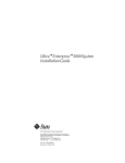
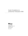
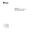
Ultra™ Enterprise™ 6000/5000/4000
Systems Power Cord Installation
RevisiontoPowerCordInstallation
Note – This replaces Chapter 2, “Cabling the System,” in the Ultra Enterprise
6000/5000/4000 Systems Installation Guide (part number 802-3844) that is in your
binder.
Information in this document supersedes information in the previously
released manual.
Sun Microsystems Computer Company
A Sun Microsystems, Inc. Business
2550 Garcia Avenue
Mountain View, CA 94043 USA
415 960-1300
fax 415 969-9131
Part No.: 805-1026-10
Revision A, February 1997
Copyright 1997 Sun Microsystems, Inc. 2550 Garcia Avenue, Mountain View, California 94043-1100 U.S.A. All right reserved.
This product or document is protected by copyright and distributed under licenses restricting its use, copying, distribution, and decompilation.
No part of this product or document may be reproduced in any form by any means without prior written authorization of Sun and its licensors,
if any.
Portions of this product may be derived from the UNIX® system, licensed from Novell, Inc., and from the Berkeley 4.3 BSD system, licensed from
the University of California. UNIX is a registered trademark in the United States and in other countries and is exclusively licensed by X/Open
Company Ltd. Third-party software, including font technology in this product, is protected by copyright and licensed from Sun’s suppliers.
RESTRICTED RIGHTS: Use, duplication, or disclosure by the U.S. Government is subject to restrictions of FAR 52.227-14(g)(2)(6/87) and
FAR 52.227-19(6/87), or DFAR 252.227-7015(b)(6/95) and DFAR 227.7202-3(a).
Sun, Sun Microsystems, the Sun logo, and Solaris are trademarks or registered trademarks of Sun Microsystems, Inc. in the United States and in
other countries. All SPARC trademarks are used under license and are trademarks or registered trademarks of SPARC International, Inc. in the
United States and in other countries. Products bearing SPARC trademarks are based upon an architecture developed by Sun Microsystems, Inc.
The OPEN LOOK® and Sun™ Graphical User Interfaces were developed by Sun Microsystems, Inc. for its users and licensees. Sun
acknowledges the pioneering efforts of Xerox Corporation in researching and developing the concept of visual or graphical user interfaces for the
computer industry. Sun holds a nonexclusive license from Xerox to the Xerox Graphical User Interface, which license also covers Sun’s licensees
who implement OPEN LOOK GUIs and otherwise comply with Sun’s written license agreements.
THIS PUBLICATION IS PROVIDED “AS IS” WITHOUT WARRANTY OF ANY KIND, EITHER EXPRESS OR IMPLIED, INCLUDING,
BUT NOT LIMITED TO, THE IMPLIED WARRANTIES OF MERCHANTABILITY, FITNESS FOR A PARTICULAR PURPOSE, OR
NON-INFRINGEMENT.
Copyright 1997 Sun Microsystems, Inc., 2550 Garcia Avenue, Mountain View, Californie 94043-1100 U.S.A.
Tous droits réservés. Ce produit ou document est protégé par un copyright et distribué avec des licences qui en restreignent l’utilisation, la copie
et la décompilation. Aucune partie de ce produit ou de sa documentation associée ne peut être reproduite sous aucune forme, par quelque moyen
que ce soit, sans l’autorisation préalable et écrite de Sun et de ses bailleurs de licence, s’il y en a.
Des parties de ce produit pourront être derivées du système UNIX® licencié par Novell, Inc. et du système Berkeley 4.3 BSD licencié par
l’Université de Californie. UNIX est une marque enregistrée aux Etats-Unis et dans d’autres pays, et licenciée exclusivement par X/Open
Company Ltd. Le logiciel détenu par des tiers, et qui comprend la technologie relative aux polices de caractères, est protégé par un copyright et
licencié par des fournisseurs de Sun.
Sun, Sun Microsystems, le logo Sun, et Solaris sont des marques déposées ou enregistrées de Sun Microsystems, Inc. aux Etats-Unis et dans
d’autres pays. Toutes les marques SPARC, utilisées sous licence, sont des marques déposées ou enregistrées de SPARC International, Inc. aux
Etats-Unis et dans d’autres pays. Les produits portant les marques SPARC sont basés sur une architecture développée par Sun Microsystems, Inc.
Les utilisateurs d’interfaces graphiques OPEN LOOK® et Sun™ ont été développés de Sun Microsystems, Inc. pour ses utilisateurs et licenciés.
Sun reconnaît les efforts de pionniers de Xerox Corporation pour la recherche et le développement du concept des interfaces d’utilisation visuelle
ou graphique pour l’industrie de l’informatique. Sun détient une licence non exclusive de Xerox sur l’interface d’utilisation graphique, cette
licence couvrant aussi les licenciés de Sun qui mettent en place les utilisateurs d’interfaces graphiques OPEN LOOK et qui en outre se
conforment aux licences écrites de Sun.
CETTE PUBLICATION EST FOURNIE "EN L’ETAT" SANS GARANTIE D’AUCUNE SORTE, NI EXPRESSE NI IMPLICITE, Y COMPRIS, ET
SANS QUE CETTE LISTE NE SOIT LIMITATIVE, DES GARANTIES CONCERNANT LA VALEUR MARCHANDE, L’APTITUDE DES
PRODUITS A REPONDRE A UNE UTILISATION PARTICULIERE OU LE FAIT QU’ILS NE SOIENT PAS CONTREFAISANTS DE PRODUITS
DE TIERS.
Please
Recycle
2
Cabling the System
This chapter contains procedures for connecting the power cord to the AC
power supply and instructions for cabling the system to the network.
2.1 Preparing the System for Cabling
Make sure the server is in an area that allows access to both the front and rear
of the chassis. This site should conform to site preparation guidelines and
specifications covered in Chapter 1.
2.2 Removing and Replacing the Enterprise 6000/5000 Cabinet Rear Screen and
Kick Panel
Removing the Rear Screen and Kick Panel
1. Locate the plastic key that is in the accessory box.
2. Open the door on the left side of the top bezel to access the key switch.
The door opens when you press on the recessed area.
3. Turn the system key switch to
See Figure 2-1.
(the Standby position).
4. Ensure that the AC power sequencer switch is set to Off.
This switch is at the rear of the cabinet. See Figure 2-2.
2-1
2
Standby position
Figure 2-1
Keyswitch Standby Position
5. If the rear screen is still in place, remove it.
Note – If your system cabinet has a hinged rear door, use the sliding door latch
to open the door, and proceed to Step 6 and Step 7.
a. Remove two screws near the top of the screen.
See Figure 2-2.
b. Tilt the screen out and lift it free of the chassis.
Set the screen aside.
6. Remove the AC power cord that is coiled inside the server cabinet.
Set the power cord aside.
7. Remove the kick panel by loosening the two screws.
See Figure 2-3. Set the panel aside.
2-2
Ultra Enterprise 6000/5000/4000 Systems Installation Guide—February 1997
2
AC
power
sequencer
Figure 2-2
Rear
screen
AC Power Sequencer Power Switch and Rear Screen
Replacing the Rear Screen and Kick Panel
1. Tighten the two screws to secure the kick panel to the cabinet.
If cables are to be routed under the floor, the cables should be between the
bottom panel and the kick panel. See Figure 2-3.
2. Place the bottom of the rear screen on the flanges near the cabinet bottom.
3. Tilt the rear screen against the frame and install two screws to secure the
screen in place.
See Figure 2-2.
4. After all the cables are connected and the screen and panel have been
replaced, power on the system.
Cabling the System
2-3
2
AC connector
Bottom panel
Cable
Kick panel
Figure 2-3
Routing Cables Under the Kick Panel
2.3 Connecting the Power Cords
2.3.1 Connecting the Enterprise 6000/5000 System Power Cord
1. Remove the rear screen and the kick panel.
See Section 2.2, “Removing and Replacing the Enterprise 6000/5000 Cabinet
Rear Screen and Kick Panel.”
2. Connect the power cord to the AC connector.
This connector is at the rear of the cabinet at the bottom-right corner.
a. Open the spring-loaded cover on the AC connector housing.
b. Plug in the power cord female end.
2-4
Ultra Enterprise 6000/5000/4000 Systems Installation Guide—February 1997
2
3. Route the AC power cord and external interface cables along the bottom
panel of the cabinet and over the edge of the bottom panel.
See Figure 2-3. The cables should be between the bottom panel and the kick
panel when you replace the kick panel.
4. Connect the male end of the power cord to a grounded wall outlet.
The outlet must be a 200-240 VAC 30A circuit, dedicated solely to the server
cabinet, as described in the site preparation instructions in Chapter 1.
Warning – Risk of electric shock. Do NOT turn on AC power to the unit yet.
5. Continue with Section 2.4 through Section 2.7 for further cabling
instructions, and then see Section 2.2 to replace the rear screen and kick
panel.
2.3.2 Connecting the Enterprise 4000 System Power Cord
1. Insert the key provided with your system into the front panel key switch.
Turn it to the Standby position (fully counterclockwise).
See Figure 2-4.
Standby
Figure 2-4
Key Switch Positions
2. Turn the AC power switch to Off.
This switch is in the upper left corner of the system rear. See Figure 2-5.
Cabling the System
2-5
2
3. Connect the female end of the power cord into the AC connector.
This connector is to the left of the AC power switch on the system rear.
See Figure 2-5.
4. Connect the male end of the power cord into a grounded wall outlet.
The outlet must be a 100-240 VAC 15A circuit.
AC connector
AC power switch
Figure 2-5
!
AC Power Switch and Power Receptacle
Caution – Do NOT turn on power to the unit yet. Doing so could cause system
damage to occur.
5. Continue with Section 2.4 through Section 2.7 for further cabling
instructions.
6. After all the cables are connected, power on the system.
2.4 Connecting the Network Cable to the System
The locations specified in the following instructions assume the use of twistedpair 10BASE-T or 100BASE-T Ethernet.
1. Locate the network cable.
Figure 2-6 shows the twisted-pair Ethernet network cable.
2-6
Ultra Enterprise 6000/5000/4000 Systems Installation Guide—February 1997
2
Figure 2-6
Network Cable
2. Connect one end of the network cable into the RJ-45 twisted-pair network
port.
For 10/100BASE-T Ethernet, the default interface port is the onboard
connector on the I/O board in slot 1. See Figure 2-7.
Ethernet port
Figure 2-7
10/100BASE-T Ethernet Connection
3. Enterprise 6000/5000 systems only: route the cable down along the right
mounting rail of the chassis.
Use tie wraps to secure the cable to the rail.
Cabling the System
2-7
2
2.5 Connecting the System to the Network
1. Connect the network cable to a twisted-pair-to-transceiver interface box.
2. Connect the interface box with an appropriate cable to a network
transceiver.
Figure 2-8 shows a typical arrangement for connecting the system to an
Ethernet network.
3. For Ethernet cables, determine if the cable has N-type screw-on
connectors at the ends.
• If the Ethernet cable lacks N-type connectors at the ends, use a “vampire”
tap to connect the cable to the transceiver. See Figure 2-8. To connect the
cable to the transceiver, use instructions provided with the vampire tap.
• If the Ethernet cable has N-type connectors, connect the Ethernet cable to
the transceiver:
a. Screw the Ethernet coaxial cable into one of the round screw-on type
connectors on the transceiver.
Use either one of the transceiver connectors.
b. Screw the other Ethernet coaxial cable into the other round screw-on
type connector on the transceiver.
4. Determine if a terminator should be installed. Table 2-1 lists the cabling
limitations for Ethernet.
5. If termination is required, install a 50-ohm terminator in the unused
transceiver N connector or at the end of the coaxial cable. Use a female
double N-type connector.
Figure 2-8 shows the elements used in the installation process.
2-8
Ultra Enterprise 6000/5000/4000 Systems Installation Guide—February 1997
2
Vampire tap or N-type connectors
Ethernet cable
Transceiver
Transceiver drop cable
(coaxial or optical fiber)
Server
Hardware interface
10/100BASE-T
twisted-pair cable
Figure 2-8
Connecting Twisted Pair Ethernet to N-type Coaxial Cable
Table 2-1 lists the cabling limitations for Ethernet.
Table 2-1
Ethernet Cabling Limitations for N-type Coaxial Cable
Cable Segment
Allowed contiguous length of cable segments
Distance between transceivers (multiples-of)
Length in Meters
23.4
70.2
117.0
500.01
2.52
Minimum length of Ethernet coaxial cable segments
23.4
Maximum length of transceiver “drop” cable
50.0
Minimum length of twisted pair cable
no minimum
Maximum length of twisted pair cable
110
1. Finite lengths (as constrained by transmission line phenomena). Minimum length = 23.4M; maximum = 500M.
If cable falls shorter than one of these values, add cable to achieve next-highest value.
2. Transceivers are placed at intervals of 2.5 meters, or multiples of 2.5 meters along the Ethernet cable.
Example: transceivers are connected 2.5 meters apart, not 2.0 meters.
Example: transceivers are connected 15 meters apart (6 multiples of 2.5 meters), not 14.0 meters.
Cabling the System
2-9
2
Figure 2-9 shows an example of a typical network setup. The Ultra Enterprise
6000/5000/4000 systems can be any server shown in this figure.
Transceiver
5 Meters
Transceiver
15 Meters
Transceiver
3.4 Meter
Extension
Transceiver drop cable
Twisted pair cable
Server or workstation
Terminator
Server or workstation
Server or workstation
Note: 5 Meters + 15 Meters + 3.4 Meter Extension = 23.4 Meters minimum length allowed.
Figure 2-9
Ethernet Cabling Length — Example Using N-type Cable
Note – Sun equipment conforms to the Ethernet 10/100BASE-T standard,
which states that the 10/100BASE-T Link Integrity Test function should always
be enabled on both the host and the hub. If you have problems verifying
connection between Sun equipment and your hub, verify that your hub also
has the link test function enabled. See Section 3.4, “Failure of Network
Communications,” and refer to the manual provided with your hub for more
information about the Link Integrity Test function.
2.6 Connecting an ASCII Terminal
An ASCII terminal (or workstation) must be attached to the server to display
diagnostic messages produced by the firmware (power-on self test/POST or
OpenBoot PROM/OBP) program. A terminal is not required for normal server
operations, so it may be necessary to locate a terminal to connect to the server.
1. Connect the terminal cable into serial port A on the clock board.
See Figure 2-10.
2-10
Ultra Enterprise 6000/5000/4000 Systems Installation Guide—February 1997
2
Serial port A
Figure 2-10 Clock Board
2. Enterprise 6000/5000 systems only: route the terminal cable from the clock
board down along the right mounting rail of the cabinet.
Use tie wraps to secure the terminal cable to the mounting rail.
3. Connect the terminal power cord into an AC wall outlet.
4. Configure the ASCII terminal as follows:
• 9600 bps
• 1 stop bit
• 8 data bits
• Parity off
• Full duplex
Refer to the instruction manual shipped with the terminal for specific
configuration instructions.
Note – The setup parameters listed in Step 4 may differ from the setup at the
customer site. These parameters can be changed in the NVRAM. Refer to the
set-defaults and printenv commands in the OpenBoot Command Reference
manual, part number 802-3242.
Cabling the System
2-11
2
2.7 Connecting the Fiber Cable to the I/O Board
1. Remove the two plastic caps that cover the cable connector on the FC/OM
module.
2. Remove the plastic cap covering the ends of the fiber cable.
3. Connect one end of the fiber cable into the FC/OM module installed on
the I/O board.
Align the notch in the cable connector with the key notch in the module
connector. See Figure 2-11.
4. Connect the other end of the fiber cable into the FC/OM connector on the
SPARCstorage Array (or other storage device with fiber optics interface)
rear panel.
Align the notch in the cable connector with the notch in the connector on the
storage device rear panel.
Notch on
fiber cable
Fibre card connector
er
Fib 1
Key notch
in module
connector
er
Fib 0
A
B
Connect cable through
Port A (Fiber 0) or
Port B (Fiber 1)
Figure 2-11 Fiber Cable and Fibre Card Connectors and Ports on the I/O Board
2-12
Ultra Enterprise 6000/5000/4000 Systems Installation Guide—February 1997
2
2.8 Connecting External SCSI Devices
External SCSI-2 devices connect to your system through the built-in singleended Fast/Wide SCSI-2 port on I/O boards (except for the board in slot 1), or
through FSBE/S, DSBE/S, SWIS/S, or DWIS/S SBus cards installed on I/O
boards.
Note – The onboard SCSI-2 bus on the I/O board in slot 1 controls internal
SCSI tray devices. Therefore, the external SCSI connector on the I/O board in
slot 1 must always have a terminator installed.
Note – The maximum combined length for a string of SCSI cables is six meters
for non-differential cables. For differential SCSI cables, the maximum is 25
meters.
When calculating the total length of a SCSI string, include external cables,
internal cables, and printed traces. Table 2-2 lists internal measurements for the
Enterprise servers.
Table 2-2
Internal SCSI Lengths (Approximate)
Location
Internal Length
Comments
Enterprise 6000 slot 1
3.7 meters
Includes I/O board traces and cables to SCSI tray
Enterprise 5000 slot 1
3.7 meters
Includes I/O board traces and cables to SCSI tray
Enterprise 4000 slot 1
1.4 meters
Includes I/O board traces and cables to SCSI tray
SBus I/O board
0.43 meter
Includes board traces only
Graphics I/O board
0.43 meter
Includes board traces only
Disk board
0.64 meter
Includes board traces only
For information on device addressing, priorities, and slot assignments, refer to
Appendix D, “Rules for System Configuration” in the Ultra Enterprise
6000/5000/4000 Systems Manual, part number 802-3845.
!
Caution – Risk of equipment damage. Do not assign the same SCSI address to
two devices sharing the same SCSI bus or SBus card.
Cabling the System
2-13
2
To connect an external SCSI device to your system:
1. Connect a SCSI cable to the appropriate SCSI-2 host on the I/O board.
• For the I/O board in slot 1, this is an SBus card installed in an appropriate
SBus slot.
• For I/O boards in slots 2 through 15, use the onboard SCSI-2 port or an
SBus card installed in an appropriate SBus slot.
Figure 2-12 shows the location of the onboard single-ended SCSI connector
on the I/O board.
Fast/wide onboard SCSI-2,
68-pin connector
Figure 2-12 Onboard Single-ended SCSI Connector on the I/O Board
2. Enterprise 6000/5000 systems only: route the cable from the I/O board
down along the left mounting rail inside the cabinet.
Use tie wraps to secure the cable to the left mounting rail.
3. Connect the other end of the SCSI cable to the external SCSI-2 device.
4. Enterprise 6000/5000 systems only: return to Section 2.2, “Removing and
Replacing the Enterprise 6000/5000 Cabinet Rear Screen and Kick Panel”
to replace the screen and panel. Then power on and test the server.
This concludes the hardware installation for the standalone server. You can
now power on the system and test the server.
2-14
Ultra Enterprise 6000/5000/4000 Systems Installation Guide—February 1997