1
Sun UltraTM 45 and Ultra 25
Workstations Service and
Diagnostics Manual
Sun Microsystems, Inc.
www.sun.com
Part No. 819-1892-12
May 2006, Revision A
Submit comments about this document at: http://www.sun.com/hwdocs/feedback
Copyright 2006 Sun Microsystems, Inc., 4150 Network Circle, Santa Clara, California 95054, U.S.A. All rights reserved.
Sun Microsystems, Inc. has intellectual property rights relating to technology that is described in this document. In particular, and without
limitation, these intellectual property rights may include one or more of the U.S. patents listed at http://www.sun.com/patents and one or
more additional patents or pending patent applications in the U.S. and in other countries.
This document and the product to which it pertains are distributed under licenses restricting their use, copying, distribution, and
decompilation. No part of the product or of this document may be reproduced in any form by any means without prior written authorization of
Sun and its licensors, if any.
Third-party software, including font technology, is copyrighted and licensed from Sun suppliers.
Parts of the product may be derived from Berkeley BSD systems, licensed from the University of California. UNIX is a registered trademark in
the U.S. and in other countries, exclusively licensed through X/Open Company, Ltd.
Sun, Sun Microsystems, the Sun logo, docs.sun.com, Sun Blade, SunVTS, SunSolve, SunPCi, Java, OpenBoot, StorEdge, Ultra, and Solaris are
trademarks or registered trademarks of Sun Microsystems, Inc. in the U.S. and in other countries.
All SPARC trademarks are used under license and are trademarks or registered trademarks of SPARC International, Inc. in the U.S. and in other
countries. Products bearing SPARC trademarks are based upon an architecture developed by Sun Microsystems, Inc. The Energy Star logo is a
registered trademark of the EPA.
The OPEN LOOK and Sun™ Graphical User Interface was developed by Sun Microsystems, Inc. for its users and licensees. Sun acknowledges
the pioneering efforts of Xerox in researching and developing the concept of visual or graphical user interfaces for the computer industry. Sun
holds a non-exclusive license from Xerox to the Xerox Graphical User Interface, which license also covers Sun’s licensees who implement OPEN
LOOK GUIs and otherwise comply with Sun’s written license agreements.
Sun Microsystems is an ENERGY STAR partner. Those configurations of this product
that bear the ENERGY STAR mark meet or exceed the ENERGY STAR guidelines.
ENERGY STAR
U.S. Government Rights – Commercial use. Government users are subject to the Sun Microsystems, Inc. standard license agreement and
applicable provisions of the FAR and its supplements.
DOCUMENTATION IS PROVIDED "AS IS" AND ALL EXPRESS OR IMPLIED CONDITIONS, REPRESENTATIONS AND WARRANTIES,
INCLUDING ANY IMPLIED WARRANTY OF MERCHANTABILITY, FITNESS FOR A PARTICULAR PURPOSE OR NON-INFRINGEMENT,
ARE DISCLAIMED, EXCEPT TO THE EXTENT THAT SUCH DISCLAIMERS ARE HELD TO BE LEGALLY INVALID.
Copyright 2006 Sun Microsystems, Inc., 4150 Network Circle, Santa Clara, Californie 95054, Etats-Unis. Tous droits réservés.
Sun Microsystems, Inc. a les droits de propriété intellectuels relatants à la technologie qui est décrit dans ce document. En particulier, et sans la
limitation, ces droits de propriété intellectuels peuvent inclure un ou plus des brevets américains énumérés à http://www.sun.com/patents et
un ou les brevets plus supplémentaires ou les applications de brevet en attente dans les Etats-Unis et dans les autres pays.
Ce produit ou document est protégé par un copyright et distribué avec des licences qui en restreignent l’utilisation, la copie, la distribution, et la
décompilation. Aucune partie de ce produit ou document ne peut être reproduite sous aucune forme, par quelque moyen que ce soit, sans
l’autorisation préalable et écrite de Sun et de ses bailleurs de licence, s’il y en a.
Le logiciel détenu par des tiers, et qui comprend la technologie relative aux polices de caractères, est protégé par un copyright et licencié par des
fournisseurs de Sun.
Des parties de ce produit pourront être dérivées des systèmes Berkeley BSD licenciés par l’Université de Californie. UNIX est une marque
déposée aux Etats-Unis et dans d’autres pays et licenciée exclusivement par X/Open Company, Ltd.
Sun, Sun Microsystems, le logo Sun, docs.sun.com, Sun Blade, SunVTS, SunSolve, SunPCi, Java, OpenBoot, StorEdge, Ultra, et Solaris sont des
marques de fabrique ou des marques déposées de Sun Microsystems, Inc. aux Etats-Unis et dans d’autres pays.
Toutes les marques SPARC sont utilisées sous licence et sont des marques de fabrique ou des marques déposées de SPARC International, Inc.
aux Etats-Unis et dans d’autres pays. Les produits portant les marques SPARC sont basés sur une architecture développée par Sun
Microsystems, Inc.
L’interface d’utilisation graphique OPEN LOOK et Sun™ a été développée par Sun Microsystems, Inc. pour ses utilisateurs et licenciés. Sun
reconnaît les efforts de pionniers de Xerox pour la recherche et le développement du concept des interfaces d’utilisation visuelle ou graphique
pour l’industrie de l’informatique. Sun détient une license non exclusive de Xerox sur l’interface d’utilisation graphique Xerox, cette licence
couvrant également les licenciées de Sun qui mettent en place l’interface d ’utilisation graphique OPEN LOOK et qui en outre se conforment
aux licences écrites de Sun.
LA DOCUMENTATION EST FOURNIE "EN L’ÉTAT" ET TOUTES AUTRES CONDITIONS, DECLARATIONS ET GARANTIES EXPRESSES
OU TACITES SONT FORMELLEMENT EXCLUES, DANS LA MESURE AUTORISEE PAR LA LOI APPLICABLE, Y COMPRIS NOTAMMENT
TOUTE GARANTIE IMPLICITE RELATIVE A LA QUALITE MARCHANDE, A L’APTITUDE A UNE UTILISATION PARTICULIERE OU A
L’ABSENCE DE CONTREFAÇON.
Contents
Preface
1.
2.
xv
Product Description
1.1
Product Overview
1.2
External System Description
1.3
Supported Sun Monitors
1–1
1–3
1–6
Preparing to Replace Components
2.1
Safety Information
2–1
2–1
2.1.1
Safety Precautions
2.1.2
Safety Symbols
2.1.3
Electrostatic Discharge Safety
2–1
2–2
2.2
Required Tools
2.3
Powering Off the Workstation
2.3.1
2.4
3.
1–1
2–2
2–3
2–4
Opening the Workstation
2–6
Finding Replacement Procedures
2–7
Replacing the Motherboard and Associated Components
3.1
Motherboard Connector Overview
3.2
Replacing the DIMMs
3.2.1
3–1
3–2
3–3
DIMM Configuration Rules
3–4
iii
3.3
3.4
3.5
3.2.2
OpenBoot PROM Memory Message
3.2.3
Removing the DIMMs
3.2.4
Installing the DIMMs
Replacing the Battery
4.
4.2
iv
3–9
Removing the Battery
3.3.2
Installing the Battery
Replacing the NVRAM
3–10
3–11
3–11
3.4.1
Removing the NVRAM
3.4.2
Installing the NVRAM
Replacing the PCI Cards
3–11
3–12
3–13
3.5.1
Identifying the PCI Cards
3.5.2
Removing a PCI Card
3.5.3
General PCI Card Guidelines
3.5.4
Installation Considerations for Graphics Accelerators
3–13
3–14
3–15
3.5.4.1
Default Console Display
3.5.4.2
Changing the Console Display
Installing a PCI Card
Replacing the Motherboard
3–16
3–16
3–18
3–20
3.6.1
Removing the Motherboard
3.6.2
Installing the Motherboard
Replacing Storage Devices
4.1
3–7
3–8
3.3.1
3.5.5
3.6
3–6
3–20
3–23
4–1
Replacing a Hard Drive
4–2
4.1.1
Removing a Hard Drive
4.1.2
Installing a Hard Drive
4–2
4–3
Replacing the Hard Drive Backplane and Cables
4–4
4.2.1
Removing the Hard Drive Backplane and Cables
4.2.2
Installing the Hard Drive Backplane and Cables
Sun Ultra 45 and Ultra 25 Workstations Service and Diagnostics Manual • May 2006
4–4
4–6
3–16
4.3
5.
5.2
7.
4.3.1
Removing the I/O Module and DVD-Dual Drive
4.3.2
Installing the I/O Module and DVD-Dual Drive
Replacing Chassis Components
5.1
6.
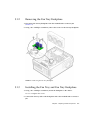
Replacing the I/O Module With the DVD-Dual Drive and Audio USB
Board 4–6
Replacing the Fan Tray and Fan Tray Backplane
Removing the Fan Tray
5.1.2
Removing the Fan Tray Backplane
5.1.3
Installing the Fan Tray and Fan Tray Backplane
Replacing the Power Supply
5–2
5–3
5–3
5–4
5.2.1
Removing the Power Supply
5.2.2
Installing the Power Supply
6–1
6.1
Reassembling the Workstation
6–1
6.2
Verifying Component Installation
5–4
5–6
6–5
6.2.1
Reconfiguring the System With boot -r Option
6.2.2
Verifying Configuration With POST
6.2.3
Verifying Configuration With POST and OpenBoot Diagnostics
6–5
6.2.4
Verifying Configuration With prtdiag
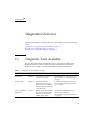
Diagnostics Overview
Diagnostic Tools Available
7.2
Diagnostic Tests
6–5
6–5
7–1
7–2
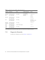
Diagnostics Hierarchy
Power-On Sequence
Basic Diagnostics
6–5
7–1
7.1
8.1
5–1
5.1.1
7.2.1
8.
4–8
5–1
Finishing Component Replacement
7.3
4–6
7–4
7–6
8–1
LED Diagnostics
8–1
Contents
v
9.
8.2
Audio Diagnostics
8.3
Display Diagnostics
8–2
Solaris 10 Predictive Self-Healing and Solaris Diagnostics
9.1
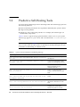
Predictive Self-Healing Overview
9.2
Predictive Self-Healing Tools
9.3
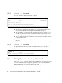
Using the Predictive Self-Healing Commands
9.3.1
9.3.2
9.3.3
9–1
9–2
Using the fmdump Command
9–3
9–3
9.3.1.1
fmdump -V Command
9–4
9.3.1.2
fmdump -e Command
9–4
Using the fmadm faulty Command
9–4
9.3.2.1
9–5
fmadm config Command
Using the fmstat Command
9–5
9.4
Determining Which Diagnostics Tools to Use
9.5
Traditional Solaris Troubleshooting Commands
9.5.1
9.5.2
iostat Command
9–7
9.5.1.1
9–7
9.5.3
9.5.5.1
9.5.6
9–8
9–9
9–10
Options
9–11
9–11
9–12
Options
ps Command
9.5.6.1
9.5.7
Options
ping Command
9–6
9–8
netstat Command
9.5.4.1
9.5.5
Options
prtconf Command
9.5.3.1
9.5.4
Options
prtdiag Command
9.5.2.1
vi
8–2
9–12
9–13
Options
9–14
prstat Command
9–15
9.5.7.1
9–15
Options
Sun Ultra 45 and Ultra 25 Workstations Service and Diagnostics Manual • May 2006
9–6
9–1
10.
11.
NVRAM
10–1
10.1
Obtaining the ok Prompt
10–2
10.2
Changing NVRAM Configuration Parameter Values
10–3
10.2.1
Displaying and Changing Parameter Values
10–3
10.2.2
Configuration Parameter Default Values
10.3
Setting NVRAM Security Mode
10.4
eeprom Command
10.5
Key Commands
11.3
11.4
10–9
10–9
Stop-A Key Sequence
10.5.2
Stop-N Equivalent Key Sequence Procedure
10–10
10–10
10.5.2.1
Resetting the NVRAM Temporarily
10–10
10.5.2.2
Resetting the NVRAM Permanently
10–12
10.5.2.3
Workstation Power Cycling
11–1
Configuring POST Output
post Command
11–1
11–2
11.2.1
Diagnostic Levels
11–3
11.2.2
Output Verbosity
11–3
POST Output
10–12
11–1
POST Overview
11.1.1
11.2
10–7
10.5.1
Power-On Self-Test
11.1
10–5
11–4
11.3.1
post min normal
11.3.2
post max max
11–5
11.3.3
post min min
11–13
11.3.4
post max min
11–13
Analyzing POST Messages
11.4.1
Error Messages
11.4.2
Warning Messages
11.4.3
Info Messages
11–4
11–14
11–14
11–15
11–16
Contents
vii
11.5
Setting Up for POST
11.5.1
12.
11–16
11.5.1.1
OpenBoot PROM Level Procedure
11.5.1.2
Solaris OS Level Procedure
11–17
11–17
Obtaining the ok Prompt
11.5.3
Configuring an External Display Device
11–17
11.5.3.1
Configuring a Serial Terminal
11–17
11.5.3.2
Configuring a Second System
11–18
11.5.3.3
Making a Tip Connection
11.5.3.4
Managing Tip Connections
Running POST
11–17
11–19
11–19
11–20
Disabling Diagnostics and Auto Boot
11–20
11.6.0.1
OpenBoot PROM Level Procedure
11.6.0.2
Solaris OS Level Procedure
OpenBoot PROM
11–21
12–1
12.1
OpenBoot PROM Overview
12.2
OpenBoot PROM Utilities
12.3
viii
Verifying the Baud Rate
11.5.2
11.5.4
11.6
11–16
12–1
12–2
12.2.1
show-devs Utility
12–2
12.2.2
watch-net Utility
12–3
12.2.3
probe-scsi Utility
12.2.4
probe-ide Utility
12.2.5
banner Utility
12.2.6
watch-clock Utility
12.2.7
date Utility
12.2.8
.version Utility
OpenBoot Diagnostics
12–3
12–4
12–4
12–5
12–5
12–5
12–6
12.3.1
Starting OpenBoot Diagnostics
12.3.2
obdiag Menu
12–6
12–7
Sun Ultra 45 and Ultra 25 Workstations Service and Diagnostics Manual • May 2006
11–20
12.3.2.1
12.4
13.
Interpreting OpenBoot Diagnostics Tests
12.3.3
Configuring OpenBoot Diagnostics
12.3.4
Initiating a Test
12.3.5
Test Output
12–9
12–11
13–1
13.1
SunVTS Overview
13–1
13.2
Installing SunVTS
13–1
13.3
SunVTS Documentation
A. Power Management
13–2
A–1
A.1
Power Management Overview
A.2
Using Dtpower
A.3
Modifying Power Management
A.3.1
A–1
A–2
A–3
Activating the Workstation From Low-Power Mode
B. Product Specifications
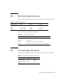
Physical Specifications
B.2
Electrical Specifications
B–3
B.3
Acoustic Specifications
B–3
B.4
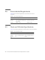
Environmental Requirements
B.5
Shock and Vibration Specifications
C. Functional Description
B–1
B–4
B–4
C–1
Hardware Architecture
C–1
C.1.1
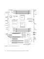
Motherboard Layout Diagram
C.1.2
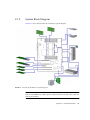
System Block Diagram
C–3
C.1.3
Component Overview
C–4
C.1.3.1
A–3
B–1
B.1
C.1
12–8
12–9
OpenBoot PROM Messages
SunVTS
12–8
CPU
C–1
C–4
Contents
ix
C.2
C.3
x
Memory Subsystem
C.1.3.3
I/O Bridge Chip
C.1.3.4
I/O Subsystem
C.1.3.5
Gigabit Ethernet
Motherboard
C–4
C–5
C–5
Motherboard Block Diagram
C.2.2
CPU Description
C.2.3
Memory Controller
Serial Ports
C–4
C–4
C.2.1
C–5
C–6
C–7
C–8
C.3.1
Configuring for an Alternate Break Key Sequence on the Server
C–8
C.3.2
Filtering the Tip Connection Through a Network Terminal
Concentrator C–8
C.3.3
Disabling the Keyboard Abort on the Server
C.3.4
Disabling the Tip Connection on the Server
C.3.5
Permanently Disabling the Keyboard Abort or Configuring an
Alternate Break Key Sequence on the Server C–10
Glossary
Index
C.1.3.2
Glossary–1
Index–1
Sun Ultra 45 and Ultra 25 Workstations Service and Diagnostics Manual • May 2006
C–9
C–9
Figures
FIGURE 1-1
Monitor, Keyboard, Mouse, and Sun Ultra 45 or Ultra 25 Workstation
FIGURE 1-2
Front Panel Overview
1–4
FIGURE 1-3
Rear Panel Overview
1–5
FIGURE 2-1
Required Tools
FIGURE 2-2
Power Button and Sleep Key Location
2–5
FIGURE 2-3
Disconnecting the Workstation Cables
2–5
FIGURE 2-4
Removing the Side Cover and Access Panel
FIGURE 2-5
Major Workstation Components
FIGURE 3-1
Motherboard With Component Connections
FIGURE 3-2
Motherboard Cables and Cable Clips
FIGURE 3-3
DIMM Configurations for Single-CPU Workstations
FIGURE 3-4
DIMM Configurations for Ultra 45 Dual-CPU Workstations
FIGURE 3-5
Releasing the DIMM
FIGURE 3-6
Removing and Installing the Battery
FIGURE 3-7
Removing and Installing the NVRAM
3–12
FIGURE 3-8
PCI Card Location and Identification
3–14
FIGURE 3-9
Removing the PCI Card
FIGURE 3-10
Installing a PCI Card
FIGURE 3-11
Removing Components from the Motherboard
FIGURE 3-12
Disconnecting Motherboard Cables
1–3
2–3
2–7
2–8
3–2
3–3
3–4
3–5
3–7
3–10
3–15
3–18
3–21
3–22
xi
FIGURE 3-13
Releasing the Motherboard Latch
FIGURE 3-14
Reconnecting Cables to the Motherboard
FIGURE 3-15
Installing the Motherboard and Related Components
FIGURE 4-1
Removing the Hard Drive 4–3
FIGURE 4-2
Disconnecting the Cables From the Hard Drive Backplane
FIGURE 4-3
Removing the I/O Module With the DVD-Dual Drive and Audio USB Board
FIGURE 4-4
Securing the Audio USB Cables in the I/O Cable Clip
FIGURE 5-1
Removing the Fan Tray
FIGURE 5-2
Removing the Fan Tray Backplane
FIGURE 5-3
Removing the Power Supply
FIGURE 5-4
Installing the Power Supply
FIGURE 5-5
Power Supply Cable Connections at Motherboard and Hard Drive Backplane
FIGURE 6-1
Reassembling the Workstation
FIGURE 6-2
Reconnecting the Cables
FIGURE 6-3
Powering On the Workstation
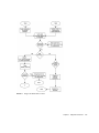
FIGURE 7-1
Diagnostic Method Flow Chart
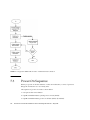
FIGURE 7-2
Diagnostics Method Flow Chart – Traditional Data Collection
FIGURE 10-1
NVRAM on Motherboard
FIGURE 11-1
Crossover Cable Wiring Diagram
FIGURE B-1
Workstation Dimensions With Stabilizer Open
FIGURE B-2
Workstation Dimensions Without Stabilizer
FIGURE C-1
Sun Ultra 45 Motherboard Diagram
FIGURE C-2
Sun Ultra 45 Workstation System Diagram
FIGURE C-3
Sun Ultra 45 Motherboard Block Diagram
FIGURE C-4
UltraSPARC IIIi Chip Architecture
xii
3–23
3–25
3–27
4–5
4–7
4–9
5–2
5–3
5–5
5–7
6–2
6–3
6–4
7–5
7–6
10–1
11–19
B–2
B–2
C–2
C–3
C–6
C–7
Sun Ultra 45 and Ultra 25 Workstations Service and Diagnostics Manual • May 2006
5–8
Tables
TABLE 1-1
Sun Ultra 45 and Ultra 25 Workstations Features
1–1
TABLE 1-2
Front Panel Overview, Sun Ultra 45 and Ultra 25 Workstations
TABLE 1-3
Rear Panel Overview, Sun Ultra 45 and Ultra 25 workstations
TABLE 1-4
Monitors supported by the Sun Ultra 45 and Ultra 25Workstations
TABLE 2-1
Sun Ultra 45 or Ultra 25 Workstation Replaceable Components
TABLE 3-1
OpenBoot PROM Memory Checks and Actions
TABLE 3-2
Battery Specifications
3–9
TABLE 3-3
PCI Card Probe Order
3–16
TABLE 4-1
Hard Drive Specifications 4–2
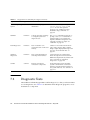
TABLE 7-1
Diagnostic Tools Sorted by Tool Type
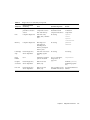
TABLE 7-2
Diagnostics Tools Sorted by Component
TABLE 8-1
Front Panel LED States
TABLE 8-2
Twisted-Pair Ethernet LED Status
TABLE 9-1
System Generated Predictive Self-Healing Message
TABLE 9-2
Options for iostat
TABLE 9-3
Options for prtdiag
9–8
TABLE 9-4
Options for prtconf
9–10
TABLE 9-5
Options for netstat
9–11
TABLE 9-6
Options for ping
TABLE 9-7
Options for ps
1–4
1–5
1–6
2–9
3–6
7–1
7–3
8–1
8–1
9–2
9–7
9–12
9–14
xiii
TABLE 9-8
Options for prstat
TABLE 10-1
Methods for Obtaining the ok Prompt 10–2
TABLE 10-2
NVRAM Parameter Configuration Commands
TABLE 10-3
NVRAM Configuration Parameter Default Values
TABLE 10-4
security-mode Values and Their Enforcement Policy
TABLE 10-5
Stop-N Equivalent Configuration Parameters
TABLE 11-1
POST Diagnostic Levels
TABLE 11-2
POST Output Verbosity
TABLE 11-3
Tests Performed at min and max Diagnostic Levels 11–3
TABLE 11-4
Output Seen at min, normal, and max Output Verbosity 11–3
TABLE 11-5
post min normal Output Comparison
TABLE 11-6
post max max Output Comparison
TABLE 11-7
Serial Terminal Communication Parameters
TABLE 12-1
OpenBoot Diagnostics Test Usage
TABLE 12-2
OpenBoot PROM Messages and Their Meaning
TABLE A-1
Dtpower Power Management Modes
TABLE B-1
Exterior Dimensions B–1
TABLE B-2
Electrical Specifications
TABLE B-3
Power Supply Specifications
TABLE B-4
Declared Noise Emissions: ISO 9296
TABLE B-5
Environmental Requirements
TABLE B-6
Shock and Vibration Values
TABLE C-1
Twisted-Pair Ethernet LED Status
xiv
9–15
10–3
10–5
10–7
10–11
11–2
11–2
11–4
11–5
11–18
12–8
12–11
A–2
B–3
B–3
B–3
B–4
B–4
C–5
Sun Ultra 45 and Ultra 25 Workstations Service and Diagnostics Manual • May 2006
Preface
Use the Sun Ultra 45 and Ultra 25 Workstations Service and Diagnostics Manual to
replace Sun Ultra™ 45 or Ultra 25 workstation components and diagnose
workstation problems.
This document is written for technicians, service personnel, and system
administrators who service and repair computer systems.
To safely and successfully perform diagnostics on the Sun Ultra 45 and Ultra 25
workstations, you should be able to:
■
■
■
Understand the Solaris™ Operating System and the command-line interface.
Obtain superuser privileges for the workstation being serviced.
Understand typical hardware troubleshooting tasks.
If you are not comfortable performing any of the procedures described in this
document, contact your Sun service representative.
How This Document Is Organized
Chapter 1 provides a product description of the Sun Ultra 45 and Ultra 25
workstations.
Chapter 2 provides preliminary steps necessary to prepare for component
replacement.
Chapter 3 provides replacement procedures for components found on the
motherboard.
Chapter 4 provides replacement procedures for data storage components.
Chapter 5 provides replacement procedures for chassis components.
xv
Chapter 6 provides procedures to finish component replacement.
Chapter 7 provides an overview of diagnostics tools and procedures.
Chapter 8 provides basic troubleshooting tasks, commands, and system responses.
Chapter 9 provides details on Solaris predictive self-healing diagnostics tools as well
as other Solaris diagnostics tools.
Chapter 10 provides information about NVRAM and changing NVRAM settings.
Chapter 11 provides diagnostics information related to power-on self-test (POST),
Chapter 11 describes OpenBoot™ Diagnostics for the Sun Ultra 45 and Ultra 25
workstations.
Chapter 12 describes the OpenBoot PROM and related tools.
Chapter 13 provides basic SunVTS™ software information and references to SunVTS
documentation.
Appendix A describes how to manage power-saving modes of the Sun Ultra 45 or
Ultra 25 workstations.
Appendix B lists the specifications of the Sun Ultra 45 and Ultra 25 workstations.
Appendix C provides a functional description of the Sun Ultra 45 and Ultra 25
workstations.
Using UNIX Commands
This document might not contain information about basic UNIX® commands and
procedures such as shutting down the system, booting the system, and configuring
devices. Refer to the following for this information:
■
■
Software documentation that you received with your system
Solaris Operating System documentation, which is at:
http://docs.sun.com
xvi Sun Ultra 45 and Ultra 25 Workstations Service and Diagnostics Manual • May 2006
Shell Prompts
Shell
Prompt
C shell
machine-name%
C shell superuser
machine-name#
Bourne shell and Korn shell
$
Bourne shell and Korn shell superuser
#
Typographic Conventions
Typeface*
Meaning
Examples
AaBbCc123
The names of commands, files,
and directories; on-screen
computer output
Edit your.login file.
Use ls -a to list all files.
% You have mail.
AaBbCc123
What you type, when contrasted
with on-screen computer output
% su
Password:
AaBbCc123
Document titles, new words or
terms, words to be emphasized.
Replace command-line variables
with real names or values.
Read Chapter 6 in the User’s Guide.
These are called class options.
You must be superuser to do this.
To delete a file, type rm filename.
* The settings on your browser might differ from these settings.
Preface
xvii
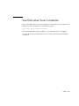
Additional Support Resources
TABLE P-1 lists additional resources to assist with your Sun Ultra 45 or Ultra 25
workstation.
TABLE P-1
Additional Support Resources
Sun Ultra 45 and Ultra 25 Support Resources
URL or Telephone Number
Find Solaris and other software documents here.
This is also an alternative web site for some Sun
Ultra 45 and Ultra 25 documents. This web site
has full search capabilities.
http://docs.sun.com
Warranty and Contract Support contacts. Links to
other service tools.
http://www.sun.com/service/online/
Discussion and Troubleshooting Forums.
http://supportforum.sun.com
Support, Diagnostic Tools, Alerts, for all Sun
products.
http://www.sun.com/bigadmin/
SunSolvesm: Contains links to software patches.
Lists some workstation specifications,
troubleshooting and maintenance information,
and other tools.
http://www.sunsolve.sun.com/handbook_pub/
Lists warranties for every Sun product.
http://www.sun.com/service/support/warranty/
Sun Service Support phone number.
1-800-872-4786 (1-800-USA-4Sun) Select Option 1
This web site lists international telephone
numbers for Sun Service Support.
http://www.sun.com/service/contacting/index.ht
ml
Note – Access to some Sun proprietary information is restricted to authorized Sun
personnel.
Some low-level hardware and software failures require troubleshooting techniques
that are beyond the scope of this document, and are best resolved by those persons
with experience and skill in fault analysis. Your Sun Microsystems service
representative can provide these types of services.
xviii
Sun Ultra 45 and Ultra 25 Workstations Service and Diagnostics Manual • May 2006
Documentation, Support, and Training
Sun Function
URL
Documentation
http://www.sun.com/documentation/
Support
http://www.sun.com/support/
Training
http://www.sun.com/training/
Third-Party Web Sites
Sun is not responsible for the availability of third-party web sites mentioned in this
document. Sun does not endorse and is not responsible or liable for any content,
advertising, products, or other materials that are available on or through such sites
or resources. Sun will not be responsible or liable for any actual or alleged damage
or loss caused by or in connection with the use of or reliance on any such content,
goods, or services that are available on or through such sites or resources.
Preface
xix
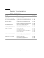
Related Documentation
TABLE P-2
Related Documentation
Application
Title
Part Number
Basic workstation hardware and
software setup
Sun Ultra 45 and Ultra 25 Workstations Installation Guide
(Available in ten languages.)
819-1891
Recent information and changes
Sun Ultra 45 and Ultra 25 Workstations Product Notes
819-1893
Basic workstation setup information
Sun Ultra 45 and Ultra 25 Workstations Getting Started
Guide
819-1894
Safety and compliance
Sun Ultra 45 and Ultra 25 Workstations Safety and
Compliance Guide
819-2785
Important Safety Information for Sun Hardware Systems
816-7190
Solaris 10 1/06 Sun Hardware Platform Guide
817-6337
Solaris 10 System Administration Guide
817-1895
Power Management and Dtpower
Solaris Common Desktop Environment: User’s Guide
806-4743
SunVTS documentation
SunVTS 6.1 User’s Guide
819-2361
SunVTS Quick Reference Card
819-2365
SunVTS Test Reference Manual for SPARC Platforms
819-2362
SunVTS 6.1 Release Notes
819-2363
Sun XVR-100 Graphics Accelerator Installation Guide
816-7560
Sun XVR-2500 Graphics Accelerator Installation and
User’s Guide
817-7517
SunPCi III 3.2.1 User’s Guide
817-3630
Sun PCi III Quick Start Installation Guide
817-4343
SunPCi III 3.2.2 Product Notes
817-3631
Solaris 10 Operating System
Graphics accelerator documentation
SunPCi™ III co-processor board
documentation
xx
Sun Ultra 45 and Ultra 25 Workstations Service and Diagnostics Manual • May 2006
Sun Welcomes Your Comments
Sun is interested in improving its documentation and welcomes your comments and
suggestions. You can submit your comments by going to:
http://www.sun.com/hwdocs/feedback
Please include the title and part number of your document with your feedback:
Sun Ultra 45 and Ultra 25 Workstations Service and Diagnostics Manual, part number
819-1892-12.
Preface
xxi
xxii Sun Ultra 45 and Ultra 25 Workstations Service and Diagnostics Manual • May 2006
CHAPTER
1
Product Description
Topics covered in this chapter are:
■
■
■
1.1
Section 1.1, “Product Overview” on page 1-1
Section 1.2, “External System Description” on page 1-3
Section 1.3, “Supported Sun Monitors” on page 1-6
Product Overview
The Sun Ultra 45 and Ultra 25 workstations can be configured with the features
described in TABLE 1-1 and shown in FIGURE 1-1.
TABLE 1-1
Sun Ultra 45 and Ultra 25 Workstations Features
Feature
Description
Processor
One or two CPUs – 1.6GHz UltraSPARC™ IIIi CPU with 1 MB integrated Level2
cache, heat sink, and fan
Note: Ultra 25 workstation has one 1.34GHz UltraSPARC IIIi CPU with 1 MB
integrated Level2 cache, heat sink, and fan.
Operating system
Preinstalled Solaris 10 1/06 Operating System, supporting 32-bit and 64-bit
applications
Memory options
1 GB to 16 GB of ECC DDR-1 SDRAM 266MHz memory, using matched pairs of
512 MB, 1 GB, or 2 GB DIMMs.
(Maximum of 4 DIMM pairs per CPU, 8 DIMMS total)
Note: Ultra 25 workstation can accept up to 8 GB of the same memory used in
the Ultra 45 workstation. (Maximum of 4 DIMMs, installed as matched pairs)
Power supply
1000 W autoranging
1-1
TABLE 1-1
Sun Ultra 45 and Ultra 25 Workstations Features (Continued)
Feature
Description
Internal storage
Up to four 3.5-inch hard drives – either 250-GB Serial ATA (SATA), 7,200 rpm, or
146-GB Serial Attached SCSI (SAS), 15,000 rpm (supports up to four hard drives.
All four installed hard drives must be the same type.
Note: Ultra 25 workstation also supports 80-GB SATA, 7,200 rpm hard drives.
Optical media
DVD-dual drive, slot loading
Audio
CD-quality audio
Graphics accelerators
Sun XVR-100 graphics accelerator – one
Sun XVR-2500 graphics accelerator – up to two
Keyboard
Sun Type 7 USB AT 101 layout
Mouse
Sun 3-button longbow USB mouse
Expansion slots on the
motherboard
Two PCI-X slots at 100 MHz
Two PCI-Express slots at x8 speed (8 lanes)
One PCI-Express slot at x4 speed (4 lanes)
Connectors
Six universal serial bus (USB) 2.x connectors (four rear panel, two front panel)
Two serial connectors (DB-9)
Two twisted-pair Ethernet (TPE) 10/100/1000 Mbit (RJ-45)
One audio line-in connector
One audio line-out connector
One headphone connector (front panel)
One microphone connector (front panel)
Note – Some Sun Ultra 45 or Ultra 25 workstations are configured without a hard
drive or DVD-dual drive.
The Sun Ultra 45 and Ultra 25 workstations also support the following options. You
should contact your Sun representative to confirm the exact option models that are
supported.
■
■
■
■
■
■
■
1-2
SunPCi III Pro coprocessor card
PCI SCSI host bus adapters
PCI serial communications adapters
PCI network adapters
PCI Fibre Channel adapters
Sun StorEdge™ hard drive arrays
Sun StorEdge tape drive arrays
Sun Ultra 45 and Ultra 25 Workstations Service and Diagnostics Manual • May 2006
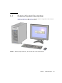
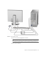
1.2
External System Description
FIGURE 1-1, FIGURE 1-2, and FIGURE 1-3 identify external components and connectors
of the Sun Ultra 45 or Ultra 25 workstation.
FIGURE 1-1
Monitor, Keyboard, Mouse, and Sun Ultra 45 or Ultra 25 Workstation
Chapter 1
Product Description
1-3
3
4
2
1
6
7
5
8
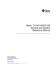
FIGURE 1-2
Front Panel Overview
TABLE 1-2
Front Panel Overview, Sun Ultra 45 and Ultra 25 Workstations
Callout in
1-4
FIGURE 1-2
Part Description
Symbol
1
DVD-dual drive slot
none
2
DVD-dual drive Eject button
3
Fault LED (not functional)
none
4
Workstation Status/Power LED (green)
none
5
Workstation Power button
6
Audio connector, microphone (pink)
7
Audio connector, headphone (lime green)
8
USB 2.x connector (2)
Sun Ultra 45 and Ultra 25 Workstations Service and Diagnostics Manual • May 2006
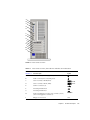
A
B
C
D
E
F
G
H
I
J
K
L
M
N
FIGURE 1-3
Rear Panel Overview
TABLE 1-3
Rear Panel Overview, Sun Ultra 45 and Ultra 25 workstations
Callout in
Rear Panel
Symbol
FIGURE 1-3
Part Description
A
Audio connector, line in (light blue)
B
Audio connector, line out (lime green)
C
Serial 2 connector TTYB (DB-9)
TTY B
D
Serial 1 connector TTYA (DB-9)
TTY A
E
USB 2.x connectors (4)
F
Twisted-pair Ethernet 0
G
Twisted-pair Ethernet 1
H
PCI-E 2 PCI-Express x8 lanes (long connector, slot 4)
(Shown with graphics accelerator)
PCI-E 2
I
Empty slot. Not used.
none
Chapter 1
Product Description
1-5
TABLE 1-3
Rear Panel Overview, Sun Ultra 45 and Ultra 25 workstations (Continued)
Callout in
FIGURE 1-3
Part Description
Rear Panel
Symbol
J
PCI-E 1 PCI-Express x8 lanes (long connector, slot 3)
PCI-E 0
K
PCI-E 0 PCI-Express x4 lanes (short connector, slot 2)
PCI-E 1
L
PCI-X 1 100 MHz 64-bit, 3.3 V
(long green connector, slot 1)
PCI-X 1
M
PCI-X 0 100 MHz 64-bit, 3.3 V
(long green connector, slot 0)
PCI-X 0
N
Power connector
none
Note – For details on PCI connectors, power consumption, and speeds see:
“Functional Description” on page C-1.
1.3
Supported Sun Monitors
The Sun Ultra 45 and Ultra 25 workstations support the monitors listed in TABLE 1-4.
The Sun XVR-100 graphics accelerator and the Sun XVR-2500 graphics accelerator
can both be configured to support multiple displays.
TABLE 1-4
Monitors supported by the Sun Ultra 45 and Ultra 25Workstations
Number of Monitors Supported
Monitor
Maximum resolution
Sun XVR-100
Sun XVR-2500
17-inch color CRT
1280 x 1024 @ 60 Hz
Up to 2
Up to 2
19-inch color LCD
1280 x 1024 @ 60/76 Hz
Up to 2
Up to 2
21-inch color CRT
1600 x 1200 @ 75 Hz
Up to 2
Up to 2
24-inch color LCD
1920 x 1200 @ 60 Hz
Up to 2*
Up to 2
*Sun XVR-100 will not support two monitors at 1920 x 1200.
For more information about the graphics accelerators, refer to:
■
■
1-6
Sun XVR-100 Graphics Accelerator Installation Guide, 816-7560
Sun XVR-2500 Graphics Accelerator Installation and User’s Guide, 817-7517
Sun Ultra 45 and Ultra 25 Workstations Service and Diagnostics Manual • May 2006
CHAPTER
2
Preparing to Replace Components
This chapter describes common tasks that must be completed prior to performing a
removal or installation procedure on any Sun Ultra 45 or Ultra 25 workstation.
The procedures described in this chapter are written for workstation service
providers and system administrators.
Caution – To prevent equipment damage, review the safety requirements, safety
symbols, and safety precautions in this chapter before you perform any replacement
procedure.
This chapter contains the following topics:
■
■
■
■
2.1
Section 2.1,
Section 2.2,
Section 2.3,
Section 2.4,
“Safety Information” on page 2-1
“Required Tools” on page 2-3
“Powering Off the Workstation” on page 2-4
“Finding Replacement Procedures” on page 2-7
Safety Information
This section provides safety precautions to follow when servicing the Sun Ultra 45 or
Ultra 25 workstation.
2.1.1
Safety Precautions
For your protection, observe the following safety precautions when setting up your
equipment:
2-1
■
Follow all Sun standard cautions, warnings, and instructions marked on the
equipment and described in Important Safety Information for Sun Hardware Systems,
816-7190.
■
Follow the cautions, warnings, and instructions in the Sun Ultra 45 and Ultra 25
Workstations Safety and Compliance Guide, 819-2785. The document is available
from:
http://www.sun.com/documentation/
2.1.2
■
Ensure that the voltage and frequency of your power source match the voltage
and frequency inscribed on the equipment’s electrical rating label.
■
Never push objects of any kind through openings in the equipment. Dangerous
voltages might be present. Conductive foreign objects could produce a short
circuit that could cause fire, electric shock, or damage to your equipment.
Safety Symbols
The following symbols might appear in this document:
Caution – There is a risk of personal injury and equipment damage. To avoid
personal injury and equipment damage, follow the instructions.
Caution – Hot surface. Avoid contact. Surfaces are hot and might cause personal
injury if touched.
Caution – Hazardous voltages are present. To reduce the risk of electric shock and
danger to personal health, follow the instructions.
2.1.3
Electrostatic Discharge Safety
Electrostatic discharge (ESD)-sensitive devices, such as the motherboard, PCI cards,
hard drives, and the NVRAM, require special handling.
Caution – The boards and hard drives contain electronic components that are
extremely sensitive to static electricity. Ordinary amounts of static electricity from
clothing or the work environment can destroy components. Do not touch the
components along their connector edges.
2-2
Sun Ultra 45 and Ultra 25 Workstations Service and Diagnostics Manual • May 2006
Caution – Wear an antistatic wrist strap and use an antistatic mat when handling
components such as drive assemblies, boards, or DIMMs. When servicing or
removing workstation components, attach an antistatic strap to your wrist and then
to a metal area on the chassis. Then disconnect the power cord from the workstation
and the wall receptacle. Following this caution equalizes all electrical potentials with
the workstation.
2.2
Required Tools
Use the following tools to service the Sun Ultra 45 or Ultra 25 workstations
(FIGURE 2-1):
■
■
■
■
■
No. 2 Phillips screwdriver
No. 0 Phillips screwdriver
Antistatic wrist strap
Antistatic mat
Container for screws
Small container
Antistatic mat
No. 0 Phillips screwdriver
Antistatic wrist strap
No. 2 Phillips screwdriver
FIGURE 2-1
Required Tools
Though not required for component replacement, the following tools have proven
helpful in certain situations:
■
■
■
■
Needle nose pliers, tweezers, or hemostat
Large jeweler’s screwdriver
Flashlight
Digital voltage meter (DVM)
Chapter 2
Preparing to Replace Components
2-3
Place ESD-sensitive components such as the motherboard, memory, PCI cards, hard
drives, and the NVRAM on an antistatic mat. The following items can be used as an
antistatic mat:
2.3
■
Antistatic bag used to wrap a Sun replacement part
■
Sun ESD mat, part number 250-1088 (available through your Sun sales
representative)
■
Disposable ESD mat (shipped with replacement parts or optional system
components)
Powering Off the Workstation
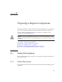
1. Notify any affected users that the system will be powered down.
2. Save any open files and quit all applications.
3. Press and release the Power button or the Sleep key (FIGURE 2-2).
If you pressed the Sleep key, select “Shutdown,” from the menu.
Caution – If the system is not running the Solaris Operating System (OS), you may
need to press and hold the Power button for five seconds. The file system could be
corrupted. For more information, refer to the documentation for the operating
system in use.
4. Power off and disconnect any peripherals (FIGURE 2-3).
5. Disconnect the keyboard, mouse, monitor, and network connections.
2-4
Sun Ultra 45 and Ultra 25 Workstations Service and Diagnostics Manual • May 2006
FIGURE 2-2
Power Button and Sleep Key Location
FIGURE 2-3
Disconnecting the Workstation Cables
Chapter 2
Preparing to Replace Components
2-5
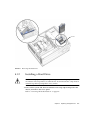
2.3.1
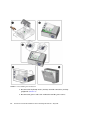
Opening the Workstation
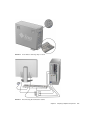
1. Press down the two latches on the side cover and lift the cover off the workstation
(FIGURE 2-4).
2. Using both hands, place the workstation on its side.
3. Pivot the workstation support stabilizer underneath the workstation.
4. Attach the antistatic wrist strap.
Wrap the adhesive portion around your wrist. Attach the copper end to the rear vent
of the chassis. Ensure that the location does not interfere with your service
procedure.
5. Remove the access panel:
a. Slide the lock block towards the front of the system.
b. Press and release the two latches and lift the access panel.
6. Disconnect the power cord from the workstation.
7. If necessary, remove any long PCI cards and pull the fan tray out of the chassis.
8. Find your removal or replacement procedure (TABLE 2-1).
2-6
Sun Ultra 45 and Ultra 25 Workstations Service and Diagnostics Manual • May 2006
FIGURE 2-4
2.4
Removing the Side Cover and Access Panel
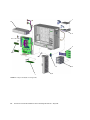
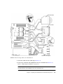
Finding Replacement Procedures
Identify the component that you need to replace in FIGURE 2-5 and refer to TABLE 2-1
to find the replacement procedure.
Chapter 2
Preparing to Replace Components
2-7
1
10
2
9
3
8
5
7
FIGURE 2-5
2-8
6
Major Workstation Components
Sun Ultra 45 and Ultra 25 Workstations Service and Diagnostics Manual • May 2006
4
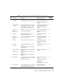
TABLE 2-1
Item
No.
Sun Ultra 45 or Ultra 25 Workstation Replaceable Components
Animated
Procedure?
Component
Description
Replacement Procedure
1
DVD-dual drive
and cable
Slot loading DVD-dual drive with one
combined cable for power and signal
“Replacing the I/O Module
With the DVD-Dual Drive
and Audio USB Board” on
page 4-6
Yes
2
I/O module with
two cables
USB and audio board with speaker,
mounting bracket, audio connectors,
system LEDs, Power button. One
signal cable and one power cable
“Replacing the I/O Module
With the DVD-Dual Drive
and Audio USB Board” on
page 4-6
Yes
3
Hard drive
backplane and
cable
Hard drive connector board with one
SAS or SATA signal cable
“Replacing the Hard Drive
Backplane and Cables” on
page 4-4
Yes
4
Hard drive
Either 250GB, 7,200 rpm SATA, or
146 GB, 15,000 rpm SAS
“Replacing a Hard Drive”
on page 4-2
Yes
5
Fan tray
backplane and
cable
Connector board with one combined
signal and power cable
“Replacing the Fan Tray
and Fan Tray Backplane”
on page 5-1
No
6
Fan tray
Fan tray with three fans, 12 VDC
“Replacing the Fan Tray
and Fan Tray Backplane”
on page 5-1
Yes
7
Graphics
accelerator
Sun XVR-100 graphics accelerator
(PCI-X)
Sun XVR-2500 graphics accelerator
(PCI Express)
“Replacing the PCI Cards”
on page 3-13
Yes
8
DIMM (512 MB)
DIMM, 512 MB, DDR-1 SDRAM 266
MHz, ECC
DIMM, 1 GB, DDR-1 SDRAM 266
MHz, ECC
DIMM, 2 GB, DDR-1 SDRAM 266
MHz, EC
“Replacing the DIMMs” on
page 3-3
Yes
DIMM (1 GB)
DIMM (2 GB)
9
Motherboard
Sun Ultra 45 or Ultra 25 workstation
motherboard with one or two CPUs,
NVRAM, and battery
“Replacing the Battery” on
page 3-9
“Replacing the NVRAM”
on page 3-11
“Replacing the
Motherboard” on page 3-20
Yes
10
Power supply
Power Supply, 1000 W, 100 – 240 VAC
(With five cables connected. One cable
is not used in this workstation).
“Replacing the Power
Supply” on page 5-4
Yes
Chapter 2
Preparing to Replace Components
2-9
Note – The components listed in TABLE 2-1 are subject to change without notice.
Consult your authorized Sun sales representative or service provider to confirm a
part number prior to ordering a replacement component, or search this web site:
http://www.sun.com/ibb/spares/
2-10
Sun Ultra 45 and Ultra 25 Workstations Service and Diagnostics Manual • May 2006
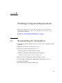
CHAPTER
3
Replacing the Motherboard and
Associated Components
This chapter describes the removal and installation procedures for the Sun Ultra 45
and Ultra 25 motherboard and associated components.
Note – Only Sun authorized service providers should perform the procedures
described in “Replacing the Motherboard” on page 3-20.
This chapter contains the following topics:
■
■
■
■
■
■
Section 3.1,
Section 3.2,
Section 3.3,
Section 3.4,
Section 3.5,
Section 3.6,
“Motherboard Connector Overview” on page 3-2
“Replacing the DIMMs” on page 3-3
“Replacing the Battery” on page 3-9
“Replacing the NVRAM” on page 3-11
“Replacing the PCI Cards” on page 3-13
“Replacing the Motherboard” on page 3-20
Caution – To prevent equipment damage, review the safety requirements, safety
symbols, and safety precautions in “Preparing to Replace Components” on page 2-1
before you perform any replacement procedure. Additional cautions, warnings, and
instructions are provided in the Sun Ultra 45 and Ultra 25 Workstations Safety and
Compliance Guide, 819-2785. The document is available from:
http://www.sun.com/documentation/
Caution – When servicing or removing workstation components, attach an
antistatic strap to your wrist and then to a metal area on the chassis. Then disconnect
the power cord from the workstation and the wall receptacle. Following this caution
equalizes all electrical potentials within the workstation.
3-1
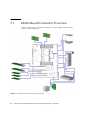
3.1
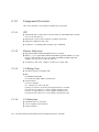
Motherboard Connector Overview
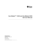
FIGURE 3-1 and FIGURE 3-2 show the connections for some cables and devices that
connect to the motherboard.
P4
not used
FIGURE 3-1
3-2
Motherboard With Component Connections
Sun Ultra 45 and Ultra 25 Workstations Service and Diagnostics Manual • May 2006
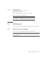
FIGURE 3-2
3.2
Motherboard Cables and Cable Clips
Replacing the DIMMs
This section describes removal and installation of the memory modules.
Caution – DIMM memory is installed in pairs. If you replace a single DIMM, the
new DIMM must be identical to the DIMM that you removed.
Caution – Handle the DIMMs along the outside edges. Do not handle the DIMM
along the gold contact edge. Do not touch DIMM components or other metal parts.
Always wear an antistatic wrist strap when handling DIMMs.
Chapter 3
Replacing the Motherboard and Associated Components
3-3
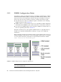
3.2.1
DIMM Configuration Rules
Sun Ultra 45 or Ultra 25 workstation memory is installed as matched pairs of DDR-1
SDRAM 266-MHz DIMMs. Within a matched pair, DIMMs must be identical. They
must be from the same manufacturer with the same type and number of memory
devices, the same amount of memory per device, and the same memory speed.
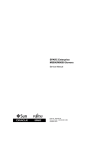
■
The Sun Ultra 45 or Ultra 25 workstation requires a minimum of two matching
DIMMs installed in CPU0 (FIGURE 3-3).
■
DIMM connectors on the motherboard are color-coded blue and black. Beginning
with CPU0, install DIMMS in pairs, either in the blue or in the black connectors.
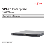
■
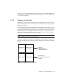
If you have four DIMMS and two CPUs, install two DIMMs for CPU0 and two for
CPU1 for optimum performance (FIGURE 3-4).
When the workstation boots, the OpenBoot PROM checks for compatible memory
modules. See “OpenBoot PROM Memory Message” on page 3-6 for additional
information.
Before replacing Sun Ultra 45 and Ultra 25 memory, verify that the latest versions of
OpenBoot PROM, system firmware, and recommended system patches are installed
on your system. If necessary, check the Sun System Handbook at SunSolve Online:
http://sunsolve.sun.com/handbook_pub/
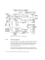
FIGURE 3-3
DIMM Configurations for Single-CPU Workstations
Note – The Ultra 25 workstation has one CPU (CPU0) and one bank of four DIMM
slots on the motherboard.
3-4
Sun Ultra 45 and Ultra 25 Workstations Service and Diagnostics Manual • May 2006
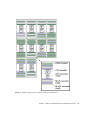
FIGURE 3-4
DIMM Configurations for Ultra 45 Dual-CPU Workstations
Chapter 3
Replacing the Motherboard and Associated Components
3-5
3.2.2
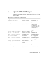
OpenBoot PROM Memory Message
During workstation startup, OpenBoot PROM checks for DIMM type and DIMM
manufacturer. TABLE 3-1 shows some checks and the actions taken by the OpenBoot
PROM.
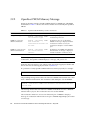
TABLE 3-1
OpenBoot PROM Memory Checks and Actions
Check
Message
Action Taken by System
Wrong DIMM type
NOTICE - CPUx Banky DIMMs
are incorrect type.
A message is displayed and the
workstation powers off.
DIMMs in a pair have
different architecture
NOTICE - CPUx Banky DIMMs
have different
architectures and will not
be used.
Workstation does not use dissimilar
DIMMs. A message is displayed and the
workstation continues to boot; the
workstation attempts to use the DIMM
pair.
DIMMs in a pair are from
different manufacturers
NOTICE - CPUx Banky DIMMs
are from different
vendors.
Workstation uses DIMMs from different
manufacturers. A message is displayed
and the workstation continues to boot.
Note – If you only have one DIMM pair installed and those DIMMs have different
architectures, the OpenBoot PROM displays a message, and powers off.
Each CPU has four memory slots. The two blue slots make up physical bank 0 and
the two black slots make up physical bank 1 (FIGURE 3-4).
If a problem is found, OpenBoot PROM references memory by bank, for example:
NOTICE - CPU0 Bank 0 DIMMS are from different vendors.
The preceding message means that each of the two DIMMs in the bank 0 slots comes
from a different manufacturer. The workstation still attempts to use the DIMMs.
NOTICE - CPU0 Bank 1 DIMMs have different architectures and will
not be used.
This message means that each of the two DIMMs in the black slots has a different
internal memory layout. The workstation does not use the DIMMs.
The workstation must have at least one functional pair of DIMMs to display a
message. A workstation with more than one pair of DIMMs might display more than
one message.
3-6
Sun Ultra 45 and Ultra 25 Workstations Service and Diagnostics Manual • May 2006
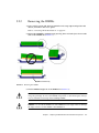
3.2.3
Removing the DIMMs
1. Power off the system and attach an antistatic wrist strap. Open and position the
chassis, and remove the access panel.
Refer to “Powering Off the Workstation” on page 2-4.
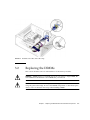
2. Release the DIMM by simultaneously pressing down on both ejector levers at the
ends of the DIMM slot (FIGURE 3-5).
DIMM connector key
FIGURE 3-5
Releasing the DIMM
3. Lift the DIMM straight out of the DIMM slot (FIGURE 3-5).
Caution – Handle the DIMMs along the outside edges. Do not handle DIMMs
along the gold edge. Do not touch DIMM components or other metal parts. Always
wear an antistatic wrist strap when handling DIMMs.
Caution – Do not lift the DIMM out of the DIMM slot at an angle. This can damage
the edge connector for the DIMM or the DIMM slot.
Chapter 3
Replacing the Motherboard and Associated Components
3-7
4. Set the DIMM aside on an antistatic mat.
5. Repeat Step 2 through Step 4 until you have removed all relevant DIMMs.
3.2.4
Installing the DIMMs
Caution – If you are installing additional memory, remember that DIMMs must be
installed in matched pairs of DIMMs (FIGURE 3-4). The workstation requires a
minimum of one pair of matching DIMMs.
The minimum OpenBoot Prom level for the Sun Ultra 45 or Ultra 25 workstations is
OpenBoot 4.21.x. Before installing Sun Ultra 45 and Ultra 25 memory, verify that the
latest versions of OpenBoot PROM, system firmware, and recommended system
patches are installed on your system. If necessary, check the Sun System Handbook at
SunSolve Online:
http://sunsolve.sun.com/handbook_pub/
Note – If your Ultra 45 workstation has two CPUs and four DIMMs, the
workstation operates most efficiently with two DIMMs per CPU. DIMM connectors
are color-coded blue and black. You must install DIMMs in pairs in the same color
connectors.
Caution – Use proper ESD grounding techniques when handling components. Wear
an antistatic wrist strap and use an antistatic mat. Store ESD-sensitive components in
antistatic bags before placing them on any surface.
Caution – Do not remove any DIMM from its antistatic package until you are ready
to install it.
1. Power off the system, attach an antistatic wrist strap, open and position the
chassis, and remove the access panel.
Refer to “Powering Off the Workstation” on page 2-4.
2. Remove the new DIMM from its antistatic container.
Caution – Handle DIMMs only by the edges. Do not touch DIMM components or
metal parts. Always wear an antistatic wrist strap when handling DIMMs.
3-8
Sun Ultra 45 and Ultra 25 Workstations Service and Diagnostics Manual • May 2006
3. Review the recommended DIMM installation and configurations before installing
the DIMM.
See “Replacing the DIMMs” on page 3-3.
Caution – If you replace a single DIMM, the replacement DIMM must be identical
to the DIMM that you removed.
4. Align the DIMM notch to the DIMM connector key (FIGURE 3-5).
5. Using both thumbs, press the DIMM straight down into the DIMM connector slot
until both ejector levers close (FIGURE 3-5).
The DIMM is seated when you hear a click and the ejector levers are in the vertical
position.
6. Repeat Step 4 through Step 5 until all DIMMs are installed.
7. Verify that all DIMM ejector levers are upright, seated, and tight.
8. Reassemble the workstation, power on the system, and verify the DIMM
installation.
Refer to “Reassembling the Workstation” on page 6-1 and “Verifying Component
Installation” on page 6-5. You also might want to review the information in
“OpenBoot PROM Memory Message” on page 3-6.
3.3
Replacing the Battery
This section describes removal and installation of the battery. TABLE 3-2 lists the
battery specifications.
TABLE 3-2
Battery Specifications
Specification
Value
Voltage
3 VDC
Type
CR 2032
Chapter 3
Replacing the Motherboard and Associated Components
3-9
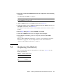
3.3.1
Removing the Battery
1. Power off the system and attach an antistatic wrist strap. Open and position the
chassis, and remove the access panel.
Refer to “Powering Off the Workstation” on page 2-4.
2. Release the battery by pressing the battery clip away from the battery until the
battery shifts out of the battery socket (FIGURE 3-6).
3. Remove the battery.
Battery clip
FIGURE 3-6
Removing and Installing the Battery
Note – The workstation does not function without the battery.
3-10
Sun Ultra 45 and Ultra 25 Workstations Service and Diagnostics Manual • May 2006
3.3.2
Installing the Battery
The battery fits directly into a socket on the motherboard. There are no additional
fasteners or cables.
1. Position the battery over the battery socket with the plus (+) side up (FIGURE 3-6).
2. Press the battery down into the socket until the battery clicks into place.
3. Reassemble the workstation, power on the system, and verify the battery
installation.
Refer to “Finishing Component Replacement” on page 6-1 and “Verifying
Component Installation” on page 6-5.
3.4
Replacing the NVRAM
This section describes removal and installation of the nonvolatile random access
memory (NVRAM).
Note – If you are replacing a motherboard and you have software that is licensed to
the HostID or Ethernet address, you should install the old NVRAM on the new
motherboard.
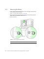
3.4.1
Removing the NVRAM
1. Power off the system and attach an antistatic wrist strap. Open and position the
chassis, and remove the access panel.
Refer to “Powering Off the Workstation” on page 2-4.
2. Pull the NVRAM straight up from the motherboard connector (FIGURE 3-7).
Chapter 3
Replacing the Motherboard and Associated Components
3-11
NVRAM key
12345678
MAC address
FIGURE 3-7
Removing and Installing the NVRAM
3. Set the NVRAM aside on an antistatic mat.
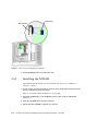
3.4.2
Installing the NVRAM
The NVRAM installs directly onto the motherboard. There are no additional
fasteners or cables.
1. Power off the system and attach an antistatic wrist strap. Open and position the
chassis, and remove the access panel.
Refer to “Powering Off the Workstation” on page 2-4.
2. Align the NVRAM key to the NVRAM connector key on the motherboard
(FIGURE 3-7).
3. Press the NVRAM down into the connector.
4. Ensure that the NVRAM is tight in its connector.
3-12
Sun Ultra 45 and Ultra 25 Workstations Service and Diagnostics Manual • May 2006
5. If you are finished working, reassemble the workstation, power on the
workstation, and verify the NVRAM installation.
Refer to “Finishing Component Replacement” on page 6-1 and “Verifying
Component Installation” on page 6-5.
3.5
Replacing the PCI Cards
This section describes removal and installation of PCI cards in the workstation.
3.5.1
Identifying the PCI Cards
There are five PCI connectors on the system motherboard. Two connectors are PCI-X,
and three connectors are PCI-Express (FIGURE 3-8). The long PCI-E connectors are x16
physical lanes long and operate at x8 lanes. The short PCI-E connector is x8 lanes
long and operates at x4 lanes.
Chapter 3
Replacing the Motherboard and Associated Components
3-13
PCI-E2 x8
Blank slot
PCI-E1 x8
PCI-E0 x4
PCI-X1 100 MHz
PCI-X0 100 MHz
FIGURE 3-8
3.5.2
PCI Card Location and Identification
Removing a PCI Card
1. Power off the system and attach an antistatic wrist strap. If necessary, disconnect
external cables. Open and position the chassis, and remove the access panel.
Refer to “Powering Off the Workstation” on page 2-4.
2. Using a No. 2 Phillips screwdriver, remove the screw that secures the PCI card
retainer to the chassis rear panel (FIGURE 3-9).
Set the screw aside in a container.
Caution – If you are removing a graphics accelerator from a PCI-Express connector,
be sure that you release the PCI-E connector latch (FIGURE 3-9).
3-14
Sun Ultra 45 and Ultra 25 Workstations Service and Diagnostics Manual • May 2006
3. Gently rock the PCI card forward, then lift it straight out of the PCI card slot, and
set it aside on an antistatic mat.
FIGURE 3-9
Removing the PCI Card
4. If you are not installing another PCI card in the empty slot, insert a filler panel
into the rear panel slot.
The rear panel slot must be closed with a filler panel to meet system Electromagnetic
Interference (EMI) and airflow requirements.
3.5.3
General PCI Card Guidelines
The total power consumption of all installed PCI cards must not exceed 400 Watts.
Chapter 3
Replacing the Motherboard and Associated Components
3-15
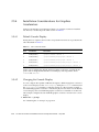
3.5.4
Installation Considerations for Graphics
Accelerators
PCI-E 2 is the default console display. If there is no graphics accelerator installed
into PCI-E 2, consider the probe order shown in TABLE 3-3.
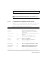
3.5.4.1
Default Console Display
During the boot sequence, device nodes are probed. The PCI slots are probed in the
order described in TABLE 3-3.
TABLE 3-3
PCI Card Probe Order
Probe
Order
Slot Identifier
Device Node
1
PCI4 (PCI-E 2)
/pci@1f,700000/ device 0
2
PCI2 (PCI-E 0)
/pci@1e,600000/pci@0/pci@3/ device 0
3
PCI3 (PCI-E 1)
/pci@1e,600000/pci@0/pci@8/ device 0
4
PCI1 (PCI-X 1)
/pci@1e,600000/pci@0/pci@9/pci@0,2/ device 1
5
PCI0 (PCI-X 0)
/pci@1e,600000/pci@0/pci@9/pci@0,2/ device 2
Unless you reconfigure the default, the first graphics accelerator occurring in the
probe order is designated the default console display and assigned the aliases
screen and /dev/fb.
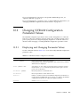
3.5.4.2
Changing the Console Display
You can configure the OpenBoot PROM to designate a different graphics accelerator
as the console display. Use the show-displays utility, the nvalias command, and
the output-device parameter to make this change. For the following example, a
Sun XVR-2500 graphics accelerator is installed in physical slot PCI-E 2 as the default
console display and a Sun XVR-100 graphics accelerator is installed in slot PCI-X 0.
This example configures the Sun XVR-100 graphics accelerator to be the new console
display.
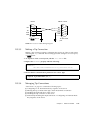
1. Obtain the ok prompt.
See “Obtaining the ok Prompt” on page 10-2.
3-16
Sun Ultra 45 and Ultra 25 Workstations Service and Diagnostics Manual • May 2006
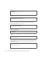
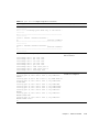
2. Display the device nodes for the installed graphics accelerators.
For example:
ok
a)
b)
q)
show-displays
/pci@1f,700000/SUNW,XVR-2500@0
/pci@1e,600000/pci@0/pci@9/pci@0,2/SUNW,XVR-100@2
NO SELECTION
3. Select the graphics accelerator to be the new console display by typing its
respective letter.
For example:
Enter Selection, q to quit: b
The utility ends and the device node path is loaded into a text buffer.
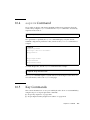
4. Make an alias for the device node path.
For example:
ok nvalias newconsoledisplay (Ctrl + Y)
Type a space, hold down the Control key, and press the Y key.
5. Configure the output-device parameter for the new console display.
For example:
ok setenv output-device newconsoledisplay
6. Reset the OpenBoot PROM:
ok reset-all
The system now uses the Sun XVR-100 graphics accelerator as the new console
display.
Note – The default console display, the first graphics accelerator found in probe
order, is still aliased to screen. If you want to check the new console display, type:
test newconsoledisplay
Chapter 3
Replacing the Motherboard and Associated Components
3-17
3.5.5
Installing a PCI Card
1. Power off the system and attach an antistatic wrist strap. If necessary, disconnect
external cables. Open and position the chassis, and remove the access panel.
Refer to “Powering Off the Workstation” on page 2-4.
2. Locate the available PCI card slots.
You might have to remove a second chassis filler panel for some PCI cards that use
two PCI card slots. Read the documentation that came with the PCI card and see
“General PCI Card Guidelines” on page 3-15.
FIGURE 3-10
3-18
Installing a PCI Card
Sun Ultra 45 and Ultra 25 Workstations Service and Diagnostics Manual • May 2006
3. Using a No. 2 Phillips screwdriver, remove the chassis filler panel from the PCI
card slot and set the screw aside in a container (FIGURE 3-10).
Remove a second filler panel if needed for dual-width PCI cards.
4. Remove the new PCI card from its antistatic container.
Caution – Handle the PCI card along the outside edges. Do not handle the PCI card
along the contact edge. If you are installing a long PCI-E card, be sure to engage the
PCI-E connector latch.
5. Position the PCI card so that the PCI bracket aligns with the chassis rear panel
slot and the PCI card edge aligns with the motherboard PCI card connector.
6. Insert the PCI card into the PCI card slot.
If you are installing a long PCI-Express card, be sure to engage the PCI-E connector
latch (FIGURE 3-10).
7. Firmly press the PCI card straight down into the PCI card slot until it is fully
seated in the slot.
8. Use a No. 2 Phillips screwdriver to fasten the screw that secures the PCI card
retainer (FIGURE 3-10).
9. Inspect the PCI card fasteners to verify that:
■
■
The PCI card panel slot screws are tight.
The PCI cards are secure in the connectors.
10. If you are finished working, reassemble the workstation, power on the
workstation, and verify the PCI card installation.
Refer to “Finishing Component Replacement” on page 6-1.
Note – Boot the system with the -r option, so that the Solaris Operating System can
reconfigure itself for the new component. See “Finishing Component Replacement”
on page 6-1.
Chapter 3
Replacing the Motherboard and Associated Components
3-19
3.6
Replacing the Motherboard
This section describes removal and installation of the motherboard.
Caution – This procedure is intended for Sun authorized service providers only.
3.6.1
Removing the Motherboard
The motherboard, CPU, and NVRAM are a single replaceable unit.
1. Power off the system and attach an antistatic wrist strap. Disconnect all external
cables; open and position the chassis, and remove the access panel.
Refer to “Powering Off the Workstation” on page 2-4.
2. If necessary, remove the PCI cards and DIMMs (FIGURE 3-11).
Refer to:
■
■
“Removing the DIMMs” on page 3-7
“Removing a PCI Card” on page 3-14
Set these components onto an antistatic mat (FIGURE 3-11).
3. Remove the fan tray.
4. (Optional) If you want to use the same Ethernet address and system ID for the
new motherboard, remove the NVRAM and place it on an antistatic mat.
Refer to “Removing the NVRAM” on page 3-11.
Note – If you have software that is licensed to the HostID or Ethernet address, you
should install the old NVRAM on the new motherboard.
5. Remove all cables from the cable clips (FIGURE 3-11).
3-20
Sun Ultra 45 and Ultra 25 Workstations Service and Diagnostics Manual • May 2006
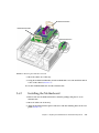
FIGURE 3-11
Removing Components from the Motherboard
Chapter 3
Replacing the Motherboard and Associated Components
3-21
6. Disconnect the following power and signal cables from the motherboard
(FIGURE 3-12):
■
■
■
■
■
■
FIGURE 3-12
I/O module signal and power cable at connector J3
I/O module USB cable at connector J36
DVD-dual drive cable at connector J11
Fan tray backplane cable at connector J20
Power supply cables at connectors J22, J28, J45 (P1, P2, and P5)
Hard drive signal cable connector J42
Disconnecting Motherboard Cables
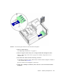
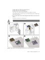
7. Turn the motherboard latch 90 degrees counterclockwise (FIGURE 3-13).
3-22
Sun Ultra 45 and Ultra 25 Workstations Service and Diagnostics Manual • May 2006
Motherboard handle
Motherboard handle
Motherboard latch
FIGURE 3-13
Releasing the Motherboard Latch
8. Move the cables out of the way.
9. Using the motherboard handles, tilt the motherboard to one side and lift it until it
is free of the chassis (FIGURE 3-13).
10. Set the motherboard down onto the antistatic mat.
3.6.2
Installing the Motherboard
1. Remove the new motherboard from its antistatic package and place it on an
antistatic mat.
2. Move all cables out of the way.
3. Align the motherboard rear panel connectors with the matching holes in the rear
panel (FIGURE 3-13).
Chapter 3
Replacing the Motherboard and Associated Components
3-23
4. Gently lower the motherboard while tilting it down (FIGURE 3-13).
5. Align the motherboard so that the hooks fit into the holes of the motherboard tray.
Caution – Ensure that the hooks are located in the holes. Improper alignment can
damage the motherboard.
6. Turn the motherboard latch 90 degrees clockwise to secure the motherboard.
Ensure that the motherboard connector panel aligns with the chassis rear panel.
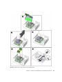
7. Connect the cables to the corresponding motherboard connectors (FIGURE 3-14):
■
■
■
■
■
■
3-24
I/O module signal and power cable at connector J3
I/O module USB cable at connector J36
DVD-dual drive connector at J11
Fan tray backplane cable at connector J20
Power supply cables at connectors J22, J28, and J45 (P1, P2, and P5)
Hard drive signal cable connector J42
Sun Ultra 45 and Ultra 25 Workstations Service and Diagnostics Manual • May 2006
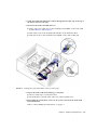
DVD-dual drive
J3
I/O module
J11
J20
J22 (P2)
J28 (P1)
Fan tray backplane
J36
J42
P4
(not used)
J45/P5
J2
Power supply
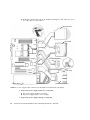
FIGURE 3-14
Hard drive backplane
Reconnecting Cables to the Motherboard
8. Secure the cables into the cable clips (FIGURE 3-14).
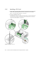
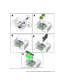
9. If necessary, install the old NVRAM onto the new motherboard (FIGURE 3-15).
Refer to “Replacing the NVRAM” on page 3-11.
Note – If you have software that is licensed to the HostID or Ethernet address, you
should install the old NVRAM on the new motherboard.
Chapter 3
Replacing the Motherboard and Associated Components
3-25
10. Install the PCI cards and the DIMMs.
Refer to:
■
■
“Installing a PCI Card” on page 3-18
“Replacing the DIMMs” on page 3-3
11. Inspect the motherboard to verify that:
■
■
■
■
Cable connections are tight and cable clips are secured.
DIMMs are properly installed.
NVRAM is tight in the socket.
PCI cards are properly seated and secured.
12. Reassemble the workstation, power on the system, and verify the motherboard
installation.
Refer to “Finishing Component Replacement” on page 6-1.
3-26
Sun Ultra 45 and Ultra 25 Workstations Service and Diagnostics Manual • May 2006
FIGURE 3-15
Installing the Motherboard and Related Components
Chapter 3
Replacing the Motherboard and Associated Components
3-27
3-28
Sun Ultra 45 and Ultra 25 Workstations Service and Diagnostics Manual • May 2006
CHAPTER
4
Replacing Storage Devices
This chapter describes the removal and installation procedures for Sun Ultra 45 or
Ultra 25 workstation storage devices.
The procedures described in this chapter are written for workstation service
providers and system administrators.
This chapter contains the following topics:
■
■
■
Section 4.1, “Replacing a Hard Drive” on page 4-2
Section 4.2, “Replacing the Hard Drive Backplane and Cables” on page 4-4
Section 4.3, “Replacing the I/O Module With the DVD-Dual Drive and Audio
USB Board” on page 4-6
Caution – To prevent equipment damage, review the safety information in
“Preparing to Replace Components” on page 2-1 before you perform any
replacement procedure. Additional cautions, warnings, and instructions are
provided in the Sun Ultra 45 and Ultra 25 Workstations Safety and Compliance Guide,
819-2785. The document is available from:
http://www.sun.com/documentation.
Caution – When servicing or removing workstation components, attach an
antistatic strap to your wrist and then to a metal area on the chassis. Then disconnect
the power cord from the workstation and the wall receptacle. Following this caution
equalizes all electrical potentials with the workstation.
4-1
4.1
Replacing a Hard Drive
The workstation supports up to four hard drives, either serial ATA (SATA), or serial
attached SCSI (SAS). The hard drives slide into the hard drive bay and use standard
Sun hard drive mounting brackets.
Note – Sun does not support mixed SAS and SATA hard drives. All four installed
hard drives must be the same type.
Caution – The Sun SATA and SAS hard drive brackets are gray. To prevent damage
to the connectors, do not insert any other color of hard drive into Sun Ultra 45 or
Ultra 25 workstations.
The hard drives are labeled HDD0 through HDD3. The default boot drive is HDD0
(FIGURE 4-1).
TABLE 4-1 lists the hard drive specifications.
TABLE 4-1
Hard Drive Specifications
Hard Drive
Specification
SATA 100
250GB, 7,200 rpm, 3.5 inch, (gray bracket)
80GB, 7,200 rpm, 3.5 inch, (gray bracket) for
Ultra 25 workstation.
SAS
4.1.1
146GB, 15,000 rpm, 3.5 inch (gray bracket)
Removing a Hard Drive
1. Power off the system and attach an antistatic wrist strap. Open and position the
chassis, and remove the access panel.
Refer To “Powering Off the Workstation” on page 2-4.
2. Press the hard drive release button to release the hard drive handle (FIGURE 4-1).
3. Grasp the hard drive handle and pull the hard drive out of the hard drive bay.
4. Set the hard drive aside on an antistatic mat.
4-2
Sun Ultra 45 and Ultra 25 Workstations Service and Diagnostics Manual • May 2006
HDD0
FIGURE 4-1
4.1.2
Removing the Hard Drive
Installing a Hard Drive
Caution – Use proper ESD grounding technique when handling components. Wear
an antistatic wrist strap and use an antistatic mat. Store ESD-sensitive components in
antistatic bags before placing them on any surface.
1. Power off the system and attach an antistatic wrist strap. Open and position the
chassis, and remove the access panel.
Refer to “Powering Off the Workstation” on page 2-4.
Chapter 4
Replacing Storage Devices
4-3
Note – The default boot device is installed in HDD0 (drive 0). Be sure to install the
boot disk in HDD0, unless you have changed the boot device parameters.
2. Remove the new hard drive from its packaging.
Caution – The Sun SATA and SAS hard drive brackets are color-coded gray. To
prevent damage to the connectors, do not insert any other color of hard drive into
Sun Ultra 45 or Ultra 25 workstations.
3. Install the hard drive (FIGURE 4-1).
4. Slide the hard drive into the hard drive bay.
5. Close the latch on the hard drive until it clicks and is secure.
6. If you are finished working, reassemble the workstation, power on the
workstation, and verify the hard drive installation.
See “Finishing Component Replacement” on page 6-1.
Note – Boot the system with the -r option, so that the Solaris Operating System can
reconfigure itself for the new component. See “Finishing Component Replacement”
on page 6-1.
4.2
Replacing the Hard Drive Backplane and
Cables
This section describes removal and installation of the hard drive backplane, the
signal cable, and the power cable.
4.2.1
Removing the Hard Drive Backplane and Cables
1. Power off the system and attach an antistatic wrist strap. Open and position the
chassis, and remove the access panel.
Refer to “Powering Off the Workstation” on page 2-4.
4-4
Sun Ultra 45 and Ultra 25 Workstations Service and Diagnostics Manual • May 2006
FIGURE 4-2
Disconnecting the Cables From the Hard Drive Backplane
2. Remove all hard drives.
See “Replacing a Hard Drive” on page 4-2.
3. Remove long PCI cards if they are covering the hard drive backplane cables.
Refer to “Removing a PCI Card” on page 3-14. Set these components onto an
antistatic mat.
4. Disconnect the cables from the following connectors
■
Hard drive backplane signal cable from J4 of the hard drive backplane and J42 on
the motherboard (FIGURE 4-2)
■
Power cable P3 from backplane connector J2
5. Using a No. 2 Phillips screwdriver, remove the two screws from the hard drive
backplane.
Chapter 4
Replacing Storage Devices
4-5
4.2.2
Installing the Hard Drive Backplane and Cables
1. Remove the new hard drive backplane and cables from the packaging.
2. Using a No. 2 Phillips screwdriver, replace the two screws for the hard drive
backplane.
3. Reconnect the cables to the following connectors:
■
Power cable P3 on backplane connector J2 (FIGURE 4-2).
■
Hard drive backplane signal cable from J4 of the hard drive backplane and J42 on
the motherboard
4. Inspect the cabling to verify that the signal and power cables are both secure at
the backplane and the motherboard.
5. If you removed any long PCI cards, replace them.
Refer to “Installing a PCI Card” on page 3-18.
6. Reassemble the workstation. Power on the system, and verify the cable
installation.
Refer to:
■
■
4.3
“Reassembling the Workstation” on page 6-1
“Verifying Component Installation” on page 6-5
Replacing the I/O Module With the
DVD-Dual Drive and Audio USB Board
This section describes removal and installation of the I/O module. The I/O module
contains the DVD-dual drive, the audio USB board with speaker, USB and audio
connectors, and the Power button and LED.
4.3.1
Removing the I/O Module and DVD-Dual Drive
1. Power off the system and attach an antistatic wrist strap. Open and position the
chassis, and remove the access panel.
Refer to “Powering Off the Workstation” on page 2-4.
2. Open the I/O cable clip at the top of the chassis (FIGURE 4-3).
3. Disconnect the following cables:
4-6
Sun Ultra 45 and Ultra 25 Workstations Service and Diagnostics Manual • May 2006
■
■
■
Audio and power cable at J3 on the motherboard
DVD cable at J11 on the motherboard
USB cable from at J36 on the motherboard.
New cables are provided with the DVD-dual drive and the I/O module.
If you need to remove a long PCI card to access the USB cable, refer to “Removing a
PCI Card” on page 3-14.
4. Press the I/O module release button and pull the I/O module out the front of the
chassis.
Place the I/O module on an antistatic mat.
Caution – Do not attempt to remove the bezel from the front of the I/O module.
FIGURE 4-3
Removing the I/O Module With the DVD-Dual Drive and Audio USB Board
Chapter 4
Replacing Storage Devices
4-7
5. If you are only replacing the DVD-dual drive:
a. Using a No. 0 Phillips screwdriver, remove the screws holding the DVD-dual
drive into the I/O module.
b. Pull the DVD-dual drive straight out the back of the removable media bay
(FIGURE 4-3).
6. If you are replacing the audio USB board:
a. Remove the DVD-dual drive and set it aside.
b. Using a No. 2 Phillips screwdriver, remove the four screws that secure the
audio USB board to the I/O module.
c. Pull the audio USB board straight out the back of the removable media bay
(FIGURE 4-3).
4.3.2
Installing the I/O Module and DVD-Dual Drive
1. Remove the I/O module and DVD-dual drive assembly from the packaging.
2. If you are replacing the audio USB board:
a. Install the new audio USB board into the removable media bay (FIGURE 4-3).
b. Replace all four screws that secure the audio USB board to the removable
media bay.
3. Install the DVD-dual drive into the I/O module with the screws (FIGURE 4-3):
a. If you are using the old DVD-dual drive, screw the old drive into the I/O
module.
b. If you are using a new DVD-dual drive, screw the new drive into the I/O
module.
4. Push the I/O module and DVD-dual drive into the chassis until the module clicks
(FIGURE 4-3).
5. Connect the cables to the DVD-dual drive and the audio USB board.
If you removed a long PCI card, replace it now. Refer to Section 3.5.5, “Installing a
PCI Card” on page 3-18.
Note – Always use the new cables that are shipped with the DVD-dual drive or I/O
module.
4-8
Sun Ultra 45 and Ultra 25 Workstations Service and Diagnostics Manual • May 2006
6. Guide the DVD and audio/power cables through the I/O cable clip at the top of
the chassis and close the clip.
7. Reconnect the audio and USB cables to:
FIGURE 4-4
■
Audio and power cable at J3 on the motherboard and J0201 on the audio USB
board (FIGURE 4-3 and FIGURE 4-4)
■
DVD cable at J11 on the motherboard and J501 on the DVD-dual drive
■
USB cable at J36 on the motherboard and J0601 on the audio USB board
Securing the Audio USB Cables in the I/O Cable Clip
8. Inspect the audio USB board cabling to verify that:
■
■
The I/O cable clip is closed and locked.
The USB cable is secured in the cable clip on the hard drive bay.
9. Reassemble the workstation. Power on the system, and verify the audio USB
board installation.
Refer to “Reassembling the Workstation” on page 6-1.
Chapter 4
Replacing Storage Devices
4-9
Note – Boot the system with the -r option, so that the Solaris Operating System can
reconfigure itself for the new component. Refer to “Finishing Component
Replacement” on page 6-1.
4-10
Sun Ultra 45 and Ultra 25 Workstations Service and Diagnostics Manual • May 2006
CHAPTER
5
Replacing Chassis Components
This chapter describes the removal and installation procedures for the Sun Ultra 45
or Ultra 25 workstation chassis components.
This chapter contains the following topics:
■
■
Section 5.1, “Replacing the Fan Tray and Fan Tray Backplane” on page 5-1
Section 5.2, “Replacing the Power Supply” on page 5-4
Caution – To prevent equipment damage, review the safety requirements, safety
symbols, and safety precautions in “Preparing to Replace Components” on page 2-1
before you perform any replacement procedure. Additional cautions, warnings, and
instructions are provided in the Sun Ultra 45 and Ultra 25 Workstations Safety and
Compliance Guide, 819-2785. The document is available from:
http://www.sun.com/documentation.
Caution – When servicing workstation components, attach an antistatic strap to
your wrist and then to a metal area on the chassis. Then disconnect the power cord
from the workstation and the wall receptacle. Following this caution equalizes all
electrical potentials with the workstation.
5.1
Replacing the Fan Tray and Fan Tray
Backplane
This section describes removal and installation of the fan tray and fan tray
backplane.
5-1
Caution – Do not operate the workstation without the fan tray.
5.1.1
Removing the Fan Tray
1. Power off the system and attach an antistatic wrist strap. Open and position the
chassis, and remove the access panel.
Refer to “Powering Off the Workstation” on page 2-4.
2. Using the handle, pull the fan tray from the chassis and set it aside.
Fan tray handle
FIGURE 5-1
5-2
Removing the Fan Tray
Sun Ultra 45 and Ultra 25 Workstations Service and Diagnostics Manual • May 2006
5.1.2
Removing the Fan Tray Backplane
1. Disconnect the fan tray backplane from the motherboard at connector J20
(FIGURE 5-1).
2. Using a No. 2 Phillips screwdriver, remove the screws for the fan tray backplane.
FIGURE 5-2
5.1.3
Removing the Fan Tray Backplane
Installing the Fan Tray and Fan Tray Backplane
1. Using a No. 2 Phillips screwdriver, mount the backplane to the chassis.
Do not overtighten the screws.
2. Connect the fan tray cable to the backplane and to the motherboard at connector
J20.
Chapter 5
Replacing Chassis Components
5-3
3. Align the fan tray in the chassis slot so that the connector is closest to the top of
the chassis (FIGURE 5-2).
4. If you are finished working, reassemble the workstation and power on the
workstation.
Refer to “Reassembling the Workstation” on page 6-1.
5.2
Replacing the Power Supply
This section describes removal and installation of the power supply.
5.2.1
Removing the Power Supply
1. Power off the system and attach an antistatic wrist strap. Open and position the
chassis, and remove the access panel.
Refer to “Powering Off the Workstation” on page 2-4.
1. If necessary, remove any long PCI cards that are blocking the cables.
Place the PCI card on an antistatic mat.
2. Remove the fan tray.
5-4
Sun Ultra 45 and Ultra 25 Workstations Service and Diagnostics Manual • May 2006
FIGURE 5-3
Removing the Power Supply
3. Squeeze the power supply connector clip to disconnect the following cables from
the motherboard (FIGURE 5-3).
■
■
■
P2 power cable on the motherboard (J22)
P1 power cable on the motherboard at (J28)
P5 power supply signal cable on the motherboard (J45)
4. Disconnect the following cables from the hard drive backplane
■
■
P3 hard drive backplane power cable on the hard drive backplane (J2)
Hard drive signal cable to J4 on the hard drive backplane. (This cable also serves
as a cable clip over other cables).
5. Turn the captive screw that secures the power supply to the chassis (FIGURE 5-3).
6. Using the handle, push the power supply out of the back of the chassis.
Chapter 5
Replacing Chassis Components
5-5
7. Guide the power cables out of the chassis as you push the power supply out the
back of the chassis.
Set the power supply aside on an antistatic mat.
Proceed to “Installing the Power Supply” on page 5-6.
5.2.2
Installing the Power Supply
1. Remove the new power supply from its package.
2. Align the power supply IEC-320 connector so that the power cord socket is nearest
the left rear of the chassis, when viewed from the back (FIGURE 5-4).
5-6
Sun Ultra 45 and Ultra 25 Workstations Service and Diagnostics Manual • May 2006
FIGURE 5-4
Installing the Power Supply
3. Guide the cables and push the power supply into the chassis opening until the
back of the power supply aligns with the back of the chassis.
4. Tighten the captive screw that secures the power supply to the chassis (FIGURE 5-4).
5. Connect the following cables (FIGURE 5-5):
■
■
■
■
P1
P2
P3
P5
power cable on the motherboard at (J28)
power cable on the motherboard (J22)
hard drive backplane power cable on the hard drive backplane (J2)
power supply signal cable on the motherboard (J45)
Chapter 5
Replacing Chassis Components
5-7
■
Hard drive signal cable to J4 on the hard drive backplane. (This cable also serves
as a cable clip over other cables).
DVD-dual drive
J3
I/O module
J11
J20
J22/P2
J28 (P1)
Fan tray backplane
J36
J42
P4
(not used)
J45/P5
Hard drive backplane
Power supply
FIGURE 5-5
J2
Power Supply Cable Connections at Motherboard and Hard Drive Backplane
6. Inspect the power supply fasteners to verify that:
■
■
The power supply push bar is seated.
The power supply captive screw is tight.
7. Inspect the power supply cabling to verify that:
5-8
Sun Ultra 45 and Ultra 25 Workstations Service and Diagnostics Manual • May 2006
■
The three power supply cables are firmly connected to the motherboard at P1, P2,
and P5 (J45).
■
The hard drive backplane power cable is firmly connected at J4.
The hard drive backplane signal cable is securely connected at both ends and is
routed over the other cables.
■
8. Install the fan tray.
9. If you removed any PCI cards, re-install them.
See Section 3.5.5, “Installing a PCI Card” on page 3-18.
10. Reasemble the workstation. Power on the system, and verify the power supply
installation.
Refer to “Reassembling the Workstation” on page 6-1.
Note – Boot the system with the -r option, so that the Solaris Operating System can
reconfigure itself for the new component. See “Finishing Component Replacement”
on page 6-1.
Chapter 5
Replacing Chassis Components
5-9
5-10
Sun Ultra 45 and Ultra 25 Workstations Service and Diagnostics Manual • May 2006
CHAPTER
6
Finishing Component Replacement
This chapter describes how to finish the replacement of internal workstation
replaceable components, close the system, and prepare it for operation. Topics
covered in this chapter are:
■
■
6.1
Section 6.1, “Reassembling the Workstation” on page 6-1
Section 6.2, “Verifying Component Installation” on page 6-5
Reassembling the Workstation
1. Verify that you have not left any tools, loose screws, or loose components inside
the system.
2. Replace the fan tray if you removed it (FIGURE 6-1).
3. Fit the access panel into the chassis (FIGURE 6-1).
a. Ensure that the access panel latches are secure.
b. Slide the lock block towards the back of the workstation.
If desired, lock the system or insert a security cable.
4. Remove the wrist strap from the workstation and your wrist.
5. Pivot the support stabilizer from underneath the workstation (FIGURE 6-3).
6. Set the chassis upright.
7. Press in the side cover until the latches click.
6-1
FIGURE 6-1
Reassembling the Workstation
8. Reconnect the keyboard, mouse, monitor, network connections, and any
peripherals (FIGURE 6-2).
9. Reconnect the power cord to the workstation and the power source.
6-2
Sun Ultra 45 and Ultra 25 Workstations Service and Diagnostics Manual • May 2006
FIGURE 6-2
Reconnecting the Cables
10. Power on any connected peripherals or monitors.
Note – The monitor must be powered on before the workstation so that the monitor
can communicate with the graphics accelerator when the workstation powers on.
11. Power on the workstation.
Chapter 6
Finishing Component Replacement
6-3
Power button
FIGURE 6-3
Powering On the Workstation
12. Select a boot source.
For most component installations you should become superuser and reboot the
workstation so that the Solaris OS finds the new component.
For example:
# reboot -- -r
If you are at the ok prompt, type:
ok boot -r
6-4
Sun Ultra 45 and Ultra 25 Workstations Service and Diagnostics Manual • May 2006
6.2
Verifying Component Installation
There are several methods for verifying the installation of the new component.
6.2.1
Reconfiguring the System With boot -r Option
1. Boot the system with the -r option, so that the Solaris OS can reconfigure itself
for the new component.
For example:
# boot -- -r
2. Monitor the boot message.
If a warning message is displayed, refer to Section 12.4, “OpenBoot PROM
Messages” on page 12-11.
3. If the problem has not been solved, see “Diagnostics Hierarchy” on page 7-4.
6.2.2
Verifying Configuration With POST
1. Run POST with the diag-switch to true and the diag-level set to max.
2. Verify that the new device is recognized by POST.
Refer to “Power-On Self-Test” on page 11-1.
6.2.3
Verifying Configuration With POST and
OpenBoot Diagnostics
Use OpenBoot Diagnostics to test all devices. Refer to “OpenBoot Diagnostics” on
page 12-6.
6.2.4
Verifying Configuration With prtdiag
From a terminal window, type prtdiag and verify that all the correct devices are
recognized by the system. Refer to “prtdiag Command” on page 9-8.
Chapter 6
Finishing Component Replacement
6-5
6-6
Sun Ultra 45 and Ultra 25 Workstations Service and Diagnostics Manual • May 2006
7
CHAPTER
Diagnostics Overview
This chapter describes some diagnostic tools. This chapter contains the following
topics:
■
■
■
7.1
Section 7.1, “Diagnostic Tools Available” on page 7-1
Section 7.2, “Diagnostic Tests” on page 7-2
Section 7.3, “Power-On Sequence” on page 7-6
Diagnostic Tools Available
The Sun Ultra 45 and Ultra 25 Workstations Service and Diagnostics Manual uses
displayed messages, system sounds, flowcharts, and firmware and software
diagnostic tools to help you locate and identify workstation malfunctions.
TABLE 7-1
Diagnostic Tools Sorted by Tool Type
Diagnostic Tool
Type of Tool
What the Tool Does
How to Use the Tool
System LEDs
Hardware
Shows status of system or of
a specific component.
For information on system power and
Ethernet LEDs, see “LED Diagnostics”
on page 8-1.
System sounds
Hardware
Single beep indicates
keyboard connection when
the system boots. Continuous
beeping indicates a stuck key
on the keyboard.
If continuous beeping, disconnect and
reconnect keyboard. Inspect for stuck
keys, or replace.
Solaris 10 Predictive
Self-Healing
Software
Runtime diagnostics program
that monitors system errors
and reports any hardware
needing replacement.
Use Predictive Self-Healing first to
diagnose the workstation.
See: “Predictive Self-Healing Overview”
on page 9-1.
7-1
TABLE 7-1
Diagnostic Tools Sorted by Tool Type (Continued)
Diagnostic Tool
Type of Tool
What the Tool Does
How to Use the Tool
Solaris 10 Operating
System
Software
Commands display system
information.
Commands iostat, prtdiag,
prtconf, netstat, ping, ps, and
prstat are run with superuser
privileges. See “Traditional Solaris
Troubleshooting Commands” on
page 9-6.
NVRAM
Firmware
Contains properties and flags
to configure system and
diagnostic tests.
The setenv command typed at the ok
prompt or the eeprom command in a
terminal window can configure the
OpenBoot PROM for diagnostics and
automatic execution of scripts. See
“NVRAM” on page 10-1.
POST diagnostics
Firmware
Tests workstation core
components such as CPU and
memory.
Checks low-level interaction between
CPU, caches, memory, JBus, and PCI
bridge. Output displayed through serial
port. See “Power-On Self-Test” on
page 11-1.
OpenBoot
Diagnostics
Firmware
Tests system motherboard
and component interfaces.
Component tests are selected from
menu. If component is PCI card with
IEEE 1275-compliant Fcode, internal selftest is executed. See “OpenBoot
Diagnostics” on page 12-6.
SunVTS
Software
Exercises and stresses
workstation components.
Invoked from the Solaris Operating
System. Command-line or GUI user
interface. SunVTS must be installed on
the system under test. See “SunVTS” on
page 13-1.
7.2
Diagnostic Tests
The Predictive Self-Healing (predictive self-healing tools) is often your first and best
tool for diagnostics. Use TABLE 7-2 to determine which diagnostic program to use to
troubleshoot a component.
7-2
Sun Ultra 45 and Ultra 25 Workstations Service and Diagnostics Manual • May 2006
TABLE 7-2
Diagnostics Tools Sorted by Component
Solaris 10 Predictive
Self-Healing
POST
OpenBoot Diagnostics
SunVTS
Diagnoses events and
prescribes corrective
actions.
Tests workstation core
components such as
CPU and memory.
Diagnoses system
motherboard and
component interfaces.
Exercises and stresses
workstation
components.
CPU
Complete diagnostics
Performs cache,
MMU, CPU, and FPU
tests
No testing
cputest
iutest
fputest
l1dcachetest
Memory
Complete diagnostics
Max diag level
performs tests
including block
memory and quick
memory tests
No testing
pmemtest
vmemtest
I/O bridge
chip
Partial diagnostics,
driver dependent
Performs several tests
including register
tests
No testing
No testing
Flash
PROM
N/A
Verification of POST
portion checksum
seepromtest
Graphics
accelerator
Partial diagnostics,
driver dependent
Built-in self test
(BIST) only
Yes. See “OpenBoot
Diagnostics” on
page 12-6.
PCI card
Partial diagnostics,
driver dependent
Built-in self test
(BIST) only
Tests available if card
has IEEE 1275 self-test
See SunVTS Reference
Manual
Component
Chapter 7
XVR-100 (pfbtest)
XVR-2500 (graphics
test)
Diagnostics Overview
7-3
TABLE 7-2
Diagnostics Tools Sorted by Component (Continued)
Component
Solaris 10 Predictive
Self-Healing
POST
OpenBoot Diagnostics
SunVTS
Hard drive
Complete diagnostics
No testing
disktest
DVD-dual
drive
Partial diagnostics,
driver dependent
No testing
Some tests available.
See “OpenBoot
Diagnostics” on
page 12-6.
Network*
Partial diagnostics,
driver dependent
No testing
nettest
netlbtest
USB
Partial diagnostics,
driver dependent
No testing
disktest
(For USB removable
media device.)
Keyboard
and mouse
Partial diagnostics,
driver dependent
No testing
usbkbtest
Serial
ports*
Partial diagnostics,
driver dependent
Used for POST output
sutest
Audio
ports*
Partial diagnostics,
driver dependent
No testing
audiotest
cddvdrwtest
cdtest
dvdtest
* More thorough test results are possible with a loopback connector, however these results are not included in this document.
7.2.1
Diagnostics Hierarchy
One approach to diagnostics is shown in FIGURE 7-1 and FIGURE 7-2.
7-4
Sun Ultra 45 and Ultra 25 Workstations Service and Diagnostics Manual • May 2006
FIGURE 7-1
Diagnostic Method Flow Chart
Chapter 7
Diagnostics Overview
7-5
FIGURE 7-2
7.3
Diagnostics Method Flow Chart – Traditional Data Collection
Power-On Sequence
When you power on the Sun Ultra 45 or Ultra 25 workstation, a series of processes
brings the workstation to a user-ready state.
The sequence of power-on events is shown below:
1. User presses the Power button.
2. OpenBoot PROM initiates system power-on reset (SPOR).
3. OpenBoot PROM initiates power-on self-test (POST) (if enabled).
7-6
Sun Ultra 45 and Ultra 25 Workstations Service and Diagnostics Manual • May 2006
4. OpenBoot PROM loads device drivers.
5. OpenBoot PROM loads workstation configuration from NVRAM.
6. OpenBoot PROM probes PCI bus.
7. OpenBoot PROM loads OpenBoot Diagnostics.
8. OpenBoot PROM loads and executes boot block.
9. Boot block loads and executes bootstrap program.
Note – If the Solaris kernel does not load, you can run diagnostics from the ok
prompt
10. Bootstrap loads Solaris kernel.
11. Bus connections and hardware components are probed.
12. init program is loaded and executed.
13. init program reads /etc/inittab.
14. init program starts rc scripts, that read, check, and mount file systems.
15. /etc/vfstab file system is checked and mounted.
16. Additional rc script files are executed.
Chapter 7
Diagnostics Overview
7-7
7-8
Sun Ultra 45 and Ultra 25 Workstations Service and Diagnostics Manual • May 2006
CHAPTER
8
Basic Diagnostics
This chapter provides basic diagnostics assistance. Topics include:
■
■
■
8.1
Section 8.1, “LED Diagnostics” on page 8-1
Section 8.2, “Audio Diagnostics” on page 8-2
Section 8.3, “Display Diagnostics” on page 8-2
LED Diagnostics
This section describes LEDs that you can use to diagnose the workstation.
TABLE 8-1
Front Panel LED States
LED
Condition
Meaning
Green
Off
Workstation is not powered
on.
On
Workstation is powered on.
Blinking
Workstation is in low-power
mode.
Not functional
Not functional
Amber
(Yellow)
TABLE 8-2
Twisted-Pair Ethernet LED Status
LED
Status
Green - Link
When illuminated, a 10/100/1000 Mbps link exists.
Amber - Activity
When flashing, indicates transmit or receive activity.
8-1
8.2
Audio Diagnostics
If the workstation beeps continuously, the keyboard has a bad connection or there is
a stuck key on the keyboard. To resolve the problem:
■
■
■
8.3
Inspect for a stuck key on the keyboard and release the stuck key.
Disconnect and reconnect the keyboard.
Replace the keyboard.
Display Diagnostics
Error messages displayed on the monitor are generated from the Solaris OS or the
OpenBoot PROM. See the following sections:
■
■
See “Predictive Self-Healing Overview” on page 9-1.
See “OpenBoot PROM Messages” on page 12-11.
If you experience any other monitor problems, see the documentation for the
graphics accelerator that is installed in your system. For example:
Sun XVR-2500 Graphics Accelerator Installation and User’s Guide, 817-7517
The graphics accelerator documentation is available at this web site.
http://www.sun.com/documentation/
8-2
Sun Ultra 45 and Ultra 25 Workstations Service and Diagnostics Manual • May 2006
CHAPTER
9
Solaris 10 Predictive Self-Healing
and Solaris Diagnostics
This chapter provides information about the following topics:
■
■
■
■
■
9.1
Section 9.1,
Section 9.2,
Section 9.3,
Section 9.4,
Section 9.5,
“Predictive Self-Healing Overview” on page 9-1
“Predictive Self-Healing Tools” on page 9-2
“Using the Predictive Self-Healing Commands” on page 9-3
“Determining Which Diagnostics Tools to Use” on page 9-6
“Traditional Solaris Troubleshooting Commands” on page 9-6
Predictive Self-Healing Overview
Always access the following web site first to interpret faults and obtain information
on a fault:
http://www.sun.com/msg/
The web site directs you to provide the message ID that your system displayed. The
web site then provides knowledge articles about the fault and corrective action to
resolve the fault. The fault information and documentation at this web site is
updated regularly.
You can find more detailed descriptions of Solaris 10 Predictive Self-Healing at the
web site below:
http://www.sun.com/bigadmin/features/articles/selfheal.html
9-1
9.2
Predictive Self-Healing Tools
In Solaris 10, the fault manager runs in the background. The fault manager performs
the following functions:
■
Receives telemetry information about problems detected by the system software.
■
Diagnoses the problems.
■
Initiates pro-active self-healing activities. For example, the fault manager can
disable faulty components.
TABLE 9-1 shows a typical message generated when a fault occurs on your system.
The message appears on your console and is recorded in the /var/adm/messages
file.
Note – The message in TABLE 9-1 indicates that the fault has already been diagnosed.
Any corrective action that the system can perform has already taken place. If your
workstation is still running, it continues to run.
TABLE 9-1
System Generated Predictive Self-Healing Message
Output Displayed
Description
Nov 1 16:30:20 dt88-292 EVENT-TIME: Tue Nov 1 16:30:20
PST 2005
EVENT-TIME: the time stamp of
the diagnosis.
Nov 1 16:30:20 dt88-292 PLATFORM: SUNW,A70, CSN: -,
HOSTNAME: dt88-292
PLATFORM: A description of the
system encountering the problem
Nov 1 16:30:20 dt88-292 SOURCE: eft, REV: 1.13
SOURCE: Information on the
Diagnosis Engine used to
determine the fault
Nov 1 16:30:20 dt88-292 EVENT-ID: afc7e660-d609-4b2f86b8-ae7c6b8d50c4
EVENT-ID: The Universally
Unique event ID (UUID) for this
fault
Nov 1 16:30:20 dt88-292 DESC:
Nov 1 16:30:20 dt88-292 A problem was detected in the
PCI-Express subsystem
DESC: A basic description of the
failure
Nov 1 16:30:20 dt88-292 Refer to
http://sun.com/msg/SUN4-8000-0Y for more information.
WEBSITE: Where to find specific
information and actions for this
fault
Nov 1 16:30:20 dt88-292 AUTO-RESPONSE: One or more
device instances may be disabled
AUTO-RESPONSE: What, if
anything, the system did to
alleviate any follow-on issues
9-2
Sun Ultra 45 and Ultra 25 Workstations Service and Diagnostics Manual • May 2006
TABLE 9-1
System Generated Predictive Self-Healing Message
Output Displayed
Description
Nov 1 16:30:20 dt88-292 IMPACT: Loss of services
provided by the device instances associated with this
fault
IMPACT: A description of what
that response may have done
Nov 1 16:30:20 dt88-292 REC-ACTION: Schedule a repair
procedure to replace the affected device. Use Nov 1
16:30:20 dt88-292 fmdump -v -u EVENT_ID to identify
the device or contact Sun for support.
REC-ACTION: A short description
of what the system administrator
should do
9.3
Using the Predictive Self-Healing
Commands
For complete information about Predictive Self-Healing commands, refer to the
Solaris 10 man pages. This section describes some details of the following
commands:
■
■
■
9.3.1
fmdump
fmadm
fmstat
Using the fmdump Command
After the message in TABLE 9-1 is displayed, you may desire more information about
the fault. The fmdump command can be used to display the contents of any log files
associated with the Solaris Fault Manager.
The fmdump command produces output similar to TABLE 9-1. This example assumes
there is only one fault.
# fmdump
TIME UUID SUNW-MSG-ID
Nov 02 10:04:15.4911 0ee65618-2218-4997-c0dc-b5c410ed8ec2 SUN4-8000-0Y
Chapter 9
Solaris 10 Predictive Self-Healing and Solaris Diagnostics
9-3
9.3.1.1
fmdump -V Command
You can obtain more detail by using the -V option.
# fmdump -V -u 0ee65618-2218-4997-c0dc-b5c410ed8ec2
TIME
UUID
Nov 02 10:04:15.4911 0ee65618-2218-4997-c0dc-b5c410ed8ec2
100% fault.io.fire.asic
FRU: hc://product-id=SUNW,A70/motherboard=0
rsrc: hc:///motherboard=0/hostbridge=0/pciexrc=0
SUNW-MSG-ID
SUN4-8000-0Y
At least three lines of new output are delivered to the user with the -V option.
9.3.1.2
■
The first line is a summary of information you have seen before in the console
message but includes the timestamp, the UUID, and the Message-ID.
■
The second line is a declaration of the certainty of the diagnosis. In this case we
are 100% sure the failure is in the ASIC described. If the diagnosis may involve
multiple components, you may see two lines here with 50% in each (for example)
■
The FRU line declares the part which needs to be replaced to return the system to
a fully operational state.
■
The rsrc line describes what component was taken out of service as a result of
this fault.
fmdump -e Command
To get information of the errors which caused this failure, you can use the -e
option.
# fmdump -e
TIME
CLASS
Nov 02 10:04:14.3008 ereport.io.fire.jbc.mb_per
9.3.2
Using the fmadm faulty Command
The fmadm faulty command can be used by administrators and service personnel
to view and modify system configuration parameters that are maintained by the
Solaris Fault Manager. The fmadm faulty command is primarily used to
determine the status of a component involved in a fault.
9-4
Sun Ultra 45 and Ultra 25 Workstations Service and Diagnostics Manual • May 2006
# fmadm faulty
STATE
RESOURCE / UUID
-------- ------------------------------------------------------------degraded dev:////pci@1e,600000
0ee65618-2218-4997-c0dc-b5c410ed8ec2
The PCI device is degraded and is associated with the same UUID as seen above.
You may also see “faulted” states.
9.3.2.1
fmadm config Command
The fmadm config command output shows you the version numbers of the
diagnosis engines in use by your system, as well as their current state. You can check
these versions against information on the SunSolve web site to determine if you are
running the latest diagnostic engines.
# fmadm config
MODULE
cpumem-diagnosis
cpumem-retire
eft
fmd-self-diagnosis
io-retire
syslog-msgs
9.3.3
VERSION
1.5
1.0
1.13
1.0
1.0
1.0
STATUS
active
active
active
active
active
active
DESCRIPTION
UltraSPARC-III/IV CPU/Memory Diagnosis
CPU/Memory Retire Agent
eft diagnosis engine
Fault Manager Self-Diagnosis
I/O Retire Agent
Syslog Messaging Agent
Using the fmstat Command
The fmstat command can report statistics associated with the Solaris Fault
Manager. The fmstat command shows information about DE performance. In the
example below, the eft DE (also seen in the console output) has received an event
which it accepted. A case is “opened” for that event and a diagnosis is performed to
“solve” the cause for the failure.
Chapter 9
Solaris 10 Predictive Self-Healing and Solaris Diagnostics
9-5
# fmstat
module
ev_recv ev_acpt wait
cpumem-diagnosis
0
0
0.0
cpumem-retire
0
0
0.0
eft
1
1
0.0
fmd-self-diagnosis 0
0
0.0
io-retire
1
0
0.0
syslog-msgs
1
0
0.0
9.4
svc_t
0.0
0.0
1191.8
0.0
32.4
0.5
%w
0
0
0
0
0
0
%b
0
0
0
0
0
0
open
0
0
1
0
0
0
solve
0
0
1
0
0
0
memsz
3.0
0
3.3M
0
37b
32b
bufsz
K0
0
11K
0
0
0
Determining Which Diagnostics Tools to
Use
When a failure occurs, a message is often displayed on the monitor. Use the
flowcharts in FIGURE 7-1 and FIGURE 7-2 to find the correct methods for diagnosing
system problems with Predictive Self-Healing tools, OpenBoot PROM, OpenBoot
Diagnostics, or other Solaris commands.
9.5
Traditional Solaris Troubleshooting
Commands
These superuser commands can help you determine if you have issues in your
workstation, in the network, or within another system that you are networking with.
The following commands are described in this section:
■
■
■
■
■
■
■
“iostat Command” on page 9-7
“prtdiag Command” on page 9-8
“prtconf Command” on page 9-9
“netstat Command” on page 9-11
“ping Command” on page 9-12
“ps Command” on page 9-13
“prstat Command” on page 9-15
Most of these commands are located in the /usr/bin or /usr/sbin directories.
9-6
Sun Ultra 45 and Ultra 25 Workstations Service and Diagnostics Manual • May 2006
9.5.1
iostat Command
The iostat command iteratively reports terminal, drive, and tape I/O activity, as
well as CPU utilization.
9.5.1.1
Options
TABLE 9-2 describes options for the iostat command and how those options can
help troubleshoot the Sun Ultra 45 or Ultra 25 workstation.
TABLE 9-2
Options for iostat
Option
Description
How It Can Help
No option
Reports status of local I/O devices.
A quick three-line output of device
status.
-c
Reports the percentage of time the system has
spent in user mode, in system mode, waiting for
I/O, and idling.
Quick report of CPU status.
-e
Displays device error summary statistics. The
total errors, hard errors, soft errors, and transport
errors are displayed.
Provides a short table with accumulated
errors. Identifies suspect I/O devices.
-E
Displays all device error statistics.
Provides information about devices:
manufacturer, model number, serial
number, size, and errors.
-n
Displays names in descriptive format.
Descriptive format helps identify
devices.
-x
For each drive, reports extended drive statistics.
The output is in tabular form.
Similar to the -e option, but provides
rate information. This helps identify
poor performance of internal devices
and other I/O devices across the
network.
The following example shows output for one iostat command.
Chapter 9
Solaris 10 Predictive Self-Healing and Solaris Diagnostics
9-7
# iostat -En
c0t0d0
Soft Errors: 0 Hard Errors: 0 Transport Errors: 0
Model: ST3120026A
Revision: 8.01 Serial No: 3JT4H4C2
Size: 120.03GB <120031641600 bytes>
Media Error: 0 Device Not Ready: 0 No Device: 0 Recoverable: 0
Illegal Request: 0
c0t2d0
Soft Errors: 0 Hard Errors: 0 Transport Errors: 0
Vendor: LITE-ON Product: COMBO SOHC-4832K Revision: O3K1
Serial No:
Size: 0.00GB <0 bytes>
Media Error: 0 Device Not Ready: 0 No Device: 0 Recoverable: 0
Illegal Request: 0 Predictive Failure Analysis: 0
9.5.2
prtdiag Command
The prtdiag command displays configuration and diagnostic information for a
system. The diagnostic information identifies any failed component in the system.
The prtdiag command is located in the /usr/platform/platform-name/sbin/
directory.
Note – The prtdiag command might indicate a slot number different than that
identified elsewhere in this document. This is normal.
9.5.2.1
Options
TABLE 9-3 describes options for the prtdiag command and how those options can
help troubleshoot the Sun Ultra 45 or Ultra 25 workstation.
TABLE 9-3
Options for prtdiag
Option
Description
How It Can Help
No option
Lists system components.
Identifies CPU timing and PCI cards installed.
-v
Verbose mode. Displays the
time of the most recent AC
power failure, the most recent
hardware fatal error
information, and (if applicable)
environmental status.
Provides the same information as no option. Additionally
lists fan status, temperatures, ASIC, and PROM revisions.
9-8
Sun Ultra 45 and Ultra 25 Workstations Service and Diagnostics Manual • May 2006
The following example shows output for the prtdiag command in verbose mode.
# /usr/platform/sun4u/sbin/prtdiag -v
System Configuration: Sun Microsystems
System clock frequency: 160 MHZ
Memory size: 1GB
sun4u Sun Ultra 45 or Ultra 25 workstation
. . .
============================ Environmental Status ============================
Fan Speeds:
--------------------------------------------Location
Sensor
Status
Speed
--------------------------------------------F2
CPU
okay
3183rpm
F1
Intake
okay
2280rpm
F0
Outtake
okay
2280rpm
Temperature sensors:
----------------------------------------------------------------------------Location
Sensor
Temperature Lo
LoWarn HiWarn
Hi
Status
----------------------------------------------------------------------------MB/0
Die
68C
-10C
0C
95C
100C
okay
MB
Ambient
37C
-10C
0C
70C
75C
okay
MB
Ambient
30C
-11C
0C
60C
70C
okay
================================ HW Revisions ================================
ASIC Revisions:
------------------------------------------------------------------Path
Device
Status
Revision
------------------------------------------------------------------/pci@1e,600000
pci108e,a801
okay
4
/pci@1f,700000
pci108e,a801
okay
4
System PROM revisions:
---------------------OBP 4.16.3 2004/11/05 18:29 Sun Ultra 45
OBDIAG 4.16.3 2004/11/05 18:31
9.5.3
prtconf Command
Similar to the show-devs command run at the ok prompt, the prtconf command
displays the devices that are configured for the Sun Ultra 45 or Ultra 25 workstation.
The prtconf command identifies hardware that is recognized by the Solaris OS. If
hardware is not suspected of being bad, yet software applications are having trouble
with the hardware, the prtconf command can indicate if the Solaris software
recognizes the hardware and if a driver for the hardware is loaded.
Chapter 9
Solaris 10 Predictive Self-Healing and Solaris Diagnostics
9-9
9.5.3.1
Options
TABLE 9-4 describes options for the prtconf command and how those options can
help troubleshoot the Sun Ultra 45 or Ultra 25 workstation.
TABLE 9-4
Options for prtconf
Option
Description
How It Can Help
No option
Displays the device tree of
devices recognized by the OS.
If a hardware device is recognized, then it is probably
functioning properly. If the message “(driver not
attached)” is displayed for the device or for a subdevice, then the driver for the device is corrupt or missing.
-D
Similar to the output of no
option, however the device
driver is listed.
Lists the driver needed or used by the OS to enable the
device.
-p
Similar to the output of no
option, yet is abbreviated.
Reports a brief list of the devices.
-V
Displays the version and date
of the OpenBoot PROM
firmware.
Provides a quick check of firmware version.
The following example shows output for the prtconf command.
# prtconf
System Configuration: Sun Microsystems
Memory size: 1024 Megabytes
System Peripherals (Software Nodes):
sun4u
SUNW,Sun Ultra 45
packages (driver not attached)
SUNW,builtin-drivers (driver not attached)
deblocker (driver not attached)
disk-label (driver not attached)
terminal-emulator (driver not attached)
dropins (driver not attached)
kbd-translator (driver not attached)
obp-tftp (driver not attached)
SUNW,i2c-ram-device (driver not attached)
SUNW,fru-device (driver not attached)
SUNW,asr (driver not attached)
ufs-file-system (driver not attached)
chosen (driver not attached)
openprom (driver not attached)
client-services (driver not attached)
options, instance #0
aliases (driver not attached)
. . .
9-10
Sun Ultra 45 and Ultra 25 Workstations Service and Diagnostics Manual • May 2006
9.5.4
netstat Command
The netstat command displays the network status.
9.5.4.1
Options
TABLE 9-5 describes options for the netstat command and how those options can
help troubleshoot the Sun Ultra 45 or Ultra 25 workstation.
TABLE 9-5
Options for netstat
Option
Description
How It Can Help
-i
Displays the interface state,
including packets in/out, error
in/out, collisions, and queue.
Provides a quick overview of the system’s network
status.
-i interval
Providing a trailing number
with the -i option repeats the
netstat command every
interval seconds.
Identifies intermittent or long-duration network events.
By piping netstat output to a file, overnight activity
can be viewed all at once.
-p
Displays the media table.
Provides Media Access Controller (MAC) address for
hosts on the subnet.
-r
Displays the routing table.
Provides routing information.
-n
Replaces host names with IP
addresses.
Used when an address is more useful than a host name.
Chapter 9
Solaris 10 Predictive Self-Healing and Solaris Diagnostics
9-11
The following example shows output for the netstat -p command.
# netstat -p
Net to
Device
-----bge0
bge0
bge0
bge0
bge0
bge0
bge0
bge0
bge0
bge0
bge0
bge0
bge0
bge0
Media Table: IPv4
IP Address
-------------------phatair-46
ns-umpk27-02-46
moreair-46
fermpk28a-46
fermpk28as-46
kayakr
matlock
toronto2
tocknett
mpk28-lobby
efyinisedeg
froggy
d-mpk28-46-245
224.0.0.0
9.5.5
Mask
--------------255.255.255.255
255.255.255.255
255.255.255.255
255.255.255.255
255.255.255.255
255.255.255.255
255.255.255.255
255.255.255.255
255.255.255.255
255.255.255.255
255.255.255.255
255.255.255.255
255.255.255.255
240.0.0.0
Flags
Phys Addr
----- --------------08:00:20:92:4a:47
08:00:20:93:fb:99
08:00:20:8a:e5:03
00:00:0c:07:ac:2e
00:50:e2:61:d8:00
08:00:20:d1:83:c7
SP
00:03:ba:27:01:48
08:00:20:b6:15:b5
08:00:20:7c:f5:94
08:00:20:a6:d5:c8
08:00:20:8d:6a:80
08:00:20:73:70:44
00:10:60:24:0e:00
SM
01:00:5e:00:00:00
ping Command
The ping command sends ICMP ECHO_REQUEST packets to network hosts.
Depending on how the ping command is configured, the output displayed can
identify troublesome network links or nodes. The destination host is specified in the
variable hostname.
9.5.5.1
Options
TABLE 9-6 describes options for the ping command and how those options can help
troubleshoot the Sun Ultra 45 or Ultra 25 workstation.
TABLE 9-6
Options for ping
Option
Description
How It Can Help
hostname
The probe packet is sent to
hostname and returned.
Verifies that a host is active on the network.
-g hostname
Forces the probe packet to
route through a specified
gateway.
By identifying different routes to the target host, those
individual routes can be tested for quality.
9-12
Sun Ultra 45 and Ultra 25 Workstations Service and Diagnostics Manual • May 2006
TABLE 9-6
Options for ping (Continued)
Option
Description
How It Can Help
-i interface
Designates which interface to
send and receive the probe
packet through.
Enables a simple check of secondary network interfaces.
-n
Replaces host names with IP
addresses.
Used when an address is more beneficial than a host
name.
-s
Pings continuously in onesecond intervals. Ctrl-C
aborts. Upon abort, statistics
are displayed.
Helps identify intermittent or long-duration network
events. By piping ping output to a file, activity
overnight can later be viewed at once.
-svR
Displays the route the probe
packet followed in one second
intervals.
Indicates probe packet route and number of hops.
Comparing multiple routes can identify bottlenecks.
The following example shows output for the ping -s command.
# ping -s teddybear
PING teddybear: 56 data bytes
64 bytes from teddybear (192.146.77.140): icmp_seq=0. time=1.
ms
64 bytes from teddybear (192.146.77.140): icmp_seq=1. time=0.
ms
64 bytes from teddybear (192.146.77.140): icmp_seq=2. time=0.
ms
^C
----teddybear PING Statistics---3 packets transmitted, 3 packets received, 0% packet loss
round-trip (ms) min/avg/max = 0/0/1
9.5.6
ps Command
The ps command lists the status of system processes. Using options and rearranging
the command output can assist in determining the Sun Ultra 45 or Ultra 25
workstation resource allocation.
Chapter 9
Solaris 10 Predictive Self-Healing and Solaris Diagnostics
9-13
9.5.6.1
Options
TABLE 9-7 describes options for the ps command and how those options can help
troubleshoot the Sun Ultra 45 or Ultra 25 workstation.
TABLE 9-7
Options for ps
Option
Description
How It Can Help
-e
Displays information for every
process.
Identifies the process ID and the executable.
-f
Generates a full listing.
Provides the following process information: user ID,
parent process ID, system time when executed, and the
path to the executable.
-o option
Enables configurable output.
The pid, pcpu, pmem, and
comm options display process
ID, percent CPU consumption,
percent memory consumption,
and the responsible executable,
respectively.
Provides only most important information. Knowing the
percentage of resource consumption helps identify
processes that are affecting system performance and
might be hung.
The following example shows output for one ps command.
# ps -eo pcpu,pid,comm|sort -rn
1.4 100317 /usr/openwin/bin/Xsun
0.9 100460 dtwm
0.1 100677 ps
0.1 100600 ksh
0.1 100591 /usr/dt/bin/dtterm
0.1 100462 /usr/dt/bin/sdtperfmeter
0.1 100333 mibiisa
%CPU
PID COMMAND
0.0 100652 /bin/csh
. . .
Note – When using sort with the -r option, the column headings are printed so that the
value in the first column is equal to zero.
9-14
Sun Ultra 45 and Ultra 25 Workstations Service and Diagnostics Manual • May 2006
9.5.7
prstat Command
The prstat utility iteratively examines all active processes on the system and
reports statistics based on the selected output mode and sort order. The prstat
command provides output similar to the ps command.
9.5.7.1
Options
TABLE 9-8 describes options for the prstat command and how those options can
help troubleshoot the Sun Ultra 45 or Ultra 25 workstation.
TABLE 9-8
Options for prstat
Option
Description
How It Can Help
No option
Displays a sorted list of the top
processes that are consuming
the most CPU resources. List is
limited to the height of the
terminal window and the total
number of processes. Output is
automatically updated every
five seconds. Ctrl-C aborts.
Output identifies process ID, user ID, memory used, state,
CPU consumption, and command name.
-n number
Limits output to number of
lines.
Limits amount of data displayed and identifies primary
resource consumers.
-s key
Permits sorting list by key
parameter.
Useful keys are cpu (default), time, and size.
-v
Verbose mode.
Displays additional parameters.
The following example shows output for the prstat command.
# prstat -n 5 -s size
PID
USERNAME SIZE
RSS STATE PRI NICE
100524 mm39236
28M
21M sleep
48
0
100317 root
28M
69M sleep
59
0
100460 mm39236
11M 8760K sleep
59
0
100453 mm39236 8664K 4928K sleep
48
0
100591 mm39236 7616K 5448K sleep
49
0
Total: 65 processes, 159 lwps, load averages:
Chapter 9
TIME
CPU
PROCESS/NLWP
0:00.26 0.3% maker6X.exe/1
0:00.26 0.7% Xsun/1
0:00.03 0.0% dtwm/8
0:00.00 0.0% dtsession/4
0:00.02 0.1% dtterm/1
0.03, 0.02, 0.04
Solaris 10 Predictive Self-Healing and Solaris Diagnostics
9-15
9-16
Sun Ultra 45 and Ultra 25 Workstations Service and Diagnostics Manual • May 2006
CHAPTER
10
NVRAM
The Sun Ultra 45 and Ultra 25 workstation motherboards use a nonvolatile random
access memory module (NVRAM) that stores parameters used for configuring
system startup (FIGURE 10-1). The NVRAM module uses a SEEPROM chip.
The workstation system configuration parameters are stored in NVRAM. These
NVRAM parameters contain values that determine the startup configuration of your
workstation. You can modify or reset the parameter values by using commands from
the ok prompt, or the eeprom command from a terminal window, or by using key
commands.
FIGURE 10-1
NVRAM on Motherboard
This chapter contains information about the following topics:
■
■
■
■
■
Section 10.1,
Section 10.2,
Section 10.3,
Section 10.4,
Section 10.5,
“Obtaining the ok Prompt” on page 10-2
“Changing NVRAM Configuration Parameter Values” on page 10-3
“Setting NVRAM Security Mode” on page 10-7
“eeprom Command” on page 10-9
“Key Commands” on page 10-9
10-1
10.1
Obtaining the ok Prompt
When a Sun Ultra 45 or Ultra 25 workstation is put into run level state 0, the ok
prompt is displayed. At the ok prompt, you can make changes to the NVRAM and
conduct OpenBoot PROM tests (POST and OpenBoot Diagnostics). TABLE 10-1 lists
methods for obtaining the ok prompt, listed from most preferred to least desirable.
Caution – The Stop-A key sequence causes a system abort which loses the system
state and might corrupt file systems. Method 1 is the preferred procedure.
TABLE 10-1
Methods for Obtaining the ok Prompt
Method
Situation
Procedure
1
Operating system is
functioning normally. You have
superuser access.
1. Save all data and close all active applications.
2. Become superuser of the system.
3. Type: # init 0
2
Operating system is
functioning normally. You do
not have superuser access.
1. Save all data and close all active applications.
2. Momentarily press and release the front panel Power button.
3. Select Shutdown from the Power Off window (if a GUI is
displayed).
In a few moments, the system powers off.
4. Momentarily press and release the front panel Power button to
power the system back on.
5. When the Power LED flashes, press the Power button twice
quickly.
3
System is off.
1. Momentarily press and release the front panel Power button to
power the system back on.
2. When the Power LED flashes, press the Power button twice
quickly.
4
Operating system is not
functioning normally. You can
log in as superuser remotely.
Type: # init 0
5
System has just been powered
on.
When the Power LED flashes, press the Power button twice
quickly.
6
No other alternatives are
available.
Press the Stop and A keys simultaneously. The Stop-A key
sequence causes a system abort that loses the system state and
might corrupt file systems.
10-2
Sun Ultra 45 and Ultra 25 Workstations Service and Diagnostics Manual • May 2006
If you are obtaining the ok prompt to run OpenBoot PROM diagnostics, see
“OpenBoot PROM” on page 12-1.
If you are obtaining the ok prompt to view or change NVRAM configurations, see
“Changing NVRAM Configuration Parameter Values” on page 10-3.
10.2
Changing NVRAM Configuration
Parameter Values
The NVRAM configuration parameter values set the startup behavior of the Sun
Ultra 45 or Ultra 25 workstation. Changes made to the variables typically survive
power cycling and if not configured properly, might have an adverse affect. Use
discretion when changing or resetting NVRAM configuration parameter values.
10.2.1
Displaying and Changing Parameter Values
Use the commands listed in TABLE 10-2 to view and modify NVRAM configuration
parameter values.
TABLE 10-2
NVRAM Parameter Configuration Commands
Command
Description
printenv parameter
Displays the current value for the parameter.
If no parameter is provided, all parameters, their current value, and their
default value are displayed.
setenv parameter value
Sets parameter to value. Values are typically textual or numeric. Changes
made with the setenv command are permanent, but require a reset or
power cycle to take affect.
set-default parameter
Resets the parameter to the default value.
set-defaults
Resets all parameters to their default values.
reset-all
Initiates a warm boot where most NVRAM configuration parameters are
read by OpenBoot PROM. With power cycling or a cold boot, all NVRAM
configuration parameters are read by the OpenBoot PROM.
password
Sets the security-password.
Chapter 10
NVRAM
10-3
You can display your system’s current and default parameter values by typing
printenv at the ok prompt. For example:
ok printenv
Variable Name
asr-policy
test-args
diag-passes
local-mac-address?
fcode-debug?
scsi-initiator-id
oem-logo
oem-logo?
oem-banner
oem-banner?
ansi-terminal?
screen-#columns
screen-#rows
ttyb-rts-dtr-off
ttyb-ignore-cd
ttya-rts-dtr-off
ttya-ignore-cd
ttyb-mode
ttya-mode
output-device
input-device
auto-boot-on-error?
error-reset-recovery
load-base
auto-boot?
boot-command
diag-file
diag-device
boot-file
boot-device
use-nvramrc?
nvramrc
security-mode
security-password
security-#badlogins
verbosity
diag-trigger
service-mode?
diag-script
diag-level
diag-switch?
10-4
Value
Default Value
normal
normal
1
true
false
7
false
true
80
34
false
true
false
true
9600,8,n,1,9600,8,n,1,screen
keyboard
false
sync
16384
true
boot
1
true
false
7
No default
false
No default
false
true
80
34
false
true
false
true
9600,8,n,1,9600,8,n,1,screen
keyboard
false
sync
16384
true
boot
net
net
disk net
false
disk net
false
none
No default
No default
No default
min
none
false
normal
max
false
false
0
min
none
false
normal
max
false
Sun Ultra 45 and Ultra 25 Workstations Service and Diagnostics Manual • May 2006
To change a parameter value, use the setenv command. For example:
ok setenv diag-switch? true
This example enables diagnostics.
Note – Parameters that end with a question mark (?) can only be set true or
false.
10.2.2
Configuration Parameter Default Values
Typing set-defaults resets all parameters to their default values. TABLE 10-3 lists
the NVRAM configuration parameters, the default values, and a description.
TABLE 10-3
NVRAM Configuration Parameter Default Values
Parameter
Default Value
Description
asr-policy
normal
Reserved.
Arguments that configure OpenBoot Diagnostics.
test-args
diag-passes
1
Number of passes that diagnostics are to make before
continuing to boot.
local-mac-address?
true
Value of true means to use the MAC address within the
motherboard.
fcode-debug?
false
Value of false disables debugging of Fcode.
scsi-initiator-id
7
Identifying number of any SCSI host bus adapter.
oem-logo
no default
Bitmap of a custom OEM logo.
oem-logo?
false
Value of false disables use of a custom logo.
oem-banner
no default
Text of a custom OEM banner.
oem-banner?
false
Value of false disables use of a custom banner.
ansi-terminal?
true
Value of true enables the terminal emulator to interpret
ANSI escape sequences.
screen-#columns
80
Number of character columns displayed on the console.
screen-#rows
34
Number of character rows displayed on the console.
ttyb-rts-dtr-off
false
Value of false disables hardware handshaking for ttyb
ttyb-ignore-cd
true
Value of true ignores carrier detect for ttyb.
Chapter 10
NVRAM
10-5
TABLE 10-3
NVRAM Configuration Parameter Default Values (Continued)
Parameter
Default Value
Description
ttya-rts-dtr-off
false
Value of false disables hardware handshaking for ttya.
ttya-ignore-cd
true
Value of true ignores carrier detect for ttya.
ttyb-mode
9600,8,n,1,-
Communication parameters for ttyb: 9600 baud, 8 data
bits, no parity, 1 stop bit, no handshaking.
ttya-mode
9600,8,n,1,-
Communication parameters for ttya: 9600 baud, 8 data
bits, no parity, 1 stop bit, no handshaking
output-device
screen
Device alias of the console output display. screen is
aliased to the first graphics accelerator found in probe
order.
input-device
keyboard
Device alias of the console input device.
auto-boot-on-error?
false
Value of false disables autoboot upon error.
error-reset-recovery
sync
Command to be executed upon recovery from an error.
load-base
16384
Decimal address of the start of the client program.
auto-boot?
true
Value of true enables the system to boot the Solaris OS
without intervention.
boot-command
boot
String that is aliased to the action of booting the system.
Path and filename of the diagnostics file.
diag-file
diag-device
net
Device alias of the hardware that has the diagnostics file.
Path and filename of the boot file.
boot-file
boot-device
disk net
Device alias of the hardware that has the boot file. Aliases
may be separated by a space, and are checked in left to
right order.
use-nvramrc?
false
Value of false disables use of the information in the
nvramrc space.
Storage space for special conditions and variables used for
booting the system.
nvramrc
security-mode
No default
Firmware security level.
security-password
No default
Firmware security password.
security-#badlogins
No default
Number of failed security password attempts.
verbosity
min
Value of min provides almost no output during diagnostics.
diag-trigger
none
Reserved.
service-mode?
false
Reserved.
diag-script
none
Name of the diagnostics script.
10-6
Sun Ultra 45 and Ultra 25 Workstations Service and Diagnostics Manual • May 2006
TABLE 10-3
NVRAM Configuration Parameter Default Values (Continued)
Parameter
Default Value
Description
diag-level
max
Value of max enables enhanced diagnostics.
diag-switch?
false
Value of false disables diagnostics under the OpenBoot
PROM.
network-boot-arguments
none
Arguments used by the PROM for booting the network.
More information about the NVRAM configuration parameters is available from the
eeprom man page.
10.3
Setting NVRAM Security Mode
You can restrict the set of operations that users can perform. When the securitymode parameter is set to either full or command, only users with the securitypassword may bypass the enforcement policy. TABLE 10-4 lists the different security
modes and their conditions.
TABLE 10-4
security-mode Values and Their Enforcement Policy
Value
Enforcement Policy
full
All commands except go require the security-password.
command
All commands except boot (without arguments) and go require the
security-password.
none
All commands are available, no password is required.
Caution – You must set the security password before setting the security mode.
Forgetting the password or configuring security mode before the password requires
a call to customer support to make the system bootable.
To configure security mode:
1. Obtain the ok prompt.
See “Obtaining the ok Prompt” on page 10-2.
2. Set the security password with one of the following methods:
Chapter 10
NVRAM
10-7
■
Type:
ok password
New password (8 characters max)
Retype new password:
ok
■
Or, type:
ok setenv security-password password
security-password =
ok
This is the only instance in which the security password is ever displayed.
3. Set the security mode to full or command:
ok setenv security-mode full
security-mode =
full
ok
4. Enable the security mode:
ok reset-all
Upon reset, the ok prompt appears as a > symbol and the password is required. For
example:
> printenv
Firmware Password:
After supplying the correct password, the command is run. If an incorrect password
is supplied, the user is required to wait for 10 seconds until authorization can be reattempted. For example:
> printenv
Firmware Password:
Sorry. Waiting 10 seconds.
>
10-8
Sun Ultra 45 and Ultra 25 Workstations Service and Diagnostics Manual • May 2006
10.4
eeprom Command
It is possible to display and change NVRAM configuration parameters from the
Solaris OS by using the eeprom command. The eeprom command is executed by
superuser in the form of:
# eeprom parameter=value
If no parameter is specified, the eeprom command displays only the current
NVRAM configuration parameter values, similar to the printenv command. For
example:
# eeprom
asr-policy=normal
test-args: data not available.
diag-passes=1.
.
.
.
diag-script=normal
diag-level=max
diag-switch?=false
To enable diagnostics, use the eeprom command in this example:
# eeprom diag-switch?=true
The eeprom command requires a system reboot for the changes to take effect. For
more information, refer to the eeprom man page.
10.5
Key Commands
This section describes how to use your USB keyboard to abort or reset NVRAM by
using the Stop-A or Stop-N equivalent commands:
■
■
“Stop-A Key Sequence” on page 10-10
“Stop-N Equivalent Key Sequence Procedure” on page 10-10
Chapter 10
NVRAM
10-9
Before powering on the workstation, ensure that the keyboard and mouse are
connected to the rear panel USB ports.
Note – The Stop-A and Stop-N key sequences are sometimes referred to as
“OpenBoot Emergency Procedures.”
10.5.1
Stop-A Key Sequence
Caution – Using the Stop-A key sequence while the Solaris OS is running causes a
system halt. The system state is lost, file systems are not synchronized, and data
might be lost or corrupted.
Use the Stop-A key sequence to abort an OpenBoot process. To issue the Stop-A key
sequence for the Sun Ultra 45 or Ultra 25 workstation, press both the Stop and A
keys (Stop-A) immediately after powering on the workstation. Hold both keys down
until the workstation beeps.
Note – Using Stop-A does not enable the workstation to perform a core dump. The
information from a core dump could be useful if the Solaris Operating System has
crashed.
10.5.2
Stop-N Equivalent Key Sequence Procedure
For older Sun systems, issuing the Stop-N key sequence upon startup resets
workstation configuration variables. The Sun Ultra 45 and Ultra 25 workstations use
a Sun Type-7 USB keyboard. It is not possible to issue a Stop-N key sequence with a
USB keyboard. By the time the USB keyboard driver is loaded, the interval to use the
Stop-N key sequence has expired. Instead, use the following procedure to reset your
workstation configuration variables. This procedure puts the Sun Ultra 45 or Ultra 25
workstation into a Safe NVRAM mode.
10.5.2.1
Resetting the NVRAM Temporarily
1. Power on the workstation and wait until the front panel Power button LED begins
to flash.
2. Quickly press the front panel Power button twice (similar to the way you would
double-click a mouse).
10-10
Sun Ultra 45 and Ultra 25 Workstations Service and Diagnostics Manual • May 2006
Note – Once the Power button LED stops flashing and stays lit, pressing the Power
button again powers off the system.
A screen similar to the following is displayed to indicate that you have successfully
reset NVRAM contents to the default values and the system is in Safe NVRAM
mode. If a screen similar to the following screen is not displayed, allow the system to
boot, shut down the system, and repeat Steps 1 and 2.
Sun Ultra 45, Keyboard Present
OpenBoot 4.21.x, 1024 MB memory installed, Serial #53463596.
Ethernet address 0:3:ba:2f:ca:2c, Host ID: 832fca2c.
Safe NVRAM mode, the following nvram configuration variables have
been overridden:
’diag-switch?’ is true
’use-nvramrc?’ is false
’input-device’, ’output-device’ are defaulted
’ttya-mode’, ’ttyb-mode’ are defaulted
These changes are temporary and the original values will be
restored
after the next hardware or software reset.
ok
While the workstation is in the Safe NVRAM mode, some of the NVRAM
configuration parameters are reset to their default values. The reset parameters
include those parameters that are more likely to cause problems, such as TTYA
settings. However, these default NVRAM settings are reset only for one power cycle
and are not permanent. If you change configuration parameters while in Safe
NVRAM mode, those changes are permanent and do survive a reset.
TABLE 10-5 lists the configuration parameters that are reset to default values, and
describes those values.
TABLE 10-5
Stop-N Equivalent Configuration Parameters
Parameter
Stop-N Equivalent Value
Description
diag-switch?
true
Workstation runs in
diagnostic mode.
use-nvramrc?
false
Do not use the contents of
nvramrc.
input-device
keyboard
Console input device.
Chapter 10
NVRAM
10-11
TABLE 10-5
10.5.2.2
Stop-N Equivalent Configuration Parameters (Continued)
Parameter
Stop-N Equivalent Value
Description
output-device
screen
Console output device.
ttya-mode
9600,8,n,1,-
TTYA port default settings.
See “Setting Up for POST”
on page 11-16.
ttyb-mode
9600,8,n,1,-
TTYB port default settings.
See “Setting Up for POST”
on page 11-16.
Resetting the NVRAM Permanently
When the ok prompt is displayed, typing set-defaults discards any customized
NVRAM values and permanently restores the default values for all NVRAM
configuration parameters. See TABLE 10-3 for NVRAM configuration parameter
default values.
10.5.2.3
Workstation Power Cycling
Use one of the following two methods to perform a workstation power cycle by
shutting down and immediately restarting the workstation:
10-12
■
System reboot. A system reboot shuts down any running applications and the
operating system, then restarts the operating system. A system reboot does not
take to the workstation to a standby power state.
■
Shutdown and power on. Powering off the workstation shuts down any running
applications and the operating system, and takes the workstation to a standby
(power-off) state. To restart the workstation, you must manually press the Power
button, which initiates the boot process.
Sun Ultra 45 and Ultra 25 Workstations Service and Diagnostics Manual • May 2006
CHAPTER
11
Power-On Self-Test
This chapter describes the Sun Ultra 45 and Ultra 25 workstation power-on self-test
(POST). Topics covered are:
■
■
■
■
■
■
11.1
Section 11.1,
Section 11.2,
Section 11.3,
Section 11.4,
Section 11.5,
Section 11.6,
“POST Overview” on page 11-1
“post Command” on page 11-2
“POST Output” on page 11-4
“Analyzing POST Messages” on page 11-14
“Setting Up for POST” on page 11-16
“Disabling Diagnostics and Auto Boot” on page 11-20
POST Overview
Power-on self-test (POST) performs tests on workstation core components such as
CPU and memory. POST checks low-level interaction between the CPU, caches,
memory, JBus, and the I/O bridge chip.
Typing the post command from the ok prompt initiates tests that check the CPU,
I/O bridge chip, and memory modules. The output of the post command is
directed to the serial port of the system under test. An external display device and a
Tip connection are required to view this output. Tip connections are described in
“Configuring an External Display Device” on page 11-17.
11.1.1
Configuring POST Output
The post command uses two variables to determine its output. The command
syntax is:
ok post level verbosity
11-1
where:
■
■
level is min or max
verbosity is min, normal, or max
TABLE 11-1 describes the diagnostic levels.
TABLE 11-1
POST Diagnostic Levels
POST Diagnostic Level
Output
min
Testing of CPU, cache, some memory, and I/O bridge chip.
max
Same tests as min, with additional extensive memory testing.
TABLE 11-2 describes the output verbosity.
TABLE 11-2
11.2
POST Output Verbosity
POST Output Verbosity
Output
min
Only Executing Power On Self Test is displayed.
(The system executes the test but there is no other output on the
display for several minutes.)
normal
POST banner and major test groups are indicated.
max
Each step of POST is identified.
post Command
The post command enables you to override NVRAM settings and execute POST on
demand with different diagnostic levels and output verbosity. For example:
ok post level verbosity
where:
■
■
level is min or max
verbosity is min, normal, or max
If no diagnostic level or output verbosity is provided, the post command uses the
NVRAM settings for diag-level and verbosity. See “Changing NVRAM
Configuration Parameter Values” on page 10-3 for more information about these
parameters.
11-2
Sun Ultra 45 and Ultra 25 Workstations Service and Diagnostics Manual • May 2006
11.2.1
Diagnostic Levels
You can set the following diagnostic levels with POST.
■
■
■
■
■
■
post
post
post
post
post
post
min
min
min
max
max
max
normal
min
max
normal
min
max
TABLE 11-3 summarizes the tests performed at min and max diagnostic levels.
TABLE 11-3
11.2.2
Tests Performed at min and max Diagnostic Levels
min Level
max Level
•
•
•
•
•
•
•
•
Same as min level, but with extended memory
tests.
Initializes critical CPU resources
CPU tests
I2C devices read
CPU memory
CPU DIMMs interconnect checks
Internal cache tests
CPU memory scrub
I/O bridge chip tests
Output Verbosity
TABLE 11-4 describes the output seen when output verbosity is set to min, normal,
and max.
TABLE 11-4
Output Seen at min, normal, and max Output Verbosity
min Verbosity
normal Verbosity
max Verbosity
Only the following text is displayed:
Executing Power On Self Test
• POST banner is
displayed.
• Major test groups
are indicated.
Each step of POST is
identified.
Samples of POST output at different diagnostic levels and output verbosities are
provided in “POST Output” on page 11-4.
Chapter 11
Power-On Self-Test
11-3
11.3
POST Output
The contents of the POST output depends on the values of the diagnostic level and
output verbosity. For the examples in this section, the Sun Ultra 45 or Ultra 25
workstation was configured with a single CPU and two 1-GByte DIMMs in slots 0 and
1.
Note – The 0> that precedes the output text is the CPU identifier and indicates that
the output is from POST. The 1> indicates CPU 1. If you do not see these characters,
the output is from the OpenBoot PROM.
11.3.1 post min normal
The following is the output of POST with min diagnostic level and normal output
verbosity. The duration of POST was 90 seconds. The left column of the table is the
output. The right column describes what is happening. If the POST output from
your system does not match the output in the left column, use the information in the
right column to help diagnose the problem.
TABLE 11-5
post min normal Output Comparison
Output Displayed
What Is Happening
ok post min normal
User initiates POST from the
OpenBoot PROM ok prompt.
reset reason: 0000.0000.0000.0001
Fire TLU-A OE Error status: 0003.0100.0000.0100
@(#)OBP 4.21.x 2005/09/28 16:12 Sun Ultra 45 or Ultra 25
workstation
Clearing TLBs
Executing Power On Self Test
Q0>
OpenBoot PROM prepares to run
POST.
0>@(#) Sun Ultra 45 POST 4.21.x 2005/10/13 16:57
POST build version and date is
displayed.
/dat/fw/common-source/firmware_re/post/post-build4.21.x/Ultra/Ultra45/integrated (firmware_re)
POST build path is displayed.
11-4
Sun Ultra 45 and Ultra 25 Workstations Service and Diagnostics Manual • May 2006
TABLE 11-5
post min normal Output Comparison (Continued)
Output Displayed
What Is Happening
0>Copyright © 2005 Sun Microsystems, Inc. All rights
reserved
SUN PROPRIETARY/CONFIDENTIAL.
Use is subject to license terms.
Copyright and license are
displayed.
0>OBP->POST Call with %o0=00000800.01012000.
0>Diag level set to MIN.
0>Verbosity level set to NORMAL.
CPU0 is acknowledged and POST
configuration is identified.
0>Start Selftest.....
Testing is started.
0>CPUs present in system: 0
0>Test CPU(s)....Done
CPU is identified and tested.
0>Interrupt Crosscall....Done
Interrupt handlers are set up and
checked.
0>Init Memory....Done
0>Test Memory....Done
Memory is initialized, phaselocked loops (PLL) are reset, and
memory is re-initialized and
tested.
0>IO-Bridge Tests....Done
I/O bridge is tested.
0>INFO:
0>
POST Passed all devices.
0>
0>POST: Return to OBP.
POST has passed successfully and
returns control to the OpenBoot
PROM.
11.3.2 post max max
The following section contains the output of POST with max diagnostic level and
max output verbosity. The duration of POST was four minutes, 30 seconds. The left
column is the output. The right column describes what is happening. If the POST
output from your system does not match the output in the left column, use the
information in the right column to help diagnose the problem.
Error messages are reported when they are found. Examples of POST messages are
shown in “Analyzing POST Messages” on page 11-14.
TABLE 11-6
post max max Output Comparison
Output Displayed
What Is Happening
ok post max max
User initiates POST from
OpenBoot PROM ok prompt.
Chapter 11
Power-On Self-Test
11-5
TABLE 11-6
post max max Output Comparison (Continued)
Output Displayed
What Is Happening
reset reason: 0000.0000.0000.0001
Fire TLU-A OE Error status: 0003.0100.0000.0100
@(#)OBP 4.21.x 2005/09/28 16:12 Sun Ultra 45
Clearing TLBs
Executing Power On Self Test
Q0>
OpenBoot PROM prepares to run
POST.
0>@(#) Sun Ultra 45 POST 4.21.x 2005/11/05 19:58
POST build version and date is
displayed.
/dat/fw/common-source/firmware_re/post/post-build4.21.0/Ultra/Ultra45/integrated (firmware_re)
POST build path is displayed.
0>Copyright © 2005 Sun Microsystems, Inc. All rights
reserved
SUN PROPRIETARY/CONFIDENTIAL.
Use is subject to license terms.
Copyright and license are
displayed.
0>Soft Power-on RST thru SW
0>OBP->POST Call with %o0=00001000.01014000.
0>Diag level set to MAX.
0>Verbosity level set to MAX.
0>MFG scrpt mode set NORM
0>I/O port set to TTYA.
CPU0 is acknowledged and POST
configuration is read from
register.
0>Start Selftest.....
0>CPUs present in system: 0
0>Test CPU(s).....
0>Initialize I2C Controller
0>Init CPU
0>DMMU
0>DMMU TLB DATA RAM Access
0>DMMU TLB TAGS Access
0>IMMU Registers Access
0>IMMU TLB DATA RAM Access
0>IMMU TLB TAGS Access
0>Init mmu regs
CPU, I2C controller, data memory
management unit (DMMU), and
instruction memory management
unit (IMMU) are initialized.
0>Setup L2 Cache
0>L2 Cache Control = 00000000.00f04400
0>
Size = 00000000.00100000...
0>L2 Cache Tags Test
0>Scrub and Setup L2 Cache
L2 cache is set up and scrubbed
(data values set to defaults).
0>Setup and Enable DMMU
0>Setup DMMU Miss Handler
DMMU is set up.
0>Test Mailbox
0>Scrub Mailbox
Mailbox region is checked and
initialized in L2 cache.
11-6
Sun Ultra 45 and Ultra 25 Workstations Service and Diagnostics Manual • May 2006
TABLE 11-6
post max max Output Comparison (Continued)
Output Displayed
What Is Happening
0>CPU Tick and Tick Compare Registers Test
Operation of TICK registers is
verified.
0>CPU Stick and Stick Compare Registers Test
Operation of STICK registers is
verified.
0>Set Timing
Motherboard timing is to be
configured.
0> UltraSPARC[TM] IIIi, Version 3.4
CPU version is identified.
0>Interrupt Crosscall.....
0>Setup Int Handlers
Interrupt handlers are set up.
0>MB:
000225
Part-Dash-Rev#:
3753279-02-0C
Serial#:
Motherboard part number and
serial number is read from FRU
ID.
0>CPU0 DIMM 0:
0>Part#: 18VDDF12872Y-335D3 Serial#: 71fe1ec9 Date
Code: 0506 Rev#: 0300
0>CPU0 DIMM 1:
0>Part#: 18VDDF12872Y-335D3 Serial#: 71fe1e32 Date
Code: 0506 Rev#: 0300
DIMM part numbers, serial
numbers, date codes, and
revisions are read from the
DIMM’s internal firmware.
0>Set CPU/System Speed
0>MCR Timing index = 00000000.00000007
0>..
Jumpers for CPU and JBus
frequency are read.
0>Init Memory.....
Memory is initialized.
0>Probe Dimms
Presence of DIMMs is checked.
0>Init Mem Controller Regs
Memory controller registers are
initialized.
0>Set JBUS config reg
JBus configuration register is set.
0>IO-Bridge unit 1 init test
0>Clear TLU loopback for PCI-E
I/O bridge chip is initialized.
0>Do PLL reset
0>Setting timing to 8:1 12:1, system frequency 200
MHz, CPU frequency 1600 MHz
Phase-locked loop (PLL) is reset
for the selected frequencies.
ø0>Soft Power-on RST thru SW
Soft reset.
Chapter 11
Power-On Self-Test
11-7
TABLE 11-6
post max max Output Comparison (Continued)
Output Displayed
What Is Happening
0>PLL Reset.....
0>Initialize I2C Controller
0>Init CPU
0>Init mmu regs
0>Setup L2 Cache
0>L2 Cache Control = 00000000.00f04400
0>
Size = 00000000.00100000...
0>Setup and Enable DMMU
0>Setup DMMU Miss Handler
0>Scrub Mailbox
Initializations and setups are
repeated.
0>Timing is 8:1 12:1, sys 200 MHz, CPU 1600 MHz, mem
133 MHz.
New timing ratios and frequencies
are displayed.
0> UltraSPARC[TM] IIIi, Version 3.4
0>Init Memory.....
0>Probe Dimms
0>Init Mem Controller Sequence
0>Clear TLU loopback for PCI-E
Repeated initialization continues.
0>Test Memory.....
0>Select Bank Config
0>Probe and Setup Memory
0>INFO: 2048MB Bank 0, Dimm Type X4
0>INFO: No memory detected in Bank 1
0>INFO: No memory detected in Bank 2
0>INFO: No memory detected in Bank 3
0>
0>Test Memory.....
0>Select Bank Config
0>Probe and Setup Memory
0>INFO: 2048MB Bank 0, Dimm Type X4
0>INFO: No memory detected in Bank 1
0>INFO: No memory detected in Bank 2
0>INFO: No memory detected in Bank 3
0>
Memory is probed.
0>Data Bitwalk on Master
CPU data pins are tested.
0> Test Bank 0.
Where found, memory is tested.
0>Address Bitwalk on Master
0>Addr walk mem test on CPU 0 Bank 0:
00000000.00000000 to 00000000.80000000.
CPU address pins are tested.
0>Set Mailbox
Mailbox region is set in memory.
0>Final mc1 is 1000000a.1e581c61
Memory control register1 is set.
11-8
Sun Ultra 45 and Ultra 25 Workstations Service and Diagnostics Manual • May 2006
TABLE 11-6
post max max Output Comparison (Continued)
Output Displayed
What Is Happening
0>Setup Final DMMU Entries
Memory is allocated for POST.
0>Post Image Region Scrub
Allocated memory is scrubbed
clean.
0>Run POST from Memory
POST is transferred from ROM to
RAM memory. POST is executed
from memory from this point
forward.
0>Verifying checksum on copied image.
0>The Memory’s CHECKSUM value is f482.
0>The Memory’s Content Size value is 8c57a.
0>Success... Checksum on Memory Validated.
Copied data is verified.
0>Test CPU Caches.....
CPU internal caches are tested.
0>I-Cache
0>I-Cache
0>I-Cache
0>I-Cache
0>I-Cache
Instruction cache is tested.
RAM Test
Tag RAM
Valid/Predict TAGS Test
Snoop Tag Field
Branch Predict Array Test
0>Branch Prediction Initialization
0>D-Cache RAM
0>D-Cache Tags
0>D-Cache Micro Tags
0>D-Cache SnoopTags Test
0>W-Cache RAM
0>W-Cache Tags
0>W-Cache Valid bit Test
0>W-Cache Bank valid bit Test
0>W-Cache SnoopTAGS Test
Data and write caches are tested.
0>P-Cache
0>P-Cache
0>P-Cache
0>P-Cache
RAM
Tags
SnoopTags Test
Status Data Test
Prefetch cache is tested.
0>8k
0>8k
0>8k
0>8k
0>8k
0>8k
TLB
TLB
TLB
TLB
TLB
TLB
Translation look-aside buffers
(TLB) are tested for data and
instruction buffers.
DMMU
DMMU
DMMU
DMMU
IMMU
IMMU
0 Data
1 Data
0 Tags
1 Tags
Data
Tags
0>FPU Registers and Data Path
0>FPU Move Registers
Floating point unit (FPU) is
checked.
0>FSR Read/Write
FPU status register is checked.
Chapter 11
Power-On Self-Test
11-9
TABLE 11-6
post max max Output Comparison (Continued)
Output Displayed
What Is Happening
0>FPU Block Register Test
0>FPU Branch Instructions
0>FPU Functional Test
Additional FPU testing is
performed.
0>Scrub Memory
Memory is set to zero.
0>Flush Caches
Caches are set to zero.
0>Functional CPU Tests.....
0>L2-Cache Functional
0>L2-Cache Stress
0>IMMU Functional
0>DMMU Functional
0>I-Cache Functional
0>I-Cache Parity Functional
0>I-Cache Parity Tag
0>I-Cache Snoop Parity Tag
0>D-Cache Functional
0>D-Cache Parity Functional
0>D-Cache Parity Tag Test
0>W-Cache Functional
0>Graphics Functional
0>CPU Superscalar Dispatch
0>SPARC Atomic Instruction Test
0>Non SPARC Atomic Instruction Test
0>SOFTINT Register and Interrupt Test
0>Branch Memory Test
0>Fast ECC test
0>System ECC test
CPU functional checks are
executed.
0>XBus SRAM
On-board SRAM is checked.
0>IO-Bridge Quick Read
0>
11-10
Sun Ultra 45 and Ultra 25 Workstations Service and Diagnostics Manual • May 2006
TABLE 11-6
post max max Output Comparison (Continued)
Output Displayed
What Is Happening
0>------------------------------------------------------------0>--------- IO-Bridge Quick Read Only of CSR and ID --------0>------------------------------------------------------------0>fire 1 JBUSID 00000400.0f000000 =
0>
fc000002.f03dda23
0>------------------------------------------------------------0>fire 1 JBUSCSR 00000400.0f410000 =
0>
00000ff5.13cb6000
0>------------------------------------------------------------I/O bridge is checked and PCI-E
links are trained.
0>IO-Bridge unit 1 jbus perf test
0>IO-Bridge
0>IO-Bridge
0>IO-Bridge
0>IO-Bridge
0>IO-Bridge
0>IO-Bridge
0>IO-Bridge
0>IO-Bridge
unit
unit
unit
unit
unit
unit
unit
unit
1
1
1
1
1
1
1
1
int init test
msi init test
ilu init test
tlu init test
lpu init test
link train port A
link train port B
interrupt test
0>IO-Bridge unit 1 Config MB
0>Config port A, bus 2 dev 0
SWITCH
0>Config port A, bus 3 dev 1
0>Config port A, bus 4 dev 0
IO-DEVICES
0>Config port A, bus 3 dev 2
0>Config port A, bus 3 dev 3
0>Config port A, bus 3 dev 8
0>Config port A, bus 3 dev 9
BRIDGE
0>Config port A, bus 9 dev 0
BRIDGE PORT0-SAS
0>Config port A, bus 9 dev 0
BRIDGE PORT1-slot0
0>
bridges
func 0, tag IOBD/PCI-
On-board PCI bridges and
switches are configured.
func 0, tag IOBD/PCIE-IO
func 0, tag IOBD/PCIEfunc
func
func
func
0,
0,
0,
0,
tag
tag
tag
tag
IOBD/GBE
IOBD/PCIE2
IOBD/PCIE1
IOBD/PCI-
func 0, tag IOBD/PCIfunc 2, tag IOBD/PCI-
Chapter 11
Power-On Self-Test
11-11
TABLE 11-6
post max max Output Comparison (Continued)
Output Displayed
What Is Happening
0>IO-Bridge unit 1 PCI id test
0>
INFO:10 count read passed for IOBD/PCI-SWITCH!
Last read VID:10b5|DID:8532
0>
INFO:10 count read passed for IOBD/PCIE-IO!
Last read VID:10b9|DID:5249
0>
INFO:10 count read passed for IOBD/GBE! Last
read VID:1166|DID:103
0>
INFO:10 count read passed for IOBD/PCI-BRIDGE!
Last read VID:8086|DID:341
0>
INFO:10 count read passed for IOBD/SASHBA!
Last read VID:1000|DID:50
The PCI IDs of the on-board
devices are checked.
0>Print Mem Config
Memory configuration is to be
displayed.
0>Caches : Icache is ON, Dcache is ON, Wcache is ON,
Pcache is ON.
Cache status is displayed.
0>Memory interleave set to 0
0> Bank 0 2048MB : 00000000.00000000 ->
00000000.7fffffff.
The amount of memory installed
is displayed.
0>Block Memory
Memory is checked by block
memory tests.
0>Test 2141192192 bytes on bank 0....
0>0% Done...
0>2% Done...
...
0>98% Done...
0>99% Done...
Memory is checked in bank0.
0>INFO:
0>
POST Passed all devices.
0>
0>POST: Return to OBP.
POST has passed successfully and
returns control to the OpenBoot
PROM.
Error messages are reported when they are found. Examples of POST messages are
shown in “Analyzing POST Messages” on page 11-14.
11-12
Sun Ultra 45 and Ultra 25 Workstations Service and Diagnostics Manual • May 2006
11.3.3 post min min
The following is the output of POST with min diagnostic level and min output
verbosity. The duration of POST was 90 seconds.
ok post min min
Executing Power On Self Test
Configuring system memory & CPU(s)
Probing system devices
Probing memory
Probing I/O buses
Sun Ultra 45, Keyboard present
Copyright 1998-2005 Sun Microsystems, Inc. All rights reserved.
OpenBoot 4.21.x, 1024 MB memory installed, Serial #53463596.
Ethernet address 0:3:ba:2f:ca:2c, Host ID: 832fca2c.
POST conducted the tests. No output was provided. Error messages are reported
when they are found. Examples of POST messages are shown in “Analyzing POST
Messages” on page 11-14.
11.3.4 post max min
The following is the output of POST with max diagnostic level and min output
verbosity. The duration of POST was 120 seconds.
ok post max min
Executing Power On Self Test
No output other than error messages is displayed. Examples of POST messages are
shown in “Analyzing POST Messages” on page 11-14.
Chapter 11
Power-On Self-Test
11-13
11.4
Analyzing POST Messages
POST has three categories of messages:
■
■
■
11.4.1
“Error Messages” on page 11-14
“Warning Messages” on page 11-15
“Info Messages” on page 11-16
Error Messages
When an error occurs during POST, an error message is displayed. The error
message is bounded by the text ERROR and END_ERROR. Several error messages
might be displayed at different times during the POST process for any single error
condition.
The following error examples were caused by a defective 1-GByte DIMM in the slot
labeled DIMM0. The first error message occurred when the DIMMs were probed:
0>ERROR: TEST = Probe and Setup Memory
0>H/W under test = CPU0 Memory
0>Repair Instructions: Replace items in order listed by ’H/W under
test’ above
0>MSG = ERROR: miscompare on mem test!
Address: 00000000.00000000
Expected: a5a5a5a5.a5a5a5a5
Observed: a5a6a5a5.a5a5a5a5
0>END_ERROR
At address 00000000.00000000, there was a test pattern mismatch. A string of
a5a6a5a5 was observed when a string of a5a5a5a5 was expected.
The second error message identified where the fault was located:
0>ERROR: TEST = Probe and Setup Memory
0>H/W under test = CPU0: Bank 0 DIMM0, Motherboard
0>Repair Instructions: Replace items in order listed by ’H/W under
test’ above
0>MSG = Pin 72 failed on CPU0: Bank 0 DIMM0, Motherboard
0>END_ERROR
11-14
Sun Ultra 45 and Ultra 25 Workstations Service and Diagnostics Manual • May 2006
The DIMM in slot DIMM0 was at fault. Several other error messages were displayed,
and a summary was provided:
0>ERROR:
0>
POST top level status has the following failures:
0>
CPU0: Bank 0 DIMM0, Motherboard
0>
CPU0: Bank 1 DIMM0, Motherboard
0>END_ERROR
The DIMM in slot DIMM0 should be replaced. Because memory works in pairs,
POST disables both slots DIMM0 and DIMM1. POST returns system status and
control back to the OpenBoot PROM which then displays messages regarding the
results of POST.
For example:
Power On Selftest Failed.
CPU: 0 cause: CPU0: Bank 0 DIMM0, Motherboard
ERROR: CPU0 has 2048/4096MB of memory disabled
ERROR: POST failed
Because of the error, two DIMM slots have been disabled (bank0), so only half of the
original memory (2048/4096MBytes) is available for use.
Note – If only two DIMMs were installed and this set of errors occurred, the system
would have beeped three times and powered off.
11.4.2
Warning Messages
Warning messages have a structure similar to error messages, however the messages
are bounded by the text WARNING and END_WARNING. Warning messages do not
contain a Repair Instructions line.
Chapter 11
Power-On Self-Test
11-15
The following warning message example indicates that there is a DIMM size
mismatch in slots DIMM0 and DIMM1:
0>WARNING: TEST = Probe and Setup Memory
0>H/W under test = CPU0 Memory
0>MSG = DIMM size does not match for Dimm set 0, Dimm0=
00000000.40000000, Dimm1=00000000.20000000
0>END_WARNING
DIMM0 is a 1-GByte DIMM and DIMM1 is a 512-MByte DIMM.
11.4.3
Info Messages
Info messages are simple and are only preceded by the text, INFO. Info messages
provide noncritical facts, as seen in this example:
0>Probe
0>INFO:
0>INFO:
0>INFO:
0>INFO:
and Setup Memory
1024MB Bank 0, Dimm
1024MB Bank 1, Dimm
1024MB Bank 2, Dimm
1024MB Bank 3, Dimm
Type
Type
Type
Type
X4
X4
X4
X4
These info messages indicate that a 1-GByte DIMM is installed into each DIMM
connector.
11.5
Setting Up for POST
To execute POST and view its output, you must perform the procedures in the
following sections.
11.5.1
Verifying the Baud Rate
Ensure that the communication parameters are correct. Use one of the following
procedures:
11-16
Sun Ultra 45 and Ultra 25 Workstations Service and Diagnostics Manual • May 2006
11.5.1.1
OpenBoot PROM Level Procedure
● From the ok prompt of the system to run POST, type:
ok setenv ttya-mode=9600,8,n,1,-
11.5.1.2
Solaris OS Level Procedure
● As superuser in a terminal window of the system to run POST, type:
# eeprom ttya-mode=9600,8,n,1,-
11.5.2
Obtaining the ok Prompt
1. Save all work in progress and close any open applications.
2. As superuser in a terminal window of the system to run POST, type:
# init 0
11.5.3
Configuring an External Display Device
POST directs its output to serial port 1 (TTYA) of the system being tested. You can
view this output by connecting a serial terminal or a second system running a Tip
connection through a terminal window.
11.5.3.1
Configuring a Serial Terminal
You can view POST output through any VT-100 RS-232 compatible serial terminal.
The terminal connects to the Sun Ultra 45 or Ultra 25 workstation at the TTYA port:
TTY A
Chapter 11
Power-On Self-Test
11-17
The serial ports are DB-9 F connectors. Use a straight-through cable and connect to
the serial terminal’s DCE port. Configure the serial terminal to the communication
parameters listed in TABLE 11-7.
TABLE 11-7
Serial Terminal Communication Parameters
Parameter
Value
Baud
9600
Data bits
8
Parity
None
Stop bits
1
Handshaking
None
Duplex
Full
If a DCE port is not available, then use a crossover cable as illustrated in FIGURE 11-1.
11.5.3.2
Configuring a Second System
Instead of a serial terminal, you can use a second system running a Tip connection
through a terminal window.
The second system must have a serial port capable of RS-232 communications. Use a
crossover cable (null-modem cable) with the Tip connection.
FIGURE 11-1 shows the wiring for a crossover cable. If your system does not have a
DB-9 F connector at the serial port, adapters are available from most computer
supply stores or from your Sun Microsystems sales representative.
The following URL provides part numbers for adapters and other Sun cables. You
must be a registered SunSolve user to access this URL.
http://sunsolve.sun.com/handbook_pub/Devices/Cables/cables_ext_d
ata.html
11-18
Sun Ultra 45 and Ultra 25 Workstations Service and Diagnostics Manual • May 2006
DB-9F
1
RD
2
TD
3
DTR 4
GND 5
To
FIGURE 11-1
11.5.3.3
DB-9F or other
1
6
RD
7
TD
8
DTR
9
GND
6
2
7
3
8
4
9
5
To other serial
port
TTY A
Crossover Cable Wiring Diagram
Making a Tip Connection
Making a Tip connection requires configuring the serial port of the second system
and using the tip command. The following procedure configures for serial port 1,
or
TTY A.
1. As superuser of the second system, edit the /etc/remote file.
2. Replace the hardwire property with the following:
hardwire:\
:dv=/dev/term/a:br#9600:el=^C^S^Q^U^D:ie=%$:oe=^D:
3. Ensure that the communication parameters are correct. Type:
# eeprom ttya-mode=9600,8,n,1,-
11.5.3.4
Managing Tip Connections
“Serial Ports” on page C-8 contains the following topics:
■
■
■
■
■
Configuring for an alternate Break key sequence on the server.
Filtering the Tip connection through a network terminal concentrator.
Disabling the keyboard abort on the server.
Disabling the Tip connection on the server.
Permanently Disabling the Keyboard Abort or Configuring an Alternate Break
Key Sequence on the Server
Chapter 11
Power-On Self-Test
11-19
11.5.4
Running POST
1. Attach the crossover cable to the system being tested and then to the serial
terminal or second system.
2. Start the Tip connection. Type:
# tip hardwire
3. Press the Return key several times to synchronize the handshaking between the
two systems.
You should see the ok prompt.
4. Type the post command.
For example:
ok post min max
POST is run. See “POST Output” on page 11-4 for examples of POST output.
Note – POST execution can be aborted by pressing the Ctrl-X keys of the serial
terminal or second system. POST then returns control to the OpenBoot PROM.
11.6
Disabling Diagnostics and Auto Boot
Use one of the following procedures to ensure that the diagnostics are turned off and
that the system does not auto boot.
11.6.0.1
OpenBoot PROM Level Procedure
● From the ok prompt of the system to run POST, type:
ok setenv diag-switch? false
ok setenv auto-boot? false
11-20
Sun Ultra 45 and Ultra 25 Workstations Service and Diagnostics Manual • May 2006
11.6.0.2
Solaris OS Level Procedure
● As superuser in a terminal window of the system to run POST, type:
# eeprom diag-switch?=false
# eeprom auto-boot?=false
Chapter 11
Power-On Self-Test
11-21
11-22
Sun Ultra 45 and Ultra 25 Workstations Service and Diagnostics Manual • May 2006
CHAPTER
12
OpenBoot PROM
This chapter discusses troubleshooting the Sun Ultra 45 or Ultra 25 workstation
using the OpenBoot PROM firmware. Topics covered are:
■
■
■
■
12.1
Section 12.1,
Section 12.2,
Section 12.3,
Section 12.4,
“OpenBoot
“OpenBoot
“OpenBoot
“OpenBoot
PROM Overview” on page 12-1
PROM Utilities” on page 12-2
Diagnostics” on page 12-6
PROM Messages” on page 12-11
OpenBoot PROM Overview
OpenBoot PROM is the core software installed on the Sun Ultra 45 and Ultra 25
workstation motherboard. This software enables the Sun Ultra 45 and Ultra 25
workstation to load an operating system. The operating system can be loaded from
an installed hard drive, the DVD-dual drive, the network, or from some external
boot device. Because the OpenBoot PROM software resides within the NVRAM, it is
called firmware.
The OpenBoot PROM plays a major role in starting the Sun Ultra 45 or Ultra 25
workstation (For details see: “Power-On Sequence” on page 7-6.) If an error occurs
during that process, a message is usually displayed. You can use OpenBoot
Diagnostics tools to help diagnose system problems.
The OpenBoot PROM also has a collection of in-depth testing programs, available
from the obdiag prompt. These testing programs are described in “OpenBoot
Diagnostics” on page 12-6.
12-1
12.2
OpenBoot PROM Utilities
In an idle state, OpenBoot PROM can provide information from basic utilities:
■
■
■
■
■
■
■
■
Section 12.2.1,
Section 12.2.2,
Section 12.2.3,
Section 12.2.4,
Section 12.2.5,
Section 12.2.6,
Section 12.2.7,
Section 12.2.8,
“show-devs Utility” on page 12-2
“watch-net Utility” on page 12-3
“probe-scsi Utility” on page 12-3
“probe-ide Utility” on page 12-4
“banner Utility” on page 12-4
“watch-clock Utility” on page 12-5
“date Utility” on page 12-5
“.version Utility” on page 12-5
To use the OpenBoot PROM utilities you must first obtain the ok prompt. See
“Obtaining the ok Prompt” on page 10-2.
12.2.1
show-devs Utility
The show-devs utility displays the devices installed in the Sun Ultra 45 or Ultra 25
workstation recognized by the OpenBoot PROM. For example:
ok show-devs
/i2c@1f,464000
/pci@1f,700000
/pci@1e,600000
/memory-controller@0,0
/SUNW,UltraSPARC-IIIi@0,0
. . .
/packages/kbd-translator
/packages/dropins
/packages/terminal-emulator
/packages/disk-label
/packages/deblocker
/packages/SUNW,builtin-drivers
If an installed device is missing from the list, check the slot or cable connections of
the device.
12-2
Sun Ultra 45 and Ultra 25 Workstations Service and Diagnostics Manual • May 2006
12.2.2
watch-net Utility
The watch-net utility displays packet activity on the primary network connection.
For example:
ok watch-net
100 Mbps FDX Link up
Looking for Ethernet Packets.
’.’ is a Good Packet. ’X’ is a Bad Packet.
Type any key to stop.
........
12.2.3
■
If no periods (.) are displayed, no network activity is detected. Check the
Ethernet cable.
■
If an X is displayed, the network connection has too many collisions or packets
are being corrupted or dropped. Check the overall network status.
probe-scsi Utility
The probe-scsi utility displays the manufacturer and model of devices attached to
the SCSI bus. For example:
{1} ok probe-scsi
Target 0
Unit 0
Disk HITACHI DK32EJ14NSUN146GPQ0B
286739329 Blocks, 140009 MB
If no information regarding an installed device is displayed, check the cable
connections inside of the Sun Ultra 45 or Ultra 25 workstation chassis.
Chapter 12
OpenBoot PROM
12-3
12.2.4
probe-ide Utility
The Sun Ultra 45 or Ultra 25 workstation DVD-dual drive is controlled by the IDE
bus. The probe-ide utility displays the manufacturer and model of devices attached
to the IDE buses. For example:
ok probe-ide
Device 0 ( Primary Master )
Removable ATAPI Model: DV-W28SL
Device 1 ( Primary Slave )
Not Present
Device 2 ( Secondary Master )
Not Present
Device 3 ( Secondary Slave )
Not Present
If no information regarding an installed device is displayed, check the cable
connections inside of the Sun Ultra 45 chassis.
12.2.5
banner Utility
The banner utility displays the banner seen during system startup. The banner
includes:
■
■
■
■
■
■
System model
Firmware version
Installed memory
Serial number
Ethernet address
Host ID
For example:
ok banner
Sun Ultra 45, Keyboard present
Copyright 1998-2004 Sun Microsystems, Inc. All rights reserved.
OpenBoot 4.21.x, 1024 MB memory installed, Serial #53463596.
Ethernet address 0:3:ba:2f:ca:2c, Host ID: 832fca2c
If the banner displays information that is suspect, there might be a problem with the
memory, NVRAM, or the motherboard flash PROM.
12-4
Sun Ultra 45 and Ultra 25 Workstations Service and Diagnostics Manual • May 2006
12.2.6
watch-clock Utility
The watch-clock utility displays a seconds counter updated in one-second
intervals. For example:
ok watch-clock
Watching the ’seconds’ register of the real time clock chip.
It should be ’ticking’ once a second.
Type any key to stop.
14
If the seconds values do not change, or are longer or shorter than one second in
duration, there is a problem with the real-time clock chip on the motherboard.
12.2.7
date Utility
The date utility displays the current date and time stored in the real-time clock. For
example:
ok date
11/27/2005 21:32:20 GMT
If the real-time clock loses accuracy or the date or time is incorrect after a power
cycle, replace the battery.
12.2.8
.version Utility
The .version utility displays the software version of:
■
■
■
OpenBoot PROM
OpenBoot Diagnostics
POST
For example:
ok .version
Release 4.21.x created 2005/11/05 18:29
OBP 4.21.x 2005/11/05 18:29 Sun Ultra 45 or Ultra 25 workstation
OBDIAG 4.21.x 2005/11/05 18:31
POST 4.21.x 2005/11/05 19:58
Chapter 12
OpenBoot PROM
12-5
12.3
OpenBoot Diagnostics
The OpenBoot PROM software has a suite of tests that can help you diagnose
problems with the motherboard components and system interfaces to peripherals.
The OpenBoot Diagnostics tests are generalized and function at a low level. The tests
help you narrow down a problem to a specific component.
12.3.1
Starting OpenBoot Diagnostics
OpenBoot Diagnostics is started either from the console of the system under test or
remotely through an external display device. To run OpenBoot Diagnostics remotely,
see “Configuring an External Display Device” on page 11-17. An advantage of
running OpenBoot Diagnostics through a Tip connection is that long output can be
scrolled and saved.
1. Obtain the ok prompt.
See “Obtaining the ok Prompt” on page 10-2.
2. Set the auto-boot? property to false. Type:
ok setenv auto-boot? false
3. Reset the system. Type:
ok reset-all
The system restarts and the ok prompt is displayed again.
4. Set the diag-switch? property to true. Type:
ok setenv diag-switch? true
5. Start OpenBoot Diagnostics. Type:
ok obdiag
12-6
Sun Ultra 45 and Ultra 25 Workstations Service and Diagnostics Manual • May 2006
12.3.2
obdiag Menu
Once started, OpenBoot Diagnostics polls the system for device nodes. If the device
has a self-test, the device function can be verified. Some cards may not support selftest. When the poll is finished, OpenBoot Diagnostics lists a menu of the tests that
can be executed. For example:
_______________________________________________________________________
|
o b d i a g
|
|_______________________ _______________________ _______________________|
|
|
|
|
| 1 SUNW,XVR-100@2
| 2 env-monitor@3,0
| 3 flashprom@0,0
|
| 4 serial@2,0
| 5 serial@2,80
|
|
|_______________________|_______________________|_______________________|
| Commands: test test-all except help what setenv set-default exit
|
|_______________________________________________________________________|
|
|
| diag-passes=1 diag-level=max test-args=
|
|_______________________________________________________________________|
The diagnostics displayed are dynamic. If a device node is not recognized, it is not
listed in the menu. For example, if the Sun XVR-100 graphics accelerator were
removed from the system, the Sun XVR-100 graphics accelerator test would not be
available, and all remaining tests would shift location and be renumbered. For
example:
_______________________________________________________________________
|
o b d i a g
|
|_______________________ _______________________ _______________________|
|
|
|
|
| 1 env-monitor@3,0
| 2 flashprom@0,0
| 3 serial@2,0
|
| 4 serial@2,80
|
|
|
|_______________________|_______________________|_______________________|
| Commands: test test-all except help what setenv set-default exit
|
|_______________________________________________________________________|
|
|
| diag-passes=1 diag-level=max test-args=
|
|_______________________________________________________________________|
Chapter 12
OpenBoot PROM
12-7
12.3.2.1
Interpreting OpenBoot Diagnostics Tests
TABLE 12-1 lists some OpenBoot Diagnostics tests, the test purpose, and describes
possible problems and resolutions. The test numbers in TABLE 12-1 match the test
numbers in the first OpenBoot Diagnostics menu in “OpenBoot Diagnostics” on
page 12-6.
TABLE 12-1
OpenBoot Diagnostics Test Usage
OpenBoot Diagnostics
Test
Purpose
What Error Results Might Mean and What to Do
SUNW,XVR-100@2
(Test 1)
Tests the display and
memory of the
respective graphics
accelerator.
Graphics accelerator is not properly seated into PCI slot
or graphics memory is bad. Reseat the graphics
accelerator in the PCI slot or replace it.
env-monitor
(Test 2)
Tests environmental
controller.
Problem with fan or other temperature controls. Check
fan tray backplane connector.
flashprom@2,0
(Test 3)
Checks headers and
checksums.
Problem with flash PROM on motherboard. Check the
motherboard and replace if necessary.
serial@2,0
Tests the secondary or
primary serial port at
different baud rates.
Problem with the device connected to the serial port or
I/O subsystem chip. If no problem with the device,
check the motherboard.
(Test 4)
12.3.3
Configuring OpenBoot Diagnostics
OpenBoot Diagnostics is configurable. For the simplest testing, follow this
procedure.
1. At the obdiag prompt, set the diagnostic passes to 1. Type:
obdiag> setenv diag-passes 1
2. Set the diagnostic level to maximum. Type:
obdiag> setenv diag-level max
12-8
Sun Ultra 45 and Ultra 25 Workstations Service and Diagnostics Manual • May 2006
3. Set the diagnostics to be verbose and display subtest names during test execution.
Type:
obdiag> setenv test-args verbose,subtests
These settings are stored in the NVRAM test-args parameter and survive power
cycling.
Note – The help command provides additional information for configuring
OpenBoot Diagnostics.
obdiag>
12.3.4
help
Initiating a Test
Select a test by typing test and the diagnostic’s corresponding number listed in the
menu and press Return. Using the previous examples, you would type:
obdiag> test 2
12.3.5
Test Output
When OpenBoot Diagnostics runs a test, output is displayed.
The following is a successful flashprom test.
obdiag> test 2
Hit the spacebar to interrupt testing
Testing /ebus@1f,464000/env-monitor@3,0 ...............................
passed
Pass:1 (of 1) Errors:0 (of 0) Tests Failed:0 Elapsed Time: 0:0:0:0
Hit any key to return to the main menu
Chapter 12
OpenBoot PROM
12-9
If a test detects an error, an error message is displayed. The following is an example
of a serial loopback test with no connector.
obdiag> setenv test-args loopback; test 4
test-args =
loopback
Hit the spacebar to interrupt testing
Testing /ebus@1f,464000/serial@2,0 >> Test-port will execute
external-loopback test
ERROR
:
DEVICE :
SUBTEST :
MACHINE :
SERIAL# :
DATE
:
CONTR0LS:
Timeout receiving a character
/ebus@1f,464000/serial@2,0
selftest:external-loopback
Sun Ultra 45
68050714
12/07/2005 23:08:47 GMT
diag-level=max test-args=loopback
Error: /ebus@1f,464000/serial@2,0 selftest failed, return code = 1
Selftest at /ebus@1f,464000/serial@2,0 (errors=1) .....................
failed
Pass:1 (of 1) Errors:1 (of 1) Tests Failed:1 Elapsed Time: 0:0:0:19
Hit any key to return to the main menu
The following test is a sample of a serial port test.
obdiag> test 4
Hit the spacebar to interrupt testing
Testing /ebus@1f,464000/serial@2,0 ....................................
passed
Pass:1 (of 1) Errors:0 (of 0) Tests Failed:0 Elapsed Time: 0:0:0:18
Hit any key to return to the main menu
serial port test.
12-10
Sun Ultra 45 and Ultra 25 Workstations Service and Diagnostics Manual • May 2006
12.4
OpenBoot PROM Messages
TABLE 12-2 lists some common fault messages or portions of fault messages displayed
by the OpenBoot PROM, their meanings, and actions that you can take to resolve the
message condition.
TABLE 12-2
OpenBoot PROM Messages and Their Meaning
Message
Meaning
Action
The date is displayed as:
01/01/2000 00:00:00 GMT
The battery has drained.
Replace the battery. See
“Replacing the Battery” on
page 3-9.
Can’t open boot device
The device specified for
boot is unavailable.
• For hard drive, check
internal connections. Drive
might be corrupted.
• For DVD-dual drive, check
that disc is bootable. Check
internal connections.
• For network, check network
connections. Check boot
server.
Can’t run OBDIAG from the device
tree node or with the active
instance
Attempt to run OpenBoot
Diagnostics from a selected
device node.
ok unselect-dev
NOTICE - CPUx Banky DIMMs are
from different vendors.
Each DIMM in a pair is
from a different
manufacturer.
Install DIMMs in identical
pairs. See “Replacing the
DIMMs” on page 3-3.
NOTICE - CPUx Banky DIMMs have
different architectures and will
not be used.
Each DIMM in a pair has a
different architecture. The
DIMMs are not used.
Install DIMMs in identical
pairs. See “Replacing the
DIMMs” on page 3-3.
Searching for self-test methods .
. . Rejecting alloc-mem!
OpenBoot Diagnostics
failed to start. Some devices
might be tied to other
processes.
ok unselect-dev
Starting XVR-2500 self-test
Sun XVR-2500 PROM error.
Type:
ok show-devs
Timeout waiting for ARP/RARP
packet
Network connection
problem.
Check network connection.
Type:
Type:
Chapter 12
OpenBoot PROM
12-11
12-12
Sun Ultra 45 and Ultra 25 Workstations Service and Diagnostics Manual • May 2006
CHAPTER
13
SunVTS
This chapter describes using the SunVTS software to troubleshoot problems with the
Sun Ultra 45 or Ultra 25 workstation. Topics include:
■
■
■
13.1
Section 13.1, “SunVTS Overview” on page 13-1
Section 13.2, “Installing SunVTS” on page 13-1
Section 13.3, “SunVTS Documentation” on page 13-2
SunVTS Overview
The Sun validation test suite software, SunVTS, is a comprehensive software
diagnostic package that tests and validates hardware by verifying the connectivity
and functionality of most hardware components. SunVTS is a system exerciser that
you can use to check for intermittent or long-term failures.
SunVTS software executes multiple diagnostic tests from a GUI that provides test
configuration and status monitoring. The SunVTS interface can run on one
workstation to display a SunVTS test session of another workstation on the network.
13.2
Installing SunVTS
The SunVTS software is preinstalled on your Sun Ultra 45 or Ultra 25 workstation
hard drive. Use only SunVTS 6.1 or subsequent compatible versions.
You can find the latest revisions of SunVTS software on the web at:
http://www.sun.com/oem/products/vts/
The web site can also provide you with installation instructions.
13-1
13.3
SunVTS Documentation
Detailed SunVTS information can be found in the following documents:
■
SunVTS 6.1 User’s Guide, 819-2361 describes how to install, configure, and run the
SunVTS diagnostic software.
■
SunVTS Quick Reference Card, 819-2365, provides an overview of how to use the
SunVTS GUI.
■
SunVTS 6.1 Release Notes, 819-2363, provides updates to the SunVTS documents.
■
SunVTS Test Reference Manual for SPARC Platforms, 819-2362, provides details
about each SPARC SunVTS test.
■
Sun VTS Reference Manual, 819-2364, provides the SunVTS man pages
The SunVTS documentation is available at:
http://www.sun.com/documentation/
13-2
Sun Ultra 45 and Ultra 25 Workstations Service and Diagnostics Manual • May 2006
APPENDIX
A
Power Management
This chapter discusses power management. Topics include:
■
■
■
A.1
Section A.1, “Power Management Overview” on page A-1
Section A.2, “Using Dtpower” on page A-2
Section A.3, “Modifying Power Management” on page A-3
Power Management Overview
To conserve power and to comply with the Energy Star program, mandated by US
Environmental Protection Agency, the Sun Ultra 45 or Ultra 25 workstation power
management features are enabled by default.
Note – The Sun Ultra 25 workstation meets or exceeds Energy Star guidelines in
operation only when using the Java™ Desktop System (Java DS) windowing system,
not while running the Common Desktop Environment (CDE) windowing system.
If you are currently using CDE, you can switch to the Java Desktop System by
logging out from a CDE session, then logging back in after selecting Java Desktop
System.
The Dtpower application reads and writes the Dtpower configuration to the
/etc/power.conf file. You can change power management settings in the Dtpower
application or you can make changes by editing the power.conf file. The Dtpower
application is easier to use. Editing the power.conf file allows more control over
power management than the Dtpower application provides.
This chapter provides some basic power management instructions. More detailed
information is in the following documentation:
A-1
■
Solaris Common Desktop Environment: User’s Guide at:
http://docs.sun.com/app/docs/doc/806-4743/6jdq6q2li?a=view
or:
http://www.sun.com/documentation/
■
A.2
power.conf (1M) man pages
Using Dtpower
Dtpower has two preconfigured power management modes: minimal and standard.
There is also a mode for customizing the settings. TABLE A-1 provides information
about the different modes.
TABLE A-1
Dtpower Power Management Modes
Mode
Power Management
Minimal
Only the displays go into low-power mode.
Standard
All devices go into low-power mode.
Customized
Allows user to customize settings for displays and disks.
Disabled
No power management for any device.
Before you configure power management, consider the way that you use the Sun
Ultra 45 or Ultra 25 workstation. For example: is the workstation used as a server? If
so, use only minimal power management, or none at all.
The power.conf application provides greater controls on power management, such
as managing multiple disk drives and other devices. For more information see the
power.conf (1M) man pages.
A-2
Sun Ultra 45 and Ultra 25 Workstations Service and Diagnostics Manual • May 2006
A.3
Modifying Power Management
1. Open a terminal window and type the following command:
% dtpower &
The Dtpower window is displayed.
2. From the Current Power Saving Scheme pulldown menu, select Customized,
Minimal, or Standard.
■
If you selected Minimal or Standard, select OK.
The application exits and you are finished.
■
If you want to customize a minimal or standard mode, select Customized and
elect More.
The window expands. Continue with the remaining steps.
3. Select the Device Idle Time Before Power Saving Starts time.
For Example:
“15 Min” means that after 15 minutes of inactivity, all power-managed devices
will go to low-power mode. “Always On” disables power management for the
selected device.
4. Set the Override Device Idle Time for displays or drives.
5. Click OK to close the application.
A.3.1
Activating the Workstation From Low-Power
Mode
If all devices are in low-power mode, the green LED on the front panel flashes. If
any single device is powered up, the LED will stop flashing.
To reactivate the Sun Ultra 45 or Ultra 25 workstation from low-power mode, press
the spacebar on the keyboard or move the mouse. If you are connected remotely, any
system activity that you initiate can bring the workstation out of low-power mode.
Appendix A
Power Management
A-3
A-4
Sun Ultra 45 and Ultra 25 Workstations Service and Diagnostics Manual • May 2006
APPENDIX
B
Product Specifications
This appendix discusses the various specifications of the Sun Ultra 45 or Ultra 25
workstation. Topics covered are:
■
■
■
■
■
B.1
Section B.1,
Section B.2,
Section B.3,
Section B.4,
Section B.5,
“Physical Specifications” on page B-1
“Electrical Specifications” on page B-3
“Acoustic Specifications” on page B-3
“Environmental Requirements” on page B-4
“Shock and Vibration Specifications” on page B-4
Physical Specifications
The physical specifications of the Sun Ultra 45 or Ultra 25 workstation are shown in
TABLE B-1, FIGURE B-1, and FIGURE B-2.
TABLE B-1
Exterior Dimensions
Length
Width
Height
Weight
22.407 in.
569.15 mm
8.07 in.
205 mm
17.520 in.
445 mm
50 – 58 lbs
22.67 – 26.30 kgs
If the Sun Ultra 45 or Ultra 25 workstation is placed in an enclosure, be sure to allow
adequate airflow from front to rear.
B-1
274,78 mm
10.818 in
580,19 mm
22.842 in
462,10 mm
18.193 in
FIGURE B-1
Workstation Dimensions With Stabilizer Open
205 mm
8.07 in
569.15 mm
22.407 in
445 mm
17.52 in
FIGURE B-2
B-2
Workstation Dimensions Without Stabilizer
Sun Ultra 45 and Ultra 25 Workstations Service and Diagnostics Manual • May 2006
B.2
Electrical Specifications
TABLE B-2 lists electrical specifications for the Sun Ultra 45 or Ultra 25 workstation.
TABLE B-2
Electrical Specifications
Maximum AC Input
Voltage
Current
Frequency
Range 1
100 VAC
12 amps
50 – 60 Hz
Range 2
110 – 127 VAC
10 amps
50 – 60 Hz
Range 3
200 – 240 VAC
6 amps
50 – 60 Hz
TABLE B-3 lists the power supply specifications.
TABLE B-3
B.3
Power Supply Specifications
Specification
Value
Input Voltage
100 – 127 VAC, 200 – 240 VAC
Frequency
50 – 60 Hz
Current
6.4 amps @ 100 VAC, 3.2 Amps at 200 VAC
Wattage
630 W input (Power supply rated at 1,000 W maximum)
Acoustic Specifications
TABLE B-4 lists acoustic specifications for the Sun Ultra 45 or Ultra 25 workstation.
TABLE B-4
Declared Noise Emissions: ISO 9296
Specification
Operating
Idling
LWAd (1B=10db)
5.0 B
4.5 B
LpAm (by standard
position)
42 dBA
38 dBA
Appendix B
Product Specifications
B-3
B.4
Environmental Requirements
TABLE B-5 lists environmental requirements for the Sun Ultra 45 or Ultra 25
workstation.
TABLE B-5
B.5
Environmental Requirements
Specification
Operating
Nonoperating
Temperature
32 F to 104 F (0 C to 40 C)
-40 to 158 F (-40 C to 70 C)
Humidity
10% to 90% RH noncondensing, 27 C
max wet bulb
93% RH noncondensing
Altitude
10,000 ft (~3 km)
40,000 ft (~12 km)
Shock and Vibration Specifications
TABLE B-6 lists vibration specifications for the Sun Ultra 45 or Ultra 25 workstation.
TABLE B-6
B-4
Shock and Vibration Values
Constraint
Operating
Nonoperating
Shock
5 G’s, 11 msec, half-sine
30 G’s, 11 msec, half-sine
Vibration
0.2 G’s, 5 to 500 Hz swept-sine
1.0 G’s, 5 to 500 Hz swept-sine
Handling
Drop
N/A
100 mm
Sun Ultra 45 and Ultra 25 Workstations Service and Diagnostics Manual • May 2006
APPENDIX
C
Functional Description
This appendix describes the inner workings of the Sun Ultra 45 or Ultra 25
workstation. Topic include:
■
■
■
C.1
Section C.1, “Hardware Architecture” on page C-1
Section C.2, “Motherboard” on page C-5
Section C.3, “Serial Ports” on page C-8
Hardware Architecture
This section provides an overview of the Sun Ultra 45 or Ultra 25 workstation.
C.1.1
Motherboard Layout Diagram
FIGURE C-1 shows the layout of the Sun Ultra 45 motherboard, including connector
and jumper locations.
Note – The Sun Ultra 25 workstation motherboard has one CPU (CPU0) and one
bank of four DIMM slots. Other aspects of the Sun Ultra 25 are the same as the Sun
Ultra 45 workstation.
C-1
NVRAM
Audio out (lime)
Audio in (blue)
DIMM0
DIMM1
Bank 1
Bank 0
DIMM2
DIMM3
Bank 1
Bank 0
J3 USB
audio
J11 DVD
Serial
TTY B
J9 flash recovery
jumper
CPU0
Battery
J52 CPU0 fan pwr
J53 CPU1 fan pwr
J19 OpenBoot PROM
jumper (OBP WE)
Serial
TTY A
USB 2.x
JIO bridge chip
J20 fan tray
backplane pwr
J22
P2 pwr
CPU1
USB 2.x
Gbe0
Gbe1
DIMM4
DIMM5
Bank 0
Bank 1
DIMM6
DIMM7
Bank 0
Bank 1
PCI-E2 (x8 speed) J32
Gigabit
Ethernet
J34
Unused
PCI-E switch
J54
I/O
bridge
PCI-E1 (x8 speed) J37
J40
SAS / SATA
PCI-E0 (x4 speed)
J43
PCI-X1 100 MHz
J44
PCI-X0 100MHz
J45 Pwr supply data
FIGURE C-1
C-2
J28
P1 pwr
Sun Ultra 45 Motherboard Diagram
Sun Ultra 45 and Ultra 25 Workstations Service and Diagnostics Manual • May 2006
J36
USB
J42
HDD
backplane
C.1.2
System Block Diagram
FIGURE C-2 shows the Sun Ultra 45 workstation system diagram.
FIGURE C-2
Sun Ultra 45 Workstation System Diagram
Note – The Sun Ultra 25 workstation motherboard has one CPU (CPU0) and one
bank of four DIMM slots. Other aspects of the Sun Ultra 25 are the same as the Sun
Ultra 45 workstation.
Appendix C
Functional Description
C-3
C.1.3
Component Overview
This section describes some primary motherboard components.
C.1.3.1
C.1.3.2
C.1.3.3
CPU
■
UltraSPARC IIIi 1.6-GHz CPU for the Sun Ultra 45, UltraSPARC IIIi 1.34-GHz
CPU for the Sun Ultra 25.
■
Integrated L1 caches (data, instruction, prefetch, and write)
■
Integrated 1-Mbyte L2 data cache
■
System bus – I/O bridge, JBus frequency up to 200 MHz.
Memory Subsystem
■
Integrated DDR-1 SDRAM 266-MHz memory controller
■
Memory – up to eight DDR-1 SDRAM 266-MHz registered DIMMs, (four per
CPU) for the Sun Ultra 45, up to four DDR-1 SDRAM 266-MHz registered
DIMMs, (four per CPU) for the Sun Ultra 25.
■
16 GBytes for dual CPU, 8 GBytes of memory for single CPU
I/O Bridge Chip
■
Sun Microsystems I/O bridge ASIC
■
JBus
■
■
■
Dual PCI buses
■
■
■
■
■
■
C.1.3.4
PCI-X compliant
8 x 64-byte I/O cache each bus
Fully associative I/O memory management unit on each bus
PCI-E 2 long connector is 16 lane capable, running 8 lanes
PCI-E 1 long connector is 16 lane capable, running 8 lanes
PCI-E 0 short connector is 8 lane capable, running at 4 lanes
I/O Subsystem
■
■
■
C-4
200-MHz bandwidth
128-bit wide MUX address and data bus
UltraDMA ATA 133 controller
AC-97 compliant audio interface
USB 2.x interface
Sun Ultra 45 and Ultra 25 Workstations Service and Diagnostics Manual • May 2006
C.1.3.5
Gigabit Ethernet
■
■
10/100/1000BASE-T Ethernet LAN controller
Integrated MAC and PHY
TABLE C-1 describes the behavior of the Ethernet status LEDs.
TABLE C-1
C.2
Twisted-Pair Ethernet LED Status
LED
Status
Green - Link
When illuminated, a link exists.
Amber - Activity
When flashing, indicates transmit or receive activity.
Motherboard
This section describes more details about the motherboard and some components.
C.2.1
Motherboard Block Diagram
FIGURE C-3 shows the block diagram for the Sun Ultra 45 motherboard.
Note – The Sun Ultra 25 workstation motherboard has one CPU (CPU0) and one
bank of four DIMM slots. Other aspects of the Sun Ultra 25 are the same as the Sun
Ultra 45 workstation.
Appendix C
Functional Description
C-5
FIGURE C-3
C.2.2
Sun Ultra 45 Motherboard Block Diagram
CPU Description
The UltraSPARC IIIi processor is a high-performance, highly integrated superscalar
processor. It is capable of sustained execution of four instructions per cycle, even
with conditional branches and cache misses. Instructions are issued in program
order to multiple functional units, and executed in parallel. Instructions from two
basic blocks are issued in the same group to further increase the number of
instructions executed per cycle.
The UltraSPARC IIIi CPU supports full implementation of the 64-bit SPARC-V9
architecture, a 64-bit virtual address space, and a 43-bit physical address space. The
core instruction set includes graphics instructions that provide the most common
C-6
Sun Ultra 45 and Ultra 25 Workstations Service and Diagnostics Manual • May 2006
operations used for two-dimensional image processing, two and three-dimensional
graphics, image compression algorithms, and parallel operations on pixel data with
8- and 16-bit components.
C.2.3
Memory Controller
The memory system consists of the memory control unit (MCU) in the CPU, and two
physical banks (B0 and B1) of DDR-1 synchronous DRAM memory. Only registered
DIMMS are supported.
Clock buffering with a PLL is provided on the DIMMs. Each physical bank consists
of two 128-bit DDR-1 SDRAM DIMMs. These two DIMMs share an 8-byte data bus
and an ECC data bus. Both physical banks share an address/control bus. Since each
DIMM could be dual sided (upper and lower banks), there are maximum of four
data loads per physical bank. The cache line is split across the two physical banks.
Both banks are controlled by the memory controller.
Note – DIMMs must always be installed in pairs.
A memory controller sends requests in the pipeline, using 16 memory banks in the
Sun Ultra 45 when fully loaded, and 8 memory banks in the Sun Ultra 25 when fully
loaded.
UltraSPARC IIIi
core
DDR-1 memory
controller
1 MB L2 cache
JBUS interface
FIGURE C-4
DDR 266
SDRAM interface
128-bit data, 9-bit ECC
JBUS interface
128-bit data, 36-bit address
200 MHz
UltraSPARC IIIi Chip Architecture
Appendix C
Functional Description
C-7
C.3
Serial Ports
The Sun Ultra 45 or Ultra 25 workstation has two serial ports.
When powering off, the Sun Ultra 45 or Ultra 25 workstation sends a Break signal
out the serial ports. This break could interfere with a workstation-controlled server if
the server is operating through a Tip connection. Five solutions are available:
C.3.1
■
Configure for an alternate Break key sequence on the server.
■
Filter the Tip connection through a network terminal concentrator.
■
Disable the keyboard abort on the server.
■
Disable the Tip connection on the server.
■
Permanently Disable the Keyboard Abort or Configure an Alternate Break Key
Sequence on the Server
Configuring for an Alternate Break Key Sequence
on the Server
As superuser, open a terminal window and configure the alternate Break key
sequence. Type:
# kbd -a alternate
To invoke a keyboard abort, type Return, ~, Ctrl-B.
Note – You must reconfigure the alternate Break key sequence after a server power
cycle.
C.3.2
Filtering the Tip Connection Through a Network
Terminal Concentrator
The network terminal concentrator acts as a proxy between the Sun Ultra 45 or Ultra
25 workstation and the server under Tip control. The network terminal concentrator
communicates with the host Sun Ultra 45 or Ultra 25 workstation through the Telnet
C-8
Sun Ultra 45 and Ultra 25 Workstations Service and Diagnostics Manual • May 2006
protocol. If the workstation sends the BREAK signal, it is ignored by the network
terminal concentrator. Additionally, the concentrator does not send the BREAK signal
upon powering off.
C.3.3
Disabling the Keyboard Abort on the Server
This procedure configures the server to ignore the BREAK signal.
● As superuser, open a terminal window and disable the keyboard abort. Type:
# kbd -a disable
● To re-enable keyboard abort, type:
# kbd -a enable
Note – You must reconfigure the keyboard abort after a server power cycle.
C.3.4
Disabling the Tip Connection on the Server
● To disable the Tip connection, turn the server key switch to the lock position.
This action prevents any serial communication with the server. To re-establish serial
communications, turn the key to the unlock position.
Appendix C
Functional Description
C-9
C.3.5
Permanently Disabling the Keyboard Abort or
Configuring an Alternate Break Key Sequence on
the Server
1. As superuser, edit the /etc/default/kbd file.
■
To disable the keyboard abort, uncomment this line:
#KEYBOARD_ABORT=disable
■
To configure the alternate BREAK key sequence, uncomment this line:
#KEYBOARD_ABORT=alternate
2. Save the file.
3. Reinitialize the kbd drivers. Type:
# kbd -i
C-10
Sun Ultra 45 and Ultra 25 Workstations Service and Diagnostics Manual • May 2006
Glossary
A
address
(1) A number used by system software to identify a data storage location.
(2) In networking, a unique code that identifies a node to the network.
ASIC
ATA
Application-specific integrated circuit.
Advanced Technology Attachment. See also SATA.
B
bank
A bank can be:
(1) Interleaving within a single device on a DDR1 SDRAM.
(2) A pair of adjacent DIMMs.
See interleaving.
BGA
Ball grid array.
boot
The process of reading initial software into the computer.
bus
A set of conductors that connect various functional units within a computer.
Glossary-1
C
cache
CDE
CD-ROM
A smaller, faster accessible set of memory used to speed up operations of
CPUs, storage, and networking components. Typically found within the
component it serves.
Common Desktop Environment.
Compact disc read-only memory. A CD-ROM drive reads data recorded on the
CD-ROM optical disc.
CD-RW
Rewritable compact disc.
CODEC
(1) Coder/decoder. A CODEC uses analog-to-digital conversion and digital-toanalog conversion in the same chip.
(2) Compression/decompression. An algorithm or computer program for
reducing byte consumption in large files and programs.
D
DDC2
DDR-1 SDRAM
Double data rate synchronous dynamic random access memory.
default
A preset value that is assumed to be correct unless changed by the user.
DIMM
Dual inline memory module. A printed circuit card that contains dynamic
random access memory chips. See Registered DIMM.
DMA
DRAM
drive rails
D-TLB
DVD-dual
Glossary-2
Display data channel version 2. DDC2 is the I2C interface used to communicate
with the monitor. This interface is the same for both the HD15 and DVI-I
connectors.
Direct memory access. The transfer of data directly into memory without
supervision of the processor. The data is passed on the bus directly between
the memory and another device.
Dynamic random-access memory. A read/write dynamic memory in which the
data can be read or written in approximately the same amount of time for any
memory location.
Mounting hardware used to secure hard drives and other peripherals inside
the workstation.
Data translation look-aside buffer.
Optical drive that can read and write DVDs and CDs.
Sun Ultra 45 and Ultra 25 Workstations Service and Diagnostics Manual • May 2006
DVD-ROM
Digital versatile disc read-only memory.
E
ECC
Error checking and correction. The detection and correction of all single-bit
errors, plus the detection of double-bit and some multiple-bit errors.
ECP
Extended capabilities port.
EEPROM
EMI
EPIC-7
ESD
Ethernet
Electrically erasable programmable read only memory.
Electromagnetic interference. An electrical characteristic that directly or
indirectly contributes to a degradation in performance of an electronic system.
Texas Instruments Inc. 0.13 micron chip fabrication process.
Electrostatic discharge.
A type of network hardware that provides communication between systems
connected directly together by transceiver taps, transceiver cables, and various
cable types such as coaxial, twisted-pair, and fiber-optic.
F
flash PROM
FPU
Flash programmable read-only memory.
Floating-point unit. A device (board or integrated circuit) that performs
floating-point calculations.
G
Gbit
Gbyte
(Gb) Gigabit. 1024 megabits. Commonly used term in Ethernet: Gigabit
Ethernet.
(GB) Gigabyte. A gigabyte is 1024 megabytes. Usually refers to data transfer
speeds or the capacity of a storage device.
GHz
Gigahertz. One billion cycles per second.
GUI
Graphical user interface.
Glossary-3
I
I2C
IChip2
IEEE
IEEE 1394
I/O
I-TLB
Inter-integrated circuit. A chip-to-chip serial bus.
Interrupt concentrator chip.
Institute of Electrical and Electronics Engineers, Inc. The organization
establishes standards for some computers and electrical components.
A high-speed communications protocol.
Input/output.
Instruction translation look-aside buffer.
J
JIO
JBus
The input/output bridge chip that uses the Jbus architecture.
The system bus developed for the UltraSPARC IIIi series of processors.
K
Kbyte
(KB) Kilobyte. 1024 bytes of data.
L
L2 cache
LAN
leaf
LED
Glossary-4
Level 2 cache.
Local area network.
Any node (location in a tree structure) that is farthest from the primary node.
Light-emitting diode.
Sun Ultra 45 and Ultra 25 Workstations Service and Diagnostics Manual • May 2006
M
MAC
Media access controller. See also PHY.
Mbit
(Mb) Megabit. 1,048,576 bits.
MByte
(MB) Megabyte. One million bytes.
Mbps
Megabits per second.
MCU
Memory controller unit.
MHz
Megahertz. One million cycles per second.
MII
MUX
Media independent interface.
Multiplex, multiplexer. A multiplexer merges information from multiple
signals to a single channel.
N
node
NVRAM
An addressable point on a network.
Nonvolatile random access memory. Stores system variables used by the boot
PROM. Contains the system host ID number and Ethernet address. NVRAM
retains the data when the workstation is powered off.
O
OpenBoot PROM
OpenGL
OpenBoot PROM contains the PROM monitor program, a command interpreter
used for booting, resetting, low-level configuration, and simple test
procedures. OpenBoot software initially boots the system to a state in which
the system can further load an operating system.
OpenGL is an application programming interface (API) for developing
portable, interactive 2D and 3D graphics applications.
Glossary-5
P
PCI
PCI-Express
PCI-X
peripheral
Peripheral component interconnect. A high-performance 32- or 64-bit-wide bus
with multiplexed address and data lines.
Peripheral Component Interconnect Express. A scalable I/O serial bus
technology with greater bandwidth than PCI and PCI-X.
An improvement to the PCI bus.
Removable media assembly. A device such as a smart card reader, CD-ROM
drive, DVD-ROM drive, 4-mm tape drive, or a diskette drive.
PHY
Physical access layer. Part of the digital-to-analog connection between the
MAC and the physical Ethernet wire.
PID
Process ID.
POR
Power-on reset.
POST
Power-on self-test. A series of tests that verify motherboard components are
operating properly. Now initiated with the post command.
PROM
Programmable read-only memory. After the PROM has been programmed, it
cannot be reprogrammed. See flash PROM.
R
registered DIMM
RISC
A DIMM that includes a register buffer.
Reduced instruction set computer. A computer using the RISC architecture.
S
SAS
SATA
Glossary-6
Serial attached SCSI.
Serial ATA.
SCSI
Small computer system interface.
SDR
Single data rate.
Sun Ultra 45 and Ultra 25 Workstations Service and Diagnostics Manual • May 2006
SDRAM
SEEPROM
SMBus
smart card
snoop
Southbridge
SPOR
SPP
SRAM
SunVTS
superscalar
superuser
Synchronous DRAM.
Serial electrically erasable programmable read only memory.
System management bus. The SMBus protocol is a subset of the I2C protocol.
A card used for user authentication or storing individual user preferences.
A search for the latest data in memory.
A highly integrated system I/O chip. One of three I/O subsystem bridge chips.
System power-on reset.
Standard parallel port.
Static random access memory.
A diagnostic application for testing hardware.
A processor that can execute more than one instruction per cycle.
A privileged account with unrestricted access to all files and commands.
T
Tip connection
TPE
TOD
A connection that enables a remote shell window to be used as a terminal to
display test data from a system using the terminal interface protocol (Tip).
Twisted-pair Ethernet.
Time of day. A timekeeping integrated circuit.
U
UltraDMA
UltraSPARC IIIi
Ultra direct memory access. A DMA mode within an IDE controller.
The high-performance central processing unit used in the Sun workstations.
The CPU uses SPARC V9, 64-bit reduced instruction set computer (RISC)
architecture.
USB
Universal Serial Bus. USB 1.1 can transfer data up to 12 Mbps. USB 2.0 can
transfer data up to 480 Mbps.
UTP
Unshielded twisted-pair.
Glossary-7
V
VCC
Glossary-8
Voltage at the common collector (positive [+] electrical connection).
Sun Ultra 45 and Ultra 25 Workstations Service and Diagnostics Manual • May 2006
Index
A
antistatic mat and wrist strap, 2-3
audio
responses, 8-2
SunVTS, 13-1
audio USB board
cables, 4-7, 4-9
installing, 4-8
removing, 4-6
replacing, 4-6
B
backplane fan tray, installing, 5-3
backplane fan tray, removing, 5-3
banner utility, 12-4
battery
installing, 3-11
removing, 3-10
replacing, 3-9
BREAK
alternate key sequence, C-8
signal, C-8
buses
I2C, C-6
PCI, C-6
XBus, C-6
C
cables
audio USB board
reconnecting, 4-9
audio USB board, disconnecting, 4-7, 4-9
crossover diagram, 11-18
DVD-dual drive, disconnecting, 4-7, 4-9
hard drive backplane, installing, 4-6
hard drive backplane, replacing, 4-4
motherboard, reconnecting, 3-24
Tip diagram, 11-18
cautions
definitions, 2-2
ESD, 2-2
Stop-A key sequence, 10-10
clocks
motherboard block diagram, C-6
motherboard diagram, C-2
real time
TOD, C-2
clocks, real-time
testing, OpenBoot PROM, 12-5
CODEC, C-2, C-6
commands
eeprom, 7-2, 10-1
iostat, 9-7
netstat, 9-11
obdiag, 12-6
ping, 9-12
prstat, 9-15
prtconf, 9-9
prtdiag, 9-8
ps, 9-13
Stop-A key sequence, 10-10
Stop-N equivalent key sequence, 10-10
tip, 11-20
commands, Solaris, troubleshooting, 9-6
configuration
Index-1
obdiag, 12-8
connectors
external, overview, 1-4
connectors, external, overview, 1-1
CPU
basic architecture, C-7
description, C-6
testing, SunVTS, 13-1
crossover cable diagram, 11-18
D
date utility, 12-5
DDR-1, 1-1
diagnostics
Solaris commands, 9-6
test summary, 7-2
tools, 7-1
DIMMs
bank numbering, 3-6
handling caution, 3-3
identifying, 3-4
installation rules, 3-4, 3-8
installing, 3-8
messages, 3-6
registered, C-7
removing, 3-7
replaceable component, 2-9
replacing, 3-3
testing, SunVTS, 13-1
display
diagnostics, 8-2
error messages, 12-11
DRAM, C-7
Dtpower application, A-2
DVD-dual drive
cables, 4-7, 4-9
installing, 4-8
LEDs, 1-4, 7-4
removing, 4-6
replaceable component, 2-9
replacing, 4-6
testing, OpenBoot PROM, 12-4
testing, SunVTS, 13-1
E
ECC, 1-1, 2-9
eeprom command, 7-2, 10-1
Index-2
electrostatic discharge, 2-2
Energy Star, A-1
environmental requirements, B-4
error messages
diagnostics, 8-2, 12-11
ESD cautions, 2-2
Ethernet
basic configuration, 1-2
symbol, 1-5
Ethernet LEDs, C-5
external system overview, 1-3
F
fan tray
installing, 5-3
removing, 5-2, 5-3
replaceable component, 2-9
replacing, 5-1
flash PROM
available tests, 7-3
evidence of failure, 12-4
testing, OpenBoot Diagnostics, 12-8
FPU
check during POST, 11-9
CPU test, 7-3
G
GHz, CPU speed, C-4
Gigabit Ethernet, C-2
graphics accelerator, testing
OpenBoot Diagnostics, 12-8
graphics accelerators
replaceable component, 2-9
testing, SunVTS, 13-1
H
hard drive
description, 1-2
installing, 4-3
removing, 4-2
replaceable component, 2-9
replacing, 4-2
slot locations, 4-2
testing, OpenBoot PROM, 12-3
hard drive backplane, 4-4
headphone jack, 1-4
Sun Ultra 45 and Ultra 25 Workstations Service and Diagnostics Manual • May 2006
abort, C-9
stop commands, 10-9
testing, 7-4
USB, 1-2
I
I/O
activity, 9-7
subsystem, C-2
I/O module
installing, 4-8
replacing, 4-6
I2C
bus, C-6
IDE, testing, OpenBoot PROM, 12-4
identifying
DIMMs, 3-4
memory, 3-4
motherboard, 3-20
PCI cards, 3-13
installing
audio USB board, 4-8
battery, 3-11
cables, hard drive backplane, 4-6
DIMMs, 3-8
DVD-dual drive, 4-8
fan tray, 5-3
hard drive, 4-3
motherboard, 3-23
NVRAM, 3-12
PCI cards, 3-18
power supply, 5-6
interfaces
external
serial, C-8
iostat command
example, 9-7
options, 9-7
overview, 9-7
J
jacks
headphone, 1-4
line-in, 1-5
line-out, 1-5
microphone, 1-4
symbols, 1-5
JIO chip, motherboard diagram, C-2
JIO, motherboard block diagram, C-6
K
keyboard
L
LEDs
DVD dual drive, 1-4
DVD-dual drive, 7-4
motherboard, C-2
system, 7-1
TPE, C-5
low-power mode
configuring, A-3
exiting, A-3
M
MAC, 9-11
MCU, C-7
memory
bank numbering, 3-6
controller, C-7
DDR-1, 1-1
DRAM, C-7
ECC, 1-1, 2-9
identifying, 3-4
messages, 3-6
replacing, 3-3
SDRAM, 1-1, C-4
testing, SunVTS, 13-1
messages
DIMMs, 3-6
memory, 3-6
OpenBoot PROM, 12-11
POST
info, 11-16
warning, 11-15
POST error, 11-14
microphone jack, 1-4
monitor
diagnostics, 8-2
monitors
supported, 1-6
motherboard
block diagram, C-5
identifying, 3-20
installing, 3-23
Index-3
latch, 3-22
layout diagram, C-1
LEDs, C-2
removing, 3-20
replaceable component, 2-9
replacement procedures, 3-1
replacing, 3-20
N
netstat command
examples, 9-12
options, 9-11
overview, 9-11
network
testing, SunVTS, 13-1
network, testing
OpenBoot PROM, 12-3
node
device, 12-7
device tree message, 12-11
diagnostic, ping command, 9-12
null-modem cable connections, 11-18
NVRAM
installing, 3-12
overview, 10-1
removing, 3-11
replacing, 3-11
resetting
permanently, 10-12
temporarily, 10-10
testing, SunVTS, 13-1
O
obdiag
command, 12-6
configuring, 12-8
menu, 12-7
tests, 12-8
ok prompt, 10-2
OpenBoot Diagnostics
configuring, 12-8
menu, 12-7
overview, 12-6
purpose, 7-2
starting, 12-6
tests
initiating, 12-9
Index-4
output, 12-9
usage, 12-8
OpenBoot emergency procedures, 10-9
OpenBoot PROM
messages, 3-6, 12-11
overview, 12-1
utilities, 12-2
banner, 12-4
date, 12-5
probe-ide, 12-4
probe-scsi, 12-3
show-devs, 12-2
version, 12-5
watch-clock, 12-5
watch-net, 12-3
optical drive
removing, 4-6
replaceable component, 2-9
P
PCI bus, motherboard block diagram, C-6
PCI cards
identifying, 3-13
installing, 3-18
removing, 3-14
replacing, 3-13
PID, 9-14
ping command
examples, 9-13
options, 9-12
overview, 9-12
ports
serial, 1-5
USB, 1-4, 1-5
POST
acronym, 11-1
diagnostic levels, 11-3
error messages, 11-14
info messages, 11-16
output verbosity, 11-3
output, viewing
second system, 11-18
serial terminal, 11-17
overview, 11-1
purpose, 7-2
running, 11-20
setting up, 11-16
Sun Ultra 45 and Ultra 25 Workstations Service and Diagnostics Manual • May 2006
warning messages, 11-15
power
cycling, 10-12
supply
replaceable component, 2-9
power management
enabling, A-3
modes, A-2
overview, A-1
power off procedures, 2-4
power on
sequence, 7-6
power supply
installing, 5-6
removing, 5-4
replacing, 5-4
powering on workstation, 6-3
power-on
reset, 11-6
self-test, 11-1
precautions, safety, 2-1
preparing for replacement, 2-1
probe-ide utility, 12-4
probe-scsi utility, 12-3
process ID, 9-14
product overview, 1-1
prompt
obdiag, 12-8
ok, 10-2
prstat command
examples, 9-15
options, 9-15
overview, 9-15
prtconf command
examples, 9-10
options, 9-10
overview, 9-9
prtdiag command
examples, 9-9
options, 9-8
overview, 9-8
ps command
examples, 9-14
options, 9-14
overview, 9-13
R
registered DIMMs, C-7
removing
audio USB board, 4-6
battery, 3-10
DIMMs, 3-7
DVD-dual drive, 4-6
fan tray, 5-2, 5-3
hard drive, 4-2
motherboard, 3-20
NVRAM, 3-11
optical drive, 4-6
PCI cards, 3-14
power supply, 5-4
replacement procedures, preparing for, 2-1
replacing
audio USB board, 4-6
battery, 3-9
cables, hard drive interface, 4-4
DIMMs, 3-3
DVD-dual drive, 4-6
fan tray, 5-1
hard drive, 4-2
I/O module, 4-6
memory, 3-3
motherboard, 3-20
NVRAM, 3-11
PCI cards, 3-13
power supply, 5-4
required tools, 2-3
S
safety
precautions, 2-1, 2-2
symbols, 2-2
SCSI testing, OpenBoot PROM, 12-3
SDRAM, 1-1, C-4
SEEPROM
NVRAM, 10-1
testing, SunVTS, 13-1
testing
OpenBoot Diagnostics, 12-8
serial port
parameters, 11-18
symbol, 1-5
testing, OpenBoot Diagnostics, 12-8
testing, SunVTS, 13-1
Index-5
shock specifications, B-4
show-devs utility, 12-2
speaker
testing, SunVTS, 13-1
speaker, audio USB board, replaceable
component, 2-9
specifications
acoustic, B-3
electrical, B-3
physical, B-1
shock and vibration, B-4
SPOR, 7-6
Stop-A key sequence, 10-10
Stop-N key sequence, 10-10
Sun, C-2
SunVTS, 13-1
installing, 13-1
overview, 13-1
purpose, 7-2
superuser
commands and troubleshooting, 9-6
system
block diagram, C-3
LEDs, 7-1
overview, C-1
system beeps, 8-2
description, C-6
motherboard block diagram, C-6
motherboard diagram, C-2
USB
keyboard stop commands, 10-9
ports, 1-4, 1-5
symbol, 1-5
V
version utility, 12-5
vibration specifications, B-4
W
watch-clock utility, 12-5
watch-net utility, 12-3
X
XBus, C-6
T
Tip
cable diagram, 11-18
connection configuration, 11-17
making connection, 11-19
tip command, 11-20
TOD, C-2
tools required, 2-3
TPE
basic configuration, 1-2
LEDs, C-5
symbol, 1-5
troubleshooting, Solaris commands, 9-6
U
UltraDMA, C-4
UltraSPARC IIIi
basic architecture, C-7
basic configuration, 1-1
Index-6
Sun Ultra 45 and Ultra 25 Workstations Service and Diagnostics Manual • May 2006