1
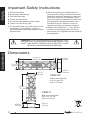
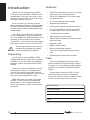
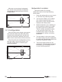
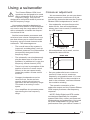
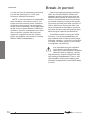
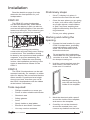
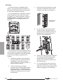
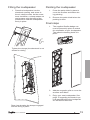
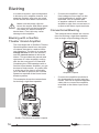
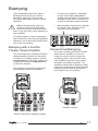
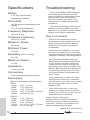
Cinema Ribbon
In-Wall Loudspeakers
CRW-3 and CRW-3C
CRW-3
CRW-3C
Installation Instructions and
User's Manual
Important Safety Instructions
Safety
1. Read Instructions.
2. Keep these Instructions.
3. Heed all Warnings.
4. Follow all Instructions.
5. Do not use this apparatus near water.
6. Clean only with a dry cloth.
7. Do not install near any heat sources such
as radiators, heat registers, stoves, or
other apparatus (including amplifiers) that
produce heat.
8. Refer all servicing to qualified service
personnel. Servicing is required when the
apparatus has been damaged in any way,
such as a connector is damaged, liquid
has been spilled or objects have fallen into
the apparatus, the apparatus has been
exposed to rain or moisture, does not
operate normally, or has been dropped.
9. Object and Liquid Entry — Care should
be taken so that objects do not fall into
and liquids are not spilled into the inside of
the apparatus.
WARNING: THIS LOUDSPEAKER IS CAPABLE OF PRODUCING VERY HIGH SOUND PRESSURE LEVELS. YOU
MUST TAKE EVERY PRECAUTION TO PROTECT YOUR
HEARING FROM PERMANENT DAMAGE.
Dimensions
Dimensions
32.50 in/
826 mm
3.64 in/
92 mm
7.72 in/
196 mm
7.87 in/
200 mm
4.05 in/
103 mm
CRW-3C
Wall cutout required:
6.4" H x 30.4" W
(163 x 772 mm)
28.0 in/
711 mm
CRW-3
Wall cutout required:
25.6" H x 6.5" W
(650 x 165 mm)
4.05 in/
103 mm
3.64 in/
92 mm
User's Manual
Introduction
Features
Contents
Location
Safety Instructions.............. 2
Dimensions........................ 2
Introduction........................ 4
Rear Panel Features.......... 6
Front Panel Features......... 7
Location............................. 8
Using a subwoofer........... 11
Break-in period................. 12
Installation........................ 13
Wiring........................... 14
Biwiring.......................... 16
Biamping....................... 17
Specifications................... 18
Troubleshooting............... 18
Limited Warranty.............. 19
Service Assistance........... 19
Installation
Biamp/wire
User's Manual
Misc.
For more information on this and other Sunfire
products, please visit our website:
www.sunfire.com
Introduction
Thank you for purchasing a Sunfire
XT-Series Cinema Ribbon CRW in-wall
loudspeaker. We hope you enjoy it and
the music it makes as much as we have
enjoyed creating it for you.
As an exclusive XT-Series product,
this loudspeaker follows a great heritage
of both world-class ribbon loudspeaker
designs and industry-leading subwoofer
technologies.
The CRW-3 and CRW-3C loudspeakers are designed as a perfect match to
our True Subwoofer and SubRosa series,
resulting in the ultimate home theater
experience... the kind of heart-felt experience that could only come from Sunfire.
The loudspeakers should only be
installed by qualified and experienced professional installers.
Unpacking
Your Sunfire Cinema Ribbon CRW
loudspeaker should reach you in perfect
condition. If you do notice any shipping
damage, please contact Sunfire immediately.
Gently lift out the loudspeaker and all
the packing material. It is important to
save all the packing materials and the
box in case your loudspeaker ever needs
to be moved or shipped for repair.
Make sure that you keep your sales
receipt. It is the only way to establish
the duration of your Limited Warranty
and it may come in useful for insurance
purposes.
Features
• CRW-3 loudspeaker for front, surround,
and back surround applications
• CRW-3C loudspeaker for center channel applications
•2 1/2 way, tapered array design
• Magnetically shielded
• Waveguide-loaded Neodymium ribbon
• 4.5-inch High Back-emf drivers (three
for the CRW-3, four for the CRW-3C)
• 117 dB maximum output
• 440 watts maximum power
• Stylish black anodized aluminum frame
with end caps
• Magnetic grille
• Ribbon level control
• Biwire and Biamp capable
• Two pairs of gold-plated spring terminals
• Optional pre-construction bracket
Care
If your loudspeaker needs servicing,
please read the Troubleshooting section
on page 18. If a problem persists, please
contact your nearest authorized Sunfire
Dealer.
Please take a moment to fill out and
mail the Sunfire Customer Response
card. Also read the serial number located
on the rear label and record it here:
Serial Number:
Purchased from:
Date:
User's Manual
Overview
CRW-3 loudspeaker
Ribbon CRW loudspeakers, you get the
same advantages: high output, small
size, high efficiency, and years of troublefree operation.
Conclusion
CRW-3C center loudspeaker
The Cinema Ribbon CRW-3 and the
CRW-3C are high performance loudspeakers that are specifically designed to
work with your flat panel display. Sharing
technology with the rest of the Cinema
Ribbon line, years of research and
decades of experience have gone into
these amazing loudspeakers.
The ribbon - a legacy refined
The ribbon in this loudspeaker is a remarkable piece of engineering, because
it has the output capability, purity, and
low distortion of a large 6-foot-tall ribbon
- in fact, it is derived from Bob Carver’s
award-winning Amazing Loudspeaker
from the late 1970s! The sound from the
CRW-3 ribbon is deliberately focused
in the forward direction, with very little
sound going up or down - reducing reflections off the ceiling and floor, that disturb
our sense of space and imaging. The
CRW-3C features an integrated “acoustic
lens,” that disperses the signal for center
channel applications.
The woofers - a legacy refined
Sunfire created the category of smallbox, high-power subwoofers more than
a decade ago with the original True
Subwoofer. This design relies on highpressure, “High Back-emf” technology
that provides very high bass output from
a very small box. When migrating this
subwoofer technology to the midrange
and high frequencies on the Cinema
User's Manual
The Cinema Ribbon CRW loudspeakers are a no-compromise answer to the
age-old question of Form vs. Function.
Why not get both? Combine these speakers with the SubRosa In-wall subwoofer
for the ultimate in hidden high performance.
Installation overview
A template is supplied to help mark
the sheetrock for cutting. A paint shield
is also supplied to aid in painting the
loudspeakers.
An optional pre-construction bracket
is available that will help you install the
loudspeakers in rooms that are under
construction. Please contact Sunfire to
order this bracket. (It comes with its own
installation guide.)
The CRW-3 may be mounted vertically
between wall studs, either side of your
big screen display.
The CRW-3C may be mounted horizontally, above or below your display. For
existing walls, the horizontal mounting
will involve cutting a vertical stud and
some extra framing.
The CRW-3C may also be used
vertically as left and right loudspeakers,
in which case, the acoustic lens can be
removed.
A system of six screw clamps secure
the loudspeaker firmly in place in the
sheetrock, once the opening has been
cut.
Rear Panel Features
1
2
3
CRW-3 Rear Connectors
1 3 2
CRW-3C Rear Connectors
1. Ribbon Binding Posts
5
4 5
3
Bridge Clips
5
2. Woofer Binding Posts
The loudspeakers have two sets of
binding posts that are joined with
bridge clips (3) for normal operation.
If the bridging clips are left in place,
then you can connect your amplifier
outputs to either positive/negative pair
of binding posts.
Always use high quality connections
and speaker wires, and make sure
there are no loose fittings or stray wire
strands. The spring connections accept
bare wire or pins.
Connect the positive speaker-level
output of your power amplifier or
receiver to a positive (red) input of the
loudspeaker. Connect the negative
speaker-level output of your power amplifier or receiver to a negative (black)
input of the loudspeaker.
Make sure that the positive and negative connections do not touch, or this
may damage your power amplifier.
Tighten all four adjacent nuts to make
sure the bridge clips are making good
contact.
3. Bridge Clips
From the factory, the two positive
binding posts are electrically joined
together with a bridge clip, as are the
two negative posts. Leave these clips
in place, unless you intend to biwire or
biamp your loudspeakers.
If the bridge clips are removed, the
loudspeaker can be biwired or
biamped. The ribbon posts (1) are then
used for connection of speaker-level
power to the ribbon section. The woofer
posts (2) are for connection of speakerlevel power to the woofer section.
(See page 16 and 17 for biamp/biwire
details.)
4. Speaker Wire Channel
To ease installation, the speaker wiring
can be passed through these channels
to the binding posts.
5. Clamps
Once the loudspeaker is pressed into
an opening in the sheetrock, screws
on the front panel are turned to pull the
clamps out and down to press against
the sheetrock, and secure the loudspeaker in place.
User's Manual
Front Panel Features
6
8
9
10
7
11
6. End Caps
These decorative end caps can be
painted to match your room decor. A
paint shield (13) is supplied to cover
the drivers during painting.
7. Ribbon Adjustment
This allows you to adjust the level of
the ribbon section relative to the other
drivers. The range of adjustment is ± 3 dB, and the default setting is in the
middle (0 dB). Perform a listening test
and adjust as desired.
8. Woofers
The CRW-3C uses four identical custom drivers. The CRW-3 uses 3.
9. Clamp Screws
These screws are used to clamp the
loudspeaker in place, once it has been
pressed into the sheetrock opening of
your wall.
10.Lens (CRW-3C only)
The CRW-3C uses an acoustic lens
over the ribbon to optimize the performance as a center loudspeaker.
User's Manual
12
13
11.Grille
The grille is attached to the main body
with magnets. To remove the grille,
gently pry it away from the corners.
12.Cutout Guide
This allows you to easily mark the
required cutout onto your wall.
13.Paint Shield
This covers the drivers and frame when
painting the end caps to match the
walls.
Loudspeaker Location
Center line
of display
Display
CRW-3
CRW-3
CRW-3C
(above or below display)
The CRW series loudspeakers are designed to be a perfect sound compliment
to flat panel displays. The CRW-3C center loudspeaker can be mounted above
or below the display, and the CRW-3 can
be mounted at either side.
The following details show various systems incorporating the loudspeakers, with
a subwoofer to handle the low frequency
range.
As with all loudspeaker installation,
check that the position does not
interfere with the picture quality.
Ideally, all of the surround loudspeakers in a home theater system should
be of the same make and model, and
positioned at similar heights to produce a
smooth and continuous soundfield. The
Cinema Ribbon Duos (CRM-2) use the
same drivers and ribbons as the CRW
series, making them perfect for rear
channel applications. Alternatively, you
could use CRW-3 loudspeakers.
Front Left/Right Speakers
The front left and right CRW-3
loudspeakers should be positioned so
that your TV display is exactly centered
between them. This will help focus your
attention towards the display.
Your left loudspeaker should be set
exactly the same distance and angle
away from your listening position as the
right loudspeaker.
Front left and right loudspeakers
If you have a smaller TV, the loudspeakers should be no more than two
feet away from the sides of the display.
User's Manual
If you have a Sunfire or Carver system
equipped with Sonic Holography, then
it is recommended that you use a tape
measure to set the left and right loudspeakers to be an equal distance away
from your listening position, within half
an inch tolerance. (Sonic Holography is a
unique process designed by Bob Carver
to enhance the three-dimensional effects
and realism of stereo sound.)
5.1 Configuration
Place each surround loudspeaker an
equal distance away from your central
listening position, and keep them at least
one or two feet above ear level (with you
sitting down).
The Center Loudspeaker
Most movie dialog will come from the
center loudspeaker, so careful positioning
is an important part of a good home theater system. Your eyes and ears should
focus your attention towards the center of
the display.
The CRW-3C center loudspeaker can
above, or directly underneath the display,
as long as it is located on the centerline
and not off to one side.
5.1 System
They can be placed behind the listening position, on the rear walls or the side
walls.
You can also experiment with “toeingin” the speakers slightly, to direct the high
frequencies to the listening position.
6.1 and 7.1 Configuration
Sunfire home theater processors and
receivers have two extra outputs for surround back loudspeakers. These create
a wonderful sense of realism in surround
effects during playback of Dolby Digital
EX, Dolby Pro Logic IIx, and DTS-ES.
Center loudspeaker
If possible, have the center, left and
right loudspeakers at the same height
(within two feet). This will help give a
smooth transition when sound effects
move from loudspeaker to loudspeaker.
We recommend that you keep the
CRW-3C grille on, as it is part of the
acoustic lens design of the center loudspeaker.
Such systems can be configured for
one or two surround back loudspeakers.
If you are connecting one surround
back loudspeaker, place it directly behind
your listening position and move the surround loudspeakers to the side as shown.
The CRM-2 ribbon loudspeakers may
be used as surround loudspeakers, as
shown in the following systems and illustrations. Alternatively, you can use the
CRW-3 in all surround locations.
6.1 System
User's Manual
With two surround back loudspeakers, set the surround back loudspeakers behind and between the surround
loudspeakers.
Subwoofer Location
The best location for a single
subwoofer can be found by following
these steps:
1. Place the subwoofer on your couch
or favorite easy-listening chair.
2. You can then either run a calibration (noise) signal through it, or
play some of your favorite music
samples with heavy bass.
7.1 System
9.1 Configuration
Some Sunfire home theater processors
and receivers have two side-axis channels that are matrixed from the left and
right front channels, and they are available in stereo as well as surround modes.
Place the side-axis loudspeakers along
the side walls, close to the fronts. You
can also angle them in towards your
listening position.
3. Walk around the room, standing in
all the positions where you might
be able to place the subwoofer.
This is usually somewhere close
to the corners of the room. Try
locations fairly close to the front
loudspeakers, and try crouching
down low.
4. Find the place in the room where
the bass output from the subwoofer
is most even. Shut things down and
install the subwoofer there.
5. This is the best position for the
subwoofer. The bass will sound the
best when you are sitting in your
normal listening position.
9.1 System
10
User's Manual
Using a subwoofer
The Cinema Ribbon CRW loudspeakers are designed to be used
with a subwoofer to fill in the lower
frequency range. They are not
designed to accept 400 watts of power at
the full frequency range.
Your system should be designed so
that the Cinema Ribbon CRW loudspeakers receive only the range above 80 Hz,
with a subwoofer to handle the frequencies below 80 Hz.
Crossover adjustment
We recommend that you set your home
theater processor's crossover to 80 Hz,
and set the channels that use the Cinema
Ribbon CRW loudspeakers to "small."
• Your subwoofer receives frequencies
below 80 Hz, from all loudspeakers
whose size is set to small, in addition to
the LFE channel:
Sunfire home theater processors and
receivers have a bass management system that allows you to redirect the bass
frequency range of each channel to the
subwoofer. The advantages are :
•
The overall bass of the system is
improved, as subwoofers, such as
Sunfire's powered True Subwoofers
are specially designed for this
frequency range.
•
The subwoofer can simultaneously
play the bass from all of the loudspeakers, in addition to it’s own low
frequency effects channel (LFE).
•
There is no loss in perception of the
position of movie or music sound
effects, as the ear cannot easily
locate the position of bass sound
sources.
•
•
Compact loudspeakers can be
used for front, center and surrounds, as they do not have to
reproduce the low frequency range.
This leads to a saving in room
space.
Your amplifiers do not waste power
reproducing the low frequency
range.
User's Manual
• All loudspeakers set to small, receive
frequencies above 80 Hz.
• Set your subwoofer's own crossover
control (if it has one) to maximum
frequency or bypassed mode. If it is set
lower than the 80 Hz, there would be a
hole in the mid-bass, and bass information would be missing.
The acoustic summation of the
subwoofer output and the Cinema Ribbon
CRW output produces a flat frequency
response.
NOTE: Dolby Digital and DTS modes
are designed especially for complete
systems with front, center, and surround
loudspeakers and subwoofers. You need
all of the loudspeakers to get the best
performance from your Home Theater. If
11
continued..
you do not have a subwoofer connected,
you will be missing the 5.1 LFE (low
frequency effects) information.
NOTE: If your processor or preamplifier
does not have a crossover control, you
might need an external active crossover
to split the audio signal into a low-pass
range for the subwoofer, and a high-pass
range for the Cinema Ribbon CRW loudspeakers. (Sunfire subwoofers have their
own crossover controls with line-level
high-pass outputs that can be used to
power an amplifier connected to Cinema
Ribbon CRW loudspeakers.)
Break-in period
Like many high performance automobiles, the Cinema Ribbon CRW loudspeakers perform at their best after an
initial break-in period. A minimum of 20
hours is recommended prior to performing critical listening, however the speakers will sound their best after a period of
300 to 400 hours. During this time, the
driver suspensions and ribbon structure
will relax into their operating design positions and give optimum performance.
To facilitate break-in during the initial
20 hours, it is recommended that you
play material with a wide dynamic range
at louder volumes – such as your favorite
rock and roll album (that is if your family
or neighbors can stand it).
It is important that your amplifier
must supply good clean power,
and not run into distortion. Amplifier
distortion due to clipping, causes
high-frequency output components that
can damage loudspeakers. Even a 100
watt amplifier running into clipping can
damage loudspeakers rated at 400 watts
or more.
12
User's Manual
Installation
Read the details on page 8 to help
determine the best position for your
loudspeakers.
CRW-3C
The CRW-3C center loudspeaker
can be fitted horizontally, either above
or below the display. A pair can also be
used as left/right speakers if the acoustic
lenses are removed. This is done by gently prying them off at the four corners.
Preliminary steps:
•
If the TV display is in place, it
should be removed from the wall.
•
Clear the area where you are going
to work, so it will be safe. Remove
any fragile objects, small children
or pets, and cover anything that
might be affected by dust from cutting sheetrock.
•
Put on your safety glasses.
Marking and cutting the
opening
Horizontal mounting into existing
construction will most likely mean cutting
a vertical stud. This installation should
be done by an experienced and qualified
carpenter, to prevent weakening the
wall structure. When the extra framing
is done, the installation and wiring is the
same as described as follows for the
CRW-3.
CRW-3
The CRW-3 loudspeakers can be wall
mounted vertically, for example, on either
side of a display. We recommend that the
ribbon section is positioned at a height
close to ear-level, therefore you can fit
the CRW-3 loudspeakers with the ribbon
at the bottom if necessary.
1. Choose the best location for your
CRW-3 loudspeakers, preferably
centered between vertical wall
studs. Use a stud finder to find
where the studs are.
Do not position the loudspeaker
closer than one inch from the cabinet sides to a stud. This allows for
the clamps to swing out.
2. Hold the cutout template onto the
wall surface, and use a level to
make sure it is vertical.
Marking the opening
onto the wall using the
inside of the template
Tools required:
•
Phillips screwdriver or screw gun
•
Pencil or other suitable wall marker
•
Sheetrock saw
•
Safety glasses
•
Level
•
Sturdy ladder or step ladder
•
Electronic stud finder if needed
•
You may need an assistant.
User's Manual
3. Mark the sheetrock with a pencil
around the inside of the template,
and remove the template.
4. Carefully cut out the sheetrock
around the marked lines, and
remove any debris from the hole.
13
Wiring
In normal wiring, the bridging clips
(item 3, on page 6) are left in place, so
the ribbon and the woofers are powered
by the same amplifier channel.
The front channels of Sunfire's Theater
Grand Amplifiers each have two pairs
of outputs. In a normal system, use the
voltage source. See page 16 for other
wiring options, including biamping, or
biwiring.
3. Pass the wiring through the wiring
channels in the back of the loudspeaker (see item 4 on page 6.)
Connecting
the wires
4. Do an electrical continuity test to
make sure the connections are
good from the amplifier-end of the
speaker wire to the ends of the
wires at the loudspeaker.
MINIMUM SPEAKER LOAD IMPED
ANCE 4 OHMS
This example shows the speaker wiring
connections for a right front speaker. On
conventional amplifiers, use the standard
positive and negative speaker-level
outputs.
1. Install the speaker wires following
all local codes for electrical wiring
installation. Use class 2 wiring,
and 12 gauge is recommended, 16
gauge is the minimum.
2. Follow common low voltage
practices like avoiding high voltage
electrical wiring, or crossing them
perpendicularly. This will reduce the
chance of picking up hum or other
interference.
14
5. Secure the wiring to the loudspeaker's spring-loaded binding posts,
observing the correct polarity.
Gently pull on them to make sure
they are secure.
6. It is a good idea to secure the wiring from vibration as much as possible. Do not have the weight of the
cables hanging on the terminals.
User's Manual
Fitting the loudspeaker
1. Press the loudspeaker into the
sheetrock opening, and screw in
the six clamp screws. As the screw
turns clockwise, a clamp rotates out
and presses onto the back of the
sheetrock to hold the loudspeaker
firmly in place.
Painting the loudspeaker
1. Press the paint shield in place to
cover the woofers and ribbon during painting.
2. Remove the paint shield when the
painting is done.
Final steps
1. The supplied Sunfire badge can
now be pressed in place to match
the orientation of your loudspeaker.
The adhesive backing holds it in
place
Tighten the clamps (the sheetrock is not
shown for clarity)
2. Add the magnetic grille to cover the
woofers and ribbon.
3. Enjoy your new loudspeaker. See
page 12 regarding the break-in period required before the loudspeakers will sound their best.
Rear view showing the clamps engaged
and the wiring in place
User's Manual
15
Biwiring
In a biwired system, each loudspeaker
is driven by one amplifier channel, but
separate speaker wire pairs are used
for the woofer and ribbon connections.
Make sure the bridge clips between the woofer and ribbon posts
are removed from the loudspeakers when you want to biamp or
biwire them. If not, this may cause
damage to the amplifier.
Biwiring with a Sunfire
Theater Grand Amplifier
The front channels of Sunfire's Theater
Grand Amplifiers each have two pairs
of outputs that can be used to biwire
your speakers. The idea is to use the
voltage source to drive the woofers,
and the current source to drive the
ribbon. This provides the warmth and
openness of a tube amplifier section,
with the low end punch of Class A/B.
Combining the CRW speakers with a
Sunfire home theater amplifier, you get
the best of both worlds - a system that
is at the top of its class in musicality,
yet is still able to produce the visceral
dynamics required of the finest home
theater systems.
This example shows the connections
for biwiring a right front speaker.
•
Connect the amplifier’s right
front voltage source output to the
right loudspeaker’s woofer input
terminals. Use a separate pair
of speaker cables to connect the
amplifier’s right front current source
output to the ribbon input terminals.
Conventional Biwiring
The example below shows the connections for biwiring a right front speaker
from a single output binding post pair.
MINIMUM SPEAKER LOAD IMPED
Amplifier outputs
•
ANCE 4 OHMS
Connect the amplifier terminals to
the loudspeaker's woofer input terminals, and use a separate speaker
cable pair to connect the amplifier
terminals to the ribbon input terminals.
Sunfire TGA Series Amplifier outputs
16
User's Manual
Biamping
The loudspeakers have two sets of
binding posts that can be used for
biwiring or biamping. These posts
are joined with bridge clips for normal
operation.
•
Connect the amplifier’s right back
output to the right loudspeaker’s
woofer input terminals. Connect the
amplifier’s right front current source
output to the ribbon input terminals.
Make sure the bridge clips are
removed from the loudspeakers
when you want to biamp or biwire
them. If not, this may cause damage to
your amplifier.
•
Both amplifier channels are fed with
the same (right, front) line-level
signal from your preamp.
In a biamp system, each loudspeaker
can be driven by two separate amplifier
channels; one to drive the woofers and
one to drive the ribbon.
Biamping with a Sunfire
Theater Grand Amplifier
The front channels of Sunfire's Theater
Grand Amplifiers each have two pairs
of outputs. In a biamp system, use the
current source to drive the ribbon and
a separate channel's voltage source
to drive the woofers.
This example shows the connections
for biamping a right front speaker.
MINIMUM SPEAKER LOAD IMPED
ANCE 4 OHMS
Conventional Biamping
If you are not using a Sunfire Theater
Grand Series amplifier (or you are
using the current source outputs for
something else), then connect separate amplifier channels to the woofer
terminals and ribbon terminals. The
amplifiers should be of identical power
output and performance. Both amplifier
channels are fed with the same linelevel signal from your preamp.
MINIMUM SPEAKER LOAD IMPED
ANCE 4 OHMS
Amplifier outputs
MINIMUM SPEAKER LOAD IMPED
ANCE 4 OHMS
Sunfire TGA Series Amplifier outputs
User's Manual
17
Specifications
Troubleshooting
Design
The Cinema Ribbon CRW loudspeakers are designed and built to provide
years of trouble-free performance. Most
problems that occur can usually be
solved by checking your setup, or by
making sure all components are fully
operational.
2 1/2 way, Tapered Array
Magnetically Shielded
Drive Units
HF: Waveguide loaded Neodymium
Ribbon
LF: 4.5-inch High Back-emf
The following information will help you
deal with common problems you may
experience. If a problem persists, please
contact your Dealer for assistance.
Frequency Response
80 Hz to 40 kHz
Crossover Frequency
250 Hz to 1.5 kHz
Poor or no sound
•
Check all the connections from the
loudspeaker to the amplifier or receiver.
Swap loudspeakers around, and see
if the poor sound follows a particular
loudspeaker.
•
Check that your amplifier is not driven
too hard or is clipping. Even a low-powered amp driven into clipping can cause
distortion or damage your loudspeakers.
•
Many processor/preamps can send
test tones through all the loudspeakers
in your system. Use this to adjust the
volume of each channel until they are
all playing at the same level. Make sure
that any bass management options are
set correctly, and any channels using
the Cinema Ribbon loudspeakers are
set to "small."
•
If the system bass is weak only when
playing surround sources, check that
your processor is correctly set to decode
the surround modes, such as Dolby
Digital or DTS.
•
Some DVD discs have a menu that
allows you to select which soundtrack
to play. Check that the correct surround
audio soundtrack is selected.
Maximum Power
440 watts
Minimum Power
25 watts
Sensitivity (2.83 V/1 meter)
89.5 dB
Maximum Output
117 dB
Impedance
6 ohms nominal
Connections
2 pairs gold plated spring terminals
Dimensions
(Maximum dimensions, including grille)
CRW-3
Height
28.0" (711 mm)
Width
7.87" (200 mm)
Depth
4.05" (103 mm)
Cutout
25.6" x 6.5" (650 x 165 mm)
Weight
19.2 lbs (8.7 kg)
CRW-3C
Height
Width
Depth
Cutout
Weight
7.72" (196 mm)
32.50" (826 mm)
4.05" (103 mm)
6.4" x 30.4" (163 x 772 mm)
24.3 lbs (11 kg)
© 2008 Sunfire Corporation.
All rights reserved. Sunfire Corporation
reserves the right to improve its products
at any time. Therefore, specifications are
subject to change without notice.
Manual 913-145-00 Rev B
18
User's Manual
Limited Warranty
Sunfire Corporation is proud of its
products which have been built with care
using advanced technology and premium
component parts. Your unit has been
crafted to perform properly for many
years. Sunfire Corporation offers the
following Warranty to you, the owner of a
new Sunfire product:
The Sunfire Corporation Warranty for
the XT-Series Cinema Ribbon CRW
loudspeaker is in effect for FIVE years
from the date of original retail purchase.
The Sunfire Corporation Warranty covers
defects in materials and workmanship.
The following, however, are excluded:
Some states do not allow limitations on
how long an implied warranty lasts and/or
do not allow the exclusion or limitation of
incidental or consequential damages, so
the above limitations or exclusions may not
apply to you.
This Warranty gives you specific legal
rights, and you may also have other
rights which vary from state to state. We
suggest that you attach your purchase
receipt to this Warranty and keep these in
a safe place. Thank you for your choice
of a Sunfire Corporation product.
Service Assistance
a) Damage caused during shipment.
We suggest that you read the Limited
Warranty completely to fully understand
your Warranty/Service coverage.
b) Damage caused by accident, misuse, abuse of operation contrary
to the instructions specified in the
Sunfire Corporation user’s manual
If your Sunfire Corporation product ever
requires service, write to us, or call:
Sunfire Corporation
Technical Services Department
P.O. Box 1589
Snohomish, WA 98290
[email protected]
Tel (425) 335-4748
Fax (425) 335-4746
c) Units where the serial number
has been defaced, modified or
removed,
d) Damage resulting from modification
or attempted repair by any person
not authorized in writing by Sunfire
Corporation.
e) Units purchased from unauthorized
dealers.
You will be directed to an authorized
Sunfire Corporation Service Station or
receive instructions to ship the unit to the
factory. Please save the original shipping
carton and packing materials in case
shipping is required. Please do not ship
Parcel Post.
The Sunfire Corporation Warranty extends to the original owner during the five
year warranty period so long as the original dated purchase receipt is presented
whenever warranty service is required.
All implied warranties, including warranties or merchantability and fitness
for particular purposes, are limited in
duration to the five year length of this
Warranty, unless otherwise provided by
state law.
Sunfire Corporation’s liability is limited
to the repair or replacement, at our option, of any defective product and shall
not in any event include property or any
other incidental or consequential damages which may result from the failure of
this product.
User's Manual
NOTE: Before sending in your unit for repair, you must call Sunfire for return authorization (RA).
Include a complete description of the
problem, indicating how you have it
connected, the associated equipment in
your system and a copy of your purchase
receipt. Initial shipping costs are not paid
by Sunfire Corporation; return ground
shipping costs will be prepaid if repairs
were covered by the scope of this Warranty.
19
Cinema Ribbon
In-Wall Loudspeakers
CRW-3 and CRW-3C
Manual 913-145-00 Rev B