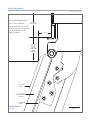
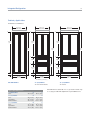
1
SUB-ZERO DESIGN GUIDE
Contents
Built-In Refrigeration . . . . . . . . . . . . . . . . . . . . . . . . . . 3
PRO 48 Refrigeration . . . . . . . . . . . . . . . . . . . . . . . . . 44
Integrated Refrigeration . . . . . . . . . . . . . . . . . . . . . . 50
Wine Storage . . . . . . . . . . . . . . . . . . . . . . . . . . . . . . . 64
Undercounter Refrigeration . . . . . . . . . . . . . . . . . . . . 84
Sub-Zero Warranties . . . . . . . . . . . . . . . . . . . . . . . . . 92
MODELS BI-36RG AND BI-36F
Features and specifications are subject to change at any
time without notice. Visit subzero.com/specs for the most
up-to-date information.
IMPORTANT NOTE: Throughout this guide, dimensions in
parentheses are millimeters unless otherwise specified.
Built-In Refrigeration
3
subzero.com/specs
Built-In Refrigeration. For the built-in line, Sub-Zero designers and engineers took a fresh look at everything, inside
and out. Exterior refinements include redesigned grilles and lower-profile hinges. Inside, new technology in food preservation makes the built-in line nothing short of revolutionary.
BUILT-IN MODELS
36"
36"
36"
(914)
(914)
(914)
84"
84"
(2134)
(2134)
BI-36R
BI-36RG
BI-36F
30"
30"
36"
36"
(762)
(762)
(914)
(914)
BI-30U
BI-30UG
BI-36U
36"
42"
42"
48"
48"
(914)
(1067)
(1067)
(1219)
(1219)
BI-36UG
84"
(2134)
BI-36S
BI-42S
BI-42SD
BI-48S
BI-48SD
KEY FEATURES
• Four distinct design approaches: framed, overlay,
flush inset and stainless steel.
• Handle options coordinate with handles of Wolf
cooking products.
• Dual refrigeration; two compressors preserve food’s
goodness in two sealed compartments.
• Energy efficient; many models are ENERGY STAR®
qualified.
• Advanced water filtration and air purification systems.
• Crisper and deli drawers form a lower-temperature
zone for produce and meats.
• Flip-up grille provides easy access for quick routine
maintenance.
• All models are Star-K certified.
Built-In Refrigeration
4
Built-In Design Options. A design classic is now even better. Four distinct design approaches provide limitless
flexibility for creating a beautiful kitchen. Lower-profile hinges enable the built-in units to blend more seamlessly with
surrounding cabinetry.
Framed. Custom cabinetry
Overlay. Custom cabinet
panels slide into the door to
blend into the kitchen design.
Shown with full-length handle
and louvered grille option for
the traditional Sub-Zero look.
overlay panels can be
combined with unique
hardware for design flexibility.
Shown with pro handle option
to complement Wolf ranges.
Built-In Refrigeration
5
subzero.com/specs
Flush Inset. This design
option allows for a flush door
and grille. Stainless steel panels
are available as sales accessories. Shown with tubular
handle option to mirror Wolf
built-in ovens.
Stainless Steel. For a
professional look, this design
requires no customization. To
complement the look of Wolf
ranges, choose the pro handle
option shown here.
Built-In Refrigeration
6
Built-In Models
All Refrigerator / All Freezer Models
SPECIFICATIONS
OVERALL DIMENSIONS
Interior Capacity
R cu ft (L)
F cu ft (L)
36" (914)
24" (610)
ALL REFRIGERATOR / ALL FREEZER MODELS
BI-36R
BI-36RG
BI-36F
23.4 (663)
23.2 (657)
22.8 (646)
OVER-AND-UNDER MODELS
BI-30U
BI-30UG
BI-36U
BI-36UG
13.0 (368)
13.0 (368)
16.2 (459)
16.1 (456)
4.1 (116)
4.1 (116)
5.3 (150)
5.3 ( 150)
84"
(2134)
73 3/4"
SIDE-BY-SIDE MODELS
BI-36S
BI-42S
BI-42SD
BI-48S
BI-48SD
(1873)
12.2 (346)
16.1 (456)
16.0 (453)
18.8 (532)
18.7 (530)
Shipping Weight
8.0 (227)
8.0 (227)
8.1 (230)
9.5 (269)
9.7 (265)
lbs (kg)
ALL REFRIGERATOR / ALL FREEZER MODELS
BI-36R
BI-36RG
BI-36F
420 (191)
430 (195)
406 (184)
HEIGHT DIMENSIONS ± 1/2" (13)
4" (102)
23 7/8" (606)
OVER-AND-UNDER MODELS
BI-30U
BI-30UG
BI-36U
BI-36UG
462 (210)
476 (216)
515 (234)
529 (240)
23 7/8"
(606)
17"
(432)
SIDE-BY-SIDE MODELS
BI-36S
BI-42S
BI-42SD
BI-48S
BI-48SD
538 (244)
582 (264)
608 (276)
630 (286)
656 (298)
37 1/4"
(946)
2 3/8" (60)
MODELS BI-36R, BI-36RG AND BI-36F
Shipping weights and overall dimensions are based on
stainless steel models. For flush inset applications, add
1/2" (13) to door clearance dimensions.
Built-In Refrigeration
7
subzero.com/specs
Over-and-Under Models
OVERALL DIMENSIONS
30" (762)
24" (610)
36" (914)
24" (610)
84"
84"
(2134)
(2134)
50 3/4"
50 3/4"
(1289)
(1289)
23"
23"
(584)
(584)
HEIGHT DIMENSIONS ± 1/2" (13)
4" (102)
HEIGHT DIMENSIONS ± 1/2" (13)
23 7/8" (606)
23 7/8"
23 7/8"
(606)
(606)
4" (102)
14 1/2"
17"
(368)
(432)
23 5/8"
(600)
311/4"
(796)
23 5/8"
(600)
37 1/4"
(946)
2 3/8" (60)
2 3/8" (60)
MODELS BI-30U AND BI-30UG
MODELS BI-36U AND BI-36UG
23 7/8" (606)
Built-In Refrigeration
8
Side-by-Side Models
OVERALL DIMENSIONS
36" (914)
24" (610)
42" (1067)
24" (610)
84"
84"
(2134)
(2134)
73 3/4"
73 3/4"
(1873)
(1873)
HEIGHT DIMENSIONS ± 1/2" (13)
4" (102)
HEIGHT DIMENSIONS ± 1/2" (13)
23 7/8" (606)
4" (102)
23 7/8"
23 7/8"
(606)
(606)
81/2"
101/4"
8 3/4"
12 1/2"
(216)
(260)
(222)
(318)
221/4"
26 1/4"
(565)
(668)
2 3/8" (60)
2 3/8" (60)
MODEL BI-36S
Overall dimensions are based on stainless steel models.
For flush inset applications, add 1/2" (13) to door clearance
dimensions.
MODELS BI-42S AND BI-42SD
23 7/8" (606)
Built-In Refrigeration
9
subzero.com/specs
Side-by-Side Models
OVERALL DIMENSIONS
48" (1219)
24" (610)
84"
(2134)
73 3/4"
(1873)
HEIGHT DIMENSIONS ± 1/2" (13)
4" (102)
23 7/8"
(606)
9 3/4"
14"
(248)
(356)
30"
(762)
2 3/8" (60)
MODELS BI-48S AND BI-48SD
23 7/8" (606)
Built-In Refrigeration
10
Built-In Models
STANDARD INSTALLATION
TOP VIEW
24" (610)
OPENING
DEPTH
UNIT WITH
3/4" (19) PANEL
24" (610)
OPENING DEPTH
83 3/4"
A
(2127)
OPENING
HEIGHT
OPENING WIDTH
SIDE VIEW
FRONT VIEW
BI-36R, BI-36RG and BI-36F
35 1/2" (902)
IMPORTANT NOTE: If two units are installed side by side,
refer to pages 30–31 for dual standard installations.
BI-30U and BI-30UG
29 1/2" (746)
Stainless steel models are ready to install out of the box.
BI-36U and BI-36UG
35 1/2" (902)
BI-36S
35 1/2" (902)
Opening Width
A
BI-42S and BI-42SD
411/2" (1054)
BI-48S and BI-48SD
47 1/2" (1206)
Built-In Refrigeration
11
subzero.com/specs
Planning Information
ELECTRICAL REQUIREMENTS
PLUMBING REQUIREMENTS
For all built-in models, the electrical supply should be
located within the shaded area shown in the illustration.
Follow the National Electrical Code and local codes and
ordinances when installing the receptacle. A separate
circuit servicing only this appliance is required. A ground
fault circuit interrupter (GFCI) is not recommended and
may cause interruption of operation.
All built-in models with an automatic ice maker come with
a microbiological water filtration system. The water supply
line should be located within the shaded area shown in the
illustrations. The water supply line should be connected to
the house supply with an easily accessible shut-off valve
between the supply and the unit. Do not use self-piercing
valves. A saddle valve kit (4200880) is available through
your authorized Sub-Zero dealer. The water line must not
interfere with installation of the anti-tip brackets.
Electrical Requirements
Power Supply
115 V AC, 60 Hz
Circuit Breaker
15 amp
Receptacle
3-prong grounding-type
FRONT VIEW
7"
(178)
IMPORTANT NOTE: A reverse osmosis system can be
used provided there is constant water pressure of 30 psi
(2.1 bar) to 100 psi (6.9 bar) supplied to the unit at all
times. In this application, the microbiological water filtration system should be set to bypass mode by removing
the water filter cartridge and inserting the bypass plug
(7005018) available through your authorized Sub-Zero
dealer. Installation instructions packed with the unit will
outline this procedure.
E
6"
(152)
Plumbing Requirements
1/4"
Water Supply Line
Water Pressure
75 1/2"
(1918)
FROM
FLOOR
OD copper line
30–100 psi (2.1–6.9 bar)
Excess Water Line for Connection
36" (914)
Location of electrical supply.
BACK WALL
18" (457)
18" (457)
1/2"
(13)
6"
(152)
6"
(152)
3" (76)
FLOOR
FRONT VIEW
Location of water supply—
rear.
TOP VIEW
Location of water supply—
bottom.
Built-In Refrigeration
12
Framed Application
IMPORTANT NOTE: The framed application is not a
separate model. This is an overlay unit in a framed application.
The framed panel design option is available for all built-in
overlay models. You must specify panels, full-length
handles and a framed grille insert to achieve the traditional
framed look. For exact door panel dimensions refer to
framed panel specifications on the following pages. Also
refer to the full-scale templates at the end of this section
for additional panel and handle considerations.
Optional extended full-length handles that provide additional finger clearance for raised panels are available
through your authorized Sub-Zero dealer.
Custom cabinetry panels slide into the door to blend into the
kitchen design. Shown with full-length handle and louvered
grille option for the traditional Sub-Zero look.
Framed Panel Requirements
MAX WEIGHT PER PANEL
BI-36R, BI-36RG and BI-36F
All Other Framed Panels
75 lbs (34 kg)
50 lbs (23 kg)
MIN PANEL THICKNESS
All Framed Panels
1/4"
(6)
Built-In Refrigeration
13
subzero.com/specs
Framed Panels
If the thickness of the custom panels is less than 1/4" (6),
they must be backed up with a sheet of shim material to
build the total thickness to 1/4" (6). If the panel is thicker
than 1/4" (6), a routed edge must be provided around the
panel to ensure a proper fit. Refer to the illustrations.
IMPORTANT NOTE: For framed design applications,
routing, recessing or optional extended handles may be
required on raised panels for finger clearance under the
handle. Refer to the full-scale templates at the end of this
section.
IMPORTANT NOTE: Do not cover a glass door with a solid
panel. Also, the edges of the window cut-out will need to
be finished, as they will be exposed.
IMPORTANT NOTE: When installing two units in a side-byside application, refer to pages 30–31 for dual standard
installations. Be aware that rough opening dimensions are
different for this application.
TRIM
REVEAL
1/4" (6) min
1/4" (6)
MAIN FRAME
DOOR
TRIM
REVEAL
1/4" (6) min
ROUT TO
1/4" (6)
MAIN FRAME
DOOR
PANEL
Panels 1/4" (6) thick or less.
Panels thicker than 1/4" (6).
Built-In Refrigeration
14
Framed Panels
A
H
A
A
A
H
H
A
A
H
A
H
H
B
W
BI-36R / BI-36F
W
W
BI-36RG
BI-30U / BI-36U
Models BI-36R, BI-36RG and BI-36F
REFRIGERATOR/FREEZER
Door Panel
BI-36RG
W
BI-30UG / BI-36UG
Models BI-30U and BI-30UG
W
H
35 3/4" (908)
69 9/16" (1767)
W
H
Window Cut-Out
25 1/2" (648)
54 1/16" (1373)
A
B
Cut-Out Location
5 3/16" (132)
10 5/16" (262)
REFRIGERATOR
Door Panel
FREEZER
Drawer Panel
BI-30UG
Window Cut-Out
W
H
29 3/4" (756)
49 15/16" (1268)
W
H
29 3/4" (756)
18 11/16" (475)
W
H
19 1/2" (495)
39 11/16" (1008)
A
5 3/16" (132)
Cut-Out Location
Models BI-36U and BI-36UG
REFRIGERATOR
Door Panel
FREEZER
Drawer Panel
BI-36UG
Window Cut-Out
W
H
35 3/4" (908)
49 15/16" (1268)
W
H
35 3/4" (908)
18 11/16" (475)
W
H
25 1/2" (648)
39 11/16" (1008)
A
Cut-Out Location
5 3/16" (132)
Built-In Refrigeration
15
subzero.com/specs
Framed Panels
H
H
A
B
W
W
BI-36S / BI-42S / BI-48S
W
W
BI-42SD / BI-48SD
Model BI-36S
REFRIGERATOR
Door Panel
FREEZER
Door Panel
Models BI-48S and BI-48SD
W
H
19 13/16" (503)
69 9/16" (1767)
W
H
15 7/16" (392)
69 9/16" (1767)
REFRIGERATOR
Door Panel
FREEZER
Door Panel
BI-48SD
Dispenser Cut-Out
Models BI-42S and BI-42SD
REFRIGERATOR
Door Panel
FREEZER
Door Panel
BI-42SD
Dispenser Cut-Out
Cut-Out Location
W
H
24 13/16" (630)
69 9/16" (1767)
W
H
16 7/16" (418)
69 9/16" (1767)
W
H
5 7/8" (149)
12 7/16" (316)
A
B
1 7/8" (48)
28 3/4" (730)
Cut-Out Location
W
H
28 1/2" (724)
69 9/16" (1767)
W
H
18 3/4" (476)
69 9/16" (1767)
W
H
5 7/8" (149)
12 7/16" (316)
A
B
1 7/8" (48)
28 3/4" (730)
For models BI-42SD and BI-48SD, panel thickness in the
dispenser area can range from 1/4" (6) to a maximum of
1 1/8" (29). If the panel is thicker, you must rout out a minimum
1/4" (6) flat landing area to accommodate the glasswell bezel.
Built-In Refrigeration
16
Framed Application
OPTIONAL GRILLE PANEL
A panel grille, providing an 84" (2134) finished height, is
standard on overlay models. Optional panel grilles are
available for 83" (2108) and 88" (2235) finished heights.
Grille panel dimensions listed are for a standard 84" (2134)
finished height. For an 83" (2108) finished height, subtract
1" (25) from grille panel height dimensions. For an 88"
(2235) finished height, add 4" (102) to height dimensions.
Optional Grille Panel
W
H
30" (762) Models
29 3/4"
36" (914) Models
35 3/4" (908)
8 15/16" (227)
42" (1067) Models
41 3/4" (1060)
8 15/16" (227)
48" (1219) Models
47 3/4"
8 15/16" (227)
(756)
(1213)
8 15/16"
(227)
Grille Panel Requirements
MAX WEIGHT
Grille Panel
13 lbs (6 kg)
MIN PANEL THICKNESS
Grille Panel
1/4"
(6)
Optional grille panel.
Built-In Refrigeration
17
subzero.com/specs
Framed Application
PARTIAL FRAMED OPTION
If you choose not to use custom panels above and below
the glasswell for dispenser model BI-42SD or BI-48SD, a
stainless steel insert panel is available as a sales accessory. This accessory kit includes partial framed molding
and stainless steel panel to provide a spill-resistant finish
above and below the glasswell on the refrigerator door
only. The partial framed accessory kit (7004855) is
available through your authorized Sub-Zero dealer. Refer
to panel dimensions for the partial framed option below.
IMPORTANT NOTE: When using raised panels with the
partial framed kit, a 1/2" (13) trim reveal down to 1/4" (6)
thickness is necessary at the bezel for the panels to fit
properly.
Refrigerator Panel
Freezer Panel
BI-48SD
Refrigerator Panel
Freezer Panel
W
Partial framed kit.
Optional Partial Framed Panels
BI-42SD
H
W
H
15 1/16" (383)
16 7/16" (418)
69 9/16" (1767)
69 9/16" (1767)
W
H
16 3/4" (425)
18 3/4" (476)
69 9/16" (1767)
69 9/16" (1767)
W
BI-42SD / BI-48SD
Partial framed option.
Built-In Refrigeration
18
Overlay Panels
If you and your client have ordered an overlay model, you
will be adding panels and handles to give the unit a more
custom look. The overlay panel design option is available
for all built-in overlay models. For exact door panel dimensions, refer to overlay panel specifications on the following
pages.
IMPORTANT NOTE: Overlay models can be used in an
overlay or a flush inset application. Be aware that the
application specified will affect panel sizes, rough opening
dimensions and installation.
The overlay design allows decorative panels to cover the
door trim for a more seamless appearance that blends
with the design of the room. The most common way to
achieve this look is to work with three panels—the decorative overlay panel, which is typically 3/4" (19), a .10" (3)
spacer panel and a 1/4" (6) backer panel. Depending on
your cabinet manufacturer, this could also be one panel
routed for different dimensions.
Regardless of the physical construction of the panels
(three-panel assembly or routed panel), you will need to
follow the overlay panel specifications on the following
pages for exact sizing and panel placement to ensure a
proper fit.
Custom cabinet overlay panels can be combined with unique
hardware for design flexibility. Shown with pro handle option
to complement Wolf ranges and rangetops.
Overlay Panel Requirements
MAX WEIGHT PER PANEL
BI-36R, BI-36RG and BI-36F
All Other Overlay Models
Grille Panel
75 lbs (34 kg)
50 lbs (23 kg)
13 lbs (6 kg)
MIN PANEL THICKNESS
All Overlay Panels
5/8"
(16)
Built-In Refrigeration
19
subzero.com/specs
Overlay Panels
The illustrations provide a cross section view of the threepanel assembly, showing placement of the trim and a rear
view of the three-panel assembly with critical dimensions,
standard for all built-in models.
IMPORTANT NOTE: When installing two units in a side-byside application, refer to pages 30–31 for dual standard
installations. Be aware that rough opening dimensions are
different for this application.
Do not exceed overlay panel dimensions, as this could
cause damage to panels and the Sub-Zero unit.
SPACER
PANEL
OVERLAY PANEL
Overlay grille panels for the panel grille match the design
of the overlay door panels. Dimensions for the grille panel
are listed in the overlay panel specifications on the following pages.
IMPORTANT NOTE: On glass door models, the edges of
the overlay, spacer and backer panels of the window
cut-out will need to be finished, as they will be exposed.
OVERLAY
PANEL
SPACER PANEL
BACKER PANEL
BACKER
PANEL
TRIM
5/16" (8) min
1/8"
(3)
3/4"
(19)
typical
.10" (3) 1/4" (6)
Panel assembly cross section. Panel assembly rear view.
Built-In Refrigeration
20
Overlay Panels
H
H
H
H
A
H
A
A
A
H
H
A
A
H
A
H
H
B
W
BI-36R / BI-36F
W
W
BI-30U / BI-36U
BI-36RG
Models BI-36R, BI-36RG and BI-36F
REFRIGERATOR / FREEZER
Overlay Panel
Spacer Panel
Backer Panel
GRILLE
Overlay Panel
Spacer Panel
Backer Panel
BI-36RG
H
36" (914)
35 1/8" (892)
35 3/4" (908)
69 3/4" (1772)
68 15/16" (1751)
69 9/16" (1767)
W
H
36" (914)
35 1/8" (892)
35 3/4" (908)
9 1/4" (235)*
8 5/16" (211)
8 15/16" (227)
W
H
25 1/2" (648)
54 1/8" (1375)
A
B
Cut-Out Location
5 1/4" (133)
10 3/8" (264)
REFRIGERATOR
Overlay Panel
Spacer Panel
Backer Panel
FREEZER
Overlay Panel
Spacer Panel
Backer Panel
GRILLE
Overlay Panel
Spacer Panel
Backer Panel
BI-36UG
Window Cut-Out
Models BI-30U and BI-30UG
Overlay Panel
Spacer Panel
Backer Panel
FREEZER
Overlay Panel
Spacer Panel
Backer Panel
GRILLE
Overlay Panel
Spacer Panel
Backer Panel
BI-30UG
Window Cut-Out
W
H
36" (914)
35 1/8" (892)
35 3/4" (908)
50 1/8" (1273)
49 5/16" (1253)
49 15/16" (1268)
W
H
36" (914)
35 1/8" (892)
35 3/4" (908)
19" (483)
18 1/16" (459)
18 11/16" (475)
W
H
36" (914)
35 1/8" (892)
35 3/4" (908)
9 1/4" (235)*
8 5/16" (211)
8 15/16" (227)
W
H
25 1/2" (648)
39 5/8" (1006)
A
W
H
30" (762)
29 1/8" (740)
29 3/4" (756)
50 1/8" (1273)
49 5/16" (1253)
49 15/16" (1268)
W
H
30" (762)
29 1/8" (740)
29 3/4" (756)
19" (483)
18 1/16" (459)
18 11/16" (475)
W
H
30" (762)
29 1/8" (740)
29 3/4" (756)
9 1/4" (235)*
8 5/16" (211)
8 15/16" (227)
W
H
19 1/2" (495)
39 5/8" (1006)
A
Cut-Out Location
BI-30UG / BI-36UG
Models BI-36U and BI-36UG
W
Window Cut-Out
REFRIGERATOR
W
5 1/4" (133)
Cut-Out Location
5 1/4" (133)
*Panel height may be increased by 1/2" (13) to hide upper
main frame. For more information, refer to the built-in panel
configurator at subzero.com/trade/panels.
Grille panel dimensions listed are for a standard 84" (2134)
finished height. For an 83" (2108) finished height, subtract 1"
(25) from grille panel height dimensions. For an 88" (2235)
finished height, add 4" (102) to height dimensions. An 83"
(2108) or 88" (2235) panel grille must be ordered to accept an
83" (2108) or 88" (2235) custom panel. Width dimensions do
not vary.
Built-In Refrigeration
21
subzero.com/specs
Overlay Panels
H
H
H
H
A
B
W
W
BI-36S / BI-42S / BI-48S
W
W
BI-42SD / BI-48SD
Model BI-36S
REFRIGERATOR
Overlay Panel
Spacer Panel
Backer Panel
FREEZER
Overlay Panel
Spacer Panel
Backer Panel
GRILLE
Overlay Panel
Spacer Panel
Backer Panel
Models BI-48S and BI-48SD
W
H
20 1/16" (510)
19 3/16" (487)
19 13/16" (503)
69 3/4" (1772)
68 15/16" (1751)
69 9/16" (1767)
W
H
15 11/16" (398)
14 13/16" (376)
15 7/16" (392)
69 3/4" (1772)
68 15/16" (1751)
69 9/16" (1767)
W
H
36" (914)
35 1/8" (892)
35 3/4" (908)
9 1/4" (235)*
8 5/16" (211)
8 15/16" (227)
REFRIGERATOR
Overlay Panel
Spacer Panel
Backer Panel
FREEZER
Overlay Panel
Spacer Panel
Backer Panel
GRILLE
Overlay Panel
Spacer Panel
Backer Panel
BI-48SD
Dispenser Cut-Out
Models BI-42S and BI-42SD
REFRIGERATOR
Overlay Panel
Spacer Panel
Backer Panel
FREEZER
Overlay Panel
Spacer Panel
Backer Panel
GRILLE
Overlay Panel
Spacer Panel
Backer Panel
BI-42SD
Dispenser Cut-Out
Cut-Out Location
W
H
25 1/16" (637)
24 3/16" (614)
24 13/16" (630)
69 3/4" (1772)
68 15/16" (1751)
69 9/16" (1767)
W
H
16 11/16" (424)
15 13/16" (402)
16 7/16" (418)
69 3/4" (1772)
68 15/16" (1751)
69 9/16" (1767)
W
H
42" (1067)
41 1/8" (1045)
41 3/4" (1060)
9 1/4" (235)*
8 5/16" (211)
8 15/16" (227)
W
H
5 7/8" (149)
12 7/16" (316)
A
B
2" (51)
28 13/16" (732)
Cut-Out Location
W
H
28 3/4" (730)
27 7/8" (708)
28 1/2" (724)
69 3/4" (1772)
68 15/16" (1751)
69 9/16" (1767)
W
H
19" (483)
18 1/8" (460)
18 3/4" (476)
69 3/4" (1772)
68 15/16" (1751)
69 9/16" (1767)
W
H
48" (1219)
47 1/8" (1197)
47 3/4" (1213)
9 1/4" (235)*
8 5/16" (211)
8 15/16" (227)
W
H
5 7/8" (149)
12 7/16" (316)
A
B
2" (51)
28 13/16" (732)
*Panel height may be increased by 1/2" (13) to hide upper
main frame. For more information, refer to the built-in panel
configurator at subzero.com/trade/panels.
Grille panel dimensions listed are for a standard 84" (2134)
finished height. For an 83" (2108) finished height, subtract 1"
(25) from grille panel height dimensions. For an 88" (2235)
finished height, add 4" (102) to height dimensions. An 83"
(2108) or 88" (2235) panel grille must be ordered to accept an
83" (2108) or 88" (2235) custom panel. Width dimensions do
not vary.
Built-In Refrigeration
22
Flush Inset Application
It is necessary to consider the following points when
planning for a flush inset application:
• The flush inset depth is 2 3/16" (56) deeper than the
standard opening.
• The flush inset width is 2 1/2" (64) wider than the
standard opening.
• The flush inset height is 1/4" (6) higher than the
standard opening.
• Panel widths increase to achieve the flush inset look.
• You must allow a 1/2" (13) reveal around the perimeter
of the unit and grille to allow for proper door swing and
airflow.
IMPORTANT NOTE: The flush inset application is not a
separate model. This is an overlay unit in a flush installation. The same model is used in an overlay or flush inset
application.
Rough opening dimensions for the flush inset application
assume the use of a 3/4" (19) decorative panel. The
illustrations below show the difference between standard
and flush inset installations.
This design option allows for a flush door and grille. Stainless
steel panels are available as sales accessories. Shown with
tubular handle option to mirror Wolf
built-in ovens.
STANDARD INSTALLATION
24" (610)
OPENING
DEPTH
FLUSH INSET INSTALLATION
WITH 3/4" (19) PANEL
26 3/16"
24" (610)
OPENING
DEPTH
TOP VIEW
Standard installation.
(665)
FLUSH
INSET
DEPTH
TOP VIEW
2 3/16"
11/4"
(56)
(32)
Flush inset installation.
Built-In Refrigeration
23
subzero.com/specs
Built-In Models
FLUSH INSET INSTALLATION
TOP VIEW
26 3/16"
24" (610)
DEPTH
(665)
FLUSH TO CLEAT
INSET
DEPTH
11/4"
(32)
UNIT WITH
3/4" (19) PANEL
CLEAT
26 3/16" 24" (610)
TOP VIEW
(665)
OPENING
FLUSH
DEPTH
INSET TO CLEAT
DEPTH
CLEAT
3" (76)
typical
DETAIL A
2 3/16" (56)
2 3/16"
1/4"
(6)
(56)
11/4"
(32)
CLEAT
24" (610)
DEPTH TO CLEAT
Detail A
2 3/16"
(56)
26 3/16" (665)
FLUSH INSET DEPTH
3" typical
(76)
CLEAT
4" (102)
83 3/4"
(2127)
HEIGHT
TO CLEAT
A
11/4"
11/4"
WIDTH TO CLEAT
(32)
(32)
84"
B
(2134)
FLUSH
INSET
HEIGHT
FLUSH INSET WIDTH
24" (610)
OPENING
DEPTH TO
CLEAT
SHADED
AREA
MUST BE
FINISHED
2 3/16" (56)
11/4"
(32)
Detail B
DETAIL B
SIDE VIEW
FRONT VIEW
Flush Inset Opening Widths
A
B
BI-36R, BI-36RG and BI-36F
35 1/2" (902)
38" (965)
BI-30U and BI-30UG
29 1/2" (746)
32" (813)
BI-36U and BI-36UG
35 1/2"
(902)
38" (965)
BI-36S
35 1/2" (902)
38" (965)
BI-42S and BI-42SD
411/2"
(1054)
44" (1118)
BI-48S and BI-48SD
47 1/2" (1206)
50" (1270)
IMPORTANT NOTE: Dimensions assume a 3/4" (19) panel
thickness.
IMPORTANT NOTE: If two units are installed side by side,
refer to pages 32–36 for dual flush inset installations.
Built-In Refrigeration
24
Flush Inset Panels
The flush inset application allows decorative panels on the
front of the unit to be flush with surrounding cabinetry and
is available for all built-in overlay models. For exact panel
dimensions, refer to flush inset panel specifications on the
following pages.
The flush inset design allows decorative panels to cover
the door trim for a seamless appearance that blends with
the design of the room. The most common way to achieve
this look is to work with three panels—the decorative flush
inset panel, which is typically 3/4" (19), a .10" (3) spacer
panel and a 1/4" (6) backer panel. Depending on your
cabinet manufacturer, this could also be one panel routed
for different dimensions.
Regardless of the physical construction of the panels
(three-panel assembly or routed panel), you will need to
follow the flush inset panel specifications on the following
pages for exact sizing and panel placement to ensure a
proper fit.
The illustration below provides a rear view of the threepanel assembly with critical dimensions, standard for all
built-in models.
IMPORTANT NOTE: The inside edges of the rough opening
as well as the sides and a portion of the back side of the
decorative panels will need to be finished, as they will be
exposed when the doors are open.
IMPORTANT NOTE: On glass door models, the edges of
the overlay, spacer and backer panels of the window
cut-out will need to be finished, as they will be exposed.
IMPORTANT NOTE: For flush inset panels thicker than
3/4" (19), a 90˚ door stop may be required to prevent interference with adjacent cabinets. Refer to the full-scale templates at the end of this section.
IMPORTANT NOTE: When installing two units side by side
in a flush inset application, refer to pages 32–36 for dual
flush inset installations. Be aware that rough opening
dimensions, panel sizes and offsets are different for this
application.
Do not exceed flush inset panel dimensions, as this
could cause damage to panels and the Sub-Zero unit.
FLUSH INSET
PANEL
SPACER
PANEL
Flush Inset Panel Requirements
MAX WEIGHT PER PANEL
BI-36R, BI-36RG and BI-36F
All Other Flush Inset Models
Grille Panel
75 lbs (34 kg)
50 lbs (23 kg)
13 lbs (6 kg)
BACKER
PANEL
MIN PANEL THICKNESS
All Flush Inset Panels
5/8"
(16)
3/4"
(19)
typical
.10" (3) 1/4" (6)
Three-panel assembly.
Built-In Refrigeration
25
subzero.com/specs
Flush Inset Panels
PANEL OFFSETS
TOP VIEW
TOP VIEW
Illustrations A–F provide panel offsets and reveals for all
built-in models in a flush inset application. Refer to the
chart below for reference to the illustrations relating to
your specific model.
For additional information on model-specific panel reveals,
visit the specification library section of our website,
subzerotrade.com.
DOOR / DRAWER / GRILLE
DOOR
BACKER
SPACER
DOOR
CABINETRY
FLUSH INSET PANEL
5/16" (8)
1/2"
(13)
5/16" (8)
1/8" (3)
5/8"
(16)
Panel Offsets
Illus.
Illus. A
ALL REFRIGERATOR / ALL FREEZER
Door / Grille Sides
Grille Top
Grille Bottom / Door Top
Door Bottom
1/4" (6)
REVEAL
A
C
D
F
Illus. B
CABINETRY
1/2" (13)
5/16"
(8) 5/32"
(4)
GRILLE
OVER-AND-UNDER
Door / Drawer / Grille Sides
Grille Top
Grille Bottom / Door Top
Door Bottom / Drawer Top
Drawer Bottom
A
C
D
E
F
GRILLE
1/2" (13)
DOOR
SIDE-BY-SIDE
Doors (hinge) / Grille Sides
Doors (handle) Sides
Grille Top
Grille Bottom / Door Top
Door Bottom
1/8"
5/16" (3)
(8)
3/32"
5/16" (2)
(8)
SIDE VIEW
SIDE VIEW
A
B
C
D
F
Illus. C
Illus. D
DOOR /
DRAWER
5/16"
(8) 3/32"
(2)
DOOR
5/8" (16)
DRAWER
5/16"
(8)
5/32"
5/16" (4)
(8)
SIDE VIEW
Illus. E
SIDE VIEW
Illus. F
3/32"
(2)
Built-In Refrigeration
26
Flush Inset Panels
H
H
H
H
A
H
A
A
A
H
H
A
A
H
A
H
H
B
W
BI-36R / BI-36F
W
W
BI-30U / BI-36U
BI-36RG
Models BI-36R, BI-36RG and BI-36F
REFRIGERATOR / FREEZER
Flush Inset Panel
Spacer Panel
Backer Panel
GRILLE
Flush Inset Panel
Spacer Panel
Backer Panel
BI-36RG
H
37" (940)
35 1/8" (892)
35 3/4" (908)
69 3/4" (1772)
68 15/16" (1751)
69 9/16" (1767)
W
H
37" (940)
35 1/8" (892)
35 3/4" (908)
9 1/4" (235)
8 5/16" (211)
8 15/16" (227)
W
H
25 1/2" (648)
54 1/8" (1375)
A
B
Cut-Out Location
5 3/4" (146)
10 3/8" (264)
REFRIGERATOR
Flush Inset Panel
Spacer Panel
Backer Panel
FREEZER
Flush Inset Panel
Spacer Panel
Backer Panel
GRILLE
Flush Inset Panel
Spacer Panel
Backer Panel
BI-36UG
FREEZER
Flush Inset Panel
Spacer Panel
Backer Panel
GRILLE
Flush Inset Panel
Spacer Panel
Backer Panel
BI-30UG
W
H
31" (787)
29 1/8" (740)
29 3/4" (756)
50 1/8" (1273)
49 5/16" (1253)
49 15/16" (1268)
W
H
31" (787)
29 1/8" (740)
29 3/4" (756)
19" (483)
18 1/16" (459)
18 11/16" (475)
W
H
31" (787)
29 1/8" (740)
29 3/4" (756)
9 1/4" (235)
8 5/16" (211)
8 15/16" (227)
W
H
Window Cut-Out
19 1/2" (495)
39 5/8" (1006)
A
B
Cut-Out Location
5 3/4" (146)
5 1/4" (133)
W
H
37" (940)
35 1/8" (892)
35 3/4" (908)
50 1/8" (1273)
49 5/16" (1253)
49 15/16" (1268)
W
H
37" (940)
35 1/8" (892)
35 3/4" (908)
19" (483)
18 1/16" (459)
18 11/16" (475)
W
H
37" (940)
35 1/8" (892)
35 3/4" (908)
9 1/4" (235)
8 5/16" (211)
8 15/16" (227)
W
H
Window Cut-Out
25 1/2" (648)
39 5/8" (1006)
A
B
Cut-Out Location
5 3/4" (146)
5 1/4" (133)
Models BI-30U and BI-30UG
Flush Inset Panel
Spacer Panel
Backer Panel
BI-30UG / BI-36UG
Models BI-36U and BI-36UG
W
Window Cut-Out
REFRIGERATOR
W
Grille panel dimensions listed are for a standard 84" (2134)
finished height. For an 83" (2108) finished height, subtract 1"
(25) from grille panel height dimensions. For an 88" (2235)
finished height, add 4" (102) to height dimensions. An 83"
(2108) or 88" (2235) panel grille must be ordered to accept an
83" (2108) or 88" (2235) custom panel. Width dimensions do
not vary.
Built-In Refrigeration
27
subzero.com/specs
Flush Inset Panels
H
H
H
H
A
B
W
W
BI-36S / BI-42S / BI-48S
W
W
BI-42SD / BI-48SD
Model BI-36S
REFRIGERATOR
Flush Inset Panel
Spacer Panel
Backer Panel
FREEZER
Flush Inset Panel
Spacer Panel
Backer Panel
GRILLE
Flush Inset Panel
Spacer Panel
Backer Panel
Models BI-48S and BI-48SD
W
H
20 9/16" (522)
19 3/16" (487)
19 13/16" (503)
69 3/4" (1772)
68 15/16" (1751)
69 9/16" (1767)
W
H
16 3/16" (411)
14 13/16" (376)
15 7/16" (392)
69 3/4" (1772)
68 15/16" (1751)
69 9/16" (1767)
W
H
37" (940)
35 1/8" (892)
35 3/4" (908)
9 1/4" (235)
8 5/16" (211)
8 15/16" (227)
REFRIGERATOR
Flush Inset Panel
Spacer Panel
Backer Panel
FREEZER
Flush Inset Panel
Spacer Panel
Backer Panel
GRILLE
Flush Inset Panel
Spacer Panel
Backer Panel
DISPENSER (BI-48SD)
Cut-Out
Models BI-42S and BI-42SD
REFRIGERATOR
Flush Inset Panel
Spacer Panel
Backer Panel
FREEZER
Flush Inset Panel
Spacer Panel
Backer Panel
GRILLE
Flush Inset Panel
Spacer Panel
Backer Panel
DISPENSER (BI-42SD)
Dispenser Cut-Out
Cut-Out Location
W
H
25 9/16" (649)
24 3/16" (614)
24 13/16" (630)
69 3/4" (1772)
68 15/16" (1751)
69 9/16" (1767)
W
H
17 3/16" (437)
15 13/16" (402)
16 7/16" (418)
69 3/4" (1772)
68 15/16" (1751)
69 9/16" (1767)
W
H
43" (1092)
41 1/8" (1045)
41 3/4" (1060)
9 1/4" (235)
8 5/16" (211)
8 15/16" (227)
W
H
5 7/8" (149)
12 7/16" (316)
A
B
2" (51)
28 13/16" (732)
Cut-Out Location
W
H
29 1/4" (743)
27 7/8" (708)
28 1/2" (724)
69 3/4" (1772)
68 15/16" (1751)
69 9/16" (1767)
W
H
19 1/2" (495)
18 1/8" (460)
18 3/4" (476)
69 3/4" (1772)
68 15/16" (1751)
69 9/16" (1767)
W
H
49" (1245)
47 1/8" (1197)
47 3/4" (1213)
9 1/4" (235)
8 5/16" (211)
8 15/16" (227)
W
H
5 7/8" (149)
12 7/16" (316)
A
B
2" (51)
28 13/16" (732)
Grille panel dimensions listed are for a standard 84" (2134)
finished height. For an 83" (2108) finished height, subtract 1"
(25) from grille panel height dimensions. For an 88" (2235)
finished height, add 4" (102) to height dimensions. An 83"
(2108) or 88" (2235) panel grille must be ordered to accept an
83" (2108) or 88" (2235) custom panel. Width dimensions do
not vary.
Built-In Refrigeration
28
Dispenser
MODELS BI-42SD AND BI-48SD
The refrigerator door panel must include a cut-out to
accommodate the dispenser glasswell and bezel. The
thickness of the panel in this area can range from 1/4" (6)
to a maximum of 11/8" (29).
IMPORTANT NOTE: Regardless of the thickness of the
panel for model BI-42SD or BI-48SD, you must plan for a
flat landing area for the decorative bezel surrounding the
glasswell area. The illustration to the right provides exact
bezel dimensions. Refer to the appropriate panel specifications page for exact cut-out location. This landing area
can be accomplished in a number of different ways. These
photos show two options.
For overlay and flush inset models, mounting placement of
the refrigerator door handle must assure proper access to
the glasswell and adequate clearance under the handle.
The handle placement illustration shows the relation of the
refrigerator door handle to the glasswell bezel on stainless
steel models.
5/8"
3/32"
(16)
(2)
6 5/16" (160)
One option (flush) is to rout the panel so the bezel will be
flush with rails and stiles. You must rout a space to
accommodate the height and width of the bezel. The
width of the stile immediately to the left of the bezel must
be 13/4" (44). Do not cut the entire stile to this dimension.
The other option (proud) shows a boxed out landing area
for the bezel using stiles and rails to create this space. In
this application, the bezel will sit proud of the stiles and
rails. The total thickness of the panels at this level must
not exceed 11/8" (29).
1/8" (3)
RADIUS
Proud option.
GLASSWELL
2"
(51)
12 7/8"
(327)
Dispenser dimensions.
Flush option.
1"
(25)
Handle placement.
HANDLE
Built-In Refrigeration
29
subzero.com/specs
Side Panels
Side panels can be used with every design application.
When planning for side panels with the installation of a
built-in model, you need to be aware of the space configuration to achieve a pleasing fit. Depending on the exact
panel you are using with your unit, the height of the panel
may vary.
IMPORTANT NOTE: The use of side panels may change
the width of your rough opening.
The side panel will need to be a minimum of 24" (610)
deep and 1/2" (13) thick. Refer to the illustrations below for
side panel dimensions. Routing will be necessary so that
the side panel fits flush against the side of the unit.
24" (610)
FRONT
OF SIDE
PANEL
1" (25)
1 7/8" (48)
1/8" (3)
1/2" (13)
ROUT TO 1/8" (3)
1 7/8"(48)
84"
1" (25)
MAIN
FRAME
(2134)
Routing detail.
4 1/4" (108)
ROUT TO
3/16" (5)
(OVER-AND-UNDER
MODELS)
5 3/4"
(146)
20 1/2"
(521)
4" (102)
OPTIONAL
TOE KICK
CUT-OUT
2 5/8"
(67)
Side panel dimensions.
SIDE PANEL
ROUTING
IMPORTANT NOTE: If you have a model BI-30U, BI-30UG,
BI-36U or BI-36UG, extra routing will be necessary to
prevent the panel from hitting the refrigerator lower hinge
plate.
When installing a built-in unit with a custom side panel, an
accessory kit (7003407) is required. Stainless steel and
white enamel side panels are also available through your
authorized Sub-Zero dealer.
Built-In Refrigeration
30
Dual Installation
STANDARD APPLICATION
Two overlay or stainless steel units may be placed side by
side in a dual installation. Some standard applications will
require a dual installation kit, available through your
authorized Sub-Zero dealer. If you are installing two units
side by side in a flush inset application, refer to page 32.
A custom filler strip can be used between two units in a
framed, overlay or stainless steel design application. It is
recommended that the filler strip be at least 2" (51) wide to
prevent condensation between the units. Be sure to add
the filler strip width to your rough opening width. Refer to
the full-scale template on page 42.
Dual installations without a filler strip can only be accomplished using two units with opposite hinges as shown in
illustration A below. The dual installations shown in illustrations B and C require a filler strip.
IMPORTANT NOTE: For the application shown in illustration A, a dual installation accessory kit is required. Refer to
page 36 for information on dual installation kits.
Dual installation—standard application.
Dual Installation Panel Requirements
MAX WEIGHT PER PANEL
BI-36R, BI-36RG and BI-36F
All Other Models
Dual Wide Grille Panel
75 lbs (34 kg)
50 lbs (23 kg)
26 lbs (12 kg)
WITHOUT FILLER STRIP
FILLER STRIP REQUIRED
FILLER STRIP REQUIRED
MIN PANEL THICKNESS
Framed Panels
Overlay and Flush Inset Panels
1/4" (6)
5/8" (16)
Illus. A
Illus. B
Illus. C
Built-In Refrigeration
31
subzero.com/specs
Dual Installation
STANDARD INSTALLATION
TOP VIEW
24" (610)
OPENING
DEPTH
TWO UNITS WITH
3/4" (19) PANEL
24" (610)
OPENING DEPTH
83 3/4"
A
(2127)
OPENING
HEIGHT
OPENING WIDTH
SIDE VIEW
FRONT VIEW
Two 30" (762) Models
59 3/4" (1518)
IMPORTANT NOTE: A dual installation kit will be required
for this installation.
30" (762) and 36" (914) Models
65 3/4" (1670)
Stainless steel models are ready to install out of the box.
Two 36" (914) Models
71 3/4" (1822)
Opening Widths
A
Built-In Refrigeration
32
Dual Installation
FLUSH INSET APPLICATION
Installing two built-in models side by side in a flush inset
application will require adjustments to the dimensions of
your finished rough opening, panel sizes and panel offsets.
It will also require a dual installation kit, available through
your authorized Sub-Zero dealer.
Dual installations without a filler strip can only be accomplished using two units with opposite hinges as shown in
illustration A below. The dual installations shown in illustrations B and C require a filler strip. Refer to the full-scale
template on page 43. Illustration A is the only application
that will accommodate the dual wide grille.
IMPORTANT NOTE: The application shown in illustration A
can only be achieved by installing dual flush inset panels.
Failure to install dual flush inset panels will cause the
handle side of the panels to collide when closing. In this
application a dual installation accessory kit is also
required.
Dual installation—flush inset application.
Dual flush inset panels and dual installation kits are available through your authorized Sub-Zero dealer. Refer to
pages 34–35 for dual flush inset panel specifications and
page 36 for information on dual installation kits.
Dual Installation Panel Requirements
MAX WEIGHT PER PANEL
BI-36R, BI-36RG and BI-36F
All Other Models
Dual Wide Grille Panel
75 lbs (34 kg)
50 lbs (23 kg)
26 lbs (12 kg)
MIN PANEL THICKNESS
Flush Inset Panels
5/8"
(16)
WITHOUT FILLER STRIP
Illus. A
FILLER STRIP REQUIRED
Illus. B
FILLER STRIP REQUIRED
Illus. C
Built-In Refrigeration
33
subzero.com/specs
Dual Installation
FLUSH INSET INSTALLATION
TOP VIEW
26 3/16" 24" (610)
DEPTH
(665)
FLUSH TO CLEAT
INSET
DEPTH
11/4"
(32)
TWO UNITS WITH
3/4" (19) PANEL
CLEAT
26 3/16" 24" (610)
TOP VIEW
(665)
OPENING
FLUSH
DEPTH
INSET TO CLEAT
DEPTH
CLEAT
3" (76)
typical
DETAIL A
2 3/16" (56)
2 3/16"
1/ 4"
(6)
(56)
11/4"
CLEAT
(32)
24" (610)
DEPTH TO CLEAT
Detail A
2 3/16"
(56)
26 3/16" (665)
FLUSH INSET DEPTH
3" typical
(76)
CLEAT
83 3/4"
4" (102)
(2127)
HEIGHT
TO CLEAT
A
11/4"
11/4"
WIDTH TO CLEAT
(32)
SHADED
AREA
MUST BE
FINISHED
(32)
84"
B
(2134)
FLUSH
INSET
HEIGHT
FLUSH INSET WIDTH
24" (610)
OPENING
DEPTH TO
CLEAT
2 3/16" (56)
11/4"
(32)
Detail B
DETAIL B
SIDE VIEW
Opening Widths
FRONT VIEW
A
B
Two 30" (762) Models
59 3/4" (1518) 62 1/4" (1581)
30" (762) and 36" (914) Models
65 3/4" (1670) 68 1/4" (1734)
Two 36" (914) Models
71 3/4" (1822) 74 1/4" (1886)
IMPORTANT NOTE: Dimensions assume a 3/4" (19) panel
thickness. A dual installation kit will be required for this
installation.
Built-In Refrigeration
34
Dual Installation
FLUSH INSET PANEL OFFSETS
TOP VIEW
TOP VIEW
When installing two built-in models side by side in a flush
inset application, you must decrease the width of the decorative flush inset panels by 1/2" (13). Adjustments to the
panel offsets will also need to be made. These adjustments are needed to achieve a proper fit and to ensure the
panels do not collide when closing. Panel dimensions in
the chart below have been adjusted to reflect the
decrease in panel dimensions.
IMPORTANT NOTE: If a filler strip is not used, dual installations can only be accomplished using two units with
opposite hinges.
Illustrations A–F provide panel offsets and reveals for all
built-in models in a flush inset application. Refer to the
chart below for reference to the illustrations relating to
your specific model. All reveals are 1/2" (13) unless otherwise specified.
DOOR / DRAWER / GRILLE
DUAL
TRIM
DOOR
BACKER
SPACER
DOOR
CABINETRY
FLUSH INSET PANEL
5/16" (8)
1/2"
(13)
5/16" (8)
1/8" (3)
5/8"
(16)
1/4" (6)
REVEAL
Illus. A
Illus. B
CABINETRY
1/2" (13)
GRILLE
For additional information on model-specific panel reveals,
visit the specification library section of our website,
subzerotrade.com.
5/16"
(8) 5/32"
(4)
GRILLE
1/8"
5/16" (3)
(8)
1/2" (13)
DOOR
3/32"
5/16" (2)
(8)
SIDE VIEW
SIDE VIEW
Panel Offsets
Illus.
Illus. C
ALL REFRIGERATOR / ALL FREEZER
Doors (hinge) / Grille Sides
Doors (handle) Sides
Grille Top
Grille Bottom / Door Top
Door Bottom
A
B
C
D
F
Illus. D
DOOR /
DRAWER
5/16"
(8) 3/32"
(2)
DOOR
OVER-AND-UNDER
Doors (hinge) / Drawer / Grille Sides
Doors (handle) Sides
Grille Top
Grille Bottom / Door Top
Door Bottom / Drawer Top
Drawer Bottom
A
B
C
D
E
F
5/8" (16)
DRAWER
5/32"
5/16" (4)
(8)
SIDE VIEW
Illus. E
Do not exceed flush inset panel dimensions, as this
could cause damage to panels and the Sub-Zero unit.
5/16"
(8)
SIDE VIEW
Illus. F
3/32"
(2)
Built-In Refrigeration
35
subzero.com/specs
Dual Installation—Flush Inset Panels
H
H
H
H
A
H
A
A
A
H
H
A
A
H
A
H
H
B
W
BI-36R / BI-36F
W
W
BI-30U / BI-36U
BI-36RG
BI-36R, BI-36RG and BI-36F
REFRIGERATOR / FREEZER
Flush Inset Panel
Spacer Panel
Backer Panel
GRILLE
Flush Inset Panel
Spacer Panel
Backer Panel
BI-36RG
W
BI-30UG / BI-36UG
BI-36U and BI-36UG
W
H
36 1/2" (927)
35 1/8" (892)
35 3/4" (908)
69 3/4" (1772)
68 15/16" (1751)
69 9/16" (1767)
W
H
36 1/2" (927)
35 1/8" (892)
35 3/4" (908)
9 1/4" (235)
8 5/16" (211)
8 15/16" (227)
W
H
Window Cut-Out
25" (635)
54 1/8" (1375)
A
B
Cut-Out Location
5 3/4" (146)
10 3/8" (264)
REFRIGERATOR
Flush Inset Panel
Spacer Panel
Backer Panel
W
H
36 1/2" (927)
35 1/8" (892)
35 3/4" (908)
50 1/8" (1273)
49 5/16" (1253)
49 15/16" (1268)
FREEZER
Flush Inset Panel
Spacer Panel
Backer Panel
W
H
36 1/2" (927)
35 1/8" (892)
35 3/4" (908)
19" (483)
18 1/16" (459)
18 11/16" (475)
GRILLE
Flush Inset Panel
Spacer Panel
Backer Panel
W
H
36 1/2" (927)
35 1/8" (892)
35 3/4" (908)
9 1/4" (235)
8 5/16" (211)
8 15/16" (227)
BI-36UG
W
H
Window Cut-Out
25" (635)
39 5/8" (1006)
A
B
Cut-Out Location
5 3/4" (146)
5 1/4" (133)
BI-30U and BI-30UG
REFRIGERATOR
Flush Inset Panel
Spacer Panel
Backer Panel
FREEZER
Flush Inset Panel
Spacer Panel
Backer Panel
GRILLE
Flush Inset Panel
Spacer Panel
Backer Panel
BI-30UG
W
H
30 1/2" (775)
29 1/8" (740)
29 3/4" (756)
50 1/8" (1273)
49 5/16" (1253)
49 15/16" (1268)
W
H
30 1/2" (775)
29 1/8" (740)
29 3/4" (756)
19" (483)
18 1/16" (459)
18 11/16" (475)
W
H
30 1/2" (775)
29 1/8" (740)
29 3/4" (756)
9 1/4" (235)
8 5/16" (211)
8 15/16" (227)
W
H
Window Cut-Out
19" (483)
39 5/8" (1006)
A
B
Cut-Out Location
5 3/4" (146)
5 1/4" (133)
Grille panel dimensions listed are for a standard 84" (2134)
finished height. For an 83" (2108) finished height, subtract 1"
(25) from grille panel height dimensions. For an 88" (2235)
finished height, add 4" (102) to height dimensions. Width
dimensions do not vary.
For dual wide grilles, refer to page 36.
Built-In Refrigeration
36
Dual Installation Kit
INSTALLATION WITH DUAL WIDE GRILLE
INSTALLATION WITH INDIVIDUAL GRILLES
This kit will replace the existing grilles that ship with the
units and span the entire width of both units. The kit
includes a 1/4" (6) center trim strip (required for proper
installation of the dual wide grille), heater, dual kickplate
and mounting hardware. Dual wide grilles are available for
all built-in models and design applications. The overlay
dual installation kit with grille will accept overlay and dual
flush inset panels. For dual wide grille panel dimensions,
refer to the panel specifications below for your design
application. Grille panel dimensions listed are for a
standard 84" (2134) finished height.
This kit is available for those who choose to utilize the
individual grilles that ship with each unit. The kit includes a
1/4" (6) filler strip (which fills the reveal between the units
and grilles), heater and mounting hardware. This dual
installation kit is not required if a custom filler strip is used.
The filler strip should be a minimum of 2" (51) wide. Refer
to the full-scale template on page 41 for more information.
Dual Wide Grille—Overlay
TWO 30" (762) MODELS
Overlay Panel
Spacer Panel
Backer Panel
30" (762) AND 36" (914) MODELS
Overlay Panel
Spacer Panel
Backer Panel
TWO 36" (914) MODELS
Overlay Panel
Spacer Panel
Backer Panel
W
H
60 1/4" (1530)
59 3/8" (1558)
60" (1524)
9 1/4" (235)
8 5/16" (211)
8 15/16" (227)
W
H
66 1/4" (1683)
65 3/8" (1661)
66" (1676)
9 1/4" (235)
8 5/16" (211)
8 15/16" (227)
W
H
72 1/4" (1835)
71 3/8" (1813)
72" (1829)
9 1/4" (235)
8 5/16" (211)
8 15/16" (227)
Dual Wide Grille—Flush Inset
TWO 30" (762) MODELS
Flush Inset Panel
Spacer Panel
Backer Panel
30" (762) AND 36" (914) MODELS
Flush Inset Panel
Spacer Panel
Backer Panel
TWO 36" (914) MODELS
Flush Inset Panel
Spacer Panel
Backer Panel
W
H
61 1/4" (1556)
59 3/8" (1558)
60" (1524)
9 1/4" (235)
8 5/16" (211)
8 15/16" (227)
W
H
67 1/4" (1708)
65 3/8" (1661)
66" (1676)
9 1/4" (235)
8 5/16" (211)
8 15/16" (227)
W
H
73 1/4" (1861)
71 3/8" (1813)
72" (1829)
9 1/4" (235)
8 5/16" (211)
8 15/16" (227)
Built-In Refrigeration
37
subzero.com/specs
Accessories
These optional accessories are available through your
authorized Sub-Zero dealer. For local dealer information,
visit the showroom locator section of our website,
subzero.com.
• Flush inset front panels in stainless steel with handle
options.
• Framed front panels in stainless steel and white
enamel.
STANDARD HANDLE LENGTHS
Refer to the chart below for standard lengths of tubular,
and pro handles used on built-in models.
Standard Handle Lengths
ALL REFRIGERATOR / ALL FREEZER AND SIDE-BY-SIDE
BI-30U AND BI-30UG
• Side panels in stainless steel and white enamel.
• Grilles for an 83" (2108) or 88" (2235) finished height.
Tubular Handle
Pro Handle
Stud Spacing
• Extended framed handles.
BI-36U AND BI-36UG
• Tubular and pro handles to match the style of Wolf
ovens and ranges.
Tubular Handle
Pro Handle
Stud Spacing
• Dual installation kits with and without dual wide grille.
• Retrofit kits for use with 600 series panels.
• Partial framed kit for dispenser models.
DOOR
63 7/8" (1622)
45 1/8" (1146)
43 7/8" (1114)
Tubular Handle
Pro Handle
Stud Spacing
DOOR
DRAWER
44 1/4" (1124)
37 1/2" (952)
36 1/4" (921)
24 5/16" (633)
21" (533)
16 5/16" (414)
DOOR
DRAWER
44 1/4" (1124)
37 1/2" (952)
36 1/4" (921)
30 5/16" (770)
23 1/2" (597)
22 5/16" (567)
Built-In Refrigeration
38
Framed Panel Thickness
FULL-SCALE TEMPLATE
OPTIONAL EXTENDED
FULL-LENGTH HANDLE
STANDARD
FULL-LENGTH HANDLE
1"
2"
3"
(25)
(51)
(76)
11/4" (32) PANEL
1" (25) PANEL
3/4" (19) PANEL
1/2" (13) PANEL
1/4" (6) FRAMED PANEL
DOOR
PANEL THICKNESS
FRAMED APPLICATION
Built-In Refrigeration
39
subzero.com/specs
Overlay Panel Thickness
FULL-SCALE TEMPLATE
Overlay and flush inset panels must be a minimum of 5/8"
(16) thick to support mounting the handle. Panel thickness
does not include backer and spacer panel. Mount handle
close to the opening edge of the door.
DEPTH OF TUBULAR, CURVED
AND PRO HANDLES
1"
2"
3"
(25)
(51)
(76)
11/4" (32) PANEL
1" (25) PANEL
3/4" (19) PANEL
.10" (3) SPACER PANEL
1/4" (6) BACKER PANEL
DOOR
PANEL THICKNESS
OVERLAY AND FLUSH INSET APPLICATIONS
Built-In Refrigeration
40
Overlay Application
FULL-SCALE TEMPLATE
237/8" (606)
TO REAR OF UNIT
OVERALL WIDTH OF UNIT
0" (0)
1/4" (6)
1/2" (13)
3/4" (19)
1" (25)
11/4" (32)
11/2" (38)
13/4" (44)
2" (51)
21/4" (57)
21/2" (63)
23/4" (70)
3" (76)
31/4" (83)
31/2" (89)
1" (25) THICK
PANEL
3/4" (19) THICK
OVERLAY PANEL
(TYPICAL)
1/4" (6) BACKER
PANEL
0"
1" (25)
DOOR OPENING 90°
TOP VIEW
SCALE
Built-In Refrigeration
41
subzero.com/specs
Flush Inset Application
FULL-SCALE TEMPLATE
24" (610)
TO BACK WALL
For panels thicker than 3/4" (19),
a 90˚ door stop may be required
to prevent interference with
adjacent cabinets.
1 1/4" (32)
2 3/16" (56)
ASSUMES
3/4" (19)
FLUSH INSET
PANEL
THICKNESS
1" (25) THICK
PANEL
3/4" (19) THICK
FLUSH INSET PANEL
(TYPICAL)
1/4" (6) BACKER
PANEL
0"
1" (25)
DOOR OPENING 110°
TOP VIEW
SCALE
Built-In Refrigeration
42
FILLER STRIP
11/4" (32)
APPROX PROFILE OF
STAINLESS STEEL WRAPPED
DOOR AND HANDLE
DOOR
OPEN 110°
Dual Installation—Standard
FULL-SCALE TEMPLATE
Typical framed, overlay or stainless steel
dual installation with filler strip at
maximum 110° door opening. Depending
on panel thickness, a 90˚ door stop may
be required.
0"
1" (25)
STANDARD
TOP VIEW
SCALE
DOOR
CLOSED
Built-In Refrigeration
43
subzero.com/specs
FILLER STRIP
1 1/2" (38)
1/2" (13)
PROFILE OF 3/4" (19) FLUSH INSET PANEL
AND TUBULAR HANDLE
Dual Installation—Flush Inset
FULL-SCALE TEMPLATE
Typical flush inset dual installation with
filler strip at maximum 110° door
opening. Depending on panel thickness,
a 90˚ door stop may be required.
0"
1" (25)
FLUSH INSET
TOP VIEW
SCALE
DOOR
CLOSED
DOOR
OPEN 110°
MODEL 648PRO
PRO 48 Refrigeration
45
subzero.com/specs
PRO 48 Refrigeration. Freshness finds unmistakable expression in the Sub-Zero PRO 48. An 800-pound monument
to food preservation—equal parts sculpted metal design statement and culinary secret weapon. Its vast interior, like its
bold exterior, is crafted of stainless steel. The PRO 48 is available with or without a glass door and may be either built in or
freestanding.
PRO 48 MODELS
KEY FEATURES
48"
48"
(1219)
(1219)
• Can be used freestanding or installed as a standard or
flush built-in application.
• Handles coordinate with handles of Wolf ranges.
• Stainless steel interior as well as exterior.
84"
84"
(2134)
(2134)
• Dual refrigeration system enhanced with triple evaporators allow independent control of storage conditions in
refrigerator cabinet and drawer compartments.
• Advanced water filtration system.
• Exterior temperature display.
648PRO
648PROG
• Flip-up grille provides easy access for quick routine
maintenance.
• Star-K certified.
PRO 48 Refrigeration
46
PRO 48 Models
OVERALL DIMENSIONS
25 7/8" (657)
48" (1219)
84"
(2134)
42 1/8"
(1070)
30 1/2"
(775)
4" (102)
HEIGHT DIMENSIONS ± 1/2" (13)
30 3/16" (767)
23 7/8"
(606)
14 1/2"
21" (533)
(368)
SPECIFICATIONS
30 3/4"
(781)
Capacity / Weight
INTERIOR CAPACITY
648PRO and 648PROG
SHIPPING WEIGHT
2 3/8" (60)
MODELS 648PRO AND 648PROG
648PRO
648PROG
R CU FT (L)
F CU FT (L)
18.4 (521)
11.7 (331)
LBS (KG)
860 (390)
875 (397)
PRO 48 Refrigeration
47
subzero.com/specs
PRO 48 Models
STANDARD AND FLUSH BUILT-IN INSTALLATIONS
TOP VIEW
OPENING
DEPTH
OPENING
DEPTH
OPENING
WIDTH
OPENING
HEIGHT
SIDE VIEW
Opening Dimensions
FRONT VIEW
Standard
Flush
Opening Width
47 1/2" (1206)
48" (1219)
Opening Height
83 3/4"
Opening Depth
(2127)
84 1/8" (2137)
24" (610)
26" (660)
IMPORTANT NOTE: For standard built-in installations, the
face frame of the unit will extend 2" (51) beyond cabinetry.
In flush built-in installations, the front of the face frame will be
flush with surrounding cabinetry.
PRO 48 Refrigeration
48
Planning Information
PRO 48 models can be used freestanding or installed as a
standard or flush built-in application. For standard built-in
installations, the face frame of the unit will extend 2" (51)
beyond cabinetry. In flush built-in installations, the front of
the face frame will be flush with surrounding cabinetry.
ELECTRICAL REQUIREMENTS
For PRO 48 models, the electrical supply should be
located within the shaded area shown in the illustration
below. Follow the National Electrical Code and local codes
and ordinances when installing the receptacle. A separate
circuit, servicing only this appliance, is required. A ground
fault circuit interrupter (GFCI) is not recommended and
may cause interruption of operation.
Electrical Requirements
Power Supply
115 V AC, 60 Hz
Circuit Breaker
15 amp
Receptacle
PLUMBING REQUIREMENTS
PRO 48 models come with an automatic ice maker and an
integrated water filtration system. The water supply line
should be located within the shaded area shown in the
illustration below. The water supply line should be connected to the house supply with an easily accessible shutoff valve between the supply and the unit. Do not use
self-piercing valves. A saddle valve kit (4200880) is available through your authorized Sub-Zero dealer. The water
line must not interfere with installation of the anti-tip
brackets.
IMPORTANT NOTE: A reverse osmosis system can be
used provided there is constant water pressure of 35 psi
(2.4 bar) to 120 psi (8.3 bar) supplied to the unit at all
times. In this application, the integrated water filtration
system must be set to bypass mode. This is achieved by
removing the water filter cartridge. Refer to the PRO 48
installation guide packed with the unit for detailed
instructions.
3-prong grounding-type
Plumbing Requirements
1/4"
Water Supply Line
Water Pressure
FRONT VIEW
7"
(178)
Excess Water Line for Connection
E
6"
(152)
75 1/2"
(1918)
FROM
FLOOR
6"
(152)
Location of electrical supply.
3" (76)
OD copper line
35–120 psi (2.4–8.3 bar)
5 3/16"
(132)
FLOOR
FRONT VIEW
Location of water supply.
36" (914)
PRO 48 Refrigeration
49
subzero.com/specs
Accessories
These optional accessories are available through your
authorized Sub-Zero dealer. For local dealer information,
visit the showroom locator section of our website,
subzero.com.
• Freestanding kit, which contains two stainless steel
side panels and top lid.
• Stainless steel side panel.
• Refrigerator drawer dividers for compartmentalized
storage.
• Stainless steel slide-out refrigerator bin.
• Dozen egg container.
• 90° door stop.
MODELS IC-27F, 427G (WINE) AND IC-27R
Integrated Refrigeration
51
subzero.com/specs
Integrated Refrigeration. With custom cabinet fronts and hardware, Sub-Zero invented integrated columns, drawers
and tall units that disappear into the decor. Integrated units fit flush with other cabinets, making integrated refrigeration as
practical and beautiful in the master suite, bar or theatre room as in the kitchen.
INTEGRATED MODELS
27"
27"
(686)
(686)
81"
81"
(2057)
(2057)
IC-27R
IC-27FI
AVAILABLE
2ND QUARTER 2010
AVAILABLE
2ND QUARTER 2010
27"
27"
27"
(686)
(686)
(686)
80"
80"
80"
(2032)
(2032)
(2032)
700TR
36"
36"
36"
(914)
(914)
(914)
700TFI
700TCI
80"
80"
80"
27"
27"
27"
(2032)
(2032)
(2032)
(686)
(686)
(686)
736TR
736TFI
736TCI
341/2"
341/2"
341/2"
(876)
(876)
(876)
700BR
700BF(I)
700BC(I)
KEY FEATURES
• Custom cabinet fronts and hardware allow for infinite
design options.
• Energy efficient; many models are ENERGY STAR®
qualified.
• Point-of-use refrigeration that can be placed anywhere
• Drawer models are Star-K certified.
in the home.
• Dual refrigeration; two compressors preserve food’s
goodness in self-contained compartments.
Integrated Refrigeration
52
Overall Dimensions
COLUMN MODELS
27" (686) TALL MODELS
27" (686)
24" (610)
27" (686)
14" (356)
24" (610)
14" (356)
1 5/8"
13/16"
(21)
(41)
78 9/16"
78 9/16"
(1995)
(1995)
81"
80"
(2057)
TO TOP OF
OPENNG
(2032)
TO TOP OF
OPENNG
3/8"
(10)
1/2"
(13)
13 1/4"
(337)
10 1/4"
34 1/2"
(876)
(260)
20 3/8"
(518)
9 3/4"
9 3/4" (248)
(248)
4"
1/2" (13) ± ADJUSTMENT IN LEVELING LEGS
4"
HEIGHT DIMENSIONS ± 1/2" (13)
(102)
24"
24"
(610)
(610)
(102)
4 5/8"
4 5/8"
(117)
(117)
251/2"
191/2"
251/2"
(648)
(495)
(648)
DIMENSIONS WILL VARY WITH PANEL THICKNESS
DIMENSIONS WILL VARY WITH PANEL THICKNESS
MODELS IC-27R AND IC-27FI
MODELS 700TR, 700TFI AND 700TCI
Overall dimensions do not include panels or handles.
Integrated Refrigeration
53
subzero.com/specs
Overall Dimensions
36" (914) TALL MODELS
36" (914)
24" (610)
14" (356)
1 5/16"
(33)
77 13/16"
(1976)
80"
(2032)
TO TOP OF
OPENNG
3/8"
(10)
1/2"
(13)
13 1/4"
(337)
10 1/4"
34 1/2"
(876)
(260)
20 3/8"
(518)
9 3/4"
(248)
4"
HEIGHT DIMENSIONS ± 1/2" (13)
(102)
24"
(610)
7" (178)
191/2"
34 1/2"
(495)
(876)
DIMENSIONS WILL VARY WITH PANEL THICKNESS
MODELS 736TR, 736TFI AND 736TCI
Integrated Refrigeration
54
Overall Dimensions
Capacity and Weight
DRAWER MODELS
Interior Capacity
R cu ft (L)
F cu ft (L)
COLUMN MODELS
27" (686)
3/8"
(10)
24" (610)
IC-27R
IC-27FI
16.2 (459)
16.3 (462)
27" (686) TALL MODELS
1/2"
(13)
700TR
700TFI
700TCI
13 1/4"
(337)
34 1/2"
(876)
15.5 (439)
10.2 (289)
15.3 (433)
5.1 (144)
36" (914) TALL MODELS
10 1/4"
(260)
736TR
736TFI
736TCI
20 3/8"
(518)
9 3/4" (248)
HEIGHT DIMENSIONS ± 1/2" (13)
4"
(102)
20.9 (592)
13.3 (377)
27" (686) DRAWER MODELS
700BR
700BF(I)
700BC(I)
5.3 (150)
2.9 (82)
Shipping Weight
24"
(610)
(495)
25 7/8" (657)
DIMENSIONS WILL VARY WITH PANEL THICKNESS
MODELS 700BR, 700BF(I) AND 700BC(I)
5.1 (144)
2.1 (59)
lbs (kg)
IC-27R, IC-27FI, 700TR, 700TFI and 700TCI
360 (163)
736TR, 736TFI and 736TCI
480 (218)
700BR, 700BF(I) and 700BC(I)
191/2"
21.5 (609)
7.1 (201)
190 (86)
Integrated Refrigeration
55
subzero.com/specs
Opening Dimensions
INTEGRATED MODELS
IMPORTANT NOTE: The depth of each integrated model is
24" (610) from the front of the unit to its back. Your design
may necessitate moving the unit back or cabinets forward to
achieve a flush fit. This will require a minimum rough opening
depth of 25" (635).
TOP VIEW
25" (635)
OPENING
DEPTH
25" (635)
OPENING DEPTH
SIDE VIEW
Opening Dimensions
B
A
OPENING
HEIGHT
OPENING WIDTH
FRONT VIEW
A
B
IC-27R and IC-27FI
27" (686)
81" (2057)
700TR, 700TFI, 700TCI
27" (686)
80" (2032)
736TR, 736TFI, 736TCI
36" (914)
80" (2032)
700BR, 700BF(I), 700BC(I)
27" (686)
34 1/2" (876)
Integrated Refrigeration
56
Electrical Requirements
The electrical supply should be located within the shaded
area shown in the illustrations. Follow the National
Electrical Code and local codes and ordinances when
installing the receptacle. A separate circuit, servicing only
this appliance, is required. A ground fault circuit interrupter (GFCI) is not recommended and may cause interruption of operation.
IMPORTANT NOTE: It is critical that the electrical outlet be
located within the shaded area shown so it does not interfere with installation of the anti-tip bracket. It must be
flush with the back wall and positioned with the grounding
prong to the right of the thinner blades.
POSITION OUTLET WITH
GROUNDING PRONG
TO THE RIGHT
POSITION OUTLET WITH
GROUNDING PRONG
TO THE RIGHT
21/2" (64)
21/2" (64)
17 1/2" (445)
13" (330)
4 1/2"
4 1/2"
(114)
(114)
1/4" (6)
FLOOR
FRONT VIEW
27" (686) models.
1/4" (6)
FLOOR
FRONT VIEW
36" (914) models.
Electrical Requirements
Power Supply
Circuit Breaker
Receptacle
115 V AC, 60 Hz
15 amp
3-prong grounding-type
Integrated Refrigeration
57
subzero.com/specs
Plumbing Requirements
For integrated models with an automatic ice maker, the
water supply line should be located through the floor or
back wall, within the shaded area shown in the illustrations. The water supply line should be connected to the
house supply with an easily accessible shut-off valve
between the supply and the unit. Do not use self-piercing
valves. A saddle valve kit (4200880) is available through
your authorized Sub-Zero dealer.
IMPORTANT NOTE: It is critical that the water line be
located within the shaded area shown so it does not interfere with installation of the anti-tip bracket.
An in-line filter is required when water conditions have a
high sediment content. The ice maker operates on
constant water pressure between 20 psi (1.4 bar) and
100 psi (6.9 bar).
IMPORTANT NOTE: In some cases, a reverse osmosis
water filter system may not be able to maintain the
minimum pressure consistently.
6"
11/2"
21/2" (64)
9"
(38)
21/2"
(64)
(229)
3" (76)
3/4"
FLOOR
FRONT VIEW (19)
27" (686) models.
TOP VIEW
6"
11/2"
(152)
(38)
21/2" (64)
21/2"
(64)
13 1/2"
(343)
3" (76)
3/4"
FLOOR
FRONT VIEW (19)
TOP VIEW
36" (914) models.
Plumbing Requirements
Water Supply Line
Excess Water Line for Connection
9"
(152)
(343)
BACK
WALL
Water Pressure
(229)
BACK
WALL
13 1/2"
1/4"
OD copper line
20–100 psi (1.4–6.9 bar)
27" (686)
Integrated Refrigeration
58
Cabinetry Applications
FRAMELESS CABINETRY
26 3/4" (679)
PANEL WIDTH
26 3/4" (679)
PANEL WIDTH
A
35 3/4" (908)
PANEL WIDTH
A
A
76 7/8"
45 3/8"
45 3/8"
(1953)
(1153)
(1153)
807/8"
79 7/8"
79 7/8"
(2054)
(2029)
(2029)
A
A
13 9/16"
13 9/16"
(345)
(345)
A
A
34 1/2"
(876)
4" (102)
16 11/16"
16 11/16"
(424)
(424)
4" (102)
4" (102)
27" (686)
FINISHED OPENING
27" (686)
FINISHED OPENING
36" (914)
FINISHED OPENING
ALL REVEALS (A) ARE 1/8" (3).
COLUMN MODELS
27" (686) MODELS
36" (914) MODELS
TALL AND DRAWER MODELS
TALL MODELS
Typical Panel Dimensions
COLUMN MODELS
Door
27" (686) MODELS
Door
Top Drawer
Bottom Drawer
36" (914) MODELS
Door
Top Drawer
Bottom Drawer
W
H
26 3/4" (679)
76 7/8" (1953)
W
H
26 3/4" (679)
26 3/4" (679)
26 3/4" (679)
45 3/8" (1153)
13 9/16" (345)
16 11/16" (424)
W
H
35 3/4" (908)
35 3/4" (908)
35 3/4" (908)
45 3/8" (1153)
13 9/16" (345)
16 11/16" (424)
Panel dimensions are based on a 1/8" (3) reveal. A reveal of up
to 1/4" (6) is possible with adjustments to panel dimensions.
Integrated Refrigeration
59
subzero.com/specs
Cabinetry Applications
DOOR PANEL HEIGHT
TOE KICK CLEARANCE
The height of the door panel can extend beyond the
typical panel height, provided you do not exceed the panel
weight limit. The illustration below shows how the panel
may be extended and what you need to consider to finish
the area behind the door panel.
The toe kick clearance can vary with the height of the
panel. You must keep a minimum space of 4" (102) clear
below the bottom edge of the panel for proper venting. In
addition, any decorative base molding must be removable
to clean the condenser and for service.
IMPORTANT NOTE: The decorative valance used to finish
the area behind the door panel must stay behind the front
plane of the finished molding.
25" (635) TO WALL
INTEGRATED UNIT
(SIDE VIEW)
11/2"
(38)
DECORATIVE VALANCE
CANNOT EXTEND BEYOND
THE FRONT OF THE MOLDING
1/8" (3)
DOOR
PANEL
OVERALL
HEIGHT
DECORATIVE VALANCE
HEIGHT
OF PANEL
KICKPLATE/GRILLE
CAN BE ADJUSTED
FORWARD
KICKPLATE/GRILLE
1/8" (3)
REMOVABLE MOLDING
MINIMUM
HEIGHT
BASE MOLDING
MUST BE
REMOVABLE
HINGE
4" (102) TO 9" (229)
TYPICAL
HEIGHT
OF DOOR
PANEL
25" (635) TO WALL
FROM FLOOR
INTEGRATED UNIT
(SIDE VIEW)
2 5/8" (67) TO 4" (102)
UPPER VALANCE
KICKPLATE / GRILLE AREA
COLUMN AND TALL MODELS
ALL INTEGRATED MODELS
Integrated Refrigeration
60
Cabinetry Applications
Integrated refrigeration is compatible with virtually any
style and look of cabinetry. These models can be used
with framed as well as frameless cabinetry. Because of the
precise application and the look you may want to achieve,
keep the following considerations in mind:
5/8"
The thickness of the front panels can vary. A minimum
(16) thick panel is required, but the thickness can be
increased provided the panel weight limit is not exceeded.
IMPORTANT NOTE: The depth of each integrated model is
24" (610) from the front of the unit to its back. You must
allow for the thickness of the panel you are applying when
planning for the finished rough opening depth if you want
the front panel to be flush with surrounding cabinetry. You
may have to move the unit back into drywall or bring the
cabinets forward to achieve a flush fit.
Reveals between panels can vary. A reveal of 1/8" (3) is
typical, but reveals can be increased to up to 1/4" (6).
As reveals between cabinetry and the unit decrease,
the potential exists for severe finger pinching while the
door is closing.
When 3/4" (19) or thicker panels are used with a reveal
of less than 1/4" (6), door panels may cause damage to
the unit when the door is opened to the maximum 105°.
Use the built-in 90° door stop.
IMPORTANT NOTE: The inside edges of the rough opening
as well as the sides and a portion of the backside of the
decorative panels will need to be finished, as they will be
exposed when the doors are open.
D-style handles are recommended. For the cabinet door,
handles must be located near the edge of the panel
opposite the hinge, centered top to bottom. Locate
handles in the top center area of the drawer panels.
Illustrations on the following pages show typical applications of frameless and framed cabinetry. Also refer to the
full-scale illustration at the end of this section for specifics
on door openings.
Panel Requirements
COLUMN MODELS
MAX WEIGHT
Door Panel
65 lbs (29 kg)
TALL AND DRAWER MODELS
MAX WEIGHT
27" (686) Door Panel
27" (686) Drawer Panel
36" (914) Door Panel
36" (914) Drawer Panel
40 lbs (18 kg)
12 lbs (5 kg)
53 lbs (24 kg)
16 lbs (7 kg)
PANEL THICKNESS
All Panels
MINIMUM
5/8"
(16)
Integrated Refrigeration
61
subzero.com/specs
Cabinetry Applications
Dual Installations
The illustrations below show typical applications of framed
and frameless cabinetry. Refer to the full-scale templates
at the end of this section for specifics on door openings.
Two integrated units may be placed side by side in a dual
installation. Panel width dimensions will vary slightly from
single installations. Refer to the chart below for typical
panel dimensions.
A dual installation kit is required for installations with 2"
(51) or less space between the units. Dual installation kits
are available through your authorized Sub-Zero dealer.
CABINET
INTEGRATED
UNIT
DOOR
PANEL
1/8" (3)
REVEAL
FINISHED
OPENING
CABINET
INTEGRATED
UNIT
PANEL
DOOR
1/8" (3)
REVEAL
IMPORTANT NOTE: If a 27" (686) unit is installed next to a
36" (914) tall unit, the decorative front panels will align,
however, the face frames will not. This is only apparent
when both doors are open at the same time. Due to a
more robust hinge on 36" (914) units, the face frame was
reconfigured to maintain a consistent overall panel height.
FINISHED
OPENING
Typical Panel Dimensions
Framed—full overlay.
Framed—standard overlay.
COLUMN MODELS
Door
W
H
26 13/16" (681)
76 7/8" (1953)
27" (686) MODELS
UNIT
CABINET
CABINET
INTEGRATED
UNIT
Door
Top Drawer
Bottom Drawer
W
H
26 13/16" (681)
26 13/16" (681)
26 13/16" (681)
45 3/8" (1153)
13 9/16" (345)
16 11/16" (424)
36" (914) MODELS
Door
Top Drawer
Bottom Drawer
DOOR
PANEL
1/8" (3)
FINISHED
OPENING
Framed—beaded inset.
REVEAL
H
45 3/8" (1153)
13 9/16" (345)
16 11/16" (424)
PANEL
DOOR
1/8" (3)
REVEAL
W
35 13/16" (910)
35 13/16" (910)
35 13/16" (910)
FINISHED
OPENING
Panel dimensions are based on a 1/8" (3) reveal. A reveal of up
to 1/4" (6) is possible with adjustments to panel dimensions.
Frameless cabinetry.
TOP VIEW
25" (635)
OPENING
DEPTH
54" (1372) OR 72" (1829)
OPENING WIDTH
Dual installation opening.
Integrated Refrigeration
62
Accessories
These optional accessories are available through your
authorized Sub-Zero dealer. For local dealer information,
visit the showroom locator section of our website,
subzero.com.
• Stainless steel front panels with handles.
STANDARD HANDLE LENGTHS
Refer to the chart below for standard lengths of tubular
and pro handles used on integrated models.
Standard Handle Lengths
COLUMNS
• Tubular and pro handles to match the style of Wolf
ovens and ranges.
• Crisper drawer with shelf assembly, deli drawer with
shelf and crisper cover with lid for certain models.
DOOR
41 7/16" (1053)
39 1/2" (1003)
38 3/8" (975)
Tubular Handle
Pro Handle
Stud Spacing
27" (686) MODELS
• Dual installation kit.
Tubular Handle
Pro Handle
Stud Spacing
• Harness kit for Star-K compliance.
36" (914) MODELS
Tubular Handle
Pro Handle
Stud Spacing
DOOR
DRAWER
41 7/16" (1053)
39 1/2" (1003)
38 3/8" (975)
23" (584)
21" (533)
19 3/4" (502)
DOOR
DRAWER
41 7/16" (1053)
39 1/2" (1003)
38 3/8" (975)
32" (762)
30" (533)
28 3/4" (730)
Integrated Refrigeration
63
subzero.com/specs
INTEGRATED
DOOR
MAXIMUM 105° OPENING
Maximum Door Opening
FULL-SCALE TEMPLATE
If the panel is thicker than 3/4" (19), use the built-in 90˚
door stop to prevent damage to the panel and face frame
at the maximum door opening.
LINE OF
INTERFERENCE
105° OPENING
TOP VIEW—1/4 SCALE
LINE OF INTERFERENCE
MAXIMUM 105° OPENING
1/8" (3) MINIMUM REVEAL
FRAMED PANEL
3/4" (19)
MOUNTING BRACKET
INTEGRATED DOOR CLOSED
LINE OF INTERFERENCE
SIDE MOLDING AND
INSTALLATION HARDWARE
0"
1" (25)
DOOR CLOSED
TOP VIEW—FULL-SCALE
SCALE
MODEL WS-30
Wine Storage
65
subzero.com/specs
Wine Storage. Wine finds a well-deserved place of honor in a Sub-Zero wine storage unit. Every detail is designed to
ensure better wine preservation. Cherrywood-faced shelves, soft lighting, custom cabinetry if desired—Sub-Zero helps
make a wine collection an element of beauty in the home.
WINE STORAGE MODELS
30"
27"
27"
(686)
(686)
(762)
15 1/8"
237/8"
241/4"
(384)
80"
80"
(606)
84"
(616)
(2032)
(2032)
(2134)
34 1/16"
34"
343/16"
(865)
(864)
(868)
315W
424G
424FS
427G
427RG
WS-30
KEY FEATURES
• Integrated, overlay, flush inset and stainless steel
design options.
• Two independent storage zones maintain temperature,
humidity and UV protection.
• Full-view glass door standard on all models.
• Cherrywood shelf fronts display the wine beautifully.
• Freestanding model 424FS does not require panels or
surrounding cabinetry.
• Rust-proof metal shelves accommodate 750 ml
bottles, half-bottles and magnums.
• Discreet interior lighting with illuminated display shelf.
Wine Storage
66
Overall Dimensions
UNDERCOUNTER WINE STORAGE
15 1/8" (384)
24" (610)
23 7/8" (606)
24" (610)
341/16"
34"
(865)
(864)
4" (102)
4" (102)
16 5/8"
(422)
25 3/8"
(645)
2 3/8" (60)
2 3/8" (60)
MODEL 315W
Overall dimensions are based on stainless steel panels
and handles.
MODELS 424G
Wine Storage
67
subzero.com/specs
Overall Dimensions
FULL-SIZE WINE STORAGE
27" (686)
24" (610)
27" (686)
14" (356)
24" (610)
14" (356)
13/16"
(21)
13/16"
(21)
78 9/16"
78 9/16"
(1995)
(1995)
80"
80"
(2032)
OPENING
HEIGHT
(2032)
OPENING
HEIGHT
3/8"
(10)
1/2"
(13)
13 1/4"
(337)
10 1/4"
34 1/2"
(876)
(260)
20 3/8"
(518)
8 15/16"
9 3/4"
(227)
(248)
4"
HEIGHT DIMENSIONS ± 1/2" (13)
4"
HEIGHT DIMENSIONS ± 1/2" (13)
(102)
24"
24"
(610)
(610)
(102)
4 5/8"
4 5/8"
(117)
(117)
251/2"
191/2"
251/2"
(648)
(495)
(648)
DIMENSIONS WILL VARY WITH PANEL THICKNESS
DIMENSIONS WILL VARY WITH PANEL THICKNESS
MODELS 427G
MODELS 427RG
WITH REFRIGERATOR DRAWERS
Overall dimensions do not include panels or handles.
Wine Storage
68
Overall Dimensions
Capacity and Weight
FULL-SIZE WINE STORAGE
Storage Capacity
30" (762)
24" (610)
84"
(2134)
73 3/4"
(1873)
HEIGHT DIMENSIONS ± 1/2" (13)
4" (102)
23 7/8" (606)
23 7/8"
(606)
17"
(432)
311/4"
(796)
2 3/8" (60)
MODEL WS-30
Overall dimensions are based on the stainless steel model.
For flush inset applications, add 1/2" (13) to door clearance
dimensions.
315W
Bottles (750 ml)
R cu ft (L)
26
424G
46
427G
132
427RG
78
WS-30
147
5.3 (150)
Shipping Weight
lbs (kg)
315W
118 (54)
424G
195 (88)
424FS
220 (100)
427G
395 (179)
427RG
410 (186)
WS-30
445 (202)
Wine Storage
69
subzero.com/specs
Opening Dimensions
UNDERCOUNTER WINE STORAGE
FULL-SIZE WINE STORAGE
TOP VIEW
TOP VIEW
25" (635)
OPENING
DEPTH
24" (610)
OPENING
DEPTH
24" (610)
OPENING DEPTH
341/2" (876)
A
OPENING
HEIGHT
OPENING WIDTH
25" (635)
OPENING DEPTH
SIDE VIEW
FRONT VIEW
80" (2032)
OPENING
HEIGHT
27" (686)
OPENING WIDTH
MODELS 315W AND 424G
Opening Width
A
315W
15 1/4" (387)
424G
24" (610)
SIDE VIEW
FRONT VIEW
MODELS 427G AND 427RG
IMPORTANT NOTE: The depth of each integrated model is
24" (610) from the front of the unit to its back. Your design
may necessitate moving the unit back or cabinets forward to
achieve a flush fit. This will require a minimum rough opening
depth of 25" (635).
Wine Storage
70
Opening Dimensions
Planning Information
FULL-SIZE WINE STORAGE
All wine storage models must be installed so that the door
can open a minimum of 90˚ or you will have problems
pulling the wine shelves out. For corner installations, you
need to allow for a minimum 3" (76) filler so the door can
open to 90˚. If you are using larger-handle hardware, you
will also need to take that into account. Refer to door
clearance specifications.
TOP VIEW
24" (610)
OPENING
DEPTH
UNIT WITH
3/4" (19) PANEL
For a maximum 90˚ door opening, use the door stop built
into the hinge system of model 427G. A 90˚ door stop is
shipped with model WS-30.
If you will be connecting the unit to a home security
system, you must allow a minimum of 36" (914) of the
system’s wiring to be routed in the electrical area designated for your model.
24" (610)
OPENING DEPTH
SIDE VIEW
MODEL WS-30
83 3/4"
(2127)
OPENING
HEIGHT
29 1/2" (746)
OPENING WIDTH
FRONT VIEW
Wine Storage
71
subzero.com/specs
Planning Information
DUAL INSTALLATIONS
Electrical Requirements
If you are installing a wine storage unit next to an existing
Sub-Zero unit, you may have to allow for a filler strip.
Power Supply
If you are installing a model 427G or 427RG next to an
existing integrated unit, with 2" (51) or less between the
units, an optional heater kit will need to be installed to
prevent moisture from forming between the units. These
optional heater kits are available through your authorized
Sub-Zero dealer. For local dealer information, visit the
showroom locator section of our website, subzero.com.
115 V AC, 60 Hz
Circuit Breaker
15 amp
Receptacle
3-prong grounding-type
FRONT VIEW
7"
(178)
E
6"
(152)
ELECTRICAL REQUIREMENTS
The electrical supply should be located within the shaded
area shown in the illustration for your specific model.
Follow the National Electrical Code and local codes and
ordinances when installing the receptacle. A separate
circuit, servicing only this appliance, is required. A ground
fault circuit interrupter (GFCI) is not recommended and
may cause interruption of operation.
POSITION OUTLET WITH
GROUNDING PRONG
TO THE RIGHT
21/2" (64)
2" (51)
13" (330)
15 1/2"
(394)
4 1/2"
3" (76)
(114)
1/4" (6)
FRONT VIEW
Models 315W and 424G.
FLOOR
FRONT VIEW
Models 427G and 427RG.
75 1/2"
(1918)
FROM
FLOOR
Model WS-30.
Wine Storage
72
Door Panels
Overlay Panels
Unless you are installing a stainless steel model, you will
need to provide a frame for the glass door. If you order a
stainless steel unit, models 315W, 424G, 424FS and
WS-30 will be shipped with their panels and hardware
installed. For models 427G and 427RG, optional stainless
steel panels or custom panels will need to be installed.
MODELS 315W AND 424G
The glass door is designed to be exposed to room air circulation. Decorative overlays on the glass should be kept
to a minimum. Also, rails and stiles can be increased in
size but should not exceed the cabinet manufacturers’
standard width and cannot exceed the overall door panel
dimensions listed in the charts.
The back sides of rails and stiles that will be visible
through the glass door will need to be finished. Also, the
inside edges of the frames must be finished to match the
front surface.
FREESTANDING MODEL 424FS
Model 424FS does not require any panels or surrounding
cabinetry. It has a beautiful stainless steel exterior that is
designed to be used in a freestanding application.
The overlay panel applied to models 315W and 424G
should not be confused with the built-in overlay panel
application. The overlay panel will consist of just a frame
and would be either the 5/8" (16) or 3/4" (19) thick panel
you may be using. It is affixed directly to the door itself
with screws through a series of predrilled holes in the door
frame. A backer and spacer panel is not required.
Model 315W and 424G can be installed flush with surrounding cabinetry. Depending on the thickness of the
overlay door panel, it may be necessary to install the unit
so that it extends 1/4" (6) beyond the front surface of surrounding cabinetry. This will prevent interference between
the door panel and adjoining cabinetry at the maximum
145° door swing. Refer to the full-scale template at the
end of this section.
Overlay Panels
PANEL DIMENSIONS
315W
424G
W
H
15" (381)
23 3/4" (603)
30 1/16" (764)
30 1/16" (764)
MIN WIDTH
Stiles and Rails
2 1/4" (57)
MAX PANEL WEIGHT
Door Frame (315W)
Door Frame (424G)
10 lbs (5 kg)
10 lbs (5 kg)
MIN PANEL THICKNESS
All Panels
5/8"
(16)
Wine Storage
73
subzero.com/specs
Integrated Panels
MODELS 427G AND 427RG
The integrated full panels or frame panels for glass doors
for these models will follow some of the identical planning
processes used with the integrated line. The installation of
the door panels is completely different, however. Rather
than using the mounting hardware we used with the integrated line, door panels for both models 427G and 427RG
will be applied with screws applied through our door.
The drawer panels for the model 427RG will be applied
using the integrated technique of mounting brackets.
IMPORTANT NOTE: The depth of models 427G and
427RG is 24" (610) from the front of the unit to its back.
You must allow for the thickness of the panel you are
applying when planning for the finished rough opening
depth if you want the front panel to be flush with surrounding cabinetry. You may have to move the unit back
into the drywall or bring the cabinets forward. Refer to the
integrated section.
The height of the door panel for models 427G and 427RG
can extend beyond the typical panel height, provided you
do not exceed the panel weight limit. Refer to specifications on page 59 of the integrated section.
The toe kick area on model 427G cannot be larger than 6"
(152), and on model 427RG, no larger than 9" (229). The
toe kick area for either model cannot be less than 4" (102).
If you are installing an optional lock kit on models 427G or
427RG, you may have to order door panels that exceed
the 80" (2032) finished height. Consult the lock kit installation instructions and see if your panels will allow for an
adequate installation. These instructions are available on
our website, subzero.com.
Integrated Panels
427G
W
H
Door
26 3/4" (679)
75 7/8" (1927)
427RG
Panel dimensions listed in the chart assume the models
finish off at 80" (2032) in height overall and have a 4" (102)
toe kick for the model 427G. If you finish off at 84" (2134),
for instance, you must add an additional 4" (102) to the
finished height of the panel and 4" (102) to the top rail.
Likewise, if you allow for a 6" (152) toe kick for the model
427G, you must subtract 2" (51) from the bottom rail.
Door
Top Drawer
Bottom Drawer
W
H
26 3/4" (679)
26 3/4" (679)
26 3/4" (679)
45 3/8" (1153)
13 9/16" (345)
16 11/16" (424)
Panel Requirements
MIN WIDTH
Stiles
Top Rail
Bottom Rail (427G)
Bottom Rail (427RG)
2 1/4" (57)
3 3/4" (95)
8" (203)
3" (76)
MAX PANEL WEIGHT
Door Frame
Drawer Panel (427RG)
20 lbs (9 kg)
12 lbs (5 kg)
MIN PANEL THICKNESS
All Panels
5/8"
(16)
Wine Storage
74
Model WS-30
FRAMED PANEL
FRAMED PANEL SPECIFICATIONS
If the thickness of the framed panel is less than 1/4" (6), it
must be backed up with a sheet of shim material to build
the total thickness to 1/4" (6). If the panel is thicker than
1/4" (6), a routed edge must be provided around the panel
to ensure a proper fit. Refer to the illustration below.
A
A
A
H
Routing, recessing or an extended handle may be required
on raised panels for finger clearance under the handle.
IMPORTANT NOTE: Do not cover the glass door with a
solid panel. The window cut-out edges of the framed
panel will need to be finished, as they will be exposed.
A
W
Framed Panel Requirements
WS-30 Framed
MODEL WS-30
Max Panel Weight
Min Panel Thickness
75 lbs (34 kg)
1/4" (6)
DOOR
Door Panel
W
H
29 3/4" (756)
69 9/16" (1767)
WINDOW
W
H
Cut-Out
23 1/2" (597)
63 5/16" (1608)
A
Location
TRIM
REVEAL
1/4" (6) min
ROUT TO
1/4" (6)
MAIN FRAME
DOOR
FRAME
GLASS
Raised framed panel.
3 1/8" (79)
Wine Storage
75
subzero.com/specs
Model WS-30
OVERLAY PANEL
OVERLAY PANEL SPECIFICATIONS
Overlay model WS-30 can be used in an overlay or flush
inset application. The specific application will affect panel
sizes, opening dimensions and the installation.
H
A
A
A
Overlay model WS-30 will be shipped without handle
hardware and with an overlay panel grille as standard
equipment. Along with the door panel, you will need to
provide a panel for the grille and hardware to complement
your surrounding cabinetry.
The overlay design allows the decorative panel to cover
the door trim for a more seamless appearance. The most
common way to achieve this look is to work with three
panels—the decorative overlay panel, which is typically
3/4" (19), a .10" (3) spacer panel and a 1/4" (6) backer
panel. Depending on your cabinet manufacturer, this could
be one panel routed for different dimensions. The illustrations below will give you a better idea of the panel construction and how it interacts with our frame. The size of
the overlay panel is critical, it must fit over the door frame.
IMPORTANT NOTE: Do not cover the glass door with a
solid panel. The window cut-out edges of the overlay,
spacer and backer panels will need to be finished, as they
will be exposed.
H
A
W
WS-30 Overlay
DOOR
Overlay Panel
Spacer Panel
Backer Panel
GRILLE
Overlay Panel
Spacer Panel
Backer Panel
MODEL WS-30
Max Panel Weight
Min Panel Thickness
75 lbs (34 kg)
5/8" (16)
OVERLAY
PANEL
SPACER PANEL
SPACER
PANEL
OVERLAY PANEL
BACKER PANEL
BACKER
PANEL
TRIM
DOOR FRAME
5/16" (8) min
1/8"
(3)
GLASS
3/4"
(19)
typical
.10" (3) 1/4" (6)
Panel assembly cross section. Panel assembly rear view.
H
69 3/4" (1772)
68 15/16" (1751)
69 9/16" (1767)
W
H
30" (762)
29 1/8" (740)
29 3/4" (756)
9 1/4" (235)
8 5/16" (211)
8 15/16" (227)
WINDOW
W
H
Cut-Out
23 1/2" (597)
63 1/4" (1607)
A
Location
Overlay Panel Requirements
W
30" (762)
29 1/8" (740)
29 3/4" (756)
3 1/4" (83)
Grille panel dimensions listed are for a standard 84" (2134)
overall height of the unit. For an 83" (2108) overall height,
subtract 1" (25) from grille panel height dimensions. For an
88" (2235) overall height, add 4" (102) to height dimensions.
Width dimensions do not vary.
Do not exceed overlay panel dimensions, as this could
cause damage to panels and the Sub-Zero unit.
76
Sub-Zero Design Guide
Model WS-30
FLUSH INSET PANEL
FLUSH INSET PANEL SPECIFICATIONS
Overlay model WS-30 used in a flush inset application
allows the decorative panel to cover the door trim for a
seamless appearance. The most common way to achieve
this look is to work with three panels—the decorative flush
inset panel, which is typically 3/4" (19), a .10" (3) spacer
panel and a 1/4" (6) backer panel. Depending on your
cabinet manufacturer, this could be one panel routed for
different dimensions. The illustrations below will give you a
better idea of the panel construction and how it interacts
with our frame. The size of the flush inset panel is critical,
it must fit over the door frame.
IMPORTANT NOTE: Do not cover the glass door with a
solid panel. The inside edges of the rough opening as well
as the sides and a portion of the back side of the decorative panels will need to be finished, as they will be
exposed when the doors are open. The window cut-out
edges of the overlay, spacer and backer panels will also
need to be finished.
IMPORTANT NOTE: For flush inset panels thicker than
3/4" (19), a 90˚ door stop may be required to prevent interference with adjacent cabinets.
H
A
A
A
H
A
W
WS-30 Flush Inset
DOOR
Flush Inset Panel
Spacer Panel
Backer Panel
GRILLE
Flush Inset Panel
Spacer Panel
Backer Panel
W
H
31" (787)
29 1/8" (740)
29 3/4" (756)
69 3/4" (1772)
68 15/16" (1751)
69 9/16" (1767)
W
H
31" (787)
29 1/8" (740)
29 3/4" (756)
9 1/4" (235)
8 5/16" (211)
8 15/16" (227)
WINDOW
W
H
Cut-Out
23 1/2" (597)
62 1/4" (1581)
A
Location
Flush Inset Panel Requirements
3 3/4" (95)
MODEL WS-30
Max Panel Weight
Min Panel Thickness
75 lbs (34 kg)
5/8" (16)
FLUSH INSET
PANEL
SPACER PANEL
SPACER
PANEL
FLUSH INSET PANEL
Do not exceed flush inset panel dimensions, as this
could cause damage to panels and the Sub-Zero unit.
BACKER PANEL
BACKER
PANEL
TRIM
5/16" (8) min
9/16"
(14)
Panel assembly cross
section.
Grille panel dimensions listed are for a standard 84" (2134)
overall height of the unit. For an 83" (2108) overall height,
subtract 1" (25) from grille panel height dimensions. For an
88" (2235) overall height, add 4" (102) to height dimensions.
Width dimensions do not vary.
3/4"
(19)
typical
.10" (3) 1/4" (6)
Panel assembly rear view.
77
Sub-Zero Design Guide
subzero.com/specs
Model WS-30
FLUSH INSET PANEL
DUAL INSTALLATIONS
Illustrations A–D provide panel offsets and reveals for
model WS-30 in a flush inset application. Refer to the
chart below for reference to the illustrations.
When two models WS-30 or a model WS-30 and built-in
unit are installed side by side, a dual installation kit may be
required. Contact your Sub-Zero dealer for the proper
components and installation instructions. For questions
relative to the installation, call Sub-Zero at 800-222-7820.
To obtain local dealer information, visit the showroom
locator section of our website, subzero.com.
For additional information on panel reveals, visit the specification library section of our website, subzerotrade.com.
Panel Offsets
Illus.
DUAL STANDARD INSTALLATIONS
MODEL WS-30
Door / Grille Sides
Grille Top
Grille Bottom / Door Top
Door Bottom
A
B
C
D
TOP VIEW
CABINETRY
DOOR / DRAWER / GRILLE
1/2" (13)
BACKER
SPACER
1/8"
5/16" (3)
(8)
CABINETRY
GRILLE
FLUSH INSET PANEL
5/16" (8)
1/2"
(13)
5/8"
(16)
SIDE VIEW
Illus. A
IMPORTANT NOTE: For the application shown in illustration A, a dual installation accessory kit is required.
WITHOUT FILLER STRIP
FILLER STRIP REQUIRED
FILLER STRIP REQUIRED
5/16"
(8)
3/32"
5/16" (2)
(8)
SIDE VIEW
SIDE VIEW
Illus. C
Dual installations without a filler strip can only be accomplished using two units with opposite hinges as shown in
illustration A below. The dual installations shown in illustrations B and C require a filler strip.
5/16"
(8) 5/32"
(4)
1/2" (13)
DOOR
A custom filler strip can be used in between two units in a
framed, overlay or stainless steel design application. It is
recommended that the filler strip be at least 2" (51) wide,
to prevent condensation between the units. Be sure to add
the filler strip width to your rough opening width.
Illus. B
DOOR /
DRAWER
GRILLE
Two framed, overlay or stainless steel units may be placed
side by side in a dual installation. Some dual standard
installations will require a dual installation kit, available
through your Sub-Zero dealer.
Illus. D
3/32"
(2)
Illus. A
Illus. B
Illus. C
78
Sub-Zero Design Guide
Model WS-30
DUAL FLUSH INSET PANEL SPECIFICATIONS
DUAL FLUSH INSET INSTALLATIONS
Installing two models WS-30 or a model WS-30 and
built-in unit side by side in a flush inset application will
require adjustments to the dimensions of your finished
rough opening, panel sizes and panel offsets. It will also
require a dual installation kit, available through your
Sub-Zero dealer.
Dual installations without a filler strip can only be accomplished using two units with opposite hinges as shown in
illustration A below. The dual installations shown in illustrations B and C require a filler strip. Illustration A is the only
application that will accommodate the dual wide grille.
H
A
A
A
H
A
W
IMPORTANT NOTE: The application shown in illustration A
can only be achieved by installing dual flush inset panels.
Failure to install dual flush inset panels will cause the
handle side of the panels to collide when closing. In this
application a dual installation accessory kit is also
required.
WS-30 Dual Flush Inset
DOOR
Flush Inset Panel
Spacer Panel
Backer Panel
GRILLE
Dual flush inset panels and dual installation kits are available through your Sub-Zero dealer. Refer to the illustration
and chart for dual flush inset panel specifications.
Flush Inset Panel
Spacer Panel
Backer Panel
W
H
30 1/2" (775)
29 1/8" (740)
29 3/4" (756)
69 3/4" (1772)
68 15/16" (1751)
69 9/16" (1767)
W
H
30 1/2" (775)
29 1/8" (740)
29 3/4" (756)
9 1/4" (235)
8 5/16" (211)
8 15/16" (227)
WINDOW
W
H
Cut-Out
23" (584)
62 1/4" (1581)
A
Location
WITHOUT FILLER STRIP
FILLER STRIP REQUIRED
3 3/4" (95)
FILLER STRIP REQUIRED
Grille panel dimensions listed are for a standard 84" (2134)
overall height of the unit. For an 83" (2108) overall height,
subtract 1" (25) from grille panel height dimensions. For an
88" (2235) overall height, add 4" (102) to height dimensions.
Width dimensions do not vary.
Illus. A
Illus. B
Illus. C
79
Sub-Zero Design Guide
subzero.com/specs
Model WS-30
DUAL FLUSH INSET PANELS
TOP VIEW
TOP VIEW
When installing two models WS-30 or a model WS-30
and built-in unit side by side in a flush inset application,
you must decrease the width of the decorative flush inset
panels by 1/2". Adjustments to the panel offsets will also
need to be made. These adjustments are needed to
achieve a proper fit and to ensure the panels do not
collide when closing. Panel dimensions in the chart below
have been adjusted to reflect the decrease in panel
dimensions.
IMPORTANT NOTE: If a filler strip is not used, dual installations can only be accomplished using two units with
opposite hinges.
Illustrations A–E provide panel offsets and reveals for
model WS-30 in a flush inset application. Refer to the
chart below for reference to the illustrations. All reveals are
1/2" (13) unless otherwise specified.
DOOR / DRAWER / GRILLE
DUAL
TRIM
DOOR
BACKER
SPACER
FLUSH INSET PANEL
5/16" (8)
1/2"
(13)
5/16" (8)
1/8" (3)
5/8"
(16)
1/4" (6)
REVEAL
Illus. A
Illus. B
CABINETRY
1/2" (13)
GRILLE
1/8"
5/16" (3)
(8)
GRILLE
For additional information on panel reveals, visit the specification library section of our website, subzerotrade.com.
DOOR
Illus. C
Panel Offsets
Illus.
MODEL WS-30
Doors (hinge) / Grille Sides
Doors (handle) Sides
Grille Top
Grille Bottom / Door Top
Door Bottom
A
B
C
D
E
5/16"
(8)
SIDE VIEW
Illus. E
3/32"
(2)
3/32"
5/16" (2)
(8)
SIDE VIEW
Illus. D
DOOR /
DRAWER
5/16"
(8) 5/32"
(4)
1/2" (13)
SIDE VIEW
Do not exceed the flush inset decorative panel
dimensions. Exceeding dimensions could cause
damage to the panels and the Sub-Zero unit.
DOOR
CABINETRY
Wine Storage
80
Side Panels
Handle Hardware
MODEL WS-30
For overlay and integrated models, handle hardware must
be provided. Optional stainless steel tubular and pro
handles are available through your authorized Sub-Zero
dealer.
When planning for side panels with the installation of the
model WS-30, you need to be aware of the space configuration to achieve a pleasing fit. Depending on the exact
panel you are using, the height of the panel may vary.
IMPORTANT NOTE: The use of side panels may change
the width of your rough opening.
When installing a model WS-30 with a custom side panel,
an accessory kit (7003407) is required. Stainless steel
side panels are also available through your authorized
Sub-Zero dealer.
The side panel will need to be a minimum of 24" (610)
deep and 1/2" (13) thick. Refer to the illustrations below for
side panel dimensions. Routing will be necessary so that
the side panel fits flush against the side of the unit.
24" (610)
FRONT
OF SIDE
PANEL
1" (25)
1 7/8" (48)
1/8" (3)
1/2" (13)
ROUT TO 1/8" (3)
1 7/8"(48)
84"
1" (25)
MAIN
FRAME
(2134)
Routing detail.
4" (102)
OPTIONAL
TOE KICK
CUT-OUT
2 5/8"
(67)
Side panel dimensions.
SIDE PANEL
ROUTING
The door frame has numerous mounting holes on each
side to accommodate handle hardware. Using the predrilled holes to attach the handle will provide the best
alignment and strength.
IMPORTANT NOTE: Refer to the full-scale template at the
end of this section for a profile of the door frame and
position of the glass. Do not drill through the glass.
Wine Storage
81
subzero.com/specs
Accessories
Door Frame Profile
These optional accessories are available through your
authorized Sub-Zero dealer. For local dealer information,
visit the showroom locator section of our website,
subzero.com.
FULL-SCALE TEMPLATE
The full-scale template below shows an example of the
door frame profile for wine storage models and the relationship to the overlay panel (rails and stiles).
• Front panels in stainless steel with handle options.
• Grilles for an 83" (2108) or 88" (2235) finished height
for model WS-30.
• Side panels in stainless steel and white enamel for
model WS-30.
Dimension
A
424G and 315W
427G and 427RG
WS-30
1" (25)
7/8"
15/16"
(22)
(24)
• Tubular and pro handles to match the style of Wolf
ovens and ranges.
• Door lock kits.
• Dual installation kits.
• Harness kit for Star-K compliance.
Glass
STANDARD HANDLE LENGTHS
Refer to the chart below for standard lengths of tubular
and pro handles used on wine storage models.
Cabinet Door
Profile
CL
Standard Handle Lengths
315W, 424G AND 424FS
DOOR
Tubular Handle
Pro Handle
Stud Spacing
427G AND 427RG
Tubular Handle
Pro Handle
Stud Spacing
23" (584)
21" (533)
19 3/4" (502)
DOOR
DRAWER
41 7/16" (1053)
39 1/2" (1003)
38 3/8" (975)
23" (584)
21" (533)
19 3/4" (502)
WS-30
Tubular Handle
Pro Handle
Stud Spacing
DOOR
63 7/8"
(1622)
(1146)
43 7/8" (1114)
45 1/8"
A
A
2 1/4" (57) Rail/Stile
DOOR FRAME PROFILE
MODEL 424G SHOWN
Wine Storage
82
Wine Shelf Wood Facing
FULL-SCALE TEMPLATE
Dimension
For each model, the wine storage shelves have a natural
cherrywood facing. You can replace these strips with
wood more complementary to your design and surrounding cabinetry. Refer to the full-scale template below.
315W
424G and 424FS
427G and 427RG
WS-30
A
10 15/16" (278)
19 1/2" (495)
20 15/15" (532)
24 9/16" (624)
Dimensions will vary for model 315W. Refer to specifications
on our website, subzero.com.
To remove the cherry strips, take the shelves out and
remove the screws. Reverse the procedure to affix the
new wood facing.
IMPORTANT NOTE: If you choose to stain or seal the
wood facing, be aware that some of these substances are
hazardous and will damage stored wine.
5/8"
(16)
Maximum Thickness
7/64"
(3)
11/2" (38)
27/32"
(21)
5/64"
(2)
A (WIDTH)
23/64"
(9)
9/16" (14)
FRONT VIEW
WINE SHELF WOOD FACING
WINE STORAGE MODELS
SIDE VIEW
Wine Storage
83
subzero.com/specs
Door Clearance
FULL-SCALE TEMPLATE
Model 424G should extend a minimum
of 1/4" (6) beyond the front surface of
adjoining cabinetry to allow for the
maximum 145° door opening. The unit
can be installed flush with adjacent
cabinetry, however, there is potential
for interference with the panel if the
door is opened past 90°.
MODEL 424
DOOR CLOSED
1/2"
(13)
3/4" (19) DOOR PANEL
1/4" (6)
1/8" (3)
MAXIMUM DOOR
OPENING 145°
0"
1" (25)
DOOR OPENING 145°
TOP VIEW
SCALE
MODELS 424G (WINE) AND UC-24BG
Undercounter Refrigeration
85
subzero.com/specs
Undercounter Refrigeration. Sub-Zero undercounter refrigeration is a helpful addition to a master suite, bar, home
office or media room. In the kitchen, a high-volume ice maker is a must for entertaining. The design flexibility of these
compact yet roomy units makes them all the more welcome in any room or outdoor kitchen. They’re ready to be fitted with
a custom cabinet panel or can be ordered with a stainless steel panel.
UNDERCOUNTER MODELS
23 7/8"
23 7/8"
(606)
23 7/8"
(606)
23 7/8"
(606)
34"
34"
34"
34"
(864)
(864)
(864)
(864)
UC-24R
UC-24BG
UC-24C(I)
14 3/4"
(606)
33 5/8"
(854)
UC-24RO
14 3/4"
(375)
UC-15I(P)
(375)
33 5/8"
(854)
UC-15I(P)O
KEY FEATURES
• Overlay and stainless steel design applications.
• Handle options coordinate with handles of Wolf
cooking products.
• Models UC-24RO and UC-15I(P)O are rated for
outdoor use.
• Energy efficient; many models are ENERGY STAR®
qualified.
• All models are Star-K certified.
Undercounter Refrigeration
86
Overall Dimensions
UNDERCOUNTER MODELS
23 7/8" (606)
24" (610)
14 3/4" (375)
23" (584)
34"
33 5/8"
(864)
(854)
4" (102)
4" (102)
18"
25 3/8"
(457)
(645)
2 3/8" (60)
2 3/8" (60)
MODELS UC-24R, UC-24BG, UC-24C(I) AND UC-24RO
MODELS UC-15I(P) and UC-15I(P)O
Specifications
Capacity / Weight
INTERIOR CAPACITY
UC-24R, UC-24BG and UC-24RO
UC-24C(I)
R CU FT (L)
F CU FT (L)
5.7 (161)
3.6 (102)
1.1 (31)
ICE STORAGE CAPACITY
UC-15I(P) and UC-15I(P)O
LBS (KG)
26 (12)
SHIPPING WEIGHT
LBS (KG)
UC-24R, UC-24BG, UC-24C(I) and UC-24RO
UC-15I(P) and UC-15I(P)O
130 (59)
100 (45)
Undercounter Refrigeration
87
subzero.com/specs
Opening Dimensions
Planning Information
UNDERCOUNTER MODELS
ELECTRICAL REQUIREMENTS
For ice maker models, the electrical supply can be located
anywhere on the back wall. For all other undercounter
models, locate the electrical supply within the shaded area
shown in the illustration below. Follow the National
Electrical Code and local codes and ordinances when
installing the receptacle. A separate circuit, servicing only
this appliance, is required.
TOP VIEW
24" (610)
OPENING
DEPTH
IMPORTANT NOTE: Models UC-24RO and UC-15I(P)O are
designed and safe for use in outdoor applications. When
installed outdoors, a ground fault circuit interrupter (GFCI)
is required to reduce the risk of electrical shock. A GFCI is
not recommended for use with other undercounter models
and may cause interruption of operation.
24" (610)
OPENING DEPTH
341/2" (876)
A
OPENING
HEIGHT
OPENING WIDTH
Electrical Requirements
Power Supply
115 V AC, 60 Hz
Circuit Breaker
15 amp
Receptacle
SIDE VIEW
Opening Width
UC-24R, UC-24BG, UC-24C(I) and UC-24RO
UC-15I(P) and UC-15I(P)O
3-prong grounding-type
FRONT VIEW
A
24" (610)
15 1/4" (387)
2" (51)
15 1/2"
(394)
3" (76)
FRONT VIEW
Location of electrical supply.
Undercounter Refrigeration
88
Planning Information
Overlay Panel
PLUMBING REQUIREMENTS
MODELS UC-24R, UC-24C(I) AND UC-15I(P)
For model UC-24C(I) and the ice maker models, the water
supply line should be located within the shaded area
shown in the illustrations below. The water supply line
should be connected to the house supply with an easily
accessible shut-off valve between the supply and the unit.
Do not use self-piercing valves. A saddle valve kit
(4200880) is available through your authorized Sub-Zero
dealer.
The overlay design allows for a decorative panel to cover
the door trim for a seamless appearance that will complement surrounding cabinetry. You may also choose to
match the handle hardware of surrounding cabinetry.
Refer to the charts for panel specifications.
The ice maker operates on constant water pressure
between 20 psi (1.4 bar) and 100 psi (6.9 bar).
IMPORTANT NOTE: In some cases, a reverse osmosis
water filter system may not be able to maintain the
minimum pressure consistently.
Plumbing Requirements
1/4"
Water Supply Line
Water Pressure
OD copper line
20–100 psi (1.4–6.9 bar)
Excess Water Line for Connection
26" (660) min
MODEL UC-24BG
For model UC-24BG, the overlay door panel will consist of
only a frame and will affix directly to the door with screws
through a series of predrilled holes.
The glass area of the door is designed to be exposed to
air circulation. Decorative overlays on the glass should be
kept to a minimum. Do not install a solid panel on the
glass door unit: this may cause moisture to form behind
the panel. Refer to the charts for panel specifications.
IMPORTANT NOTE: The width of rails and stiles can be
increased but should not exceed cabinet manufacturers’
standard widths or the overall panel dimensions. The back
sides of rails and stiles that will be visible through the
glass door will need to be finished along with the inside
edges of the frame.
Panel Dimensions
SHADED AREA
EXTENDS 1/2" (13)
FROM BACK WALL
8"
1/2"
(13)
(203)
UC-24R AND UC-24C(I)
Overlay Panel
UC-24BG
LOCATION OF
WATER LINE
2" (51)
15 1/2"
(394)
UC-15I(P)
3" (76)
FRONT VIEW
Overlay Panel
Rails and Stiles (min)
Overlay Panel
W
H
23 3/4" (603)
30 1/16" (764)
W
H
23 3/4" (603)
2 1/4" (57)
30 1/16" (764)
W
H
15" (381)
30 3/8" (772)
TOP VIEW
Panel Requirements
Model UC-24C(I).
Ice maker models.
MAX PANEL WEIGHT
UC-24R and UC-24C(I)
UC-24BG
UC-15I(P)
20 lbs (9 kg)
10 lbs (5 kg)
15 lbs (7 kg)
MIN PANEL THICKNESS
Overlay Panels
5/8"
(16)
Undercounter Refrigeration
89
subzero.com/specs
Drain Pump
ICE MAKER MODELS
Undercounter ice maker models can be ordered with or
without a pump. Models without a drain pump will drain
water from the unit by gravity. A drain must be installed.
Refer to the illustrations below.
A gravity drain model may be converted to a pump model
through the installation of a drain pump kit available
through your authorized Sub-Zero dealer. Installation
instructions are included with the drain pump kit.
The drain and inlet water tubes must be plumbed before
connecting to the ice maker. For the gravity drain, all horizontal runs of drain lines must have a 1/4" (6) per 12" (305)
fall. An air gap will likely be required between the ice
maker and the drain receptacle. A stand pipe with a trap
below it would be acceptable for the drain receptacle.
IMPORTANT NOTE: Poor drainage will cause excessive ice
melting in the bin.
TOP VIEW
TOP VIEW
SHUT-OFF
DRAIN
WATER VALVE
DRAIN
INLET
TUBE
TUBE
SHUT-OFF
VALVE
WATER
INLET TUBE
DRAIN TUBE
AIR GAP
DEVICE
1/8" (3)
1/8" (3)
15 1/4" min
(387)
OPENING WIDTH
15 1/4" min
(387)
OPENING WIDTH
TOP VIEW
TOP VIEW
AIR GAP
DEVICE
DRAIN TUBE
WATER
INLET TUBE
SHUT-OFF
VALVE
SHUT-OFF
VALVE
WATER
INLET TUBE
DRAIN
TUBE
FRONT VIEW
FRONT VIEW
GRAVITY DRAIN
DRAIN PUMP
MODELS UC-15I AND UC-15IO
MODELS UC-15IP AND UC-15IPO
Undercounter Refrigeration
90
Door Clearance
Door Frame Profile
MODELS UC-24R, UC-24BG AND UC-24C(I)
FULL-SCALE TEMPLATE
Undercounter models can be installed flush with surrounding cabinetry. Depending on the thickness of the overlay
door panel, it may be necessary to install the unit so that it
extends 1/4" (6) beyond the front surface of surrounding
cabinetry. This will prevent interference between the door
panel and adjoining cabinetry at the maximum 145° door
swing. Refer to the full-scale template on page 83 of the
wine storage section.
The full-scale template shows the door frame profile for
model UC-24BG and the relationship to the overlay panel
(rails and stiles).
Accessories
Glass
These optional accessories are available through your
authorized Sub-Zero dealer. For local dealer information,
visit the showroom locator section of our website,
subzero.com.
Door Panel Profile
CL
• Stainless steel front panels with handles.
• Tubular and pro handles to match the style of Wolf
ovens and ranges.
1" (25)
• Door lock.
2 1/4" (57) Rail / Stile
• Drain pump kit.
STANDARD HANDLE LENGTHS
DOOR FRAME PROFILE
Refer to the chart below for standard lengths of tubular
and pro handles used on undercounter models.
Standard Handle Lengths
UNDERCOUNTER MODELS
Tubular Handle
Pro Handle
Stud Spacing
1" (25)
DOOR
23" (584)
21" (533)
19 3/4" (502)
MODEL UC-24BG
Undercounter Refrigeration
91
subzero.com/specs
Wine Shelf Wood Facing
FULL-SCALE TEMPLATE
For models UC-24BG and UC-24C(I), follow dimensions in
the full-scale template below if you choose to replace the
natural cherrywood facing of the wine shelves with wood
more complementary to your design and surrounding
cabinetry.
5/8"
(16)
Maximum Thickness
7/64"
(3)
11/2" (38)
27/32"
(21)
5/64"
(2)
19 1/2" (495)
23/64"
(9)
9/16" (14)
FRONT VIEW
SIDE VIEW
WINE SHELF WOOD FACING
MODELS UC-24BG AND UC-24C(I)
The information and images in this guide are the copyright property of Sub-Zero, Inc. Neither this guide nor any information or images contained
herein may be copied or used in whole or in part without the express written permission of Sub-Zero, Inc. ©Sub-Zero, Inc. all rights reserved.
Sub-Zero Products Limited Warranty
RESIDENTIAL USE ONLY
FULL FIVE YEAR SEALED SYSTEM WARRANTY
LIMITED SIXTH THROUGH TWELFTH YEAR WARRANTY ON THE SEALED SYSTEM
FULL TWO YEAR WARRANTY ON TOTAL PRODUCT*
FULL FIVE YEAR SEALED SYSTEM WARRANTY
For five years from the date of original installation, your Sub-Zero warranty covers all parts and labor to repair
or replace any components that prove to be defective in materials or workmanship in the sealed system. The
sealed system consists of the compressor, condenser, evaporator, drier and all connecting tubing.
FULL TWO YEAR WARRANTY*
For two years from the date of original installation, your Sub-Zero warranty covers all parts and labor to repair
or replace any part of the product, that proves to be defective in materials or workmanship.
LIMITED SIXTH THROUGH TWELFTH YEAR SEALED SYSTEM WARRANTY
From the 6th through the 12th year from the date of original installation, your Sub-Zero warranty covers all
parts that prove to be defective in materials or workmanship in the sealed system (parts only). The sealed
system consists of the compressor, condenser, evaporator, drier and all connecting tubing.
TERMS APPLICABLE TO EACH WARRANTY
All service provided by Sub-Zero under the above warranty must be performed by a Sub-Zero authorized service
center, unless otherwise specified by Sub-Zero. Service will be provided in the home during the normal
business hours. This warranty applies only to products installed for normal residential use. Details regarding a
non-residential warranty are available upon request.
The warranty applies only to products installed in any one of the fifty states of the United States, the District
of Columbia or the ten provinces of Canada. This warranty does not cover any parts or labor to correct any
defect caused by negligence, accident or improper use, maintenance, installation, service or repair, including
but not limited to improper removal and reinstallation (whether in the unit or at a remote location) of the condensing unit.
THE REMEDIES DESCRIBED ABOVE FOR EACH WARRANTY ARE THE ONLY ONES THAT SUB-ZERO WILL
PROVIDE, EITHER UNDER THESE WARRANTIES OR UNDER ANY WARRANTY ARISING BY OPERATION OF
LAW. SUB-ZERO WILL NOT BE RESPONSIBLE FOR ANY CONSEQUENTIAL OR INCIDENTAL DAMAGES
ARISING FROM THE BREACH OF THESE WARRANTIES OR ANY OTHER WARRANTIES, WHETHER EXPRESS,
IMPLIED OR STATUTORY.
Some states do not allow the exclusion or limitation of incidental or consequential damages, so the above limitation or exclusion may not apply to you. This warranty gives you specific legal rights and you may also have
other legal rights, which vary from state to state.
To receive parts and/or service and the name of the Sub-Zero authorized service center nearest you, contact
Sub-Zero, Inc., P. O. Box 44848, Madison, WI 53744; check the contact & support section of our website,
subzero.com or call 800-222-7820.
*Stainless steel doors, panels, product frames and interior surfaces are covered by a limited 60-day parts and
labor warranty for cosmetic defects.
*Replacement water filters and air purification cartridges are not covered by the product warranty.
Sub-Zero Outdoor Products Limited Warranty
RESIDENTIAL USE ONLY
FULL FIVE YEAR SEALED SYSTEM WARRANTY
FULL ONE YEAR WARRANTY ON TOTAL PRODUCT*
FULL FIVE YEAR SEALED SYSTEM WARRANTY
For five years from the date of original installation, your Sub-Zero warranty covers all parts and labor to repair
or replace any components that prove to be defective in materials or workmanship in the sealed system. The
sealed system consists of the compressor, condenser, evaporator, drier and all connecting tubing.
FULL ONE YEAR WARRANTY*
For one year from the date of original installation, your Sub-Zero warranty covers all parts and labor to repair
or replace any part of the product which proves to be defective in materials or workmanship.
TERMS APPLICABLE TO EACH WARRANTY
All service provided by Sub-Zero under the above warranty must be performed by a Sub-Zero authorized service
center, unless otherwise specified by Sub-Zero. Service will be provided in the home during the normal
business hours. This warranty applies only to products installed for normal residential use. Details regarding a
non-residential warranty are available upon request.
The warranty applies only to products installed in any one of the fifty states of the United States, the District
of Columbia or the ten provinces of Canada. This warranty does not cover any parts or labor to correct any
defect caused by negligence, accident or improper use, maintenance, installation, service or repair, including
but not limited to improper removal and reinstallation (whether in the unit or at a remote location) of the condensing unit.
THE REMEDIES DESCRIBED ABOVE FOR EACH WARRANTY ARE THE ONLY ONES THAT SUB-ZERO WILL
PROVIDE, EITHER UNDER THESE WARRANTIES OR UNDER ANY WARRANTY ARISING BY OPERATION OF
LAW. SUB-ZERO WILL NOT BE RESPONSIBLE FOR ANY CONSEQUENTIAL OR INCIDENTAL DAMAGES
ARISING FROM THE BREACH OF THESE WARRANTIES OR ANY OTHER WARRANTIES, WHETHER EXPRESS,
IMPLIED OR STATUTORY.
Some states do not allow the exclusion or limitation of incidental or consequential damages, so the above limitation or exclusion may not apply to you. This warranty gives you specific legal rights and you may also have
other legal rights, which vary from state to state.
To receive parts and/or service and the name of the Sub-Zero authorized service center nearest you, contact
Sub-Zero, Inc., P. O. Box 44848, Madison, WI 53744; check the contact & support section of our website,
subzero.com or call 800-222-7820.
*Stainless steel doors, panels, product frames and interior surfaces are covered by a limited 60-day parts and
labor warranty for cosmetic defects.
*Replacement water filters are not covered by the product warranty.
SUB-ZERO, INC.
P. O. BOX 44848
SZDG
MADISON, WI 53744
1 / 2010
SUBZERO.COM
800.222.7820