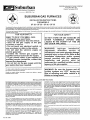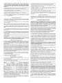
1
ms
uburban
S U B U R B A N M A N U F A C T U R I N G COMPANY
P o s t O f f i c e B o x 399
Dayton, T e n n e s s e e 37321
Manufacturing Company
SUBURBAN GAS FURNACES
CERTIFIED
INSTALLATION INSTRUCTIONS
FOR MODELS
SF-20 SF-25 SF-30 SF-35
The design of the furnace has been listed for installation i n recreational vehicles only. In order for the furnace to operate in conformity with generally accepted
safety regulations, the installation instructions must be followed. Failure t o comply with the installation instructions will void the warrantyon the furnaceand
any responsibility on the part of Suburban Manufacturing Company.
The furnace was inspected before i t left the factory. If any parts are found to be damaged, do not install the furnace. Immediately contact the transportation
company and file a claim.
FOR YOUR SAFETY
FOR YOUR SAFETY
WHAT TO DO IF YOU SMELL GAS:
Extinguish any open flame.
Evacuate all persons from the vehicle.
Shut off the gas supply at the gas
container or source.
Do not touch any electrical switch, or
use any phone or radio in the vehicle.
Do not start the vehicle's engine or
electric generator.
Contact the nearest gas supplier or
qualified service technician for repairs.
If you cannot reach a gas supplier or
qualified service technician, contact the
nearest fire department.
Do not turn on the gas supply until the
gas leak(s) has been repaired.
DO NOT STORE OR USE GASOLINE OR
OTHER FLAMMABLE VAPORS AND
LIQUIDS IN THE VICINITY OF THIS OR
ANY OTHER APPLIANCE.
WARNING! Improper installation,
adjustment, alteration, service or
maintenance can cause property damage,
personal injury or loss of life. Refer to the
installation instructions andlor owners
manual provided with this appliance.
Installation and service must be
performed by a qualified installer, service
agency or the gas supplier.
This book contains instructions covering the operation and maintenance of
your furnace. Keep with unit at all times.
Should you require further information, contact your dealer or nearest
Suburban Service Center.
INSTALLATION INSTRUCTIONS
WARNING! Installation ofthis appliance must bemadein accordance with
the written instructions provided i n this manual. No agent, representative
or employee of Suburban or other person has the authority t o change,
modify or waive any provision of the instructions contained i n this
manual.
CAUTION: This furnace was shipped from the factory set up for the gas
connection to be made at the right rear of the unit as illustrated i n Figure I.
If you wish t o make gas connection through the top of cabinet, you must
remove furnace from cabinet and turn gas inlet fitting 90" CLOCKWISE. DO
NOT TURN FITTING COUNTER-CLOCKWISE, this will loosen fitting and
result i n a gas leak.
These furnaces are designed and installed in such a manner as to be removable
only from the exterior of the recreational vehicle.
CAUTION: If possible, do not install the furnace t o where the vent can be
covered or obstructed when any door on the trailer is opened. If this i s not
possible, then the travel of the door must be restricted i n order t o provide
a 6" minimum clearance between the furnace vent and any door whenever
the door is opened.
NOTE: The exhaust
of this furnace could discolor or warp some
materials. you should verify that the material used on the coach door, panel, or
cover will not discolor or warp from the
temperaturewhenever any door,
panel, or cover is in the open position.
.
CAUTION: Due t o the differences i n vinyl siding, this appliance should not
be installed on vinyl siding without first consulting with the manufacturer of
the siding or cutting the siding away from the area around the appliance
vent.
CAUTION: In any installation in which the vent of this appliance can be
covered due t o the construction of the RV or some special feature of the RV
such as slide out, pop-up etc. always insure that the appliance cannot be
operated by setting the thermostat to the positive
position and
shutting off all electrical and gas supply to the appliance. Never operate
furnace with vent covered.
Form No. 2549-C
NOTE. These furnaces must be installed and vented as described in this manual
that Ihe negative pressure created by the air circulating (return air) fan cannot
affect the combustion air intake or venting of any other appliance. IIis imperative
that the products of combustion be properly vented to the atmosphere and that all
combustion air supplled to burner be drawn from the outside atmosphere. (See
Installing Vent Assembly.)
SO
NOTE: Do not Install the furnace with the vent facing toward the forward end of
the coach.
IMPORTANT: If this furnace is to be connected to a common duct system also
sewing a cooling unit, a manual or automatic damper is required to prevent any
cold conditioned air from circulating back into the furnace. Cold air passing over
the furnace combustion chamber during theoperation ofthecooling unit can result
in the formation of condensation inside the furnace combustion chamber. This
condensation may promote corrosion and premature failure of the combustion
chamber.
SUBURBAN MANUFACTURING COMPANY
Post Office Box 399
Dayton, Tennessee 37321
SUBURBAN GAS FURNACES
CERTIFIED
INSTALLATION INSTRUCTIONS
FOR MODELS
SF-20 SF-25 SF-30 SF-35
The design of the furnace has been listed for installation i n recreational vehicles only. In order for the furnace to operate i n conformity with generally accepted
safety regulations, the installation instructions must be followed. Failure to comply with the installation instructions will void the warranty on the furnaceand
any responsibility on the part of Suburban Manufacturing Company.
The furnace was inspected before i t left the factory. If any parts are found to be damaged, do not install the furnace. Immediately contact the transportation
comnanv and file a claim.
FOR YOUR SAFETY
FOR YOUR SAFETY
WHAT TO DO IF YOU SMELL GAS:
Extinguish any open flame.
Evacuate all persons from the vehicle.
Shut off the gas supply at the gas
container or source.
Do not touch any electrical switch, or
use any phone or radio in the vehicle.
Do not start the vehicle's engine or
electric generator.
Contact the nearest gas si~pplier or
qualified service technician for repairs.
If you cannot reach a gas supplier or
qualified service technician, contact the
nearest fire department.
Do not turn on the gas supply until the
gas leak(s) has been repaired.
DO NOT STORE OR USE GASOLINE OR
OTHER FLAMMABLE VAPORS AND
LIQUIDS IN THE VICINITY OF THIS OR
ANY OTHER APPLIANCE.
WARNING! Improper installation,
adjustment, alteration, service or
maintenance can cause property damage,
personal injury or loss of life. Refer to the
installation instructions andlor owners
manual provided with this appliance.
Installation and service must be
performed by a qualified installer, service
agency or the gas supplier.
This book contains instructions covering the operation and maintenance of
your furnace. Keep with unit at all times.
Should you require further information, contact your dealer or nearest
Suburban Service Center.
1
WARNING! Be sure the furnace and all
ignition systems are "OFF" during any
type of refueling and while vehicle is in
motion or being towed.
INSTALLATION INSTRUCTIONS
WARNING! Installation ofthis appliance must bemade in accordancewith
the written instructions provided i n this manual. No agent, representative
or employee o f Suburban or other person has the authority t o change,
modify or waive any provision of the instructions contained i n this
manual.
These furnaces are designed and installed in such a manner as to be removable
on!y from the exterior of the recreat~onalvehicle.
CAUTION: If possible, do not install the furnace to where the vent can be
covered or obstructed when any door on the trailer is opened. If this is not
possible, then the travel of the door must be restricted i n order to provide
a 6" minimum clearance between the furnace vent and any door whenever
the door i s opened.
NOTE: The exhaust temperature of this furnace could discolor or warp some
materials. You should verify that the mater~alused on the coach door, panel, or
cover will not discolor or warp from the exhaust temperature whenever any door,
panel, or cover is in the open position.
.
CAUTION: Due t o the differences i n vinyl siding, this appliance should not
be installed on vinyl siding without first consulting with the manufacturer of
the siding or cutting the siding away from the area around the appliance
vent.
CAUTION: In any installation i n which the vent of this appliance can be
covered due to the construction of the RV or some special feature of the RV
such as slide out, pop-up etc. always insure that the appliance cannot be
operated by setting the thermostat to the positive "OFF" position and
shutting off all electrical and gas supply t o the appliance. Never operate
furnace with vent covered.
Form No. 2549-C
CAUTION: This furnace was shipped from the factory set up for the gas
connection to be made at the right rear of the unit as illustrated in Figure I.
If you wish to make gas connection through the top of cabinet, you must
remove furnace from cabinet and turn gas inlet fitting 90' CLOCKWISE. DO
NOT TURN FITTING COUNTER-CLOCKWISE, this will loosen fitting and
result in a gas leak.
from being inserted on the valve and to prevent any leaks from
developing. Be sure to check all fittings for leaks including the inlet and
outlet on the valve before reinstalling furnace into cabinet Correct all
leaks immediately. NOTE: The furnace must be in operation to properly
NOTE: These furnaces must be installed and vented as described in this manual
so that the negative pressure created by the air circulating (return air) fan cannot
affect the combustion air intake or venting of any other appliance It is imperative
that the products of combust~onbe properly vented to the atmosphere and that all
combustion alr supplied to burner be drawn from the outside atmosphere. (See
Installing Vent Assembly.)
NOTE: Do not install the furnace with the vent facing toward the fofward end of
the coach.
IMPORTANT: If this furnace is to be connected to a common duct system also
serving a cooling unit, a manual or automatic damper is required to prevent any
cold conditioned air from circulating back into the furnace. Cold air passing over
the furnace combustion chamber during theoperation of the cooling unit can result
in the formation of condensation inside the furnace combustion chamber. This
condensation may promote corrosion and premature failure of the combustion
chamber.
NOTE: These furnaces shall be installed so the electrical components are
protected from water.
These furnaces are design certified for propane1LP gas only. Do not attempt to
convert to natural gas.
Gas supply pressure for purposes of input adjustment:
Max~mum- 1 3 W.C '
Minimum - 11" W.C.'
(W.C - Water Column).
In the U.S.A.. the installation of the furnace must be in accordance w~thlocal
codes and regulations. In the absence of local codes and regulations. refer to the
latest edition of:
I.Standard for Recreational Vehicles ANSl A-1 19.2lNFPA 501C.
2. National Fuel Gas Code ANSl 2223.1
3. Furnace must be electrically grounded in accordance w ~ t hthe latest edition of
the National Electrical Code ANSllNFPA No. 70.
In Canada, the furnace must be installed in accordance with:
I.Standard CANICSA-2240 Recreational Vehicles.
2. CSA Standard CANICSA-2240.6.2-M86 Electrical
Recreational Vehicles.
Requirements
for
3. When an appliance is installed d~rectlyon carpet~ng,tile or other combustible
material. other than wood flooring. the appliance shall be Installed on a metal or
wood panel extending the full width and depth of the appliance If preferred, the
carpeting, tile or combustible materials, other than wood may be cut away the full
length and depth of the appliance plus the appliance minimum clearances to
combustible. (See Table 2.)
4. Locate center lines for exhaust and intake tubes as shown in Figure 1.
5. Cut two 2-314" diameter holes through the removable wall section. (See Figure
2.)
6 . Put furnace in place, making sure that rear of furnace cabinet 1s as close to
inner wall section of the coach as posslble and still assure proper vent tube
overlap. (See Installing Vent Assembly.)
7. Using the two #10 x 314 sta~nlessscrews provided, fasten furnace cabinet to
floor of coach through the holes provided in the furnace cabinet (See Figure 4.)
8. Be sure furnace is secured within furnace cabinet (See F~gure4.)
9. Install vent assembly. (See instructions for installing vent )
C. INSTALLATION USING THE FURNACE ACCESS DOOR SUPPLIED BY
SUBURBAN (See Fiqure 4)
) Maximum wall thickness for this type installation i s 2".
3. Standard CANICSA-2240.4.2-M86 Installation Requirements for Propane
Appliances and Equipment in Recreational Vehicles.
1. Locate the furnace near lengthwise center of coach.
4. CANICGA-El49 Installation Codes.
2. Choose a location for installation out of the way of wires, plpes, etc., which
might interfere with the installation. Adhere to the minimum clearances from the
cabinet to combustible construction as listed in Table 2. Refer to Figure 3 for
illustration of furnace clearances.
5. Any applicable local codes and regulations.
This unit is equipped with an electric igniter device that has an energy
consumptionof .1 amp @ 12 volts D.C.
WARNING! Extension tubes cannot be used. If you try to extend the vent,
it will result i n improper installation which could cause unsafe furnace
operation.
Thereare three (3) methods described below for installing the furnace. Regardless
of the method you choose, we require an opening be provided in the exterior of
the trailer or motor home for free, unobstructed removal of the furnace. This
exterior, removable panel or wall section of the trailer or motor home must be a
minimum of 17-314 x 8.
3. When an appliance is installed directly on carpeting, tile or other combustible
material, other than wood flooring, the appliance shall be installed on a metal or
wood panel extending the full width and depth of the appliance. If preferred, the
carpeting, tile or combustible maters, other than wood may be cut away the full
length and depth of the appliance plus the appliance minimum clearances to
combustibles. (See Table 2 )
4. After furnace location has been determined, cut an opening 18-7/32 x 8-9/32"
through the inner coach wall and the outer wall (skin) of the coach.
5. Caulk around opening as illustrated. Apply generously. The purpose of the
caulking is to seal the back side of the door frame and the coach skin water tight.
It is important that adequate return air be provided to assure normal heating and
operation of the furnace. Failure to provide the minimum return air will cause
erratic furnace cycling. Refer to the chart shown below for minimum return air
requirements.
6. Secure frame to outer wall (skin) through the holes in the frame. Screws should
be used. (See Figure 4.) NOTE: Do not place screws into the holes required for
mounting the door.
Return Air Requirements
7. Slide furnace in place. The back of the furnace should be installed against or
as close as possible to the flange on the door frame. (See illustration.) The
furnace must maintain 112" overlap on the intake and 1.114" overlap on the
exhaust.
Model
Minimum Free (unobstructed) Area
SF-20/25/30/35
55 Sq. In.
TABLE I
8. Using the two # I 0 x 314 stainless screws provided, fasten furnace cabinet to
floor of coach through the holes provided in the furnace cabinet. (See Figure 4.)
9. Be sure furnace is secured within furnace cabinet. (See Figure 4.)
NOTE: Return air must be from within the living area of the coach.
A. INSTALLATION DIRECTLY AGAINST OUTER PANEL OF COACH
(See Figure I ) (Panel supplied by installer)
Maximum wall thickness for this type installation i s 2".
1. Locate the furnace near lengthwise center of the coach.
2. Choose a location for installation out of the way of wires, pipes, etc.. which
might interfere with the installation. Adhere to the minimum clearances from the
cabinet to combustible construction as listed in Table 2. Refer to Figure 3 for
illustration of furnace clearances.
10. Position furnace access door over the frame. Secure the door to the coach
skin. Be sure the coach skin is of sufficient strength to keep furnace access door
in place and insure a tight seal. It may be necessary to build a wood or metal
frame around the opening in order to provide adequate strength for securing door.
CAUTION: The screws provided with the door may not be o f sufticient length
and size for all applications and i t may be necessary for the installer to
substitute screws i n order to adequately secure the furnace access door.
11. Install vent assembly. (See instructions for installing vent.)
Model
3. When an appliance is installed directly on carpetlnq, tile or other combustible
material, other than wood flooring, the applianceshalrbe installed on a metal or
wood panel extending the full width and depth of the appliance. If preferred, the
carpeting, tile or combustible materials, other than wood may be cut away the full
length and depth of the appliance plus the appliance minimum clearances to
combustibles. (See Table 2.)
Front
Left
Side
Right
Side
Top
Bottom
Back
Exhaust and
Intake Tube
4. Cut an opening through the inner wall. This will allow the rear of the furnace to
be installed against the outer panel of the coach.
5. Locate center lines for exhaust and intake, as shown in Figure 1
-NOTE-
6. Cut two 2-114" diameter holes through the outer panel of the coach. (See
Figure 1.)
7. Put furnace in place. making sure that rear of the furnace cabinet is as close
to outer panel of the coach as possible and still assure proper vent tube overlap.
(See Installing Vent Assembly.)
8. Using the two # l o x 314 stainless screws provided, fasten furnace cabinet to
floor of coach through the holes provided in the furnace cabinet. (See Figure 4.)
9. Be sure furnace is secured within furnace cabinet. (See Figure 4.)
10. Install vent assembly. (See instructions for installing vent.)
B. INSTALLATION FLUSH WITH INNER WALL OF COACH
(See Figure 2) (Exterior panel supplied by installer)
Maximum wall thickness for this type installation is 2".
I.Locate the furnace near lengthwise center of the coach.
2. Choose a location for installation out of the way of wires, pipes, etc, which
might interfere with the installation. Adhere to the minimum clearances from
cabinet to combustible construction as listed in Table 2. Refer to Figure 3 for
illustration of furnace clearances.
0" MEANS TO SPACER BUMPS
I
CLEARANCE FROM DUCTS TO
COMBUSTIBLE MATERIAL 114" (See Fiaure
3\r
*
TABLE 2
-
I
INSTALLING VENT ASSEMBLY
The vent outlet must be installed so it is in the same atmospheric pressure zone
as the combustion air intake. The exhaust and intake tubes must be installed from
the outside, pass through the RV skin and slide onto the furnace exhaust and
intake.
WARNING! Do notalter the vent assembly supplied with this furnace. Any
modifications will result inimproper installation whichcould causeunsafe
furnace operation.
CAUTION! Combustion air must not be drawn from the living area. All air for
combustion must be drawn from the outside atmosphere. All exhaust gases
must be vented to the outside atmosphere - never inside the RV. Therefore,
i t is essential to insure that the vent cap and tube assemblies are properly
installed.
1. Apply caulking to RV skin behind vent capas shown in ~ig'ure1 Apply caulking
generously around perimeter of vent cap and across center as shown
2. Insert Intake tube through RV ski11and slide it onto the furnace intake (See
Figure 2 ) Minimum tube overlap of 112" is requlred
3. Insert vent cap exhaust tube through RV skin and slide it onto the furnace
exhaust (See Figure 2 ) Minimum tube overlap of 1 114" is required
4. Attach vent cap assembly to outer sldn of RV wilh the six (6) screws provided
Do not install vent assembly upside down The words "Suburban" and "Dayton.
Tenn." must be right side up.
CONNECTING GAS SUPPLY
Connect the gas supply to the furnace at the manifold, following the suggestions
outlined below. It will be necessary10 hold the flare fitting on the furnace manifold
when connecting or loosening gas line
NOTE The compound used on threaded joints must be resistant to liquefied
petroleum (LP) gas.
NOTE. The appliance must be disconnected from the gas supply piping system
during any pressure testing of that system at test pressure in excess of 112 PSIG.
The appliance must be isolated from the gas supply piping during any pressure
testing of the gas supply piping system at test pressure equal to or less than 112
PSIG.
1. A 318" male flare connection is provided for gas line hookup. Some standards
may require the use of a manual shut off valve in the gas line external to the
furnace cabinet.
2. In order to maintain a check ofgas supplied pressure to the furnace, Suburban
advises the installer to provide the 118 NPT plug tap for test gauge connection
immediately upstream of the gas supply connection to the furnace and that it be
readily accessible.
3. After the furnace has been connected to the gas supply, all jo~ntsmust be
checked for leaks.
WARNING! Never check for leaks with an open flame. Turn on the gas and
apply soapy water to all joints to see if bubbles are formed.
CONNECTING ELECTRICAL SUPPLY
,
CAUTION: This furnace i s designed for negative ground 12 volt D.C. system
only. Do not attempt to alter the furnace for a positive ground system o r
connect the furnace directly to 115 volts A.C. Damage to furnace component
parts will occur.
Be sure all wiring to the furnace is of heavy enough gauge to keep the voltage
drop through it to a minimum and to provide enough power for start-up surge. No
1'2 gauge wire is recommended. If any of the original wire that is supplied with the
appliance must be replaced, it must be replaced with type 105" C or its equivalent.
Power supply connections are to be on the right side of the furnace. The wires are
color coded, red for positive (+) and yellow for negative (-). This polarity must be
observed so the furnace motor will run the proper direction of rotation to insure
correct air delivery. (See wiring diagram.)
If the furnace power supply is to be from a converter, we recommend that the
converter system used to power the furnace be wired in parallel with the battery.
This will serve two purposes:
1. Provide a constant voltage supply to the furnace.
2. Filter any A.C. spikes or volt surges.
CONNECTING DUCTS TO FURNACE
The following duct requirements must be followed in order to assure proper
operation of the furnace:
A. The minimum open duct areas listed below must be maintained throughout
entire duct system including through register:
C. Avoid making any sharp turns in the duct system Sharp turns will increase the
static pressure in the plenum area and could cause the furnace to cycle.
D. Avoid making a lot of turns in the duct system. The straighter the duct system,
the better the performance of the furnace.
E. Maintain a minimum of 114" clearance where ducts pass through any
combustible construction, such as coach cabinetry. (See Figure 3 ) NOTE: UL
llsted duct materials can be 0 clearance.
F. Do not install air boosters in the duct system Such devices wlll cause the
furnace lo cycle on limit and to have erratic sail switch operation
NOTE After installation of the furnace and duct system is completed, adjustments
must be made to obtain a temperature rise within the range specified on the
Rating Plate
INSTALLING THERMOSTAT
Locate the room thermostat approximately 4-112 feet above the floor on an inside
bulkhead where it is not affected by heat from any source except room air.
Connect thermostat wiring to the blue wires on right s ~ d eof furnace. (See wiring
diagram )
PREVENTIVE MAINTENANCE
WARNING! If the user of this appliance fails to maintain it i n the condition
i n which it was shipped from the factory or if the appliance is not used
solely for its intended purpose or if appliance is not maintained in
accordance with the instructions in this manual, then the risk of a fire
andlor the production of carbon monoxide exists which can cause
CAUTION: Label all wires before disconnecting forservicing. Proper polarity
must be observed so the furnace motor will run with the proper direction of
rotation to insure correct air delivery. (See wiring diagram).
CAUTION: Label all wires prior to disconnection when servicing controls.
Wiring error can cause improper and dangerous furnace operation.
Always verify proper operation of furnace after servicing.
Your furnace should be inspected by a qualified service agency yearly before
turning the furnace on. Particular attention should be given to the following Items.
1. lnspect furnace installation and vent termination to be sure furnace is properly
secured in place (see Installation Instructions), that vent terminates to the
atmosphere, and that vent tubes overlap properly (see Installing Vent Assembly.)
2. lnspect chamber and venting to assure that these components are physically
sound wlthout holes or excessive corrosion and that the installation and/or reinstallation is In accordance with Suburban's installation instructions. (Reference
installation manual supplied with furnace.)
WARNING! It is imperative that the products of combustion be properly
vented to atmosphere and that all combustion air supplied to burner be
drawn from outside atmosphere.
3. Check the base on which furnace is mounted. Be sure it is physically sound.
void of any sagging, deterioration, etc.
4. lnspect furnace, the venting, ducting and gas piping lo furnace for obvious
slgns of deterioration. Correct any defects at once.
5. lnspect combustion chamber for restrictions in exhaust or intake. It is
imperal~vethat the flow of intake combustion air and the flow of exhaust gases
being expelled to the outside atmosphere not be obstructed. Any soot or loose
debr~sshould be blown out using compressed air. (See Figure 7.)
6 . lnspect all gaskets. If any gaskets show signs of leakage or deterioration.
replace them. Safe operation of Ihe furnace depends on all gaskets being tight.
7. lnspect return air inlet openings to the furnace. Remove any restrictions to
assure adequate air flow.
You, as the ownerluser, should inspect the furnace monthly during the
heating season for presence of soot on vent. Operating the furnace under this
condition could lead to serious property damage, personal injury or loss of life. If
soot is observed on the vent, immediately shut the furnace down and contact a
qualified service agency.
Listed below are several safety related items that you should follow during the
heating season to assure continued safe operation of the furnace.
1. lnspect furnace venting. Venting must be free of obstructions, void of soot, and
properly terminated to the atmosphere. (See Installing Vent Assembly.)
WARNING! Do not install screens over the vent for any reason. Screens
will become restricted and cause unsafe furnace operation. Accessories
are being marketed for RV products which we do not recommend. For
your safety, only factory authorized parts are to be used on your furnace.
NOTE: Ducts terminating i n a dead air space (like holding tank
compartments) with n o means for return air recirculation should not be
counted in the required duct area. Also ducts 2" in diameter o r smaller
should not be counted i n the required duct area.
.
6.Make the duct connections at the furnace cabinet tight. Loose connect~onswill
result in overheating of the component parts on the furnace and a reduction of the
heated air flow through the duct system.
2. Periodically inspect the vent for obstructions or presence of soot. Soot is
formed whenever combustion is incomplete. This is your visual warning that the
furnace is operating in an unsafe manner. If soot is present, immediately shut
furnace down and contact your dealer or a qualified service person.
3. Keep furnace clean. More frequent cleaning may be required due to excessive
lint from carpeting, bedding material, etc. It is imperative that control
compartments, burners and circulating air passageways of the appliance be kept
clean.
4. The motor is permanently lubricated and requires no oiling
5. Keep the furnace area clear of any combust~blematerials, gasollne or other
flammable vapor and I~qu~ds.
8. Remove gas llne
6 Before operating furnace check the locat~on
of the furnace vent to make sure
~twill not be blocked by the openlng of any door on the trader If ~tcan be blocked
do not operate the furnace w ~ t hthe door open
TO REINSTALL
7 Do not restrlct the flow of combust~onalr or the warm alr clrculat~onto the
furnace To do so could cause personal Injury andlor death
2. Connect gas Ilne.
8 Never operate the furnace ~fyou smell gas Do not assume that the smell of
gas ~n your RV 1s normal Any tlme you detect the odor of gas ~t 1s to be
cons~deredllfe threatening and corrected lmmedlately Ext~ngulshany open
flames ~nclud~ng
cigarettes and evacuate all persons from the veh~cleShut off gas
supply at LP gas bottle (See safety notlce on front cover of th~smanual )
9 lmmed~atelyshut furnace down and call a servlce agency ~ffurnace cycles
erratically or delays on lqnltlon
WARNING! Should overheating occur, or the gas supply fail to shut off,
shut off the manual gas valve to the appliance before shutting off the
electrical supply.
10. Never attempt to repalr damaged parts. Always have them replaced by a
qualified service agency
11. Never attempt to repalr the furnace yourself Seek the help of a qualified
service person.
12. Never restrict the ducting installed by your tra~lermanufacturer. Todoso could
cause improper furnace operation
13. Do not install air boosters in the duct system. Such devices will cause the
furnace to cycle and to have errat~csail switch operat~on.
9. Remove t~e-downscrew at blower base and remove furnace from cabinet
I . Slide u n ~lnto
t cabinet and secure w ~ t hscrew at base of blower.
3. Check gas connections for leaks using a soap and water solution. Correct any
gas leaks immed~ately
4. Reinstall module board and panel assembly
5. Reconnect electrode wire to board
6. Reconnect power supply to board.
7. Reconnect power to furnace. NOTE If thls connection was made inside the
cabinet, care must be exercised to prevent wires from coming In contact with the
room alr blower wheel
8. Reinstall optional back.
9. Reinstall vent cap.
10. Provlde power to furnace.
OPERATING INSTRUCTIONS
WARNING! Do not operate furnace while vehicle is in motion or being
towed.
NOTE: During initial firing of this furnace, a burn-off of excess paint and oils
remaining from manufacturing process may cause 'smoking" for 5 - 10 minutes.
1. Stop! Read Users Information Manual supplied w~thfurnace.
14. Clothing or other flammable materlal should not be placed on or near the
appliance
2. Turn the manual valve (if so equipped) or the valve at the outside LP tank to
the "OFF" position. Do not force.
15. Always follow the operat~nginstructions. Do not deviate from the step-by-step
procedures.
3. Set thermostat above room temperature to begin blower operation A slight
delay will occur before the blower comes on. Allow blower to run for 5 minutes for
combustion chamber purge cycle.
16. Do not use this appl~anceif any part has been submerged under water.
Immediately call a quallfled service technician to inspect the appliance and to
replace any part of the control system and any gas control that has been
submerged under water.
17. When considering add-on rooms, porch or patio, attention must be given to the
ventlng of your furnace For your safety, do not terminate furnace vent inside addon rooms, screen porch or onto patios. Doing so will result in products of
combustion being vented into the room or occupied areas.
18. In any installation ~nwhlch the vent of this appliance can be covered due to the
construction of the RV or some spec~alfeature of the RV such as slide out, popup, etc. always insure that the appliance cannot be operated by setting the
thermostat to the positlve 'OFF" position and shutting off all electrical and gas
supply to the appliance. Never operate furnace with vent covered.
INSTALLATION AND REMOVAL OF UNlT
INSTALLED FROM INSIDE
TO REMOVE
1. Disconnect power supply at furnace
2. Remove vent cap assembly
4. After 5 minutes, move thermostat lever below room temperature. Blower will
remain on. Wait approximately 2 minutes for blower to go off.
5. Open manual shut-off valve (ifso equipped) or the valve at the outside LP tank.
Correct operating characteristics depend on the valve being positioned fully open.
Never attempt to operate with a valve partially closed. NOTE: This furnace is
equipped with a valve shut-off switch with switch in 'OFF" position. Gas will not
flow to burner nor will the furnace operate.
6. Set thermostat lever to desired setting. If set above room temperature, blower
will come on.
7. Allow 30 seconds for main burner to light after blower comes on. This furnace
is equipped with an ignition device which automatically lights the burner. Do not
try to light the burner by hand.
8. If burner does not light, repeat Steps 1 through 8.
9. If after three (3) attempts with no ignition, go to shut down and contact your
dealer or a local recreational vehicle service agency. Do not continue to cycle
furnace through thermostat in an attempt to get ignition. NOTE: If furnace should
lock out, the blower will go off in 5 minutes and remain off until unit is reset by
reactivating thermostat.
TO SHUT DOWN
3. Disconnect gas connections
4. Remove cabinet front (2 screws).
5. Remove tie-down screw from center of unit and remove furnace from cabinet.
TO INSTALL
1. Slide unit into cabinet. NOTE: Care must be taken in routing wiring to back of
cabinet and outside of cabinet.
2. Reinstall tie-down screw
3. Reinstall cabinet front
4. Connect gas line.
5. Check gas connectlons for leaks using a soap and water solution. Correct any
gas leaks immed~ately.
6. Reinstall vent cap assembly
7. Reconnect power supply.
INSTALLATION AND REMOVAL OF UNlT
WHEN OPTIONAL BACK IS USED
TO REMOVE
I . Break power to furnace
2. Remove vent cap assembly
3. Remove optional back
4. Disconnect power supply at furnace.
1. Set the thermostat to lowest setting, then move lever to "OFF" position.
2. Turn manual shut off valve (if so equipped) to the'OFFn position. Do not force.
ELECTRODE ADJUSTMENT
For consistent ignition of the burner, it is important thatthe electrode be positioned
properly over the top of the burner. The electrode was set at the factory for proper
ignition and should not need further adjustment; however, if you should
experience inconsistent ign~tion,reposition electrode as follows:
Equipment needed:
flashlight, black felt-tip pen, needle-nose pliers and measuring tape
NOTE: Furnace must be removed. (See instructions for removing unit.)
1. Remove burner from combustion chamber by removing six (6) screws which
attach the burner to the chamber and air baffles (plates).
2. Locate the lance in relation to the burner ports for electrode positioning by:
a. Shine a flashlight into the burner venturi as illustrated (Be sure flashlight
lens is against the end of the burner.)
b. Light will reflect off the lance in the venturi of the burner and shine through
a portion of the two (2) rolls of burner ports in the top of the burner.
c. Using a black felt-tip pen, mark a line along top of burner 3 / 1 6 in back of
the lance and parallel with lance. Make an additional mark indicating the
center line of the lance. (See illustration.) Both marks will be used later as
reference marks; therefore, keep llnes thin.
3. Reassemble the burner.
6. Disconnect electrode wire from module board.
4. Adjust electrode so the electrode probe is positioned along the marked center
llne of the burner lance and the tip of the electrode terminates 3 / 1 6 from the back
of the lance. (At the line marked in Step 2-c ) (See Figure 5.)
7. Remove the two (2) screws securing module board and panel assembly to
firewall and pull out assembly. EXERCISE CARE NOT TO DAMAGE BOARD.
5. IMPORTANT: Besureelectrode probemaintains a 118" spark gap over the
burner as illustrated.
NOTE T h ~ swill allow more room for making the gas connectlons at the flare
fitting It will be necessary to hold the flare fitting with a wrench when tightening
or loosen~ngthe gas Ilne.
6. Reinstall the furnace into the cablnet following the instructions in the manual.
5. Disconnect power supply plug from module board.
APPLY CAULKING B E W E E N RV SKlN AND BACK OF PAIN SHIELD
S l D E s K l N (PANEL]
TUBE. INTAKE AIR
CAULK BEHlND VENTCAP AS SHOWN TO SEAL
BETWEEN EXHAUST A N 0 INTAKE AND TO
PREVENT MOISTURE INSIDE FURNACE
COMPARTMENT APPLY CAULKING GENEROUSLY
AROUND PERlMETER OF VENT CAP AND ACROSS
CENTER AS SHOWN CENTER P U T Y STRIP IS
ESSENTIAL
D E T A I L "A"
SIDE SKlN (PANEL)
W I M U M W U L THICKNESS
FURNACE CABIN
Figure 1
DIA - 2 HOLES
(SEE FIGURE # I FOR
CENTERLINE DIMENSIONS:
2 3/4'
AIR INTAKE TUBE
V l T H GASKET
3'
TO SPACER
SEE DETAIL 'A'
0' TO SPACER
MAINTAIN A l / 4 * INCH CLEARAIICE
WHERE DUCTS PASS THROUGH
A CABINET VALL. UL LISTED DUCT
MATERIALS CAN BE 0' CLEARANCE.
fl
HAXIHUH WALL THICKNESS FOR THIS
TYPE INSTALLATION I S 2'
Figure 3
Figure 2
FURNACE
i r
TIE-DOWN SCREW
(FURNACE TO TABINET)
r OUTSIDE SKIN
CAULK ALONG THE EDGE OF THE CUTOUT
( A L L THE WAY AROUND)
2 ) PLACES AS ILLUSTRATED
OF CABINET MUST BUTT
ST THIS EDGE OF THE FRAHE
CAULK BEHIND V E N T CAP AS SHOWN TO
SEAL BETWEEN EXHAUST AND I N T A K E AND
TO PREVENT MOISTURE I N S I D E FURNACE
COHPARTHENT. APPLY CAULKING GENEROUSLY
AIR I N T A K E TUBE
V l T H GASKET
SECURE FRAHE TO
OUTER PANEL W I T H SCREWS
(L6 PLACES)
OOR HOUNTING
NT CAP b EXHAUST TUBE
I
I
Figure 4