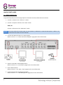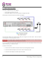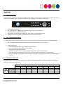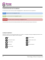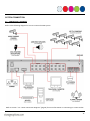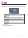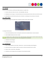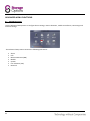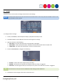
1
CAUTION RISK OF ELECTRIC SHOCK DO NOT OPEN TO REDUCE THE RISK OF ELECTRIC SHOCK, DO NOT REMOVE THE COVER. NO USER SERVICABLE PARTS INSIDE. REFER SERVICING TO QUALIFIED PERSONNEL. The lightning flash with arrowhead symbol, within an equilateral triangle, is intended to alert the user to the presence of noninsulated “dangerous voltage” within the product’s enclosure that may be of sufficient magnitude to constitute a risk of electric shock. The exclamation point within an equilateral triangle is intended to alert the user to the presence of important operating and maintenance (servicing) instructions in the literature accompanying the appliance. 2 WARNING: TO PREVENT FIRE OR SHOCK HAZARD, DO NOT EXPOSE THIS UNIT TO RAIN OR MOISTURE CAUTION: TO PREVENT ELECTRIC SHOCK, ENSURE THE PLUG IS FULLY INSERTED INTO A MAINS SOCKET IMPORTANT SAFEGUARD All lead-free products offered by the company comply with the requirements of the European law of the Restriction of Hazardous Substances (RoHS) directive, which means our manufacturing processes and products are strictly “lead-free” and without the hazardous substances cited in the directive. The crossed-out wheeled bin mark symbolizes that within the European Union the product must be collected separately at the product’s end-of-life. This applies to your product and any peripherals marked with this symbol. Do not dispose of these products as unsorted municipal waste. Contact your local dealer for procedures for recycling this equipment. DISCLAIMER We reserve the right to revise or remove any content in this manual at any time. We do not warrant or assume any legal liability or responsibility for the accuracy, completeness, or usefulness of this manual. The content of this manual is subject to change without notice. RECOMMENDATIONS AVOID DUSTY LOCATIONS: INSTALL IN VENTILATED SPACE: DO NOT EXPOSE TO MOISTURE: DO NOT DROP: DO NOT OPEN CHASSIS: Excessive build-up of dust may cause the unit to fail. Ensure adequate airflow around the DVR to prevent overheating. Exposing the unit to water poses high risk of electric shock. Doing so could damage internal components. No user-serviceable parts inside. TRADEMARK ACKNOWLEDGEMENTS Internet Explorer, Microsoft & Windows are registered trademarks of Microsoft Corporation. Apple, iPhone, iPad and iTunes are registered trademarks of Apple Computer, Inc. DEFAULT PASS CODE INFORMATION By default, pass codes are disabled on the system. You do not need to enter a pass code when accessing any menus. For security purposes, it is highly recommended to enable pass codes via the Password Menu. WARRANTY AND TECHNICAL SUPPORT In the event that you need further assistance with this product you can call us, at local UK rate on the number below and our UK-based experts will be happy to help you (they’re available Mon-Fri 9am – 5.30pm, excluding bank holidays). Alternatively visit our website at www.storageoptions.com/support or send us an email at the address below. This product is backed by a 12 month warranty to cover the unlikely event of something going wrong. Should you suspect a fault with your product please contact our support team in the first instance. UK: 0844 248 7191 Ireland: 00353 (0) 94 937 4026 E-Mail: [email protected] 3 TABLE OF CONTENTS QUICK START GUIDE 1.1 – Basic Connectivity 1.2 – Wall Mounting A Camera 1.3 – Power Connection Diagram OVERVIEW 6 6 7 8 9 2.1 – System Overview 2.2 – Environment Adaptability 2.3 – Recording Capacities 9 9 9 CONVENTIONS USED IN THIS MANUAL 10 PACKAGE CONTENTS 10 SYSTEM CONNECTION 11 5.1 – Connectivity Diagram BASIC OPERATION 6.1 – Front Panel 6.2 – Rear Panel 6.3 – Remote Control 6.4 – Mouse Control 6.5 – Using The Sub Menu 6.6 – Power On / Off 6.7 – Pass Codes 6.8 – Format The Hard Disk Drive 6.9 – System Login 6.10 – Playback 6.11 – On-screen Playback Controls BASIC MENU FUNCTIONS 7.1 – Main Menu 7.2 – Search 7.3 – File List 7.4 – Backup 7.5 – Record Mode 7.6 – Recording Schedule 7.7 – HDD Management 7.8 – Basic Setup 7.9 – Language 7.10 – Date / Time 7.11 – Daylight Saving Time 7.12 – Password 7.13 – User Permissions 7.14 – Display 7.15 – Preview 7.16 – Video / Audio 7.17 – Volume Setup 4 11 12 12 13 14 15 15 16 16 16 16 17 17 18 18 19 20 21 22 24 25 26 26 27 27 28 29 30 31 31 31 TABLE OF CONTENTS (CONTINUED) ADVANCED MENU FUNCTIONS 32 8.1 – Advanced Setup 8.2 – Alarm 8.3 – E-Mail Setup 8.4 – System Info 8.5 – Motion Detection 8.6 – Mobile 8.7 – System 8.8 – Firmware Upgrade 8.9 – Parameter Export 8.10 – Parameter Import 8.11 – Pan Tilt Zoom (PTZ) 8.12 – Network 8.13 – DDNS 8.14 – UPnP 32 33 34 35 35 36 37 38 38 38 39 40 41 42 REMOTE SURVEILLANCE SOFTWARE 43 9.1 – Using Remote Surveillance 9.2 – Main Screen 9.3 – Live View 9.4 – Recording 9.5 – Sub Menu 9.6 – PTZ Control 9.7 – Screen Captures 9.8 – Playback 9.9 – Search 9.10 – Remote Backup 9.11 – Remote Setup 9.12 – Record 9.13 – Alarm Setting 9.14 – PTZ 9.15 – Network 9.16 – Setting 9.17 – Maintenance 9.18 – Host Info 44 45 46 46 46 47 47 48 49 49 50 50 51 51 52 52 53 53 SOFTWARE CD 54 USING MEYE FOR MOBILE VIEWING 55 HARD DISK DRIVE INSTALLATION 56 TROUBLESHOOTING 57 APPENDIX – PRODUCT SPECIFICATION 58 5 QUICK START GUIDE 1.1 – BASIC CONNECTIVITY To get started quickly with the Storage Options 8 Channel CCTV DVR, follow these instructions: 1. Connect a camera to the “Video In 1” socket. 2. Connect a computer monitor to the “VGA” socket. AND / OR Connect a television to the “Video Out” socket. NOTE You must select the correct input on your monitor / television to view the DVR system. Refer to its manual for instructions on how to do this. 3. Connect the DVR and camera to a mains supply. Refer to section “1.3 – Power Connection Diagram” (page 8) for more information. 4. Switch on the DVR via the ON/OFF switch. Refer to section “6.1 – Front Panel” (page 12) for more information. 5. Set the date and time. Refer to section “7.10 – Date / Time” (page 27) for more information. 6. Format (prepare) the Hard Disk Drive (HDD). Refer to section “7.7 – HDD Management” (page 25) for more information. 6 1.2 – WALL MOUNTING A CAMERA Each Storage Options camera is supplied with a mounting kit for attaching it to a wall. Before you affix the camera in position, please ensure the cable is of adequate length to reach the DVR. To mount the camera on a wall or ceiling, follow these instructions: 1. Ensure the surface you want to mount the camera on is solid and can support the weight. 2. Accurately mark on the wall the position of the holes to be drilled. 3. Drill to the correct depth in the wall, as indicated by the plugs. 4. Insert plugs into the drilled holes. 5. Secure the bracket to the wall using the provided screws. To attach the camera to the bracket: 1. Screw it onto the exposed thread. 2. Tighten the bolt to lock it in place. To adjust the camera’s position, turn the bolt arms anti-clockwise to release the corresponding point of adjustment, position the camera, then turn the bolt arms clockwise to re-tighten. 7 1.3 – POWER CONNECTION DIAGRAM This system is supplied with two mains adapters: 1. Mains adapter specifically for the DVR. 2. Multi-power adapter to connect up to 8 cameras to a single mains socket. Connect power to the DVR and cameras as shown in this diagram: BLUE = Camera mains connection GREEN = DVR mains connection RED = Video connection The multi-power adapter has 8 separate cables which join to plug into one mains socket. These are used for connecting power to each Storage Options camera. CAUTION The 1-8 power splitter is designed for use ONLY with Storage Options cameras! DO NOT attempt to connect other brands as this may present a risk of fire! Each Storage Options CCTV camera (sold separately) also comes with its own mains adapter should you wish to plug them all in separately, or in different locations. To connect to mains power: 1. Connect each of the 8 cables to the power sockets on up to 8 Storage Options cameras. 2. Connect the DVR mains adapter to the “DC 12V” socket on the DVR rear panel. 3. Connect the mains adapters to suitable 3-pin mains sockets. 8 OVERVIEW 2.1 – SYSTEM OVERVIEW Storage Options presents a complete CCTV solution for home or office security, featuring up to eight high-quality cameras, internal HDD, easy setup and configuration, alarm triggers, and network connectivity. H.264 video compression Twin USB interface – USB2.0 for data backup, USB1.1 for mouse operation 3.5” SATA HDD (up to 2TB compatible) 16 bit colour translucent user-friendly GUI, with notes for selected menu items Supports live view, parameter setting and backup via network interface 2.2 – ENVIRONMENT ADAPTABILITY For safety while using the DVR and to prolong the device’s useful life, please pay attention to the following details: 1. When installing the device, please comply with all the electric product safety criteria. 2. Power and ground: Do not touch the DVR or mains adapter with a wet hand. Do not drop liquid on the DVR or mains adapter. Do not put any object on the DVR. Please use a soft, dry cloth to clean the DVR; do not use chemical cleaning fluids. The DVR will have voltage before start-up if the mains adapter is connected to a mains socket. Please unplug the mains adapter from its socket if the DVR is not going to be used for a prolonged period of time. 2.3 – RECORDING CAPACITIES This table shows the amount of recording time (in days*) of the DVR, depending on which size HDD is installed and how many cameras are connected: Number of Cameras HDD Capacity 1 2 3 4 5 6 7 8 500GB 100 50 33 25 20 17 14 13 1TB 200 100 66 50 40 33 29 25 2TB 400 200 132 100 80 67 57 50 * All values are approximate. Actual results may vary according to recording conditions. 9 CONVENTIONS USED IN THIS MANUAL At various points in this manual you will see highlighted text. Please refer here for an explanation: NOTE TIP Important notes are highlighted in blue. Tips on best practice are highlighted in green. CAUTION Important cautions and warnings are highlighted in red. Unless otherwise stated, all functionality described in this manual is performed using the USB mouse. PACKAGE CONTENTS Check the contents of your DVR package against this checklist. If anything is missing or damaged, please do not use the system, and inform your supplier as soon as possible. DVR DVR power supply Camera power supply 1-8 power splitter cable Remote control Mouse Software CD Instruction Manual Screws and plugs 10 SYSTEM CONNECTION 5.1 – CONNECTIVITY DIAGRAM Refer to the following diagram for how to connect the DVR system. Refer to section “1.3 – Power Connection Diagram” (page 8) for more information on connecting to a mains socket. 11 BASIC OPERATION 6.1 – FRONT PANEL 1. POWER: Press to turn the system on / off (ensure the rear panel ON/OFF switch is in the “on” position). 2. IR SENSOR: IR receiver for the remote control. Do not cover. 3. LED INDICATORS: Shows status of HDD activity, recording, alarm, network and power. LABEL COLOUR DESCRIPTION HDD ORANGE REC RED Indicates whether the DVR is currently recording. ALM RED Lights to indicate an alarm trigger has occurred. FULL RED Lights to indicate the HDD is full. NET GREEN Flashes to indicate HDD activity. Flashes to indicate network traffic. 4. CHANNEL NUMBERS / PLAYBACK: Press buttons 1-8 to view the selected channel in full-screen. During playback, press the following: BUTTON DESCRIPTION 6 Rewind. Press multiple times for 2x / 4x / 8x. 7 Freeze playback to one frame, then press again to advance frame-by-frame. 8 Play video. 9 Slow playback speed by 1/2, 1/4, 1/8. 0 Fast forward. Press multiple times for 2x / 4x / 8x. 5. MENU / EXIT: Press to open / close the main menu. 6. NAVIGATION / OK: Press the navigation buttons (↑, ↓, ←, →) to highlight menu options. Press OK to confirm selections. 7. USB: Connect a USB flash drive to the top port (labelled “USB 2.0”) for data backup and firmware upgrades. Connect a USB mouse to the bottom port (labelled “USB MOUSE”) for mouse control of the system. 12 6.2 – REAR PANEL Refer to the diagram and table below for information on the DVR’s various connections. REFERENCE PHYSICAL CONNECTOR 1 POWER input 2 RJ45 3 VGA output Connect to a monitor with VGA (D-Sub) input 4 Video output Connect to a TV or monitor (BNC) Alarm input 8x I/O alarm input Alarm output I/O alarm output 5 RS485 6 Audio input 7 Audio output 8 Video input DESCRIPTION DC 12V / 3A Connect to a computer network Connect to PTZ camera Connect audio input (phono) Connect audio output (phono) 8x numbered video inputs for cameras (BNC) To connect a camera via BNC: 1. Align the BNC connector with the notches on the BNC socket and slide into place. 2. Rotate the BNC connector clockwise until it locks in place. To disconnect a camera: 1. Apply pressure to the BNC connector, then rotate anti-clockwise. 2. Slide the BNC connector away from the socket. 13 6.3 – REMOTE CONTROL The remote control can be used for navigating system menus. When using the remote control, the OK key performs the same functions as left-clicking the mouse. To use the remote control with the DVR system: 1. Insert 2x AAA 1.5V alkaline batteries (not included) into the back of the remote control. Please ensure correct orientation. 2. Refer to the below diagram for button functions: REF BUTTON DESCRIPTION 1 STANDBY Press to turn the DVR on / off 2 LOGIN / LOCK If Security is enabled in the Setup menu, press to open the user pass code login screen 3 NUMBERS In menus, press 0-9 to enter values In live view, press 1-8 to view channels in full-screen display mode Press to switch between quad and splitscreen display modes 4 TIP 14 5 MENU Opens the main menu 6 PTZ Opens the Pan Tilt Zoom (PTZ) controls 7 EXIT Press to close menu windows 8 NAVIGATION / OK 9 +/– In menus, press to adjust values 10 RECORD Press to start manual recording 11 STOP Press to stop manual recording 12 EXTRA N/A 13 PLAYBACK CONTROL Use ↑, ↓, ←, → to highlight menu options Use OK to confirm selections See section “6.1 – Front Panel” (page 12) for more information When using the remote control to enter password and camera titles, select the field using the navigation buttons, press ENTER, and then press the number buttons. Press Menu to confirm. 6.4 – MOUSE CONTROL The mouse can be used for navigating system menus. NOTE Unless otherwise stated, all system functions described in this manual are achieved through mouse input. To use a mouse with the DVR system: Connect the mouse to the lower USB port located on the front panel (labelled “USB MOUSE”). Left Button: Click to select a menu option. During live viewing, double-click on a channel to view it in full-screen. Double-click the channel again to return to split-screen grid view. Right Button: Click to open the Sub Menu. Scroll Wheel: Forward – switch to VGA. Backward – switch to CVBS. 6.5 – USING THE SUB MENU When using the mouse, open the Sub Menu to access system options, including the Main Menu and PTZ control. 1. Right click anywhere on screen to open the Sub Menu. 2. To close the menu, left-click anywhere on screen (outside the menu). MAIN MENU: Opens the system menu KEYLOCK: Locks the front panel buttons CHN SWITCH: Select split-screen display type VIDEO SEARCH: Open the Search Menu to view previously recorded video PTZ: Opens the PTZ control menu MUTE: Mute audio on the system MANUAL REC: Start manual recording STOP REC: Stop manual recording ROTATION: Video rotation STANDBY: Set the system into standby mode 15 6.6 – POWER ON / OFF To power the system on, connect the power cable to the DC 12V port on the rear panel. At start-up, the DVR performs a basic system check and runs an initial loading sequence. After a few moments, it will load a live display view. The system can also be put into standby mode. It will still receive power but will not record anything until brought back into operation mode. 1. To put the system in standby, press and hold the power button on the front panel or remote control until the on-screen prompt closes. 2. To wake the system from standby mode, press and hold the power button on the front panel or remote control until the DVR displays “System Initializing” on screen. The system will begin powering up. 6.7 – PASS CODES By default, pass codes are disabled on the system. You do not need to enter a pass code when accessing any menus. For security purposes, it is highly recommended to enable pass codes via the Password Menu. 6.8 – FORMAT THE HARD DISK DRIVE This DVR uses a Hard Disk Drive (HDD) to record and store video footage. You must format the HDD before it can be used to record video. Go to Main Menu HDD HDD Format, to prepare the drive for use. Refer to section “7.7 – HDD Management” (page 25) for instructions on how to do this. After formatting is complete, follow the on-screen prompts to restart the system. NOTE If no HDD is installed, or the HDD is not formatted, a red “H” symbol will be displayed on screen. 6.9 – SYSTEM LOGIN To open the main menu, press the MENU / EXIT button on the remote control or front panel of the system. Alternatively using the mouse, right-click anywhere on screen to open the Sub Menu, then select MAIN MENU. NOTE 16 If pass codes are enabled on the system, you need to select your Device ID and enter the 6-digit numerical pass code to open the main menu. 6.10 – PLAYBACK The Search Menu can be used to view previously recorded footage. To begin playback: 1. Right-click anywhere on screen and select VIDEO SEARCH from the sub menu. NOTE When the Search Menu is first opened, it displays the current month and date. 2. Click PLAY to begin playback of the last minute of recorded video (quick search). OR Under CHN select a specific channel or select ALL. 3. Under DATE, enter a date using the virtual keyboard (mouse only). 4. Click SEARCH. Alarm / motion detected events will appear as red. Normal recordings will appear as green. 5. Click a date in the month grid to search for video files. 6. Click a time block in the Hour Grid to view the video. Playback will begin. NOTE Only single channel full-screen playback is available on 8 channel DVR. 7. Move the mouse to display the on-screen playback controls. You can also use the playback control buttons on the remote control or system front panel. 6.11 – ON-SCREEN PLAYBACK CONTROLS To use on-screen playback controls: 1. Click the VCR-like controls to play, pause, fast forward, rewind, and slow playback. 2. Drag the slider to adjust the volume (requires audio-capable camera, not included). Select the box to mute audio. 3. Click X to quit playback and return to the Search menu. 17 BASIC MENU FUNCTIONS 7.1 – MAIN MENU The main menu displays options for controlling every feature of the DVR. See below for an explanation of each of the options on the main menu. 1. SEARCH: Search for previously recorded video on the system. 2. RECORD: Configure recording options (quality, resolution), set record modes, and enable / disable audio recording. 3. HDD: Display HDD status and format the internal hard drive. 4. BASIC: Set the system language, date & time, Device IDs and passwords, configure AV settings, etc. 5. ADVANCE: View system info, configure alarm, motion detection, PTZ, mobile, network settings. 6. EXIT: Closes the Main Menu. 7. Information related to the contents of the highlighted menu item is displayed here. 18 7.2 – SEARCH Use this function to search for and play back previously recorded video on the DVR system. When the Search menu is opened for the first time, it will display the current date and time. To perform a quick search, simply open the SEARCH menu and click PLAY. The last 60 seconds of recorded playback will begin. To perform a date and time search: 1. Under CHN, select individual channels or select ALL. 2. Under DATE, enter a desired date using the virtual keyboard, then click SEARCH. The system will search for any related recordings. 3. Under RECORD STATE, the system shows recorded events in a month grid and an hour grid. The selected day of the month will be outlined in red. GREEN = normal recording RED = alarm recording (both alarm & motion events) 4. Select a date in the month grid to view recorded video files for that date in the hour grid. 5. During playback, use the onscreen controls or the playback buttons on the remote control / front panel to control video transport. 19 7.3 – FILE LIST Use the File List sub menu to see a detailed list of all the recorded video on your system. To open the file list: 1. From the Search menu, click SEARCH to find recorded video. 2. Select FILE LIST at the bottom of the menu. The File List menu will open. 3. Highlight the required file and select it to begin playback. To use the File List: 1. Under TYPE, select NORMAL to view only normal recordings, ALARM to view triggered recordings (alarm and motion detection), or ALL to view all videos. 2. Use the buttons on the right side of the panel to navigate the file list: 20 FIRST: Jump to the first page of the list. PRE: Return to the previous page. NEXT: Move forward to the next page. LAST: Jump to the last page of the list. ALL: Select all files. OTHER: Invert current file selection. BACKUP: After selecting a file(s), click BACKUP to begin copying the data to a USB flash drive (not included). EXIT: Exit the File List menu. 7.4 – BACKUP Use the File List sub menu to find recorded video on your system and copy it to a USB flash drive (not included). NOTE The system is compatible with most major brands of USB flash drives, with capacities from 256MB to 4GB. To back up recorded data: 1. Connect a blank USB flash drive to the top USB port on the front panel of the system. 2. Open the Search menu and search for recorded data on the system. 3. Click FILE LIST. 4. Click the "BAK" box next to a file name to mark it for backup. Select multiple files if needed. Click ALL to select all files. Click OTHER to invert the current file selection. TIP The size of each file is shown in the File List menu. Use this to help you choose a USB flash drive large enough to hold all the files you wish to back up. 5. Click BACKUP from the side panel to immediately begin copying the selected files to the USB flash drive. Backup progress appears in the status window. CAUTION DO NOT remove the USB flash drive during backup – doing so may damage it or cause file corruption. When there is not enough free space on the USB flash drive, the system will prompt “Space not enough”. If this event occurs, please replace the USB flash drive with another that has adequate free space. You can remove the USB flash drive when the backup is finished. 21 7.5 – RECORD MODE Use this page to configure recording parameters and enable / disable audio. NOTE Audio capable cameras (not included) are required for audio recording. To configure recording options: 1. Under CHANNEL, use the drop-down menus and select ON / OFF to enable / disable recording from the selected channel. 2. Under resolution, select CIF, HD1 or D1. PAL NTSC NOTE Resolution: Frame rate (FPS): Resolution: Frame rate (FPS): CIF HD1 D1 352 x 288 704 x 288 704 x 576 25 25 25 352 x 240 704 x 240 704 x 480 30 30 30 This DVR supports 2 channel D1 plus 6 channel CIF, or 8 channel HD1 recording. It does not support 8 channel D1 recording. 3. Under BITRATE, select Low, Medium or High, in Kilobits per second (Kbps). LOW MEDIUM HIGH CIF 384 Kbps 512 Kbps 768 Kbps HD1 512 Kbps 768 Kbps 1024 Kbps D1 896 Kbps 1024 Kbps 1280 Kbps (continued...) 22 7.5 – RECORD MODE (CONTINUED) 4. Under FRAMERATE, it is possible to adjust in one frame per second increments. 5. Click NEXT PAGE to view and change settings for channels 5-8, and PREVIOUS PAGE to return to settings for channels 1-4. 6. Under AUDIO, select ON or OFF. If audio recording is enabled, the system will record audio from any connected audio-capable cameras (not included). 7. Under REC MODE, select POWER UP or TIMER RECORD. POWER UP: TIMER RECORD: The system will start continuous recording as soon as it is powered on. The system will record according to the customisable recording schedule. 8. Under REC SIZE, select 15MIN, 30MIN, 45MIN, or 60MIN. TIP Instead of recording video data as one large file, this setting tells the system to divide the data into blocks of 15, 30, 45, or 60 minutes. This makes it much easier to search through and / or back up recorded data. 9. Click APPLY, then click CLOSE in the confirmation window. 10. Press EXIT on any open windows until they are all closed. 23 7.6 – RECORDING SCHEDULE By default, the system is configured to record continuously, but it is possible to set it to record by customisable recording schedule instead. The Schedule Grid shows the days of the week and hours 0-23. You can set alarm recording (red), general recording (green) or no recording (blue) to each time block of each day. To set a recording schedule: 1. Open the Main Menu and click RECORD. 2. Under REC MODE, select TIMER RECORD. 3. Click SCHEDULE. The Schedule menu will open. 4. Under CHANNEL, select a specific channel(s) or select ALL. 5. Below the grid, click either ALARM (red), GENERAL (green), or NO RECORD (blue) and then click a time block on the desired day. 6. Use the FROM / TO drop-down menus to copy the schedule of one day to another. e.g. If you want your schedule for Monday to be the same on Wednesday: under FROM select MON, under TO select WED, and then click COPY. 7. Click SAVE. 8. Click EXIT in each menu until all windows are closed. 24 7.7 – HDD MANAGEMENT This page displays essential information about the system’s internal hard drive, and lets you format the HDD or a USB flash drive (not included). HDD STATUS: The system will display “OK” if the HDD is operating correctly, or “No Disk” if a HDD is not present. SIZE: Size (in Gigabytes, GB) of the internal HDD. FREE SPACE: The space (in Gigabytes, GB) remaining on the system’s internal HDD. AVAILABLE TIME: Recording time remaining on the HDD based on current recording settings (e.g. resolution, quality, number of connected cameras). OVERWRITE: If enabled, the system will record over the oldest video data once the HDD is full. If disabled, recording will stop once the HDD is full and the “FULL” LED will light up on the system’s front panel. HDD FORMAT: Erases and prepares the HDD for use. U DISK FORMAT: USB flash drives should always be formatted before use. CAUTION NOTE Formatting the HDD / USB flash drive will erase all data! Once erased, the data cannot be restored, so be completely sure you have backed up any important data before formatting. Failure to format the USB flash drive may result in improper functionality. 25 7.8 – BASIC SETUP Use this page to set the system language, date and time, pass codes, and configure audio / video and display options. The Basic Setup menu contains the following sub menus: Language Date / Time Password Display Video / Audio Exit 7.9 – LANGUAGE To change the system language: 1. From the drop-down menu select ENGLISH or CHINESE 2. Click APPLY, then click CLOSE in the confirmation window. NOTE 26 The DVR will restart when you finish system language setup. 7.10 – DATE / TIME It is highly recommended to set the date and time immediately when first setting up the system. To set the date and time: 1. Click DATE / TIME and configure the following options: DATE: Enter the day, month, and year DATE FORMAT: Select DD/MM/YYYY, MM/DD/YYYY, or YYYY/MM/DD TIME: Enter the time TIME FORMAT: Use the drop-down menu and select 12HOURS or 24HOURS DST: Use the drop-down menu to select ON/OFF to enable/disable Daylight Savings Time 2. Click MODIFY DATE AND TIME, then click CLOSE in the confirmation window. 3. Click APPLY to save the new date and time. 7.11 – DAYLIGHT SAVING TIME To set daylight saving time: 1. Under DST, select ON. DST options will appear. 2. Under DST MODE select one of the following: CUSTOM: Set customized start and end times for DST (go to step 4) DEFAULT: Applies DST from second Sunday in March to second Sunday in November (go to step 3) 3. If using DEFAULT, simply click APPLY. 4. If setting a CUSTOM DST, use the drop-down menus to select a week and month for the start and end times. 5. Click APPLY, then click CLOSE in the confirmation window. 6. Click EXIT in each menu until all windows are closed. 27 7.12 – PASSWORD The password page allows configuration of up to 6 accounts (1 admin, 5 normal users). The DEVICE ID is a unique numerical identifier (in the case that multiple DVRs are being used in one location). For each user, the following settings are available: 1. USER NAME: Enter the user’s name in this field. 2. LEVEL: Choose either ADMIN or NORMAL. ADMIN: The administrator has access to all system settings. NORMAL: Normal users have limited access to features. 3. STATE: Choose either ACTIVE / INACTIVE to enable or disable the account. 4. CONFIG: Use this page to set a pass code for the current user. 28 STATE: Select whether the account should be ACTIVE / INACTIVE. USER: Enter the user’s name (up to 8 characters). PASSWORD ENABLE: ENABLE / DISABLE the requirement for this user to provide a password. PASSWORD: Enter the password to be used. CONFIRM: Re-enter the password entered above to confirm. PERMISSION: See next page for User Permission configuration. 7.13 – USER PERMISSIONS Click PERMISSION on the User Password Setup screen to open the User Permission menu. Here it is possible to choose what the selected user has access to. NOTE This page can only be adjusted by an admin account. Users can see but not change their permissions. NEXT: Continue to the next page of permissions. ALL: Select all permissions. CLEAN: Unselect all permissions. APPLY: Save the current permissions settings. EXIT: Return to the previous menu. To configure user permissions: 1. Click the boxes to check the features which should be available to the user. 2. Click NEXT to continue to the next page and click the boxes to check more features. Click ALL to check (allow) all features for this user. Click CLEAN to uncheck (deny) all features for this user. 3. Click APPLY to save changes. 4. Click EXIT to close the menu. 29 7.14 – DISPLAY Use the display setup menu to customise channel names, show / hide the date and time in live view and playback modes, and enable / disable preview channels. NAME: Enter a new title for the selected channel using the virtual keyboard. POSITION: Reposition the channel title. COLOR: Click SETUP to adjust chromaticity, luminosity, contrast and saturation for the selected channel. PREVIEW: Choose whether the channel can be seen if the monitor is in public view. See section “7.15 – Preview” (page 31) for more details. PREVIEW TIME: Select ON / OFF to show or hide the date and time during live view. RECORD TIME: Select ON / OFF to show or hide the date and time during playback. DEFAULT: Reset these settings to factory defaults. APPLY: Save changes made to these settings. EXIT: Return to the previous menu. To customise display settings: 1. Configure the above options for channels 1-4. 2. Click NEXT PAGE, then configure settings for channels 5-8. 3. Click APPLY to save changes. 4. Click CLOSE in the confirmation window. 30 7.15 – PREVIEW Preview channels can be very useful if your display monitor is in public view. 1. Choose a channel you wish to conceal. Under PREVIEW, select OFF. 2. Click APPLY to save changes. The selected channel will turn black (but what the camera sees will still record). 3. Click CLOSE in the confirmation window, then click EXIT in remaining menus until they are all closed. 7.16 – VIDEO / AUDIO This page allows changes to the VGA output resolution and video system used by the DVR. To configure video options: 1. Under VGA RESOLUTION, choose a setting which matches the attached monitor’s native resolution. 2. Under CAMERA SYSTEM, select PAL or NTSC. TIP Generally, PAL is used in the UK, France and Hong Kong, whereas NTSC is used in America and other territories. If you are unsure of the correct setting, leave it at the default. 3. Click APPLY to save changes. 4. Click EXIT to close the menu. 7.17 – VOLUME SETUP 1. Select VOLUME SETUP from the Video / Audio menu. A split-screen display view will appear. 2. Click any channel, then adjust the slider to increase or decrease volume for listen-in audio. 3. Click X to return to the Video / Audio Menu. 4. Click APPLY to save changes, then click CLOSE in the confirmation window. 31 ADVANCED MENU FUNCTIONS 8.1 – ADVANCED SETUP Use the Advanced Setup menu to configure alarm settings, motion detection, mobile surveillance, PTZ settings and network settings. The Advanced Setup menu contains the following sub-menus: 32 Alarm Info Motion Detection (MD) Mobile System Pan Tilt Zoom (PTZ) Network 8.2 – ALARM The Alarm menu can be used to configure alarm and e-mail settings. External alarm devices must be connected to the alarm block on the rear panel of the DVR in order to use the I/O alarms of the system. NOTE To configure alarm settings: 1. Under I/O CHANNEL, select NO (Normal Open), NC (Normal Closed) or OFF. 2. Click NEXT PAGE to view additional channels and change their settings. 3. Apply loss alarms to the following: HDD LOSS: The alarm will sound if the internal HDD is damaged. HDD SPACE: If the overwrite function is disabled, the alarm will sound when the HDD is full. VIDEO LOSS: The alarm will sound when a camera is disconnected. 4. Under ALARM MANAGE, configure the following: TIP OUTPUT: Choose the alarm output time (in seconds). BUZZER: Set the time (in seconds) for the buzzer when the alarm is triggered. POST REC: Set the length of time (in seconds) for the system to record after an alarm is triggered. Set the buzzer to 0s if you want to disable the alarm during motion detection. 5. Click APPLY to save changes, then EXIT to close the menu. 33 8.3 – E-MAIL SETUP The DVR can send an e-mail notification with a JPEG (single frame) snapshot for triggered events. To set up e-mail notification: 1. Under EMAIL, select ON. 2. Under SSL, select OFF. NOTE SSL deals with encryption. Only advanced users should enable this option. 3. Under SMTP PORT, enter the SMTP port of your e-mail server. 4. Under SMTP, enter the SMTP address of your e-mail server (e.g. smtp.mail.com). 5. Under SEND EMAIL, enter your e-mail address (e.g. [email protected]). 6. Under SEND PW, enter the password associated with the previously entered e-mail address. 7. Under RECV EMAIL, enter the e-mail address that you wish to receive the e-mail notification. 8. Click APPLY, then click CLOSE in the confirmation window. 9. Click EXIT to close the menu. 34 8.4 – SYSTEM INFO This page shows system information, including the firmware version, MAC address, and system serial number. There are no user-configurable settings on this page. 8.5 – MOTION DETECTION Each channel can be configured to record based on motion being detected in the frame. To configure motion detection: 1. Under STATUS, select ON to enable motion detection for that channel. Click NEXT PAGE for channels 5-8. 2. Under SENSITIVITY, select 1 (low), 2 (medium), 3 (high), or 4 (very high). 3. Under MD AREA, click SETUP. The red motion grid appears over the selected channel in full screen. Click the blocks in the grid to enable or disable motion detection. RED = motion detection enabled CLEAR = motion detection disabled. 4. Right-click anywhere on the screen to return to the Motion Detection menu. 5. Click APPLY to save changes, then click CLOSE in the confirmation window. 6. Click EXIT to close the menu. 35 8.6 – MOBILE It is possible to view footage from the DVR on your smart phone. TIP When using the mobile viewer application “MEye”, please ensure that the “Mobile Port” setting matches the port number on this page. To configure notification settings: 1. Under MOBILE NETWORK, select 3G, 2.75G or 2.5G. 2. Under MOBILE PORT, enter an appropriate mobile port number (we recommend the default “100”). 3. Click APPLY to save changes, then click CLOSE in the confirmation window. 4. Click EXIT to close the menu. 36 8.7 – SYSTEM Use the System menu to update system firmware and set an automatic system reset schedule. To enable auto-reset: 1. Under AUTO RESET, select ON. The Settings option will appear. 2. Under SETTINGS, select EVERY DAY, EVERY WEEK or EVERY MONTH. The Date drop-down menu will appear. 3. Select the date for auto-reset from the drop-down menu. 4. Enter the time for auto-reset using the virtual keyboard (mouse only). 5. Click APPLY to save changes, then click CLOSE in the confirmation window. To restore factory settings: 1. Click DEFAULT SETTINGS. 2. Click OK on the prompt. NOTE When restoring factory settings, recorded video on the HDD will not be erased. To restart the machine (soft-reset): 1. Click RESTART. 2. Click OK on the prompt. The system will perform a soft-reset and load to a live split-screen view. 37 8.8 – FIRMWARE UPGRADE Occasionally a new firmware update may be issued for this DVR. Please check the Storage Options website for more information. To upgrade firmware: 1. Copy the firmware file to an empty USB flash drive. The firmware file should be stored in the root of the drive. 2. Connect the USB flash drive to the top USB port on the front panel of the DVR (labelled “USB 2.0”). 3. Open the System Menu (Main Menu Advance System). 4. Click FIRMWARE UPDATE. The system will scan the USB flash drive and begin updating the firmware. Do not remove the USB flash drive while the upgrade is taking place. After the upgrade is complete, the system will restart. 8.9 – PARAMETER EXPORT Use this option to back up customised system settings to a USB flash drive. 8.10 – PARAMETER IMPORT Use this option to restore settings which have been backed up previously. 38 8.11 – PAN TILT ZOOM (PTZ) Use the PTZ Setup menu to configure settings for a connected PTZ camera (not included). NOTE Consult the instruction manual of your PTZ camera for information about your camera, including protocol and baud rate. To configure a PTZ camera: 1. Connect a PTZ camera to the BNC and 485A (TX, +) and 485B (RX, -) ports and power outlet. 2. Under PROTOCOL, select PELCO-D or PELCO-P for the selected channel. 3. Click NEXT PAGE to view and configure channels 5-8. 4. Under BAUD RATE, select 1200, 2400, 4800, or 9600. 5. Under DATA BIT select 5, 6, 7, or 8. 6. Under STOP BIT, select 1 or 2. 7. Under VERIFY, select ODD, EVEN, MARK, SPACE, or NONE. 8. Under ADDRESS, enter an address from 001-255 using the virtual keyboard. Refer to your PTZ camera`s instruction manual for further details. 9. Click APPLY to save changes, then click CLOSE in the confirmation window. 10. Click EXIT to close the menu. 39 8.12 – NETWORK Use the Network Setup menu to configure network and DNS settings. NOTE Your router must support UPnP functionality. To configure network settings: 1. Under TYPE, select DHCP, PPPoE or STATIC (if unsure, choose DHCP as this is the most common). TIP For PPPoE, go to step 2 For STATIC, go to step 3 For DHCP, go to step 5 DHCP allows you to quickly connect to your network by automatically obtaining an IP address from the router. After initial setup, we recommend you disable DHCP and manually set the IP address to static configuration. This ensures that port forwarding will not change in the event of power failure or resetting of your network. 2. If you selected PPPoE in step 1, enter your PPPoE user name and password in the respective fields using the virtual keyboard. 3. If you selected STATIC in step 1, enter a valid IP address, subnet mask, and gateway in the respective fields using the virtual keyboard. 4. If necessary, change the Media and Web ports. 5. Click APPLY to save changes. Click CLOSE in the confirmation window. 6. Click EXIT on all other open configuration windows. The system will restart automatically. 40 8.13 – DDNS A DDNS account allows you to set up a web site address that points back to your local network. A Web site address is easier to remember than a WAN IP. NOTE You must register an account with a DDNS service provider prior to configuring DDNS settings on the DVR. Visit http://www.dyndns.com to register a free account. To configure DDNS settings: 1. From the Network Setup menu, enter Primary or Secondary DNS from the WAN settings of your router in the MANUAL DNS field. 2. Click DDNS SETTINGS. 3. Under DDNS, select ON. 4. Under SERVICE, select 3322, DYNDNS or PERFECTEYES. (e.g. If you registered for a DynDNS account as instructed above, please choose DYNDNS for this option) 5. Under DOMAIN NAME, enter your DDNS domain from the confirmation email. (e.g. If your domain name is “[email protected]”, you need to enter [email protected] in the text field) 6. Enter your DDNS user name and password in the respective fields. 7. Click APPLY to save changes, then click CLOSE in the confirmation window. 8. Click EXIT. The system will tell you that it needs to restart. Click CLOSE to restart the DVR. 41 8.14 – UPNP The UPnP Forum is an industry initiative designed to enable simple and robust connectivity among consumer electronics, intelligent appliances and mobile devices from many different vendors. As a group, they are dedicated to making the “connected home and lifestyle” mainstream experiences for consumers. To configure UPnP settings: 1. Enable UPnP in your router (refer to your router’s instruction manual for information on how to do this). 2. On the DVR, open the Main Menu and click ADVANCE. 3. Click NETWORK. 4. Under UPNP, select OPEN. 5. Click APPLY to save changes, then click OK on the confirmation window. 6. Using a remote computer, (i.e. not connected to the same network) open Internet Explorer browser. NOTE If using Internet Explorer 9 Web browser, it may be necessary to enable “compatibility” mode. 7. In the address bar, enter your router’s WAN IP address, followed by a colon (“:”), then the WEB PORT. (e.g. http://xxx.xxx.xxx.xxx:81) TIP It is recommended to change the WEB PORT to something other than 80 (e.g. 81). 8. Enter your system admin password and select INTERNET, then click LOGIN. 42 REMOTE SURVEILLANCE SOFTWARE The DVR features built-in browser based software which allows access to the system locally over the Local Area Network (LAN) or remotely over the Internet, using Internet Explorer. Open Internet Explorer and type the DVR’s IP address into the address bar, then press Enter to load the page. On first use, you will be prompted to install ActiveX controls. Please follow on-screen instructions and if you are given the option to block or allow any controls, please allow them. To ensure stable use of these functions, it is recommended to only use the following operating systems and browsers: SUPPORTED OPERATING SYSTEMS RECOMMENDED WEB BROWSERS Windows XP Internet Explorer 6 Windows Vista Internet Explorer 7 Windows 7 Internet Explorer 8 43 9.1 – USING REMOTE SURVEILLANCE With your DVR connected to your Local Area Network (LAN), you can log in to the system using Internet Explorer browser. NOTE The DVR must be connected to your local or wide area network before attempting remote access. To Log Into The System: 1. Open Internet Explorer. In the address bar, enter the IP address of the DVR (e.g. http://192.168.0.10). 2. You must install the ActiveX control in order to access the DVR. Click the attention bar at the top of the main page and select “Install ActiveX Control”. 3. In the warning box, click “Install”. The login page will appear. 4. Leave the password field blank (default). NOTE If you have enabled passwords on the DVR, enter the USER or ADMIN password. However, only the ADMIN can change settings and options on the system. 5. Select LAN or INTERNET from the drop-down menu and click LOGIN. 44 9.2 – MAIN SCREEN Once logged in, the Remote Surveillance main screen appears in the browser. REFERENCE ITEM 1 Modes 2 Main Screen Main display screen for live viewing and playback. 3 Time Stamp Time and date for each channel. 4 Channel 5 PTZ Control 6 Functions Click icons to show / hide channels, take screen captures and record. 7 Display Modes Click icons to view channels in full-screen, quad grid and split-screen configurations. Volume / Mute Select a channel (the current channel is outlined in red) and then click the bars to increase / decrease volume. Click the speaker icon to mute / unmute sound.* 8 DESCRIPTION Choose from LIVE (default view), REPLAY and SETUP. Appears in each channel to indicate channel number. Pan Tilt Zoom controls for compatible cameras. * Audio capable cameras (not included) are required for audio listening and recording. 45 9.3 – LIVE VIEW By default, the browser-based remote surveillance system opens in Live View mode (split-screen). To use Live View: 1. Click LIVE at the top of the main screen. 2. Click the display mode icons to view the main screen in single-channel, quad or split-screen configurations. You can also double-click a channel at any time to view it in single-channel mode. 3. Click to show or hide all the channel windows. 4. Click to start / stop manual recording to your computer on ALL channels. For more details see section “9.4 – Recording” below. 5. Select a channel (the current channel is outlined in red) and then click the audio bars to increase / decrease listen-in volume. Click the speaker icon to mute / unmute sound. NOTE The Talk function is not supported. 9.4 – RECORDING You can record video directly to your PC using the remote surveillance software. To record video to your PC: TIP From Live View, click to start/stop manual recording to your PC on ALL channels. Recorded files are saved in C:\DVR\[IP address]\Record\ by default. 9.5 – SUB MENU Right-click any channel to open the sub menu. The sub menu contains the following options: Open Window Close Open All Close All Start Record Stop 46 9.6 – PTZ CONTROL You must have a PTZ camera (not included) connected to the system in order to use the PTZ controls. To control a PTZ camera: 1. Select the channel of the connected PTZ camera. 2. Click the ← or → navigation arrows to pan, and ↑ or ↓ keys to tilt the camera. 3. Click + / - to adjust zoom, focus, and aperture values. 4. Enter presets. 5. Click SETTING, HAND and CLEAR to further control presets. 9.7 – SCREEN CAPTURES You can use the remote surveillance software to take a snapshot of the channels on the main display screen. Screen captures can be useful for your own records, or may be needed by authorities in case of a security incident. To take a screen capture: 1. From Live Viewing, select the channel you want to capture. The selected channel will be highlighted in a red frame. 2. Click to take a screenshot. 3. Click OK in the confirmation window. Screen captures are saved as BMP files to C:\DVR\ by default. 47 9.8 – PLAYBACK Use the Replay menu to search and play back recorded video on the system. To use the replay menu: 1. Click REPLAY at the top of the main screen. The main screen will be grey. 2. Click REFRESH below the calendar to view the recorded files for the current month. NOTE Normal recording is indicated by a clock icon; alarm recording (alarm, loss, and motion events) are indicated by an exclamation mark icon. 3. Double-click a file from the File List to play back the file in the main screen. The icon in the file list will change to . You may control playback using the buttons at the bottom of the main screen. The purple bar indicates the download progress. The green marker indicates playback progress. You can click and drag the playback marker (will turn from green to orange) to advance or rewind playback as needed. ITEM PLAY Play back the recording. PAUSE Switch between pause / play mode. STOP Stop playback. F.F. SLOW NEXT FRAME 48 DESCRIPTION Fast forward playback. Slow playback. Pause at next frame. 9.9 – SEARCH Use the calendar and drop-down menus to search for recorded video on your system. 1. Click < or > to change the month on the calendar. Dates with recorded video data will appear in bold. 2. Click the date. Recorded video files will populate the File List. 3. From the Channel drop-down menu, select a specific channel or select ALL CHANNEL and then click SEARCH. 4. From the Type drop-down menu, select COMMON (normal recording), ALARM, or ALL TYPE and then click SEARCH. 5. Double-click the file from the File List to playback the file in the main screen. 9.10 – REMOTE BACKUP You can backup recorded video files from your system to your PC using the Replay menu in the remote surveillance software. To backup files remotely: 1. Click PLAYBACK at the top of the main screen. 2. Double-click a file from the File List to begin playback. 3. Click BACKUP. The backup will be made to C:\DVR\[IP Address]\Backup\ by default. NOTE If you play back a file, you must wait for the file to load before attempting to back it up, otherwise you may receive an error message. 4. When backup is complete, click OK in the confirmation window. This window will show the save path of the backup file. TIP Backup files are saved as “.264” files. Use the Player software included on the software CD to play these video files. 49 9.11 – REMOTE SETUP Use the Setup tab to configure the settings of your system from a remote location. NOTE If the Main Menu is open on the DVR system, you will not be able to make changes to settings from a Web browser. To open remote setup: Click SETUP at the top of the main screen. The Remote Setup menu features the following tabbed options: RECORD ALARM PTZ NETWORK SETTING MAINTENANCE HOST INFO 9.12 – RECORD Click RECORD to access the setup interface and check or change settings in a similar manner to using the Graphical User Interface (GUI) on the DVR. 50 9.13 – ALARM SETTING Click ALARM to access the setup interface and check or change settings in a similar manner to using the DVR’s GUI. 9.14 – PTZ Click PTZ to access the setup interface and check or change settings in a similar manner to using the DVR’s GUI. 51 9.15 – NETWORK Click NETWORK to access the setup interface and check or change settings in a similar manner to using the DVR’s GUI. 9.16 – SETTING Click SETTING to access the setup interface and check or change settings in a similar manner to using the DVR’s GUI. 52 9.17 – MAINTENANCE Click MAINTENANCE to access the system configuration interface. Here you can remotely reboot the DVR, format it’s HDD, or upgrade the system’s firmware. 9.18 – HOST INFO Click HOST INFO to access the system information interface. The interface includes information on the HDD status, remaining record time, firmware version and network MAC address. This page is for information only; there are no user-configurable settings here. 53 SOFTWARE CD A CD featuring bonus software, manuals and apps has been included with the system. Place the disc in a CD / DVD or Blu-ray drive on your Windows computer and open “My Computer”. Here you can browse the disc contents: Mobile Phone Apps Android Meye.apk MEye_android Blackberry MEye MEye.alx iPhone iPhone_User_Manual Symbian MEye_3rd.sisx MEye_5th.sisx Windows Mobile Meyesetup Instructions for Mobile Phone Monitor Windows PC Playback Software Playback Setup v.2.3.4.2 Storage Options 8CH DVR Instruction Manual NOTE “Playback” software can be used to view “.264” recordings that have been backed up from the DVR to your computer. To convert these files to AVI format for use in other video playback software, please use the conversion tool included with “Playback”. Please be advised, third party mobile phone apps are provided as a convenience only, and Storage Options cannot provide support on their functionality. 54 USING MEYE FOR MOBILE VIEWING MEye is an application for Android and iPhone which can be used to view cameras on your network-connected DVR. The “MEye.apk” file is located on the software CD included with the DVR. Copy it to your Android device in the usual manner and install the program. For iPhone / iPad, please visit iTunes and search for “MEye”. Touch the MEye icon to load the program. On the bottom of the screen there is a settings icon: Press this to enter the configuration menu: Address: Enter the IP address of your DVR system here. See Section “8.12 – Network” (page 40) for more information. Port: This must match the “Mobile Port” assigned to the DVR. See Section “8.6 – Mobile” (page 36) for more information. Device Name: Enter a friendly device name (optional). User ID: Enter the user ID you wish to sign in with. Password: Enter the password related to the account (default is blank for the admin account). Once these fields have been completed, press the button to return to the camera screen, then press the button to connect to the camera stream. NOTE To view the DVR from a remote location (i.e. via mobile phone, not within the same network) you must enter your WAN IP address in the “Address” field, and you must have the Mobile Port opened on your router. To find your WAN IP and open the port, please refer to your router’s instruction manual. Pause / play the live video stream. View the video in full screen mode. Take a snapshot of the video (stored on memory card). Enter the settings menu (see above) Change camera group (1-4, 5-8, 9-12, 13-16). Only cameras 1-8 are applicable on the Storage Options DVR. Shows information about the MEye software. 1-4 / 5-8 Select the camera you wish to view. 55 HARD DISK DRIVE INSTALLATION If you are at all hesitant to perform the following procedure, please refer to qualified service personnel. Follow these steps to install a HDD: CAUTION When working with electrostatic sensitive devices such as a Hard Disk Drive (HDD) or DVR unit, make sure you use a static-free workstation. Any electrostatic energy coming in contact with the hard disk or DVR can damage it permanently. 1. Remove the 7 screws (1 each side, 5 rear) which hold the cover in place, then slide it off. With the front panel facing you, the HDD mounts to the left of the chassis. There are 4 screw holes to mount the HDD. 2. Align the HDD with the mount points (circled in red above) and secure in place using 4 screws (provided) through the underside of the chassis. 3. Connect the SATA and POWER cables to the HDD. CAUTION SATA and POWER cables are designed to fit only one way. Do not force them into place or you may damage the HDD. 4. Replace the cover and secure it in place using the 7 screws removed in step 1. 5. You must format (prepare) the HDD before it can be used for recording. See section “7.7 – HDD Management” (page 25) for more information. 56 TROUBLESHOOTING If a solution to your problem is not listed below, please call our technical support team (see below). PROBLEM System is not receiving power, or is not powering up. POSSIBLE CAUSES SOLUTIONS Cable from power adapter is loose or unplugged. Cables are connected but system is not receiving sufficient power. Remote control is not detected by the system. Overwrite mode is not enabled. Mouse cable not firmly connected to the system. Mouse is not connected to the system. System needs to be reset. Hard Disk Drive (HDD) is not detected by the system. HDD is full and the unit is no longer recording Mouse not detected by the system. Check configuration in Main Menu Record Audio. Increase volume on external speakers (not included). This is normal – the exhaust fan is working. This is normal. Check configuration in Main Menu Advance. Motion detection is enabled and the alarm buzzer is activated. E-Mail notification is disabled. SMTP settings are incorrect. Open Main Menu Advance Alarm, click E-MAIL SETUP, under E-MAIL select ON. Check SMTP server address, port, user name and password are correct. Camera cables are loose or have been disconnected. There is no sound from attached cameras. Audio cables are loose or have been disconnected. Audio channels are disabled in the system menu. Volume on external speakers (not included) is low / muted / off. Fan is active. From the Main Menu, select HDD Overwrite Enable and click apply. Firmly connect the mouse cable to the “USB Mouse” port on the front panel of the DVR. Remove the housing and check that the cables are firmly connected. Open the housing and install a 3.5” SATA HDD (up to 2TB). There is no picture on selected channels / camera picture is not being displayed. Power off the system (disconnect power cable). Firmly connect a USB mouse to the “USB Mouse” port on the front panel of the DVR. Reconnect the power cable to the DC 12V port. Check the camera video cable and connections. Disconnect and reconnect the cable at both the system and camera ends. Reconnect the camera to another channel or use another cable. Check the audio connections to the DVR. Batteries in the remote control are drained. There are no batteries in the remote control. HDD cables are loose or not connected properly. There is no HDD in the system. Confirm that all cables are connected correctly. Confirm that the power adapter is securely connected to the back of the unit. Confirm the system is powered on (LED indicators on front panel should be on) If the DVR is connected through a power bar or surge protector, try bypassing it and connecting power directly from the mains socket to the DVR. Confirm that there is power at the outlet. Install 2x fresh AAA 1.5V alkaline batteries in the remote control. A “whirring” noise is coming from the system. The system beeps at start up. The system beeps during motion detection. E-Mail notifications are not being received. TECHNICAL SUPPORT Telephone: 0844 2487191 (UK-based) E-Mail: [email protected] 57 APPENDIX – PRODUCT SPECIFICATION Digital Video Recorder (DVR) Video Compression: H.264 Audio Compression: ADPCM Video Input: 8 channel (BNC) Video Output: 1 channel (BNC) Audio Input: 8 channel (phono) Audio Output: 1 channel (phono) Resolution: PAL: CIF 352 x 288, HD1 704 x 288, D1 704 x 576 NTSC: CIF 352 x 240, HD1 704 x 240, D1 704 x 480 Video Frame Rate: PAL: 25fps NTSC: 30fps VGA Interface: 1 channel (D-Sub) VGA Resolution Support: 800 x 600, 1024 x 768, 1280 x 1024, 1366 x 768, 1440 x 900 Alarm Input: 8 channel Alarm Output: 1 output Network: Ethernet (10/100Mbps) Monitoring Methods: Internet, mobile phone, e-mail Control: Mouse, Remote control, DVR control Backup: USB and Network HDD: 1 bay, up to 2TB Security Feature: Password protection, multiple user accounts Power Supply: DC 12V input Operating Temperature: -10 to 50oC approx Humidity: < 90% Device Dimensions: 300 x 240 x 60mm (W x D x H) Weight: Net: 1.9KG; Gross: 2.9KG 58 NOTES 59 60