1
{
STIHL HT-KM
Instruction Manual
Manual de instrucciones
WARNING
Read Instruction Manual thoroughly
before use and follow all safety
precautions – improper use can
cause serious or fatal injury.
ADVERTENCIA
Antes de usar la máquina lea y siga
todas las precauciones de
seguridad dadas en el manual de
instrucciones – el uso incorrecto
puede causar lesiones graves o
mortales.
Instruction Manual
1 - 31
Manual de instrucciones
32 - 64
English
© ANDREAS STIHL AG & Co. KG, 2015
0458-473-8621-B. VA0.C15.
0000000494_005_GB
Printed on chlorine-free paper
Printing inks contain vegetable oils, paper can be recycled.
Original Instruction Manual
Contents
KombiSystem
Guide to Using this Manual
Safety Precautions and Working
Techniques
Using the Unit
Approved KombiEngines
Assembling the Unit
Mounting the KombiTool
Cutting Attachment
Mounting the Bar and Chain
Tensioning the Chain
Checking Chain Tension
Chain Lubricant
Filling Chain Oil Tank
Checking Chain Lubrication
Fitting the Harness
Starting / Stopping the Engine
Operating Instructions
Storing the Machine
Taking Care of the Guide Bar
Checking and Replacing the Chain
Sprocket
Maintaining and Sharpening the
Saw Chain
Maintenance and Care
Main Parts
Specifications
Maintenance and Repairs
Disposal
Trademarks
{
HT-KM
2
2
3
10
12
13
14
14
15
16
16
16
17
19
19
20
21
21
22
22
23
27
28
29
30
30
30
Allow only persons who fully understand
the manuals of the KombiEngine and
pole pruner KombiTool to operate this
power tool combination.
To receive maximum performance and
satisfaction from your STIHL
KombiTool, it is important that you read,
understand and follow the safety
precautions and the operating and
maintenance instructions in chapter
"Safety Precautions and Working
Techniques" before using your
KombiTool. For further information you
can go to www.stihlusa.com.
Contact your STIHL dealer or the STIHL
distributor for your area if you do not
understand any of the instructions in the
two manuals.
WARNING
Because a KombiEngine equipped with
a pole pruner KombiTool has a highspeed cutting attachment some special
safety precautions must be observed to
reduce the risk of personal injury.
Careless or improper use may cause
serious or even fatal injury.
This instruction manual is protected by copyright. All rights reserved, especially the rights to reproduce, translate and process
with electronic systems.
1
English
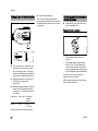
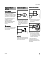
KombiSystem
Guide to Using this Manual
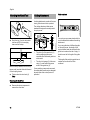
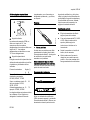
Pictograms
All the pictograms attached to or
embossed on the machine are shown
and explained in this manual.
+
Symbols in Text
Many operating and safety instructions
are supported by illustrations.
..
..
002BA530 KN
+
The individual steps or procedures
described in the manual may be marked
in different ways:
In the STIHL KombiSystem a number of
different KombiEngines and KombiTools
can be combined to produce a power
tool. In this instruction manual the
functional unit formed by the
KombiEngine and KombiTool is referred
to as the power tool.
Therefore, the separate instruction
manuals for the KombiEngine and
KombiTool should be used together for
the power tool.
Always read and and make sure you
understand both instruction manuals
before using your power tool for the first
time and keep them in a safe place for
future reference.
N
A bullet marks a step or procedure.
A description of a step or procedure that
refers directly to an illustration may
contain item numbers that appear in the
illustration. Example:
N
Loosen the screw (1).
N
Lever (2) ...
NOTICE
Indicates a risk of property damage,
including damage to the machine or its
individual components.
Engineering Improvements
STIHL’s philosophy is to continually
improve all of its products. As a result,
engineering changes and improvements
are made from time to time. Therefore,
some changes, modifications and
improvements may not be covered in
this manual. If the operating
characteristics or the appearance of
your machine differs from those
described in this manual, please contact
your STIHL dealer or the STIHL
distributor for your area for assistance.
In addition to the operating instructions,
this manual may contain paragraphs
that require your special attention. Such
paragraphs are marked with the
following symbols and signal words:
DANGER
Indicates an imminent risk of severe or
fatal injury.
WARNING
Indicates a hazardous situation which, if
not avoided, could result in severe or
fatal injury.
2
HT-KM
English
Safety Precautions and
Working Techniques
Because a KombiEngine
equipped with a pole
pruner KombiTool is a
high-speed, fast-cutting
power tool with a very
long reach, special safety
precautions must be
observed to reduce the
risk of personal injury.
It is important that you
read, fully understand
and observe the following
safety precautions and
warnings. Read the
instruction manuals and
the safety precautions for
your KombiEngine and
KombiTool periodically.
Careless or improper use
may cause serious or
fatal injury.
Have your STIHL dealer show you how
to operate your power tool. Observe all
applicable local safety regulations,
standards and ordinances.
WARNING
Do not lend or rent your power tool
without the instruction manuals for your
KombiEngine and KombiTool. Be sure
that anyone using it understands the
information contained in these manuals.
HT-KM
WARNING
The use of this machine may be
hazardous. The pole pruner chain has
many sharp cutters. If the cutters contact
your flesh, they will cut you, even if the
chain is not moving.
Do not cut any material other than wood
or wooden objects. Use your
KombiEngine equipped with the pole
pruner KombiTool for limbing only.
WARNING
Do not use it for other purposes, since
misuse may result in personal injury or
property damage, including damage to
the machine.
WARNING
Minors should never be allowed to use
this power tool. Bystanders, especially
children, and animals should not be
allowed in the area where it is in use.
WARNING
To reduce the risk of injury to bystanders
and damage to property, never let your
power tool run unattended. When it is
not in use (e.g. during a work break),
shut it off and make sure that
unauthorized persons do not use it.
Safe use of a power tool involves
1.
the operator
2.
the power tool
3.
the use of the power tool.
THE OPERATOR
Physical Condition
You must be in good physical condition
and mental health and not under the
influence of any substance (drugs,
alcohol, etc.) which might impair vision,
dexterity or judgment. Do not operate
this machine when you are fatigued.
WARNING
Be alert – if you get tired, take a break.
Tiredness may result in loss of control.
Working with any power tool can be
strenuous. If you have any condition that
might be aggravated by strenuous work,
check with your doctor before operating
this machine.
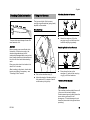
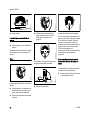
Proper Clothing
WARNING
To reduce the risk of injury, the operator
should wear proper protective apparel.
Most of these safety precautions and
warnings apply to the use of all STIHL
pole pruners. Different models may have
different parts and controls. See the
appropriate section of your
KombiEngine and KombiTool instruction
manuals for a description of the controls
and the function of the parts of your
model.
3
English
WARNING
To reduce the risk of
injury to your eyes never
operate your power tool
unless wearing goggles
or properly fitted protective glasses with
adequate top and side
protection complying with
ANSI Z87 "+" (or your
applicable national standard). To reduce the risk of
injury to your face STIHL
recommends that you
also wear a face shield or
face screen over your
goggles or protective
glasses.
Wear an approved safety
hard hat to reduce the
risk of injury to your head.
Power tool noise may
damage your hearing.
Wear sound barriers (ear
plugs or ear mufflers) to
protect your hearing.
Continual and regular
users should have their
hearing checked
regularly.
Be particularly alert and cautious when
wearing hearing protection because
your ability to hear warnings (shouts,
alarms, etc.) is restricted.
Always wear heavy duty
work gloves (e.g. made of
leather or other wear
resistant material) when
handling the machine
and the cutting tool.
Heavy-duty, nonslip
gloves improve your grip
and help to protect your
hands.
THE POWER TOOL (KOMBIENGINE
EQUIPPED WITH POLE PRUNER
KOMBITOOL)
Clothing must be sturdy
and snug-fitting, but allow
complete freedom of
movement. Wear long
pants made of heavy
material to help protect
your legs. Do not wear
shorts, sandals or go
barefoot.
Never modify this power tool in any way.
Only attachments supplied by STIHL or
expressly approved by STIHL for use
with the specific STIHL KombiEngine
are authorized. Although certain
unauthorized attachments are useable
with STIHL power tools, their use may,
in fact, be extremely dangerous.
Avoid loose-fitting jackets, scarfs,
neckties, jewelry, flared or cuffed pants,
unconfined long hair or anything that
could become caught on branches,
brush or the moving parts of the unit.
Secure hair so it is above shoulder level.
Good footing is very
important. Wear sturdy
boots with nonslip soles.
Steel-toed safety boots
are recommended.
For further instructions on proper
clothing see the safety precautions in
the instruction manual of the
KombiEngine you are using.
For illustrations and definitions of the
power tool parts see the chapter on
"Main Parts."
WARNING
If this tool is subjected to unusually high
loads for which it was not designed (e.g.
heavy impact or a fall), always check
that it is in good condition before
continuing work. Check in particular that
the fuel system is tight (no leaks) and
that the controls and safety devices are
working properly. Do not continue
operating this machine if it is damaged.
In case of doubt, have it checked by your
STIHL servicing dealer.
THE USE OF THE POWER TOOL
(KOMBIENGINE EQUIPPED WITH
POLE PRUNER KOMBITOOL)
Transporting the Power Tool
WARNING
Always switch off the engine and fit the
scabbard over the cutting attachment
before transporting the power tool over
long distances.
4
HT-KM
It may be carried only in a horizontal
position. Grip the shaft in a manner that
the machine is balanced horizontally.
Keep the hot muffler away from your
body and the cutting attachment behind
you. Accidental acceleration of the
engine can cause the chain to rotate and
cause serious injuries.
WARNING
When transporting it in a vehicle,
properly secure it to prevent turnover,
fuel spillage and damage to the unit.
Before Starting
Take off the chain guard (scabbard) and
inspect the pole pruner for proper
condition and operation. (See the
maintenance chart near the end of the
instruction manuals.)
WARNING
Always check your power tool for proper
condition and operation before starting.
Never attempt to modify the controls or
safety devices.
WARNING
Never operate your power tool if it is
damaged, improperly adjusted or
maintained, or not completely or
securely assembled.
HT-KM
Keep the handles clean and dry at all
times; it is particularly important to keep
them free of moisture, pitch, oil, fuel mix,
grease or resin in order for you to
maintain a firm grip and properly control
your power tool.
For specific starting instructions, see the
appropriate section of your
KombiEngine and KombiTool manuals.
For proper assembly of the bar and
chain follow the procedure described in
the chapter "Mounting the Bar and
Chain" of your instruction manual.
STIHL Oilomatic chain, guide bar and
sprocket must match each other in
gauge and pitch.
WARNING
Proper tension of the chain is extremely
important. In order to avoid improper
setting, the tensioning procedure must
be followed as described in your
manual. Always make sure the
hexagonal nut(s) for the sprocket cover
is (are) tightened securely after
tensioning the chain in order to secure
the bar. Never start the pole pruner with
the sprocket cover loose. Check chain
tension once more after having
tightened the nut(s) and thereafter at
regular intervals (whenever the pole
pruner is shut off). If the chain becomes
loose while cutting, shut off the engine
and then tighten. Never try to adjust the
chain while the engine is running!
Adjust harness and hand grip to suit
your size before starting work. To be
better prepared in case of an
emergency, practice releasing the unit
from the harness as quickly as possible.
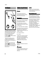
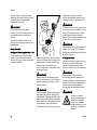
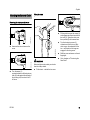
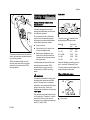
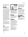
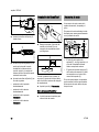
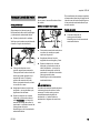
Starting
275BA006 KN
002BA254 KN
English
Place the pole pruner on firm ground or
other solid surface in an open area or, in
the alternative, as shown in the above
picture. Maintain good balance and
secure footing.
WARNING
To reduce the risk of injury from loss of
control, do not attempt to "drop start"
your power tool.
WARNING
To reduce the risk of injury from loss of
control be absolutely sure that the guide
bar and chain are clear of you and all
other obstructions and objects, including
the ground, because when the engine
starts at starting-throttle, engine speed
will be fast enough for the clutch to
engage the sprocket and move the
chain.
Once the engine has started,
immediately blip the throttle trigger,
which should release the starting throttle
and allow the engine to slow down to
idle.
Start the engine at least 10 feet (3 m)
from the fueling spot, outdoors only.
5
English
away fallen branches, scrub and
cuttings. Be extremely cautious when
working on slopes or uneven ground.
With the engine running only at idle,
attach the power tool to the spring hook
of your harness (see appropriate
chapter of this manual).
WARNING
WARNING
To reduce the risk of injury from loss of
control, never work on a ladder, in a tree
or any other insecure support. Never
hold the machine above shoulder
height. When working at a height above
15 feet (4.5 m) use a lift bucket.
Your power tool is a one-person
machine. Do not allow other persons in
the general work area, even when
starting.
See also the Safety Precautions on
Starting in the instruction manual of your
KombiEngine.
WARNING
473BA007 KN
During Operation
Holding and Controlling the Power Tool
Always hold the unit firmly with both
hands on the handles while you are
working. Wrap your fingers and thumbs
around the handles.
Place your left hand on the front handle
and your right hand on the rear grip and
throttle trigger. This also applies to lefthanders. Keep your hands in this
position to have your pole pruner under
control at all times.
WARNING
Never attempt to operate your power
tool with one hand. Loss of control of the
power tool resulting in serious or fatal
injury may result.
WARNING
Do not overreach. Keep proper footing
and balance at all times. Special care
must be taken in slippery conditions (wet
ground, snow) and in difficult, overgrown
terrain. Watch for hidden obstacles such
as tree stumps, roots and ditches to
avoid stumbling. For better footing, clear
6
Take extreme care in wet and freezing
weather (rain, snow, ice). Put off the
work when the weather is windy, stormy
or rainfall is heavy.
Working Conditions
Operate and start your power tool only
outdoors in a well-ventilated area.
Operate it under good visibility and
daylight conditions only. Work carefully.
WARNING
If the vegetation being cut or the
surrounding ground is coated with a
chemical substance (such as an active
pesticide or herbicide), read and follow
the instructions and warnings that
accompanied the substance at issue.
WARNING
Inhalation of certain
dusts, especially organic
dusts such as mold or
pollen, can cause susceptible persons to have
an allergic or asthmatic
reaction.
HT-KM
English
t)
0f
HT-KM
(5
Breathing asbestos dust is dangerous
and can cause severe or fatal illness,
respiratory illness or cancer. The use
and disposal of asbestos-containing
products have been strictly regulated by
OSHA and the Environmental Protection
Agency. If you have any reason to
believe that you might be cutting
asbestos, immediately contact your
employer or a local OSHA
representative.
m
WARNING
wet. Maintain a clearance of at least
50 feet (15 m) between the pole pruner
(including any branches it is contacting)
and any electrical line carrying live
current. Before working with less
clearance, contact your electric utility
and make sure the current is turned off.
15
Substantial or repeated inhalation of
dust and other airborne contaminants, in
particular those with a smaller particle
size, may cause respiratory or other
illnesses. This includes wood dust,
especially from hardwoods, but also
from some softwoods such as Western
Red Cedar. Control dust at the source
where possible. Use good work
practices, such as always cutting with a
properly sharpened chain (which
produces wood chips rather than fine
dust) and operating the unit so that the
wind or operating process directs any
dust raised by the power tool away from
the operator. Follow the
recommendations of EPA / OSHA /
NIOSH and occupational and trade
associations with respect to dust
("particulate matter"). When the
inhalation of dust cannot be
substantially controlled, i.e., kept at or
near the ambient (background) level, the
operator and any bystanders should
wear a respirator approved by NIOSH /
MSHA for the type of dust encountered.
Stop the engine immediately if you are
approached.
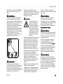
15m (50ft)
WARNING
This power tool has a large range. In
order to reduce the risk of personal or
even fatal injury to bystanders from
falling objects or inadvertent contact with
the moving chain of your power tool
always keep bystanders at least 50 feet
(15 m) away when the power tool is
running.
DANGER
Your power tool is not
insulated against electric
shock. To reduce the risk
of electrocution, never
operate this power tool in
the vicinity of any wires or
cables (power, etc.)
which may be carrying
electric current.
Electricity can jump from one point to
another by means of arcing. Higher
voltage increases the distance electricity
can arc. Electricity can also move
through branches, especially if they are
Make sure that the saw chain does not
touch any foreign materials such as
rocks, fences, nails and the like. Such
objects may be flung off and injure the
operator or bystanders, or damage the
saw chain.
WARNING
Even though bystanders should be kept
away from the running power tool, never
work alone. Keep within calling distance
of others in case help is needed.
Operating Instructions
WARNING
Do not operate your power tool using the
starting throttle lock, as you do not have
control of the engine speed.
In the event of an emergency, switch off
the engine immediately – move the slide
control / stop switch / momentary stop
switch to 0 or STOP.
See section of your KombiEngine
instruction manual on the proper use of
the slide control / stop switch /
momentary stop switch.
7
English
WARNING
To reduce the risk of cut injuries, keep
hands and feet away from the saw
chain. Never touch a moving chain with
your hand or any other part of your body.
The saw chain continues to move for a
short period after the throttle trigger is
released (inertia effect).
it could snap and fall toward the operator
while being cut. Also look for broken or
dead branches which could vibrate
loose and fall on the operator. If the
branch is thick or heavy, make a shallow
relief cut on the bottom of the branch
before cutting down from the top to help
prevent splitting of the branch.
Accelerating the engine while the chain
is blocked increases the load and will
cause the clutch to slip continuously.
This may result in overheating and
damage to important components (e.g.
clutch, polymer housing components) –
which can then increase the risk of injury
from the chain moving while the engine
is idling.
WARNING
max
473BA008 KN
If the chain becomes clogged, always
shut off the engine and make sure the
chain has stopped before cleaning.
WARNING
Keep work area clear – move away
fallen limbs. Place all tools and
equipment at a safe distance from the
branches being limbed, but not in the
escape area.
WARNING
Always observe the general condition of
the tree. Look for decay and rot in the
trunk and branches. If it is rotted inside,
8
Always pull the unit out of the cut with
the chain running to reduce the
possibility of pinching the cutting
attachment. Don't put pressure on the
pole pruner when reaching the end of a
cut. The pressure may cause the bar
and rotating chain to pop out of the cut or
kerf, go out of control and strike some
other object.
If the bar becomes pinched and caught
in the branch so that the chain can no
longer move, shut off the pole pruner
and carefully move the branch to open
the pinch and release the bar.
WARNING
Prior to limbing, clear the working area
from interfering limbs and brush. Then,
establish an escape area away from
where the cut limbs can fall, and remove
all obstacles.
WARNING
WARNING
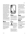
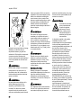
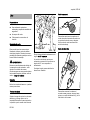
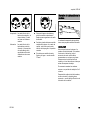
To reduce the risk of severe or even fatal
injury from falling objects do not cut
vertically above your body. Hold the pole
pruner at an angle of not more than 60°
from the horizontal level (see picture).
Objects may fall in unexpected
directions. Do not stand directly
underneath the limb being cut!
Watch for falling wood! As soon as the
limbed branch starts to fall, step aside
and keep a sufficient distance away from
the falling wood.
If a rotating saw chain strikes a rock or
other hard object, sparks may be
created, which can ignite flammable
materials under certain circumstances.
Flammable materials can include dry
vegetation and brush, particularly when
weather conditions are hot and dry.
When there is a risk of fire or wildfire, do
not use a power tool around flammable
materials or around dry vegetation or
brush. Contact your local fire authorities
or the U.S. Forestry Service if you have
any question about whether vegetation
and weather conditions are suitable for
the use of a pole pruner.
WARNING
The gearbox becomes hot during
operation. To reduce the risk of burn
injury, do not touch the gear housing
when it is hot.
HT-KM
English
a foreign object in the wood. The
reaction of the chain pulls the saw
forward.
Reactive Forces
Because of the design of the pole
pruner, the reactive forces experienced
when working with it are generally not as
severe as those encountered with a
chain saw. Nevertheless, you should
always maintain a proper grip and good
footing to control the power tool when
you experience such forces.
The reaction of the cutting force of the
chain causes a rotational force on the
pole pruner in the direction opposite to
the chain movement. This may cause
the bar to move upward.
To Avoid Kickback
To Avoid Pull-in
1.
Be alert to forces or situations that
may cause material to pinch the
chain at the bottom of the bar.
2.
Always start a cut with the chain
rotating at full speed.
B = Pushback
The best protection from kickback is to
avoid kickback situations:
1.
Be aware of the location of the guide
bar nose at all times
2.
Never let the nose of the guide bar
contact any object. Do not cut limbs
with the nose of the guide bar. Be
especially careful near wire fences
and when cutting small, tough
limbs, which may easily catch the
chain.
The most common reactive forces are:
–
kickback,
–
pushback,
3.
–
pull-in.
A = Pull-in
Cut only one limb at a time.
Kickback
Kickback may occur when the moving
saw chain near the upper quadrant of
the bar nose contacts a solid object or is
pinched.
B
Pushback occurs when the chain on the
top of the bar is suddenly stopped when
it is pinched, caught or encounters a
foreign object in the wood. The reaction
of the chain may drive the saw rapidly
straight back toward the operator.
Pushback frequently occurs when the
top of the bar is used for cutting.
001BA037 KN
To Avoid Pushback
A
Pull-in occurs when the chain on the
bottom of the bar is suddenly stopped
when it is pinched, caught or encounters
HT-KM
Pull-in frequently occurs when the chain
is not rotating at full speed before it
contacts the wood.
001BA038 KN
Reactive forces may occur any time the
chain is rotating.The force used to cut
wood can be reversed and work against
the operator. If the rotating chain is
suddenly stopped by contact with any
solid object such as a branch or is
pinched, the reactive forces may occur
instantly. These reactive forces may
result in loss of control, which, in turn,
may cause personal injury. An
understanding of the causes of these
reactive forces may help you avoid the
element of surprise and loss of control.
002BA230 KN
WARNING
1.
Be alert to forces or situations that
may cause material to pinch the
chain at the top of the bar.
2.
Do not cut more than one limb at a
time.
3.
Do not twist the bar when
withdrawing it from an underbuck
cut because the chain can pinch.
9
English
MAINTENANCE, REPAIR AND
STORING
WARNING
Always stop the engine and make sure
that the chain is stopped before doing
any maintenance or repair work or
cleaning the power tool. Do not attempt
any maintenance or repair work not
described in your KombiEngine and
KombiTool instruction manuals. Have
such work performed by your STIHL
servicing dealer only.
WARNING
Use only identical STIHL replacement
parts for maintenance and repair. Use of
non-STIHL parts may cause serious or
fatal injury.
Wear gloves when handling or
performing maintenance on the bar and
chain.
WARNING
Keep the chain, bar and sprocket clean;
replace worn sprockets or chains. Keep
the chain sharp. You can spot a dull
chain when easy-to-cut wood becomes
hard to cut or burn marks appear on the
wood.
Tighten all nuts, bolts and screws except
the carburetor adjustment screws after
each use.
Do not clean your machine with a
pressure washer. The solid jet of water
may damage parts of the machine.
Store chain oil in approved and properly
labeled safety-type canisters only. Avoid
direct contact with the skin!
Using the Unit
Preparations
N
Wear suitable protective clothing,
observe safety precautions.
N
Starting the engine
N
Put on the shoulder strap.
Cutting sequence
To allow branches a free fall, always cut
the lower branches first. Prune heavy
branches (large diameter) in several
controllable pieces.
WARNING
Never stand directly underneath the
branch you are cutting – be wary of
falling branches. Note that a branch may
spring back at you after it hits the ground
– risk of injury.
Disposal
Do not throw cuttings into the garbage
can – they can be composted.
Working Technique
Hold the control handle with your right
hand, and the loop handle with your left
hand. Your left arm should be extended
to the most comfortable position.
Store the power tool in a dry and high or
locked location out of reach of children.
10
HT-KM
English
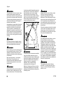
Flush-cutting thick branches
Relieving cut
A
2
The least tiring working position is a tool
angle of 60°.
Any lesser angle may be used to suit the
situation concerned.
3
390BA024 KN
The shaft should always be held at an
angle of 60° or less.
4
390BA041 KN
402BA012 KN
1
To avoid tearing the bark on thick
branches, always start by performing a
relieving cut (1) on the underside of the
branch.
N
To do this, apply the cutting
attachment and pull it across the
bottom of the branch in an arc as far
as the bar nose.
N
Then position the bar with the hook
against the branch and perform the
cross-cut (2).
N
perform an initial cut (3), with
relieving cut and cross-cut at
distance (A) of about 8 in (20 cm)
from the final cut, then carry out the
flush-cut (4), starting with a relieving
cut and finishing with a cross-cut.
390BA052 KN
Cross-cut
If branch diameter is more than
4 in (10 cm), first
To avoid pinching the bar in the cut,
position the cutting attachment with the
hook against the branch and then
perform the cross-cut from the top
downwards.
HT-KM
11
English
Cutting above obstacles
30° angle drive (special accessory)
Approved KombiEngines
KombiEngines
1
Only KombiEngines supplied by STIHL
or expressly approved by STIHL for use
with the specific model are authorized.
Only use this KombiTool with the
following KombiEngines:
STIHL KM 55 R, KM 56 R, KM 85 R,
KM 90 R, KM 94 R, KM 110 R,
KM 130 R
402BA013 KN
2
Cutting from a lift bucket
390BA053 KN
The unit's long reach makes it possible
to prune branches that are overhanging
obstacles, such as rivers or lakes. The
tool angle in this case depends on the
position of the branch.
WARNING
For machines with a loop handle, the clip
(barrier bar) must be installed.
The angle drive keeps the cutting
attachment at an angle of 30° to the
drive tube.
The angle drive may be adjusted on the
drive tube to the following positions only:
1
402BA032 KN
2
For cross-cutting vertical branches
and bushes.
For a better view of the cutting
attachment.
The unit's long reach enables cutting to
be performed next to the trunk without
the risk of the lift bucket damaging other
branches. The tool angle in this case
depends on the position of the branch.
12
HT-KM
English
Mounting the Gearbox
Assembling the Unit
3
402BA024 KN
1
A
413BA014 KN
402BA002 KN
3
Pull the protective caps off the ends
of the drive tube and keep them in a
safe place for later use – see
"Storing the Machine".
N
Apply a mark at distance A (2 in,/
50 mm) from the end of the drive
tube.
NOTICE
The plug may come out of the drive tube
when you pull off the cap. Push it back
into the drive tube as far as stop.
HT-KM
1
1
402BA023 KN
002BA248 KN
2
N
Insert the clamp screws (3) as far as
stop.
402BA035 KN
N
N
Push the gearbox (1) onto the drive
tube as far as stop – turn the
gearbox back and forth until the
square end of the shaft engages.
The gearbox is correctly positioned
when the end of its housing reaches or
covers the mark (arrow).
N
Line up the gearbox (1) so that the
chain sprocket cover is exactly
vertical and the lug (arrow) on the
end of the drive tube faces up.
N
Tighten down the clamp screws (3)
in the following sequence:
–
tighten the left screw moderately
–
tighten the right screw moderately
–
tighten down the left screw firmly
–
tighten down the right screw firmly
13
English
Mounting the KombiTool
A cutting attachment consists of the saw
chain, guide bar and chain sprocket.
1
N
1
Push the lug (1) on the drive tube
into the slot (2) in the coupling
sleeve as far as stop.
002BA327 KN
4
When correctly installed, the red line (3)
(arrow point) must be flush with the end
of the coupling sleeve.
N
Tighten down the star knob (4)
firmly.
2
a
3
001BA244 KN
002BA326 KN
The cutting attachment that comes
standard is designed to exactly match
the pole pruner.
3
001BA248 KN
2
Chain scabbard
Cutting Attachment
–
The pitch (t) of the saw chain (1),
chain sprocket and the nose
sprocket of the Rollomatic guide bar
must match.
–
The drive link gauge (2) of the saw
chain (1) must match the groove
width of the guide bar (3).
Your pole pruner comes standard with a
chain scabbard that matches the cutting
attachment.
If you use guide bars of different lenghts
on the pole pruner, the length of the
chain scabbard must be matched to the
guide bar to reduce the risk of injury. It
should cover the full length of the guide
bar.
The length of the matching guide bars is
marked on the side of the chain
scabbard.
If non-matching components are used,
the cutting attachment may be damaged
beyond repair after a short period of
operation.
Removing the KombiTool
N
14
Reverse the above sequence to
remove the drive tube.
HT-KM
English
Fitting the chain
5
Removing the chain sprocket cover
4
390BA042 KN
Unscrew the nut and remove the
cover.
390BA003 KN
N
1
N
WARNING
390BA043 KN
2
Turn the screw (1)
counterclockwise until the tensioner
slide (2) butts against the left end of
the housing slot, then back it off 5
full turns.
HT-KM
1
3
390BA044 KN
Mounting the Bar and Chain
N
Fit the guide bar over the screw (3)
and engage peg of tensioner slide in
the hole (4) – place the chain over
the sprocket (5) at the same time.
N
Turn the tensioning screw (1)
clockwise until there is very little
chain sag on the underside of the
bar – and the drive link tangs are
engaged in the bar groove.
N
Refit the cover and screw on the nut
fingertight.
N
Go to chapter on "Tensioning the
Saw Chain"
Wear work gloves to protect your hands
from the sharp cutters.
N
Fit the chain – start at the bar nose.
15
English
Retensioning during cutting work:
N
Stopping the engine
N
Loosen the nut.
N
Hold the bar nose up.
N
Use a screwdriver to turn the
tensioning screw (1) clockwise until
the chain fits snugly against the
underside of the bar.
N
While still holding the bar nose up,
tighten down the nut firmly.
N
Go to "Checking Chain Tension".
A new chain has to be retensioned more
often than one that has been in use for
some time.
N
16
Check chain tension frequently –
see chapter on "Operating
Instructions".
Chain Lubricant
390BA046 KN
1
Checking Chain Tension
390BA045 KN
Tensioning the Chain
N
Shut off the engine
N
Wear work gloves to protect your
hands.
N
The chain must fit snugly against
the underside of the bar and it must
still be possible to pull the chain
along the bar by hand.
N
If necessary, retension the chain.
A new chain has to be retensioned more
often than one that has been in use for
some time.
N
Check chain tension frequently –
see chapter on "Operating
Instructions".
For automatic and reliable lubrication of
the chain and guide bar – use only an
environmentally compatible quality
chain and bar lubricant. Rapidly
biodegradable STIHL BioPlus is
recommended.
NOTICE
Biological chain oil must be resistant to
aging (e.g. STIHL BioPlus), since it will
otherwise quickly turn to resin. This
results in hard deposits that are difficult
to remove, especially in the area of the
chain drive and chain. It may even cause
the oil pump to seize.
The service life of the chain and guide
bar depends on the quality of the
lubricant. It is therefore essential to use
only a specially formulated chain
lubricant.
WARNING
Do not use waste oil. Renewed contact
with waste oil can cause skin cancer.
Moreover, waste oil is environmentally
harmful.
NOTICE
Waste oil does not have the necessary
lubricating properties and is unsuitable
for chain lubrication.
HT-KM
English
A full chain oil tank is sufficient for only
half a tankful of fuel. Check the oil level
regularly during cutting work. Never
allow the oil tank to run dry.
002BA575 KN
NOTICE
N
002BA578 KN
Opening
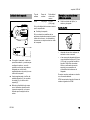
Filling Chain Oil Tank
N
Remove the cap.
Filling up with chain oil
Raise the grip until it is upright.
Preparations
N
Filling up with chain oil
Thoroughly clean the oil filler cap
and the area around it to ensure that
no dirt falls into the tank.
N
Position the machine so that the
filler cap faces up.
Turn the cap counterclockwise
(about a quarter turn).
Marks on filler cap and oil tank must line
up.
HT-KM
Closing
002BA577 KN
N
N
002BA577 KN
390BA047 KN
002BA576 KN
Take care not to spill chain oil while
refilling and do not overfill the tank.
Grip must be vertical:
N
Fit the cap – marks on filler cap and
oil tank must line up.
N
Press the cap down as far as stop.
17
English
If the oil level in the tank does not go
down, the reason may be a fault in the oil
supply system: Check chain lubrication,
clean the oilways, contact your dealer
for assistance if necessary STIHL
recommends that you have servicing
and repair work carried out exclusively
by an authorized STIHL servicing
dealer.
Left:
Right:
Bottom of cap is twisted –
inner mark (1) in line with
outer mark.
Bottom of cap in correct position – inner mark is under the
grip. It is not in line with the
outer mark.
If the filler cap cannot be locked in the oil
tank opening
002BA576 KN
The marks on the filler cap and oil tank
are then in alignment.
Filler cap is locked.
002BA584 KN
002BA583 KN
002BA579 KN
While holding the cap depressed,
turn it clockwise until it engages in
position.
002BA580 KN
N
1
Bottom of cap is twisted in relation to
top.
002BA581 KN
N
N
18
Remove the cap from the oil tank
and check it from above.
N
Place the cap on the opening and
rotate it counterclockwise until it
engages the filler neck.
N
Continue rotating the cap
counterclockwise (about a quarter
turn) – this causes the bottom of the
cap to be turned to the correct
position.
N
Turn the cap clockwise and lock it in
position – see section on "Closing".
Fold the grip down.
HT-KM
English
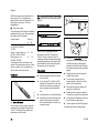
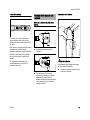
Attaching Machine to Harness
Fitting the Harness
The type and style of the harness,
carrying ring and carabiner (spring hook)
depend on the market.
1
Shoulder Strap
1
N
1
NOTICE
002BA308 KN
390BA048 KN
2
The saw chain must always throw off a
small amount of oil.
Attach the carabiner (1) to the
carrying ring (2) on the drive tube –
hold the carrying ring steady.
Detaching Machine from Harness
Never operate your saw without chain
lubrication. If the chain runs dry, the
whole cutting attachment will be
irretrievably damaged within a very short
time. Always check chain lubrication and
the oil level in the tank before starting
work.
1
2
2
002BA374 KN
Every new chain has to be broken in for
about 2 to 3 minutes.
After breaking in the chain, check chain
tension and adjust if necessary – see
"Checking Chain Tension".
2
N
Put on the shoulder strap (1).
N
Adjust the length of the strap so that
the carabiner (2) is about a hand’s
width below your right hip.
N
1
2
002BA310 KN
Checking Chain Lubrication
Press down the bar on the
carabiner (1) and pull the carrying
ring (2) out of the carabiner.
Throwing Off the Machine
WARNING
The machine must be quickly thrown off
in the event of imminent danger.
Practice removing and putting down the
power tool as you would in an
emergency. To avoid damage, do not
throw the power tool to the ground when
practicing.
HT-KM
19
English
Practice slipping the strap off your
shoulder.
Alternative method of starting
Starting / Stopping the
Engine
Starting the Engine
Always follow the operating instructions
for the KombiEngine and basic power
tool.
N
402BA034 KN
Practice quickly detaching the power
tool from the carabiner as described
under "Detaching Machine from
Harness".
Remove the chain guard.
N
Hang the cutting attachment on a
branch so that it is held by the hook.
N
Make sure you have a safe and
secure footing.
N
Hold the machine with you left hand
and press it down firmly – do not
touch the controls on the control
handle – see KombiEngine or basic
power tool instruction manual.
402BA033 KN
Check that the chain is not touching the
ground or any other obstacles.
N
Position the unit securely for
starting: Put the powerhead on the
ground so that it rests on the engine
support. Rest the hook on the
cutting attachment on a raised
support, e.g. a mound or branch.
N
Make sure you have a firm footing,
either standing, stooping or
kneeling.
N
Hold the machine with you left hand
and press it down firmly – do not
touch the controls on the control
handle – see KombiEngine or basic
power tool instruction manual.
WARNING
The saw chain may begin to run as soon
as the engine starts. For this reason, blip
the throttle after starting – the engine
returns to idling speed.
The starting procedure is now as
described in the instruction manual of
the KombiEngine or basic power tool
you are using.
Stopping the Engine
N
See KombiEngine or basic power
tool instruction manual.
NOTICE
Do not stand or kneel on the drive tube.
20
HT-KM
English
Operating Instructions
During Operation
Check chain tension frequently
A new chain has to be retensioned more
often than one that has been in use for
some time.
Chain cold
Tension is correct when the chain fits
snugly against the underside of the bar
and can still be pulled along the bar by
hand. Retension if necessary – see
"Tensioning the Saw Chain".
Chain at operating temperature
The chain stretches and begins to sag.
The drive links must not come out of the
bar groove – the chain may otherwise
jump off the bar. Retension the chain –
see "Tensioning the Saw Chain".
NOTICE
Always slacken off the chain after
finishing work. The chain contracts as it
cools down. If it is not slackened off, it
can damage the gear shaft and
bearings.
Storing for a long period
See chapter on "Storing the Machine"
Storing the Machine
For periods of 3 months or longer
N
Remove the saw chain and guide
bar, clean them and spray with
corrosion inhibiting oil.
N
If you use a biological chain and bar
lubricant, e.g. STIHL BioPlus,
completely fill the chain oil tank.
N
If the KombiTool is removed from
the KombiEngine and stored
separately: Fit the protective cap on
the drive tube to avoid dirt getting
into the coupling.
N
Store the machine in a dry, high or
locked location – out of the reach of
children and other unauthorized
persons.
NOTICE
The chain contracts as it cools down. If it
is not slackened off, it can damage the
gear shaft and bearings.
After Finishing Work
N
Slacken off the chain if you have
retensioned it at operating
temperature during cutting work.
HT-KM
21
English
Taking Care of the Guide Bar
N
Replace the guide bar.
The drive link tangs will otherwise
scrape along the bottom of the groove –
the cutters and tie straps will not ride on
the bar rails.
Checking and Replacing the
Chain Sprocket
N
Remove the chain sprocket cover,
chain and guide bar.
Replace the chain sprocket
2
1
N
3
390BA050 KN
000BA054 KN
a
Turn the bar over – every time you
sharpen the chain and every time
you replace the chain – this helps
avoid one-sided wear, especially at
the nose and underside of the bar.
N
Regularly clean the oil inlet hole (1),
the oilway (2) and the bar
groove (3).
N
Measure the groove depth – with the
scale on the filing gauge (special
accessory) – in the area used most
for cutting.
Chain type
Picco
–
after using two saw chains or
sooner
–
if the wear marks (a) are deeper
than 0.02 in (0.5 mm) since this
would reduce the life of the chain.
Use a gauge (special accessory) to
check the depth of the wear marks.
It is best to use two saw chains in
rotation with one sprocket.
STIHL recommends the use of original
STIHL chain sprockets.
Chain pitch Minimum
groove
depth
3/8" P
0.20"
(5.0 mm)
If groove depth is less than specified:
22
HT-KM
English
Chain pitch
Cutting effortlessly with a correctly
sharpened chain
a
Do not work with a dull or damaged
chain as it will increase the physical
effort required, produce unsatisfactory
results and a higher rate of wear.
The chain sprocket is driven via a friction
clutch. Have the chain sprocket replaced
by a servicing dealer.
STIHL recommends that you have
servicing and repair work carried out
exclusively by an authorized STIHL
servicing dealer.
N
Clean the chain.
N
Check the chain for cracks in the
links and damaged rivets.
N
Replace any damaged or worn
parts of the chain and match the
new parts to the shape and size of
the original parts.
Carbide-tipped saw chains (Duro) are
particularly wear resistant. STIHL
recommends you have your chain
resharpened by a STIHL servicing
dealer.
WARNING
689BA027 KN
A properly sharpened chain slices
through wood effortlessly and requires
very little feed pressure.
The chain pitch (a) is marked on the
depth gauge end of each cutter.
Mark (a)
7
1 or 1/4
6, P or PM
2 or 325
3 or 3/8
Select file diameter according to chain
pitch – see table “Sharpening Tools”.
You must observe certain angles when
resharpening the chain cutter.
Filing and side plate angles
It is absolutely essential to comply with
the angles and dimensions specified
below. If the saw chain is incorrectly
sharpened – and in particular if the depth
gauge is set too low – there is an
increased risk of kickback, with resulting
risk of injury.
The saw chain cannot be locked in place
on the guide bar. Therefore, it is best to
remove the chain from the bar and
resharpen it on a workshop sharpening
tool (FG 2, HOS, USG).
HT-KM
Chain pitch
inch
mm
1/4 P
6,35
1/4
6,35
3/8 P
9,32
0.325
8,25
3/8
9,32
A
B
A
689BA021 KN
Maintaining and Sharpening
the Saw Chain
Filing angle
23
English
B
Use only special saw chain sharpening
files. Other files have the wrong shape
and cut.
For checking angles
Side plate angle
90°
The correct side plate angle is obtained
automatically if you use the prescribed
file holder and file diameter.
Cutter shapes
The angles must be the same on all
cutters. If the angles are uneven: Chain
will run roughly, not in a straight line,
wear quickly and finally break.
File holder
Use a STlHL filing gauge (special
accessory, see table "Sharpening
Tools"). This is a universal tool for
checking the filing and side plate angles,
depth gauge setting, cutter length and
groove depth. It also cleans the guide
bar groove and oil inlet holes.
N
689BA025 KN
Use a file holder
A file holder must be used for manual
resharpening (see table "Sharpening
Tools"). The correct filing angles are
marked on the file holder.
24
N
Hold the file horizontally (at a right
angle to the side of the guide bar)
and file according to the angles
marked on the file holder. Rest the
file holder on the top plate and depth
gauge.
N
Always file from the inside to the
outside of the cutter.
N
The file only sharpens on the
forward stroke – lift the file off the
cutter on the backstroke.
N
Avoid touching the tie straps and
drive links with the file.
N
Rotate the file at regular intervals
while filing to avoid one-sided wear.
N
Use a piece of hardwood to remove
burrs from the cutting edge.
N
Check angles with the filing gauge.
File correctly
N
N
689BA043 KN
001BA203 KN
Angle (°)
A
B
Micro = semi chisel cutter, 30
75
e.g. 63 PM3, 26 RM3,
71 PM3
Super = chisel cutter, e.g. 30
60
63 PS3, 26 RS, 36 RS3
Ripping chain, e.g.
10
75
63 PMX, 36 RMX
689BA018 KN
STIHL saw chains are sharpened to a
filing angle of 30°. Exceptions are
ripping chains with a filing angle of 10°.
Ripping chains have an X in their
designations.
Select sharpening tools according
to chain pitch.
If you use an FG 2, HOS or USG
sharpener: Remove the chain from
the bar and sharpen according to
the instructions supplied with the
tool.
N
Clamp the bar in a vise if necessary.
N
Sharpen the chain frequently, take
away as little metal as possible –
two or three strokes of the file are
usually enough.
All cutters must be the same length.
HT-KM
English
If the cutters are not the same length,
they will have different heights. This
makes the chain run roughly and can
cause it to break.
N
Use a filing gauge to check the
setting every time you sharpen the
chain.
Depth gauge setting
689BA023 KN
a
The depth gauge determines the height
at which the cutter enters the wood and
thus the thickness of the chip removed.
a
Specified distance or setting
between depth gauge and cutting
edge.
This setting may be increased by 0.2
mm (0.008") for cutting softwood in the
mild weather season – no frost.
Chain pitch
inch
1/4 P
1/4
3/8 P
0.325
3/8
HT-KM
(mm)
(6,35)
(6,35)
(9,32)
(8,25)
(9,32)
Depth gauge
Setting (a)
mm
(inch)
0,45
(0.018)
0,65
(0.026)
0,65
(0.026)
0,65
(0.026)
0,65
(0.026)
N
N
File down the depth gauge until it is
level with the filing gauge.
N
File the top of the depth gauge
parallel to the stamped service
marking (see arrow) – but do not
lower the highest point of the depth
gauge in this process.
2
689BA061 KN
1
689BA051 KN
Find the shortest cutter and then file
all other cutters back to the same
length. It is best to have this work
done by a servicing dealer on an
electric grinder.
The depth gauge setting is reduced
when the chain is sharpened.
Place a filing gauge (1) that
matches the chain pitch on the
chain and press it against the cutter
– if the depth gauge projects from
the filing gauge, the depth gauge
has to be lowered.
Saw chains with humped drive link (2) –
upper part of humped drive link (2) (with
service mark) is lowered along with the
depth gauge.
WARNING
The other parts of the humped drive link
must not be filed since this may increase
the kickback tendency of the power tool.
689BA044 KN
N
Lowering depth gauges
WARNING
The kickback tendency of the machine is
increased if the depth gauges are too
low.
25
689BA052 KN
English
N
N
After sharpening, clean the chain
thoroughly, remove filings or
grinding dust – lubricate the chain
thoroughly.
N
Before a long out-of-service period,
clean the chain and store it in a welloiled condition.
Place the filing gauge on the chain –
the highest point of the depth gauge
must be level with the filing gauge.
Sharpening Tools (special accessories)
Chain pitch
Round file ^ Round file
File holder
inch
(mm)
mm (inch)
Part No.
Part No.
1/4 P
(6,35) 3,2 (1/8)
5605 771 3206
5605 750 4300
1/4
(6,35) 4,0 (5/32)
5605 772 4006
5605 750 4327
3/8 P
(9,32) 4,0 (5/32)
5605 772 4006
5605 750 4327
0.325
(8,25) 4,8 (3/16)
5605 772 4806
5605 750 4328
3/8
(9,32) 5,2 (13/64) 5605 772 5206
5605 750 4329
1) consisting of file holder with round file, flat file and filing gauge
26
Filing gauge
Part No.
0000 893 4005
1110 893 4000
1110 893 4000
1110 893 4000
1110 893 4000
Flat file
Part No.
0814 252 3356
0814 252 3356
0814 252 3356
0814 252 3356
0814 252 3356
Sharpening kit 1)
Part No.
5605 007 1000
5605 007 1027
5605 007 1027
5605 007 1028
5605 007 1029
HT-KM
English
All accessible screws and nuts (not adjustRetighten
ing screws)
X
Chain lubrication
Check
X
Inspect, also check sharpness
X
X
Saw chain
Check chain tension
X
X
Sharpen
Check (wear, damage)
Guide bar
X
X
Clean and turn over
X
Deburr
X
Replace
Chain sprocket
Safety labels
1)
Check
X
X
X
X
Have replaced by dealer1)
Replace
if required
if damaged
if problem
every 12 months
monthly
weekly
after each refueling stop
after finishing work or daily
The following intervals apply to normal operating conditions only. If your daily working time is longer or operating conditions are difficult (very dusty work area, resinrich wood, tropical wood, etc.), shorten the specified intervals accordingly. If you only
use the saw occasionally, extend the intervals accordingly.
before starting work
Maintenance and Care
X
X
STIHL recommends a STIHL servicing dealer.
HT-KM
27
English
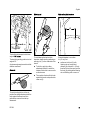
Main Parts
4
1
5
3
2
11
12
5
8
6
10
7
Oilomatic Saw Chain
Guide Bar
Oil Tank
Oil Filler Cap
Drive Tube
Chain Sprocket Cover
Hook
Chain Guard (Scabbard)
Chain Sprocket
Chain Tensioner
Sleeve
Handle Hose
473BA006 KN
9
1
2
3
4
5
6
7
8
9
10
11
12
28
HT-KM
English
Definitions
1
Saw chain 3/8" P
Specifications
Low kickback STIHL saw chain (with
green label)
Picco Micro Mini 3 (61 PMM3)
Type 3610
Pitch:
3/8" P (9.32 mm)
Drive link gauge: 1.1 mm (0.043 in.)
Oilomatic Saw Chain
A loop consisting of cutters, tie
straps and drive links.
Chain Lubrication
2
Guide Bar
Supports and guides the saw chain.
Fully automatic, speed-controlled oil
pump with rotary piston
3
Oil Tank
Tank for chain lubricating oil.
Oil tank capacity:
4
Oil Filler Cap
For closing the oil tank.
Weight
6-tooth for 3/8" P
7-tooth for 3/8" P
5
Drive Tube
Encloses and protects the drive
shaft between the coupling sleeve
and gearbox.
Cutting attachment
with drive tube:
Since new bar/chain combinations may
be developed after publication of this
Manual, ask your STIHL dealer for the
latest STIHL recommendations.
6
Chain Sprocket Cover
Covers the sprocket.
7
Hook
For hooking machine to a branch
and pulling branches away.
8
Chain Guard (Scabbard)
To protect the operator from
touching the chain.
9
Chain Sprocket
The toothed wheel that drives the
saw chain.
10 Chain Tensioner
Permits precise adjustment of chain
tension.
11 Sleeve
Locates drive tube in coupling
sleeve.
12 Handle Hose
For holding and controlling the unit
with the hand during operation.
HT-KM
0.22 l (7.4 fl.oz)
1.8 kg (4.2 lbs)
Cutting attachments
Chain sprocket
Rollomatic E Mini guide bar
Reduced kickback STIHL guide bars
(with green label)
Bar lengths:
30 cm (12 in.)
Pitch:
3/8" P (9.32 mm)
Groove width: 1.1 mm (0.043 in.)
Actual cutting length will be less than
listed bar length.
Rollomatic E Mini Light guide bars
Reduced kickback STIHL guide bars
(with green label)
Bar lengths:
25, 30 cm (10, 12 in.)
Pitch:
3/8" P (9.32 mm)
Groove width: 1.1 mm (0.043 in.)
Actual cutting length will be less than
listed bar length.
29
English
Users of this unit should carry out only
the maintenance operations described
in this manual. STIHL recommends that
other repair work be performed only by
authorized STIHL servicing dealers.
Warranty claims following repairs can be
accepted only if the repair has been
performed by an authorized STIHL
servicing dealer using genuine STIHL
replacement parts.
Genuine STIHL parts can be identified
by the STIHL part number, the
{ logo and, in some cases, by
the STIHL parts symbol K. The
symbol may appear alone on small
parts.
Disposal
Trademarks
Observe all country-specific waste
disposal rules and regulations.
STIHL Registered Trademarks
STIHL®
{
K
000BA073 KN
Maintenance and Repairs
The color combination orange-grey
(U.S. Registrations #2,821,860;
#3,010,057, #3,010,058, #3,400,477;
and #3,400,476)
STIHL products must not be thrown in
the garbage can. Take the product,
accessories and packaging to an
approved disposal site for environmentfriendly recycling.
Contact your STIHL servicing dealer for
the latest information on waste disposal.
AUTOCUT®
EASYSTART®
FARM BOSS®
iCademy®
MAGNUM®
MasterWrench Service®
MotoMix®
30
HT-KM
English
OILOMATIC®
Quad Power ™
®
Quiet Line ™
ROCK BOSS
STIHL
Cutquik®
STIHL Arctic ™
®
STIHL DUROMATIC
®
STIHL HomeScaper Series ™
STIHL Quickstop
STIHL
STIHL Compact ™
ROLLOMATIC®
®
STIHL WOOD BOSS
TIMBERSPORTS®
STIHL Interchangeable Attachment
Series ™
STIHL M-Tronic ™
STIHL MiniBoss ™
WOOD BOSS®
YARD BOSS®
STIHL MotoPlus 4 ™
Some of STIHL’s Common Law
Trademarks
STIHL OUTFITTERS ™
STIHL Multi-Cut HomeScaper Series ™
STIHL PICCO ™
STIHL PolyCut ™
STIHL
Injection
STIHL PowerSweep ™
TM
STIHL Precision Series ™
STIHL Protech ™
STIHL RAPID ™
STIHL SuperCut ™
4-MIX ™
STIHL Territory ™
BioPlus ™
TapAction ™
Easy2Start ™
TrimCut ™
EasySpool ™
This listing of trademarks is subject to
change.
ElastoStart ™
Ematic ™
FixCut ™
HT Plus ™
IntelliCarb ™
Any unauthorized use of these
trademarks without the express written
consent of
ANDREAS STIHL AG & Co. KG,
Waiblingen is strictly prohibited.
Master Control Lever ™
Micro ™
Pro Mark ™
HT-KM
31
español / EE.UU
Contenido
34
43
45
45
46
46
47
48
48
49
49
51
52
53
54
54
55
55
56
60
61
62
63
63
64
Permita que solamente las personas
que comprenden la materia tratada en
los manuales del motor KombiEngine y
del podador de varilla KombiTool
manejen esta herramienta motorizada
combinada.
Para obtener el rendimiento y
satisfacción máximos de la herramienta
KombiTool de STIHL, es importante que
lea, obedezca y comprenda las
precauciones de seguridad y las
instrucciones de uso y mantenimiento
dadas en el capítulo "Precauciones de
seguridad y técnicas de uso", antes de
usar la KombiTool. Para información
adicional, puede acudir a
www.stihlusa.com.
Comuníquese con el concesionario o
distribuidor de STIHL si no se entiende
alguna de las instrucciones dadas en los
dos manuales.
ADVERTENCIA
Dado que este motor KombiEngine
equipado con podador de varilla
KombiTool tiene un accesorio de corte
de gran velocidad, es necesario tomar
medidas especiales de seguridad para
reducir el riesgo de lesiones. El uso
descuidado o inadecuado puede causar
lesiones graves e incluso mortales.
Este manual de instrucciones está protegido por derechos de propiedad intelectual. Todos los derechos reservados, especialmente los derechos de reproducción, traducción y procesamiento con sistemas electrónicos.
HT-KM
Manual de instrucciones original
32
33
Marcas comerciales
© ANDREAS STIHL AG & Co. KG, 2015
0458-473-8621-B. VA0.C15.
0000000494_005_EA
{
33
Impreso en papel libre de cloro.
Las tintas contienen aceites vegetales, el papel es reciclable.
Sistema KombiSystem
Acerca de este manual de
instrucciones
Medidas de seguridad y técnicas
de manejo
Uso
Motores KombiEngine aprobados
Armado de la máquina
Instalación del KombiTool
Accesorio de corte
Montaje de la espada y la cadena
Tensado de la cadena
Revisión de tensión de la cadena
Lubricante de cadena
Llenado del tanque de aceite de la
cadena
Revisión de lubricación de la
cadena
Uso de la correa para hombro
Arranque / parada del motor
Instrucciones para el uso
Almacenamiento de la máquina
Cuidado de la espada
Revisión y sustitución del piñón de
cadena
Mantenimiento y afilado de la
cadena de aserrado
Información para mantenimiento
Componentes importantes
Especificaciones
Información de reparación
Desecho
español / EE.UU
Sistema KombiSystem
Acerca de este manual de
instrucciones
Pictogramas
+
+
002BA530 KN
..
..
Con el sistema KombiSystem de STIHL,
varios motores KombiEngine y
accesorios KombiTool pueden
combinarse para formar una
herramienta motorizada. En este
manual de instrucciones la unidad
formada por el motor KombiEngine y la
herramienta KombiTool se identifica
como la herramienta motorizada.
Por lo tanto, para esta herramienta
motorizada es necesario usar juntos los
manuales de instrucciones para el motor
KombiEngine y la herramienta
KombiTool.
Siempre lea y entienda los dos
manuales de instrucciones antes de
usar la herramienta motorizada por
primera vez y guarde los mismos en un
lugar seguro para referencia futura.
HT-KM
ADVERTENCIA
Identifica una situación de peligro que,
al no evitarse, puede resultar en
lesiones graves o mortales.
Todos los pictogramas que se
encuentran fijados o grabados en la
máquina se muestran y explican en este
manual.
INDICACIÓN
Símbolos en el texto
Mejoramientos técnicos
Muchas de las instrucciones de uso y
seguridad vienen acompañadas de
ilustraciones.
La filosofía de STIHL es mejorar
continuamente todos sus productos.
Como resultado de ello, periódicamente
se introducen cambios de diseño y
mejoras. Por lo tanto, es posible que
algunos cambios, modificaciones y
mejoras no se describen en este
manual. Si las características de
funcionamiento o la apariencia de su
máquina difieren de las descritas en
este manual, comuníquese con el
concesionario STIHL para obtener la
ayuda que requiera.
Los pasos individuales o
procedimientos descritos en el manual
pueden estar señalados en diferentes
maneras:
N
Se usa un punto para denotar un
paso o procedimiento.
Una descripción de un paso o
procedimiento que se refiere
directamente a una ilustración puede
contener números de referencia que
aparecen en la ilustración. Ejemplo:
N
Suelte el tornillo (1).
N
Palanca (2) ...
Indica el riesgo de daños a la propiedad,
incluyendo a la máquina o sus
componentes.
Además de las instrucciones de uso, en
este manual pueden encontrarse
párrafos a los que usted debe prestar
atención especial. Tales párrafos están
marcados con los símbolos y las
palabras identificadoras:
PELIGRO
Indica un riesgo inminente de lesiones
graves o mortales.
33
español / EE.UU
Medidas de seguridad y
técnicas de manejo
Dado que un motor
KombiEngine equipado
con un accesorio podador de varilla KombiTool
es una herramienta de
corte motorizada de gran
velocidad y de alcance
largo, es necesario tomar
medidas especiales de
seguridad para reducir el
riesgo de lesiones
personales.
Es importante que usted
lea, comprenda bien y
respete las siguientes
advertencias y medidas
de seguridad. Lea
periódicamente los
manuales de instrucciones y las precauciones
de seguridad de su motor
KombiEngine y accesorio KombiTool. El uso
descuidado o inadecuado
puede causar lesiones
graves o incluso la
muerte.
Pida a su concesionario STIHL que le
enseñe el manejo de la herramienta
motorizada. Respete todas las
disposiciones, reglamentos y normas de
seguridad locales del caso.
ADVERTENCIA
No preste ni alquile nunca su
herramienta motorizada sin entregar los
manuales de instrucciones de su motor
KombiEngine y el accesorio KombiTool.
Asegúrese que todas las personas que
34
utilicen la máquina lean y comprendan
la información contenida en estos
manuales.
ADVERTENCIA
El uso de esta máquina puede ser
peligroso. La cadena del podador tiene
muchos cortadores afilados. Si los
cortadores entran en contacto con
alguna parte del cuerpo del operador, le
causarán una herida, aunque la cadena
esté detenida.
No corte ningún material que no sea
madera u objetos de madera. Utilice el
motor KombiEngine provisto con el
accesorio podador de varilla KombiTool
únicamente para trabajos de
desramado.
ADVERTENCIA
No debe usarse para ningún otro
propósito ya que el uso indebido puede
resultar en lesiones personales o daños
a la propiedad, incluso daños de la
máquina.
ADVERTENCIA
Nunca se debe permitir a los niños que
usen esta herramienta motorizada. No
se debe permitir la proximidad de otras
personas, especialmente de niños, ni de
animales en los lugares donde se esté
utilizando la máquina.
ADVERTENCIA
Para reducir el riesgo de ocasionar
lesiones a las personas en la cercanía y
daños a la propiedad, nunca deje la
herramienta motorizada en marcha
desatendida. Cuando no está en uso
(por ejemplo durante el descanso),
apáguela y asegúrese que las personas
no autorizadas no puedan usarla.
Las medidas de seguridad y avisos
contenidos en este manual se refieren al
uso de todos los podadores de varilla
STIHL. Los distintos modelos pueden
contar con piezas y controles diferentes.
Vea la sección correspondiente de sus
manuales de instrucciones del motor
KombiEngine y accesorio KombiTool
para tener una descripción de los
controles y la función de los
componentes de su modelo.
El uso seguro de una herramienta
motorizada atañe a
1.
el operador
2.
la herramienta motorizada
3.
el uso de la herramienta
motorizada.
EL OPERADOR
Condición física
Usted debe estar en buenas
condiciones físicas y psíquicas y no
encontrarse bajo la influencia de
ninguna sustancia (drogas, alcohol,
etc.) que le pueda restar visibilidad,
destreza o juicio. No maneje esta
máquina cuando está fatigado.
ADVERTENCIA
Esté alerta. Si se cansa, tómese un
descanso. El cansancio puede provocar
una pérdida del control. El uso de
cualquier herramienta motorizada es
fatigoso. Si usted padece de alguna
HT-KM
español / EE.UU
dolencia que pueda ser agravada por la
fatiga, consulte a su médico antes de
utilizar esta máquina.
Vestimenta adecuada
ADVERTENCIA
Para reducir el riesgo de lesiones el
operador debe usar el equipo protector
adecuado.
ADVERTENCIA
Para reducir el riesgo de
lesionarse los ojos,
nunca maneje la herramienta motorizada si no
tiene puestas gafas o
anteojos de seguridad
bien ajustados con una
protección adecuada en
las partes superior y lateral que satisfagan la
norma ANSI Z87 "+" (o la
norma nacional correspondiente). Para reducir
el riesgo de lesionarse la
cara, STIHL recomienda
usar también una careta
o protector facial adecuado sobre las gafas o
anteojos de seguridad.
Use un casco aprobado
para reducir el riesgo de
lesionarse la cabeza.
El ruido de la herramienta
motorizada puede dañar
los oídos. Siempre use
amortiguadores del ruido
(tapones u orejeras) para
protegerse los oídos. Los
usuarios constantes y
regulares deben someterse con frecuencia a un
examen o control
auditivo.
Esté especialmente alerta y tenga
cuidado cuando se usa protectores de
oídos, ya que los mismos reducen la
posibilidad de oír señales de
advertencia (gritos, alarmas, etc.).
HT-KM
Siempre use guantes
gruesos (por ejemplo,
fabricados de cuero u
otro material resistente al
desgaste) cuando manipule la máquina y la
herramienta de corte. Los
guantes gruesos y antideslizantes mejoran el
manejo y ayudan a proteger las manos.
La ropa debe ser de
confección fuerte y ajustada, pero no tanto que
impida la completa libertad de movimiento. Use
pantalones largos hechos
de un material grueso
para protegerse las piernas. No use pantalones
cortos, sandalias o pies
descalzos.
Evite el uso de chaquetas sueltas,
bufandas, corbatas, joyas, pantalones
acampanados o con vueltas, pelo largo
suelto o cualquier cosa que pueda
engancharse en las ramas, matorrales o
piezas en movimiento de la máquina.
Sujétese el pelo de modo que quede
sobre los hombros.
Es muy importante tener
una buena superficie de
apoyo para los pies.
Póngase botas gruesas
con suela antideslizante.
Recomendamos las
botas de seguridad con
puntera de acero.
35
español / EE.UU
LA HERRAMIENTA MOTORIZADA
(MOTOR KOMBIENGINE PROVISTO
CON PODADOR DE VARILLA
KOMBITOOL)
Para las ilustraciones y definiciones de
los componentes de la herramienta
motorizada, vea el capítulo sobre
"Piezas principales".
ADVERTENCIA
Nunca modifique, de ninguna manera,
esta herramienta motorizada. Utilice
únicamente los accesorios y repuestos
suministrados por STIHL o
expresamente autorizados por STIHL
para usarse con el motor KombiEngine
específico de STIHL. Si bien es posible
conectar a la herramienta motorizada de
STIHL ciertos accesorios no
autorizados, su uso puede ser, en la
práctica, extremadamente peligroso.
Si la máquina experimenta cargas
excesivas para las cuales no fue
diseñada (por ejemplo, impactos
severos o una caída), siempre
asegúrese que esté en buenas
condiciones antes de seguir con el
trabajo. Inspeccione específicamente la
integridad del sistema de combustible
(ausencia de fugas), y asegúrese de
que los controles y dispositivos de
seguridad funcionen como corresponde.
No siga manejando esta máquina si está
36
dañada. En caso de dudas, pida que el
concesionario de servicio de STIHL la
revise.
EL USO DE LA HERRAMIENTA
MOTORIZADA (MOTOR
KOMBIENGINE EQUIPADO CON
PODADOR DE VARILLA KOMBITOOL)
Transporte de la herramienta
motorizada
ADVERTENCIA
Siempre apague el motor y coloque la
funda sobre el accesorio de corte antes
de transportar la herramienta
motorizada por una distancia
considerable.
002BA254 KN
Para instrucciones adicionales acerca
de la ropa adecuada, vea las
precauciones de seguridad, en el
manual de instrucciones del motor
KombiEngine que está usando.
Puede acarrearse solamente en
posición horizontal. Agarre el eje de una
manera que mantenga la máquina
equilibrada horizontalmente. Mantenga
el silenciador caliente lejos de su cuerpo
y el accesorio de corte detrás de usted.
La aceleración accidental del motor
puede causar la rotación de la cadena y
lesiones graves.
ADVERTENCIA
Cuando transporte la máquina en un
vehículo, sujétela firmemente para
impedir su vuelco, el derrame de
combustible y el daño a la máquina.
Antes de arrancar
Quite el protector de la cadena (la
funda) e inspeccione el podador de
varilla para verificar que está en buenas
condiciones de funcionamiento.
(Consulte la tabla de mantenimiento
cerca del final de los manuales de
instrucciones.)
ADVERTENCIA
Siempre revise que la herramienta
motorizada esté en buenas condiciones
y funcione correctamente antes de
arrancarla. Nunca intente modificar los
controles o los dispositivos de
seguridad.
ADVERTENCIA
No maneje nunca una herramienta
motorizada que esté dañada, mal
ajustada o mantenida o que no fue
armada completa y debidamente.
Mantenga los mangos limpios y secos
en todo momento; es particularmente
importante mantenerlos libres de
humedad, aceite, combustible, grasa o
resinas para garantizar que la máquina
pueda empuñarse firmemente para
mantenerla bajo control seguro.
Para el armado de la espada y la
cadena, siga el procedimiento descrito
en el capítulo "Montaje de la espada y la
cadena" del manual de instrucciones.
HT-KM
español / EE.UU
Con el motor funcionando a marcha en
vacío solamente, enganche la
herramienta motorizada al gancho de
resorte de su arnés (vea el capítulo
correspondiente en este manual).
La cadena Oilomatic, la espada y el
piñón STIHL deben coincidir entre sí en
cuanto a calibre y paso.
ADVERTENCIA
Ajuste el arnés y la empuñadura de
modo correspondiente a su estatura
antes de empezar a trabajar. Para
prepararse para emergencias, practique
la liberación rápida de la unidad del
arnés.
Arranque
Arranque el motor solamente al aire
libre, por lo menos 3 m (10 pies) del
lugar en que lo haya llenado.
Para las instrucciones específicas de
arranque, vea la sección
correspondiente de los manuales del
motor KombiEngine y accesorio
KombiTool.
HT-KM
ADVERTENCIA
275BA006 KN
La tensión adecuada de la cadena es
extremadamente importante. Para
evitar el ajuste inadecuado, ejecute los
procedimientos de tensado tal como se
describen en su manual. Para fijar la
espada en su lugar, siempre asegúrese
que la tuerca o tuercas hexagonales
para la cubierta del piñón quedan
firmemente apretadas después de
tensar la cadena. Nunca arranque el
podador de varilla mientras la cubierta
del piñón está suelta. Compruebe la
tensión de la cadena una vez más
después de apretar la tuerca o tuercas y
de allí en adelante en intervalos
regulares (cada vez que se apague el
podador de varilla). Si durante el corte la
cadena llega a aflojarse, apague el
motor y ajuste la tensión. ¡Nunca trate
de ajustar la cadena mientras el motor
está funcionando!
Coloque el podador de varilla sobre
suelo firme u otra superficie dura en una
zona despejada, o en la posición
alternativa mostrada en la ilustración
anterior. Mantenga el equilibrio y elija un
buen punto de apoyo para los pies.
ADVERTENCIA
Para reducir el riesgo de sufrir lesiones
causadas por la pérdida de control, no
intente arrancar el motor de la
herramienta "por lanzamiento".
ADVERTENCIA
Para reducir el riesgo de lesiones
debido a la pérdida de control, esté
absolutamente seguro de que la espada
y la cadena se encuentran lejos de su
cuerpo y de todas las obstrucciones y
objetos, incluido el suelo, porque al
arrancar el motor acelerado, su
velocidad será lo suficientemente rápida
para que el embrague engrane el piñón
y mueva la cadena.
Su herramienta motorizada es una
máquina que debe ser manejada por
solamente una persona. No deje que
otras personas estén en el lugar de
trabajo, aun durante el arranque.
Vea también las Precauciones de
seguridad de arranque en el manual de
instrucciones del motor KombiEngine.
Durante el funcionamiento
Sujeción y control de la herramienta
motorizada
Al trabajar, siempre sujete la máquina
firmemente con ambas manos en los
mangos. Cierre firmemente los dedos y
pulgares sobre los mangos.
Tan pronto arranque, accione
inmediatamente por un breve momento
el gatillo de aceleración para
desconectarlo de la posición de
arranque y permitir que el motor se
desacelere a la marcha en vacío.
37
español / EE.UU
nieve) y en terreno difícil y con mucha
vegetación. Para evitar tropezarse, esté
atento a los obstáculos ocultos tales
como tocones, raíces y zanjas. Para
obtener un punto de apoyo seguro, quite
las ramas caídas, los matorrales y el
material cortado. Sea sumamente
precavido cuando trabaje en declives o
terreno irregular.
473BA007 KN
ADVERTENCIA
Coloque la mano izquierda en el mango
delantero y la derecha sobre la
empuñadura trasero y el gatillo de
aceleración. Esto también corresponde
a personas zurdas. Mantenga las
manos en esta posición para guardar el
control del podador de varilla en todo
momento.
ADVERTENCIA
Nunca intente manejar la herramienta
motorizada con una sola mano. La
pérdida de control de la herramienta
motorizada puede ocasionar lesiones
graves o mortales.
ADVERTENCIA
No trate de alcanzar más lejos de lo
debido. Mantenga los pies bien
apoyados y equilibrados en todo
momento. Se debe tener cuidado
especial cuando las condiciones del
suelo son resbaladizas (suelo húmedo,
38
Para reducir el riesgo de lesiones
causadas por la pérdida del control,
nunca trabaje sobre una escalera, un
árbol o cualquier otra superficie de
soporte poco seguro. Nunca mantenga
la máquina a una altura más arriba de
los hombros. Si se va a trabajar a una
altura de más de 4,5 m (15 pies), utilice
un canasto elevador.
ADVERTENCIA
Proceda con sumo cuidado cuando
trabaje en condiciones climáticas
húmedas o frías (lluvia, nieve, hielo).
Interrumpa el trabajo cuando hay
condiciones de mucho viento, tormenta
o lluvia intensa.
Condiciones de trabajo
Maneje y arranque su herramienta
motorizada solamente al aire libre en un
lugar bien ventilado. Manéjela
solamente en condiciones de buena
visibilidad y a la luz del día. Trabaje con
mucho cuidado.
ADVERTENCIA
Si la vegetación que se está cortando o
la tierra en el lugar está recubierta de
una sustancia química (tal como un
pesticida o herbicida activo), lea y siga
las instrucciones suministradas con la
sustancia en cuestión.
ADVERTENCIA
La inhalación de ciertos
polvos, especialmente
los polvos orgánicos,
tales como el moho o
polen, puede provocar
reacciones alérgicas o
asmáticas en las personas sensibles.
La inhalación repetida o de grandes
cantidades de polvo u otros
contaminantes del aire, especialmente
los de partículas pequeñas puede
causar enfermedades respiratorias o de
otro tipo. Esto incluye el polvo,
especialmente de las maderas duras,
pero también de algunas maderas
blandas, tales como el cedro rojo
occidental. Controle el polvo en su
fuente, siempre que sea posible. Utilice
buenas prácticas de trabajo, tal como
siempre cortar con una cadena bien
afilada (que produce virutas de madera
en vez de polvo fino) y trabajar de
manera que el viento o el proceso de
corte dirige el polvo producido por la
herramienta motorizado en sentido
opuesto del operador. Observe las
recomendaciones emitidas por
EPA/OSHA/NIOSH y las asociaciones
de trabajo y los sindicatos con respecto
al polvo ("materia particulada"). Cuando
sea imposible eliminar
significativamente la inhalación del
polvo, es decir mantener el nivel cerca
del valor ambiente, el operador y las
personas que se encuentren en la
cercanía siempre deberán usar un
HT-KM
español / EE.UU
respirador aprobado por NIOSH/MSHA
para el tipo de polvo presente en el
lugar.
ADVERTENCIA
La aspiración del polvo de asbesto es
peligrosa y puede causar lesiones
graves o mortales, enfermedades de las
vías respiratorias o cáncer. El uso y la
eliminación de los productos que
contienen asbesto están estrictamente
reglamentados por OSHA y el
Organismo para la Protección del Medio
Ambiente (EPA) de los EE.UU. Si por
cualquier motivo cree que está cortando
asbesto, póngase en contacto
inmediatamente con su empleador o un
representante de OSHA local.
m
15
t)
0f
(5
15m (50ft)
ADVERTENCIA
La herramienta motorizada tiene
alcance largo. Para reducir el riesgo de
que otras personas sufran lesiones
graves o mortales causadas por la caída
de objetos, o el contacto inesperado con
la cadena en movimiento de la
HT-KM
herramienta motorizada, siempre
mantenga a las demás personas a una
distancia no menor de 15 m (50 pies) de
la herramienta motorizada cuando se
encuentre en marcha.
PELIGRO
Su herramienta motorizada no está aislada
contra las sacudidas
eléctricas. Para reducir el
riesgo de electrocución,
nunca utilice esta herramienta motorizada cerca
de alambres o cables (de
alimentación, etc.) que
puedan tener corriente
eléctrica.
La electricidad puede saltar de un punto
a otro al formar arcos en el aire. Los
niveles altos de voltaje aumentan la
distancia sobre la cual la electricidad
puede formar arcos. La electricidad
también puede conducirse por las
ramas de un árbol, especialmente si
éstas están húmedas. Guarde una
distancia no menor de 15 m (50 pies)
entre el podador de varilla (incluyendo
las ramas con las cuales tenga
contacto) y todas las líneas que
conduzcan corriente eléctrica. Antes de
trabajar a una distancia menor,
comuníquese con la empresa de
servicio eléctrico y comprobar que se
haya interrumpido el suministro
eléctrico.
Apague el motor inmediatamente si se
le aproxima alguna persona.
Asegúrese que la cadena de aserrado
no toque ninguna materia extraña como
por ejemplo rocas, cercas, clavos y
cosas por el estilo. Tales objetos
pueden ser lanzados y lesionar al
operador o a terceros y dañar la cadena
de aserrado.
ADVERTENCIA
Si bien es necesario mantener los
terceros lejos de la herramienta
motorizada en marcha, nunca trabaje
solo. Manténgase a una distancia que le
permita comunicarse con otras
personas en caso de necesitar ayuda.
Instrucciones de manejo
ADVERTENCIA
No maneje la herramienta motorizada
usando el bloqueo de acelerador para
arranque, pues no tendrá control de la
velocidad del motor.
En caso de emergencia, apague el
motor inmediatamente – mueva el
control deslizante / interruptor
momentáneo de parada a 0 o STOP
Consulte la sección del manual de
instrucciones del motor KombiEngine
que describe el uso del control
deslizante / interruptor de parada /
interruptor momentáneo de parada.
ADVERTENCIA
Para reducir el riesgo de lesionarse,
mantenga las manos y los pies alejados
de la cadena de aserrado. No toque
nunca con las manos o cualquier parte
del cuerpo la cadena que está en
movimiento. La cadena de aserrado
sigue en marcha por un rato después
que se suelta el gatillo de aceleración
(efecto de inercia).
39
español / EE.UU
Al aumentar la velocidad del motor con
la cadena bloqueada se aumenta la
carga y se provoca el patinaje continuo
del embrague. Esto puede causar
sobrecalentamiento y daño de los
componentes importantes (por ejemplo,
el embrague y las piezas de plástico
polimérico de la caja) – esto a su vez
aumenta el riesgo de lesiones causadas
por el movimiento de la cadena cuando
el motor está a velocidad de ralentí.
encima. Si la rama es gruesa o pesada,
haga un corte de distensión no muy
profundo en la parte inferior de la rama
antes de cortarla por su parte superior
para evitar que la rama se parta.
ADVERTENCIA
max
Mantenga despejada la zona de trabajo
– quite las ramas caídas. Coloque todas
las herramientas y el equipo a una
distancia prudente de las ramas
recortadas, pero no en la zona de
escape.
ADVERTENCIA
Siempre observe la condición general
del árbol. Busque evidencia de deterioro
y pudrición en el tronco y en las ramas.
Si está podrido en su interior, podría
romperse repentinamente y caer hacia
el operador cuando está siendo
recortado. Siempre busque las ramas
quebradas o muertas que puedan
soltarse con la vibración y caerle
40
473BA008 KN
Antes de recortar las ramas, despeje de
zona de trabajo las ramas y matorrales
que puedan causar interferencia.
Después, establezca un lugar de
escape de la zona de caída de las
ramas y retire todos los obstáculos.
Siempre saque la máquina del corte con
la cadena todavía en marcha para
reducir la posibilidad de atrapar el
accesorio de corte. No ejerza presión
sobre el podador de varilla cuando
llegue al final del corte. La presión
puede hacer que la espada y la cadena
en movimiento salten fuera de la ranura
de corte o entalla, perdiéndose el control
y golpeando otro objeto.
Si la espada queda aprisionada en la
rama de modo que la cadena ya no
pueda moverse, apague el podador de
varilla y mueva la rama con cuidado
para aflojar la estricción y liberar la
espada.
Si la cadena se atasca, siempre apague
el motor y asegúrese que la cadena está
detenida antes de limpiarla.
ADVERTENCIA
ADVERTENCIA
ADVERTENCIA
Para reducir el riesgo de lesiones
graves o mortales causadas por la caída
de objetos, no haga cortes directamente
sobre su cuerpo. Sostenga el podador
de varilla a un ángulo no mayor que 60°
respecto a la horizontal (vea la
ilustración). Los objetos pueden caer en
direcciones no anticipadas. No se pare
directamente debajo de la rama que es
está recortando!
Esté atento a la caída de las ramas. Tan
pronto la rama recortada empieza a
caer, apártese y guarde una distancia
adecuada de la rama.
ADVERTENCIA
Si una cadena de aserrado en
movimiento chocara contra una roca u
otro objeto macizo, se podrían despedir
chispas capaces de encender
materiales inflamables en determinadas
circunstancias. Entre los materiales
inflamables se incluyen la vegetación y
arbustos secos, en particular cuando el
estado del tiempo es caliente y seco. Si
existe un riesgo de incendio leve o
grave, no use herramientas motorizadas
alrededor de materiales inflamables, ni
para cortar vegetación o arbustos
secos. Comuníquese con las
autoridades locales de control de
incendios o con el servicio forestal de
los EE. UU. si tiene alguna duda en
cuanto a las condiciones de la
vegetación y el estado del tiempo para
el uso de una podador de varilla.
HT-KM
español / EE.UU
Fuerzas reactivas
ADVERTENCIA
Las fuerzas reactivas pueden ocurrir en
cualquier momento mientras la cadena
está girando. La fuerza utilizada para
cortar madera puede cambiar de sentido
y actuar contra el operador. Si una
cadena en movimiento se detiene
repentinamente al tocar un objeto sólido
como por ejemplo una rama, o bien
queda aprisionada, pueden presentarse
de inmediato las fuerzas reactivas. Esas
fuerzas reactivas pueden causar la
pérdida del control, lo que a su vez
puede causar lesiones personales. Una
buena comprensión de las causas de
estas fuerzas reactivas puede ayudarle
a evitar el elemento de sorpresa y la
pérdida del control.
Debido a su diseño, las fuerzas
reactivas producidas al trabajar con el
podador de varilla, por lo general, no
son tan severas como las producidas
por una motosierra. No obstante,
siempre agarre firmemente la
herramienta motorizada y tenga buen
apoyo para los pies para mantener el
control cuando se producen tales
fuerzas.
HT-KM
–
contragolpe,
–
rechazo,
–
tirón.
La mejor protección contra un
contragolpe es evitar las situaciones de
contragolpe:
1.
Sea consciente de la ubicación de
la punta de la espada en todo
momento.
2.
Nunca deje que la punta de la
espada haga contacto con ningún
objeto. No corte ramas con la punta
de la espada. Preste especial
atención al trabajar cerca de vallas
de alambre y cuando corte ramas
pequeñas y duras que pueden
fácilmente quedar enredados en la
cadena.
3.
Corte solamente una rama a la vez.
Contragolpe
El contragolpe puede ocurrir cuando la
cadena en movimiento cerca del
cuadrante superior de la punta de la
espada toca un objeto sólido o queda
aprisionada.
La reacción de la fuerza de corte de la
cadena causa una fuerza de rotación en
el podador de varilla en sentido contrario
al movimiento de la cadena. Esto puede
causar el movimiento hacia arriba de la
espada.
A = Tirón
A
001BA037 KN
La caja de engranajes está caliente
durante el funcionamiento de la
máquina. Para reducir el riesgo de
lesiones por quemaduras, no toque la
caja de engranajes cuando está
caliente.
Para evitar el contragolpe
Las fuerzas reactivas más comunes
son:
002BA230 KN
ADVERTENCIA
El tirón ocurre cuando la cadena en la
parte inferior de la espada se detiene
repentinamente cuando queda
aprisionada, retenida o choca con algún
objeto extraño en la madera. La
reacción de la cadena tire la motosierra
hacia adelante.
A menudo, el tirón ocurre cuando la
cadena no está a plena velocidad antes
de quedar en contacto con la madera.
41
español / EE.UU
Para evitar los tirones
1.
2.
Esté alerta a las fuerzas o
situaciones que pueden permitir
que el material aprisione la cadena
en la parte inferior de la espada.
Siempre empiece el corte con la
cadena girando a velocidad
máxima.
B
001BA038 KN
B = Rechazo
MANTENIMIENTO, REPARACIÓN Y
ALMACENAMIENTO
ADVERTENCIA
Siempre apague el motor y verifique que
la cadena está parada antes de llevar a
cabo cualquier trabajo de
mantenimiento, reparación o limpieza
de la herramienta motorizada. No
intente hacer ningún trabajo de
mantenimiento o reparación que no esté
descrito en su manual de instrucciones
del motor KombiEngine o del accesorio
KombiTool. Este tipo de trabajo debe
ser realizado únicamente por el
concesionario de servicio de STIHL.
Utilice solamente las piezas de repuesto
idénticas de STIHL para el
mantenimiento y la reparación. El uso
de piezas no fabricadas por STIHL
puede causar lesiones graves o
mortales.
Para evitar el rechazo
Mantenga limpias la cadena, la espada
y el piñón; sustituya los piñones o las
cadenas desgastados. Mantenga
afilada la cadena. Podrá notar que la
cadena está desafilada cuando la
madera fácil de cortar exige gran
esfuerzo y cuando aparecen marcas de
quemaduras en la madera.
Esté alerta a las fuerzas o
situaciones que pueden permitir
que el material aprisione la cadena
en la parte superior de la espada.
2.
No corte más de una rama a la vez.
3.
No tuerza la espada al retirarla de
un corte por debajo, porque la
cadena puede quedar aprisionada.
42
Guarde la herramienta motorizada en un
lugar seco y elevado o con llave lejos del
alcance de los niños.
Guarde el aceite de la cadena
solamente en envases de seguridad
debidamente aprobados para tal uso.
¡Evítese el contacto directo con la piel!
ADVERTENCIA
El rechazo ocurre cuando la cadena en
la parte superior de la espada se detiene
repentinamente cuando queda
aprisionada, retenida o choca con algún
objeto extraño en la madera. La
reacción de la cadena puede impulsar
repentinamente la sierra hacia atrás
contra el operador. El rechazo
frecuentemente ocurre cuando se utiliza
la parte superior de la espada para
hacer los cortes.
1.
No limpie la máquina con una lavadora
a presión. El chorro fuerte de agua
puede dañar las piezas de la máquina.
Utilice guantes al manipular o darle
mantenimiento a la espada y la cadena.
ADVERTENCIA
Apriete todas las tuercas, pernos y
tornillos, excepto los tornillos de ajuste
del carburador, después de cada uso.
HT-KM
español / EE.UU
Corte transversal
Uso
N
Use vestimenta protectora
adecuada y respete las medidas de
seguridad.
N
Arranque del motor
N
Colóquese la correa sobre el
hombro.
390BA052 KN
Preparaciones
Para permitir que las ramas caigan
libremente, siempre corte las ramas
más bajas primero. Recorte las ramas
pesadas (de diámetro grande) en varios
trozos fáciles de manejar.
ADVERTENCIA
Nunca se pare directamente debajo de
la rama que se está cortando – esté
atento a la caída de las ramas.
Obsérvese que una rama puede rebotar
hacia usted después de haber caído al
suelo – riesgo de lesiones.
402BA012 KN
Secuencia de corte
Para evitar aprisionar la espada en el
corte, coloque el accesorio de corte con
su gancho contra la rama y después
lleve a cabo el corte transversal de
arriba hacia abajo.
Corte de distensión
El eje siempre deberá mantenerse a un
ángulo de 60° o menos.
La posición de trabajo que menos
cansancio provoca es la que forma un
ángulo de 60° con respecto a la
herramienta.
2
Cualquier ángulo menor satisface la
situación en cuestión.
1
No tire los recortes al basurero – pueden
usarse para abono.
Técnica de trabajo
Sujete el mango de control con la mano
derecha y el mango tórico con la
izquierda. Extienda el brazo izquierdo a
la posición que le resulte más cómoda.
HT-KM
390BA041 KN
Desecho
Para evitar arrancar la corteza al
recortar ramas gruesas, siempre haga
primero un corte de distensión (1) en el
lado inferior de la rama.
43
español / EE.UU
N
Para hacer esto, coloque el
accesorio de corte y tire del mismo
a lo ancho de la parte inferior de la
rama en forma de arco, hasta llegar
a la punta de la espada.
N
Luego, ubique la espada con el
gancho contra la rama y lleve a
cabo el corte transversal (2).
Transmisión angular de 30° (accesorio
especial)
Corte sobre obstáculos
1
Corte a ras de ramas gruesas
2
El largo alcance de la máquina posibilita
el recorte de ramas que se proyectan
sobre obstáculos, tales como los ríos y
lagos. El ángulo de la herramienta en
este caso depende de la posición de la
rama.
Corte desde un canasto elevado
44
La transmisión angular puede ajustarse
en el tubo de mando solamente en las
posiciones siguientes:
2
Para el corte transversal de ramas
verticales y arbustos
Para tener una mejor vista del
accesorio de corte.
402BA032 KN
haga un corte inicial (3) en el cual el
corte de distensión y el corte
transversal queden a una
distancia (A) de aproximadamente
20 cm (8 pulg) del corte final, y
luego realice el corte a ras (4)
comenzando con un corte de
distensión y terminando con un
corte transversal.
La transmisión angular mantiene al
accesorio de corte a un ángulo de 30°
respecto al tubo de mando.
1
Si el diámetro de la rama es mayor que
10 cm (4 pulg ), primero
N
390BA053 KN
3
390BA024 KN
4
402BA013 KN
A
El largo alcance de la máquina permite
cortar junto al tronco sin el riesgo de que
el canasto dañe otras ramas. El ángulo
de la herramienta en este caso depende
de la posición de la rama.
HT-KM
español / EE.UU
Motores KombiEngine
aprobados
Montaje de la caja de engranajes
Armado de la máquina
Motores KombiEngine
Utilice esta herramienta KombiTool
únicamente con los motores
KombiEngine siguientes:
STIHL KM 55 R, KM 56 R, KM 85 R,
KM 90 R, KM 94 R, KM 110 R,
KM 130 R
413BA014 KN
Utilice únicamente los motores
KombiEngine suministrados por STIHL
o expresamente autorizados por STIHL
para usarse con el modelo específico.
402BA002 KN
A
N
Extraiga las tapas de los extremos
del tubo de mando y guárdelas en
un lugar seguro para usarlas más
tarde - vea "Almacenamiento de la
máquina".
N
ADVERTENCIA
Haga una marca a una distancia A
(50 mm [2 pulg]) del extremo del
tubo de mando.
2
1
INDICACIÓN
El tapón puede salir del tubo de mando
cuando se quita la tapa. Empújelo hasta
el tope en el tubo de mando.
HT-KM
402BA023 KN
002BA248 KN
En el caso de las máquinas con mango
tórico, es necesario instalar la pinza
(barra de defensa).
N
Empuje la caja de engranajes (1)
sobre el tubo de mando hasta el
tope – gire la caja de engranajes a
uno y otro lado hasta que se encaje
el extremo cuadrado del eje.
La caja de engranajes está
correctamente colocada cuando el
extremo de su caja alcanza o cubre la
marca (flecha).
45
español / EE.UU
Instalación del KombiTool
1
1
Inserte los tornillos de fijación (3)
hasta el tope.
N
402BA035 KN
1
Alinee la caja de engranajes (1) de
modo que la tapa de la rueda
dentada de la cadena esté en
posición vertical y la orejeta del
extremo del tubo de mando quede
orientada hacia arriba.
N
Apriete los tornillos de fijación (3) en
el orden siguiente:
–
apriete el tornillo izquierdo
moderadamente
1
4
Cuando la instalación es correcta, la
raya roja (3) (punta de la flecha) debe
estar a ras con el extremo del manguito
de acoplamiento.
N
Apriete la perilla (4) firmemente.
apriete el tornillo derecho
moderadamente
Retiro del accesorio KombiTool
–
apriete el tornillo izquierdo
firmemente
N
–
apriete el tornillo derecho
firmemente
2
a
3
–
46
El accesorio de corte estándar ha sido
diseñado para usarse específicamente
con el podador de varilla.
Empuje la orejeta (1) del tubo de
mando en la ranura (2) en el
manguito de acoplamiento hasta
que haga tope.
002BA327 KN
N
Un accesorio de corte consta de la
cadena de aserrado, la espada y el
piñón.
002BA326 KN
402BA024 KN
3
N
2
Accesorio de corte
3
001BA248 KN
3
–
El paso (t) de la cadena de
aserrado (1), el piñón impulsor y el
piñón de la espada Rollomatic
deben corresponder entre sí.
–
El grueso del eslabón impulsor (2)
de la cadena de aserrado (1) debe
corresponder con el ancho de la
ranura de la espada (3).
El uso de componentes no apareados
puede resultar en daños permanentes
del accesorio de corte dentro de poco
tiempo de uso.
Invierta la secuencia anterior para
retirar el tubo de mando.
HT-KM
español / EE.UU
Funda de la cadena
Instalación de la cadena
Montaje de la espada y la
cadena
001BA244 KN
Retiro de la cubierta del piñón de la
cadena
1
La longitud de las espadas guía
correspondientes se marca en el
costado de la funda.
2
N
HT-KM
Destornille la tuerca y quite la
cubierta.
390BA003 KN
N
ADVERTENCIA
390BA043 KN
Para reducir el riesgo de lesiones al usar
podadores de varilla de largos
diferentes, asegúrese que el largo de la
funda sea apropiado para la espada.
Deberá cubrir toda la longitud de la
espada.
390BA042 KN
El podador de varilla incluye como
equipo estándar una funda para la
cadena que corresponde al accesorio
de corte.
Use guantes para proteger las manos
de los cortadores afilados.
N
Coloque la cadena – empiece por la
punta de la espada.
Gire el tornillo (1) en sentido
contrahorario hasta que el tensor
deslizante (2) tope contra el
extremo izquierdo de la ranura de la
caja, después gírelo 5 vueltas en
sentido contrario.
47
español / EE.UU
Tensado de la cadena
N
N
3
Coloque la espada sobre el
tornillo (3) y enganche la espiga del
tensor deslizante en el agujero (4) –
coloque la cadena sobre el
piñón (5) al mismo tiempo.
Gire el tornillo tensor (1) en sentido
horario hasta que la cadena tenga
muy poco huelgo por el lado inferior
de la espada – y las pestañas de los
eslabones impulsores se
enganchen en la ranura de la
espada.
N
Vuelva a colocar la cubierta y
apriete la tuerca con los dedos.
N
Pase al capítulo "Tensado de la
cadena de aserrado"
1
390BA045 KN
4
390BA044 KN
1
Tensado durante el trabajo de corte:
N
Parada del motor
N
Suelte la tuerca.
N
Sostenga la punta de la espada
hacia arriba.
N
Utilice un destornillador para girar el
tornillo tensor (1) en sentido horario
hasta que la cadena quede
ajustada contra el lado inferior de la
espada.
N
Mientras aún sujeta la punta de la
espada hacia arriba, apriete
firmemente la tuerca.
N
Pase a "Revisión de la tensión de la
cadena".
Es necesario volver a tensar las
cadenas nuevas con mayor frecuencia
que las que han estado en uso por algún
tiempo.
N
48
390BA046 KN
5
Revisión de tensión de la
cadena
N
Apague el motor
N
Use guantes de trabajo para
protegerse las manos.
N
La cadena debe quedar ajustada
contra el lado inferior de la espada,
pero debe ser posible tirar de la
cadena a lo largo de la espada con
la mano.
N
De ser necesario, vuelva a tensar la
cadena.
Es necesario volver a tensar las
cadenas nuevas con mayor frecuencia
que las que han estado en uso por algún
tiempo.
N
Revise la tensión de la cadena
frecuentemente – vea el capítulo
"Instrucciones de manejo".
Revise la tensión de la cadena
frecuentemente – vea el capítulo
"Instrucciones de manejo".
HT-KM
español / EE.UU
INDICACIÓN
El aceite de cadena biodegradable debe
ser resistente al envejecimiento (por
ejemplo, STIHL BioPlus), pues de lo
contrario se convertiría rápidamente en
resina. Esto produce como resultado
depósitos sólidos difíciles de quitar,
especialmente en las zonas del mando
de la cadena y la cadena misma. Hasta
puede causar el agarrotamiento de la
bomba de aceite.
El tanque de aceite de cadena lleno
tiene suficiente aceite para el tiempo de
funcionamiento de la máquina con el
tanque de combustible medio lleno.
Revise el nivel de aceite periódicamente
durante los trabajos de corte. Nunca
permita que se agote el aceite del
tanque.
No use aceite de desecho. El contacto
repetido con aceite de desecho puede
causar cáncer en la piel. Además, el
aceite de desecho es dañino para el
ambiente.
INDICACIÓN
El aceite de desecho no tiene las
propiedades lubricantes necesarias y no
es adecuado para la lubricación de
cadenas.
HT-KM
002BA575 KN
INDICACIÓN
N
Levante la empuñadura hasta que
esté vertical.
N
Gire la tapa en sentido
contrahorario (aprox. un cuarto de
vuelta).
Preparaciones
390BA047 KN
La vida útil de la cadena y de la espada
depende de la calidad del lubricante.
Por lo tanto, es esencial usar un
lubricante de cadena de formulación
especial.
ADVERTENCIA
Apertura
002BA576 KN
Para la lubricación automática y
confiable de la cadena y espada – utilice
exclusivamente un lubricante de
calidad, compatible con el medio
ambiente, diseñado para uso con
cadenas y espadas. Se recomienda el
aceite STIHL BioPlus, el cual es
rápidamente biodegradable.
Llenado del tanque de aceite
de la cadena
N
Limpie a fondo la tapa de llenado de
aceite y la zona alrededor de la
misma para evitar la entrada de
suciedad al tanque.
N
Coloque la máquina de modo que la
tapa de llenado quede orientada
hacia arriba.
002BA577 KN
Lubricante de cadena
Las marcas en la tapa de llenado y en el
tanque de aceite deberán quedar
alineadas.
49
002BA579 KN
002BA578 KN
N
Saque la tapa.
N
Llene el tanque con el aceite de la
cadena.
N
002BA583 KN
español / EE.UU
La tapa de llendado está bloqueada.
Sujete la tapa presionada hacia
abajo y gírela en sentido horario
hasta que se engrane en su
posición.
Llene el tanque con el aceite de la
cadena.
002BA580 KN
Tenga cuidado de no derramar el aceite
de la cadena y no llene en exceso el
tanque.
Cierre
Las marcas en la tapa de llenado y en el
tanque de aceite están alineadas.
Si el nivel de aceite en el tanque no se
baja, es posible que existe un problema
en el suministro de aceite. Revise la
lubricación de la cadena, limpie los
conductos de aceite y comuníquese con
el concesionario para obtener ayuda.
STIHL recomienda que un
concesionario STIHL autorizado efectúe
los trabajos de mantenimiento y
reparación.
Si no es posible atrancar la tapa de
llenado en la abertura del tanque de
aceite
La parte inferior de la tapa se retuerce
con relación a la parte superior.
La empuñadura debe estar en posición
vertical:
N
Coloque la tapa – las marcas en la
tapa de llenado y en el tanque de
aceite deben quedar alineadas.
N
Presione la tapa hacia abajo hasta
que tope.
50
Saque la tapa del tanque de aceite
y revísela desde arriba.
002BA581 KN
002BA577 KN
N
N
Plegar la empuñadura.
HT-KM
español / EE.UU
N
Coloque la tapa en la abertura y
gírela en sentido contrahorario
hasta que se enganche en el cuello
de llenado.
N
Continúe girando la tapa en sentido
contrahorario (aprox. un cuarto de
vuelta) - esto hace que la parte
inferior de la tapa gire a la posición
correcta.
N
Gire la tapa en sentido horario y
fíjela en su lugar – vea la sección
"Cierre."
390BA048 KN
A izquierda: La parte inferior de la
tapa se ha retorcido – la
marca interior (1) está
en línea con la marca
exterior.
A derecha: La parte inferior de la
tapa está en posición
correcta – la marca interior está debajo de la
empuñadura. No está
alineada con la marca
exterior.
002BA576 KN
1
002BA584 KN
Revisión de lubricación de la
cadena
La cadena de aserrado siempre debe
lanzar una pequeña cantidad de aceite.
INDICACIÓN
Nunca haga funcionar la sierra si la
cadena no está lubricada. Si la cadena
funciona sin lubricación, todo el
accesorio de corte sufrirá daños
permanentes en un lapso muy breve.
Siempre revise la lubricación de la
cadena y el nivel de aceite en el tanque
antes de empezar a trabajar.
Es necesario someter las cadenas
nuevas a un período de rodaje de 2 a 3
minutos.
Después del rodaje inicial de la cadena,
revise su tensión y ajústela de ser
necesario – vea el capítulo "Revisión de
la tensión de la cadena".
HT-KM
51
español / EE.UU
en caso de emergencia. Para evitar
dañar la herramienta motorizada, no la
lance al suelo cuando esté practicando.
Conexión de la máquina al arnés
Uso de la correa para
hombro
El tipo y el estilo del arnés, de la argolla
de transporte y del mosquetón (gancho
con resorte) dependen del lugar de
venta.
1
1
N
1
002BA308 KN
2
Correa para hombro
Practique la desconexión de la
herramienta motorizada del mosquetón
de la manera descrita en "Desconexión
de la máquina del arnés".
2
Practique el deslizamiento de la correa
fuera de su hombro.
Enganche el mosquetón (1) en la
argolla para transporte (2) ubicada
en el tubo de mando – mantenga fija
la argolla para transporte.
Desconexión de la máquina del arnés
1
002BA374 KN
2
N
Colóquese la correa (1) sobre el
hombro.
N
Ajuste el largo de la correa de modo
que el mosquetón (2) quede
aproximadamente el ancho de la
mano por debajo de su cadera
derecha.
N
1
2
002BA310 KN
2
Empuje la barra en el
mosquetón (1) y extraiga la argolla
de transporte (2) del mosquetón.
Eliminación de la máquina
ADVERTENCIA
Es necesario quitarse la máquina
rápidamente en caso de un peligro
inminente. Practique quitarse la
herramienta motorizada y colocarla en
el suelo de la manera en la cual lo haría
52
HT-KM
español / EE.UU
Arranque / parada del motor
INDICACIÓN
No se pare ni se arrodille sobre el tubo
de mando.
Arranque del motor
Método alternativo de arranque:
Parada del motor
Siga siempre las instrucciones de
funcionamiento del motor KombiEngine
y la herramienta motorizada básica.
N
N
Quite el protector de la cadena.
402BA033 KN
Coloque la máquina en una
posición segura para arrancarla:
Coloque el motor sobre el suelo de
modo que quede apoyado en el
soporte del motor. Coloque el
gancho del accesorio de corte
sobre un soporte elevado, es decir,
un montículo o rama.
N
Asegúrese de tener los pies bien
apoyados – ya sea de estar a pie,
agacharse o arrodillarse.
N
Sujete la máquina con la mano
izquierda y presionarla contra el
suelo firmemente – no toque los
mandos del mango de control al
presionarla – consulte el manual de
instrucciones del motor
KombiEngine o de la herramienta
motorizada básica.
HT-KM
402BA034 KN
Verifique que la cadena no esté tocando
el suelo ni ningún otro obstáculo.
N
El procedimiento de arranque siguiente
corresponde al descrito en el manual de
instrucciones del motor KombiEngine o
la herramienta motorizada básica que
se está usando.
N
Coloque el accesorio de corte sobre
una rama, de modo que quede
sujeto por el gancho.
N
Asegúrese de tener los pies
apoyados de modo seguro y firme.
N
Sujete la máquina con la mano
izquierda y presionarla contra el
suelo firmemente – no toque los
mandos del mango de control al
presionarla – consulte el manual de
instrucciones del motor
KombiEngine o de la herramienta
motorizada básica.
Consulte el manual de
instrucciones del motor
KombiEngine o de la herramienta
motorizada básica.
ADVERTENCIA
La cadena de aserrado puede empezar
a moverse tan pronto como el motor
arranque. Por esta razón, accione
momentáneamente el gatillo de
aceleración – el motor reduce su
aceleración al régimen de marcha en
vacío.
53
español / EE.UU
Instrucciones para el uso
Después de terminar el trabajo
N
Durante el trabajo
Revise frecuentemente la tensión de la
cadena
Es necesario volver a tensar las
cadenas nuevas con mayor frecuencia
que las que han estado en uso por algún
tiempo.
Cadena fría
La tensión es correcta cuando la cadena
encaja ajustadamente contra la parte
inferior de la espada y todavía puede ser
tirada a lo largo de la espada con la
mano. Ténsela nuevamente de ser
necesario – Vea "Tensado de la cadena
de aserrado".
Afloje la cadena si se ha vuelto a
tensar la cadena cuando está a
temperatura de funcionamiento
durante los trabajos de corte.
INDICACIÓN
Suelte siempre la tensión de la cadena
después de terminar los trabajos. La
cadena se contrae al enfriarse. Si no se
suelta la tensión, se podría dañar el eje
del engranaje y los cojinetes.
Almacenamiento por largo tiempo
Almacenamiento de la
máquina
Para intervalos de 3 meses o más
N
Quite la cadena y la espada,
límpielas y rocíelas con aceite
inhibidor de corrosión.
N
Si se usa lubricante biodegradable
para cadenas y espadas, tal como
STIHL BioPlus, llene
completamente el tanque de aceite
de la cadena.
N
Si el accesorio KombiTool se retira
del motor KombiEngine y se guarda
aparte: Coloque la tapa protectora
en el tubo de mando para evitar la
entrada de tierra al acoplamiento.
N
Guarde la máquina en un lugar seco
y elevado, o bajo llave – fuera del
alcance de los niños y de otras
personas no autorizadas.
Consulte el capítulo "Almacenamiento
de la máquina".
Cadena a temperatura de
funcionamiento
La cadena se estira y empieza a colgar
con soltura. Los eslabones impulsores
no deben salirse de la ranura de la
espada; la cadena podría salirse de la
espada. Vuelva a tensar la cadena –
Vea "Tensado de la cadena de
aserrado".
INDICACIÓN
La cadena se contrae al enfriarse. Si no
se suelta la tensión, se podría dañar el
eje del engranaje y los cojinetes.
54
HT-KM
español / EE.UU
Cuidado de la espada
Tipo de
cadena
Paso de
cadena
Picco
3/8 pulg P
Profundidad
mínima de
ranura
5,0 mm
(0,20 pulg)
Si la profundidad de la ranura es menor
que la especificada:
2
N
Revisión y sustitución del
piñón de cadena
N
Cambie el piñón
Sustituya la espada.
3
390BA050 KN
De lo contrario las pestañas de los
eslabones impulsores rasparán la parte
inferior de la ranura – los cortadores y
las amarras no viajarán sobre los rieles
de la espada.
1
N
Dé vuelta a la espada – cada vez
que afile la cadena – y cada vez que
sustituya la cadena – con ello
ayudará a evitar que se produzca
desgaste por un solo lado,
especialmente en la punta y la cara
inferior de la espada.
N
Limpie regularmente el orificio de
entrada de aceite (1), el conducto
de aceite (2) y la ranura de la
espada (3).
N
Quite la cubierta del piñón, la
cadena y la espada.
000BA054 KN
a
–
después de usar dos cadenas de
aserrado o más a menudo
–
si las marcas de desgaste (a) tienen
una profundidad mayor que 0,5 mm
(0,02 pulg), ya que esta condición
acorta la vida útil de la cadena.
Utilice un calibrador (accesorio
especial) para comprobar la
profundidad de las marcas de
desgaste.
Es mejor usar dos cadenas en rotación
con una rueda dentada.
STIHL recomienda el uso de piñones de
cadena originales de STIHL.
Mida la profundidad de la ranura,
con el calibrador de rectificación
(accesorio especial), en la zona
utilizada para la mayoría de los
cortes.
HT-KM
55
español / EE.UU
Mantenimiento y afilado de la
cadena de aserrado
Corte sin esfuerzo usando una cadena
correctamente afilada
Una cadena debidamente afilada corta
la madera con poco esfuerzo y requiere
aplicar muy poca presión.
La cadena de aserrado no puede
trabarse en su lugar en la espada. Por lo
tanto, es mejor quitar la cadena de la
barra y afilarla colocándola en una
herramienta de afilado de taller (FG 2,
HOS, USG).
Paso de cadena
No trabaje con una cadena desafilada o
dañada, ya que esto aumenta el
esfuerzo físico requerido, produce
resultados no satisfactorios y acelera el
desgaste.
El piñón de la cadena es impulsado por
medio de un embrague de fricción. Pida
a un concesionario de servicio que
sustituya el piñón de la cadena.
STIHL recomienda que un
concesionario STIHL autorizado efectúe
los trabajos de mantenimiento y
reparación.
Limpie la cadena.
N
Revise la cadena en busca de
roturas en sus eslabones y daños
en sus remaches.
N
Sustituya todas las piezas dañadas
o desgastadas de la cadena e
instale piezas nuevas que tengan la
misma forma y tamaño que las
originales.
Las cadenas de aserrado con picas de
carburo (Duro) son especialmente
resistentes al desgaste. STIHL
recomienda que un concesionario de
servicio STIHL efectúe el afilado de la
cadena de aserrado.
ADVERTENCIA
Es absolutamente esencial cumplir con
los ángulos y dimensiones abajo
especificados. Si la cadena se afila de
modo incorrecto – y en particular si los
calibradores de profundidad se fijan
demasiado bajo – se aumenta el riesgo
de contragolpes y de las lesiones
resultantes de los mismos.
56
689BA027 KN
N
a
El paso de la cadena (a) está marcado
en el extremo de calibrador de
profundidad de cada cortador.
Marca (a)
7
1 ó 1/4
6, P o PM
2 ó 325
3 ó 3/8
Paso de cadena
pulg
mm
1/4 P
6,35
1/4
6,35
3/8 P
9,32
0,325
8,25
3/8
9,32
Seleccione el diámetro de la lima según
el paso de la cadena – consulte la tabla
de "Herramientas de afilado".
Debe respetar ciertos ángulos cuando
afile el cortador de la cadena.
HT-KM
español / EE.UU
irregularmente, no en línea recta, se
desgastará rápidamente y, por último,
se romperá.
Afilado y ángulos de placa lateral
A
ángulos de rectificación y de la placa
lateral, el ajuste de los calibradores de
profundidad, el largo de los cortadores y
la profundidad de la ranura. Además,
limpia la ranura de la espada y los
agujeros de entrada de aceite.
Portalima
B
N
Si se usa la herramienta FG 2, HOS
o USG: Quite la cadena de la
espada y afílela según las
instrucciones incluidas con la
herramienta.
Se debe usar un portalima para afilar
manualmente la cadena (vea la tabla
"Herramientas de afilado"). Los ángulos
de rectificación correctos están
marcados en el portalima.
N
Sujete la espada en un tornillo de
banco, de ser necesario.
N
Afile la cadena con frecuencia;
rebaje tan poco metal como sea
posible – dos o tres pasadas de la
lima generalmente son suficientes.
Angulo de limado
Las cadenas de aserrado STIHL se
afilan a un ángulo de 30°. Las
excepciones son las cadenas
desgarradoras, las cuales se afilan a un
ángulo de 10°. Las cadenas
desgarradoras se identifican con una
"X" en sus designaciones.
B
Elija las herramientas de afilado
según el paso de la cadena.
Ángulo de placa lateral
El ángulo correcto de la placa lateral se
obtiene de modo automático si se utiliza
el portalimas y el diámetro de lima
indicados.
Formas de cortadores
Ángulo (°)
A
B
30
75
Micro = Cortadores semicincelados, por ejemplo:
63 PM3, 26 RM3, 71 PM3
Super = cortadores cincela- 30
dos, por ejemplo: 63 PS3,
26 RS, 36 RS3
Cadena desgarradora, por 10
ejemplo: 63 PMX, 36 RMX
Use un portalima
Utilice únicamente limas de afilado
especiales para cadenas de aserrado.
Las limas de otros tipos tienen forma y
patrón de corte incorrectos.
Para comprobar los ángulos
60
75
Los ángulos deben ser iguales en todos
los cortadores. Si los ángulos son
desiguales: La cadena funcionará
HT-KM
N
001BA203 KN
A
N
689BA025 KN
689BA021 KN
Rectificación correcta
Utilice un calibrador de rectificación
STIHL (accesorio especial – vea la tabla
"Herramientas de afilado"). Esta es una
herramienta universal para revisar los
57
español / EE.UU
N
N
N
Siempre pase la lima desde el
interior hacia el exterior del
cortador.
La lima afila únicamente en la
pasada de ida – quite la lima del
cortador para la pasada de retorno.
Evite tocar las amarras y eslabones
impulsores con la lima.
N
Gire la lima a intervalos regulares al
limar para evitar desgastar uno de
sus lados solamente.
N
Utilice un trozo de madera dura
para quitar las rebabas del borde
cortante.
N
Compruebe el ángulo con el
calibrador de rectificación.
Identifique el cortador más corto y
rectifique los demás cortadores
para que tengan el mismo largo. Lo
mejor es solicitar a un taller que
lleve a cabo esta tarea con un
rectificador eléctrico.
Ajuste de calibrador de profundidad
pulg
1/4 P
1/4
3/8 P
0,325
3/8
(mm)
(6,35)
(6,35)
(9,32)
(8,25)
(9,32)
El ajuste del calibrador de profundidad
se reduce cuando se afila la cadena.
a
El calibrador de profundidad determina
la altura a la cual el cortador penetra en
la madera y por lo tanto determina el
espesor de la viruta que se quita.
a
Calibrador de
profundidad
Ajuste (a)
mm
(pulg)
0,45
(0,018)
0,65
(0,026)
0,65
(0,026)
0,65
(0,026)
0,65
(0,026)
Reducción de calibradores de
profundidad
N
Sostenga la lima en posición
horizontal (perpendicular al lado de
la espada) y pásela a los ángulos
indicados en el portalima. Apoye el
portalima sobre la placa superior y
el calibrador de profundidad.
N
58
Si los cortadores no tienen el mismo
largo, sus alturas serán diferentes. Esto
hace que la cadena funcione
irregularmente y podría causar su
rotura.
Cada vez que afile la cadena, use
un calibrador de rectificación para
verificar el ajuste.
689BA023 KN
N
Paso de cadena
La distancia o el ajuste especificado
entre el calibrador de profundidad y
el borde de corte.
Este ajuste puede aumentarse en 0,2
mm (0,008 pulg) para cortar maderas
blandas cuando el tiempo está templado
– sin escarcha.
1
N
2
689BA061 KN
689BA043 KN
90°
689BA018 KN
Todos los cortadores deben tener el
mismo largo.
Coloque un calibrador de
rectificación (1) que iguale el paso
en la cadena y empújelo contra el
cortador – si el calibrador de
profundidad sobresale del
calibrador de rectificación, entonces
se debe bajar el de profundidad.
Cadenas de aserrado con eslabón
impulsor con saliente (2) – la parte
superior de eslabón impulsor con
saliente (2) (con marca para
mantenimiento) se baja junto con el
calibrador de profundidad.
HT-KM
español / EE.UU
ADVERTENCIA
689BA051 KN
N
N
Lime el calibrador de profundidad
hasta que esté a nivel con el de
rectificación.
Lime la parte superior del calibrador
de profundidad en sentido paralelo
a la marca de servicio estampada
(vea la flecha) – pero no baje el
punto más alto del calibrador de
profundidad en este proceso.
689BA052 KN
689BA044 KN
Las otras partes de la pletina de amarre
con saliente no deben afilarse ya que
eso podría aumentar la tendencia de la
herramienta motorizada a dar
contragolpes.
N
Coloque el calibrador de
rectificación en la cadena – el punto
más alto del calibrador de
profundidad debe estar a nivel con
el de rectificación.
N
Después del afilado, limpie a fondo
la cadena, quite las limaduras o
polvo del rectificado y lubrique
completamente la cadena.
N
Antes de un período largo fuera de
servicio, limpie la cadena y guárdela
en condición bien aceitada.
ADVERTENCIA
La tendencia de la máquina a dar
contragolpes aumenta si los
calibradores de profundidad están
demasiado bajos.
Herramientas de afilado (accesorios especiales)
Paso de cadena
Lima redonda Lima redonda
Portalima
Calibrador de
^
rectificación
pulg
(mm)
mm (pulg)
N° de pieza
N° de pieza
N° de pieza
1/4 P
(6,35) 3,2 (1/8)
5605 771 3206
5605 750 4300
0000 893 4005
1/4
(6,35) 4,0 (5/32)
5605 772 4006
5605 750 4327
1110 893 4000
3/8 P
(9,32) 4,0 (5/32)
5605 772 4006
5605 750 4327
1110 893 4000
0,325
(8,25) 4,8 (3/16)
5605 772 4806
5605 750 4328
1110 893 4000
3/8
(9,32) 5,2 (13/64) 5605 772 5206
5605 750 4329
1110 893 4000
1) compuesto de un portalima con lima redonda, lima plana y calibrador de rectificación
HT-KM
Lima plana
Kit de afilar 1)
N° de pieza
0814 252 3356
0814 252 3356
0814 252 3356
0814 252 3356
0814 252 3356
N° de pieza
5605 007 1000
5605 007 1027
5605 007 1027
5605 007 1028
5605 007 1029
59
español / EE.UU
Todos los tornillos y tuercas accesibles
(salvo los tornillos de ajuste)
Volver a apretar
Lubricación de la cadena
Revisar
X
Inspeccionar, revisar afilado
X
X
Revisar la tensión de la cadena
X
X
Cadena de aserrado
X
Afilar
Revisar (desgaste, daño)
Espada
X
X
Limpiar e invertir
X
Quitar las rebabas
X
Reemplazar
Revisar
Piñón de la cadena
Solicitar al concesionario de servicio su
sustitución1)
Etiquetas de seguridad
Reemplazar
1)
60
si se requiere
si tiene daños
si hay problema
cada 12 meses
mensualmente
semanalmente
después de cada parada
para cargar combustible
después de terminar el trabajo o diariamente
Los intervalos dados a continuación corresponden únicamente a condiciones normales de trabajo. Si el tiempo de trabajo por jornada es más largo que lo normal, o
si las condiciones de trabajo son extremas (zonas muy polvorientas, maderas ricas
en resina, bosques tropicales, etc.), acorte los intervalos indicados de modo correspondiente. Si sólo usa la sierra ocasionalmente, extienda los intervalos como
corresponde.
antes de comenzar el trabajo
Información para mantenimiento
X
X
X
X
X
X
STIHL recomienda acudir a un concesionario STIHL para servicio.
HT-KM
español / EE.UU
Componentes importantes
4
1
5
3
2
11
12
5
8
6
10
7
Cadena de aserrado Oilomatic
Espada
Depósito de aceite
Tapa de llenado de aceite
Tubo de mando
Cubierta del piñón de la cadena
Gancho
Protector de cadena (funda)
Piñón de la cadena
Tensor de cadena
Manguito
Manguera de mango
473BA006 KN
9
1
2
3
4
5
6
7
8
9
10
11
12
HT-KM
61
español / EE.UU
Definiciones
1
Cadena de aserrado Oilomatic
Cadena cerrada formada por
cortadores, amarras y eslabones
impulsores.
2
Espada
Sirve de soporte y de guía de la
cadena de aserrado.
3
Depósito de aceite
Depósito que contiene el aceite
lubricante de la cadena.
4
Tapa de llenado de aceite
Para tapar el depósito de aceite.
5
Tubo de mando
Encierra y protege el eje impulsor
entre el manguito de acoplamiento
y la caja de engranajes.
6
Cubierta del piñón de la cadena
Cubre el piñón.
7
Gancho
Para enganchar ramas con la
máquina con el fin de apartarlas del
camino.
8
Protector de cadena (funda)
Evita que el operador toque la
cadena.
9
Piñón de la cadena
La rueda dentada que impulsa la
cadena de aserrado.
10 Tensor de cadena
Permite el ajuste preciso de la
tensión de la cadena.
11 Manguito
Sitúa el tubo de mando en el
manguito de acoplamiento.
62
12 Manguera de mango
Para agarrar con la mano para
manejar y controlar la máquina
durante los trabajos.
Especificaciones
Lubricación de la cadena
Bomba de aceite de émbolo giratorio
controlada por velocidad y plenamente
automática
Capacidad del
depósito de aceite:
0,22 l (7,4 oz fl)
Peso
Accesorio de corte
con tubo de mando:
1,8 kg (4,2 lb)
Accesorios de corte
Espada Rollomatic E Mini
Espadas STIHL de contragolpe reducido (con etiqueta verde)
Largos de
espada:
30 cm (12 pulg)
Paso:
9,32 mm (3/8 pulg) P
Ancho de
ranura:
1,1 mm (0,043 pulg)
La longitud de corte real será menor que
la longitud de espada que se indica.
Espadas Rollomatic E Mini Light
Espadas STIHL de contragolpe reducido (con etiqueta verde)
Largos de
espada:
25, 30 cm (10, 12 pulg)
Paso:
9,32 mm (3/8 pulg) P
Ancho de
ranura:
1,1 mm (0,043 pulg)
HT-KM
español / EE.UU
Cadena de aserrado con paso de
3/8 pulg
Cadena de aserrado STIHL de bajo
contragolpe (con etiqueta verde)
Picco Serie Micro Mini 3 (61 PMM3)
Tipo 3610
Paso:
9,32 mm (3/8 pulg) P
Grueso de
eslabón impulsor: 1,1 mm (0,043 pulg)
Piñón de la cadena
6 dientes para paso de 3/8 pulg
7 dientes para paso de 3/8 pulg
Debido a la posibilidad de que nuevas
combinaciones de espada/cadena
hayan sido desarrolladas después de la
publicación de este manual, consulte
con su concesionario STIHL acerca de
las recomendaciones más recientes de
STIHL.
HT-KM
Información de reparación
Los usuarios de esta máquina deben
efectuar únicamente los trabajos de
mantenimiento descritos en este
manual. STIHL recomienda que un
concesionario de servicio STIHL efectúe
los demás trabajos de reparación.
Los reclamos de garantía presentados
después de realizadas las reparaciones
serán aceptados únicamente si las
mismas fueron ejecutadas por un
concesionario de servicio autorizado
STIHL utilizando piezas de repuesto
genuinas de STIHL.
Los repuestos genuinos STIHL se
identifican por medio del número de
pieza STIHL, el logotipo { y el
símbolo de piezas STIHL K. El
símbolo aparece solo en algunas piezas
pequeñas.
Desecho
Respete todas las leyes y los
reglamentos sobre eliminación de
desechos que correspondan a su país.
000BA073 KN
La longitud de corte real será menor que
la longitud de espada que se indica.
No se debe botar los aparatos STIHL en
el basurero. Lleve el producto, los
accesorios y el embalaje a un vertedero
autorizado para reciclarlos y contribuir al
cuidado del medio ambiente.
Comuníquese con un concesionario de
servicio de STIHL para obtener la
información más actualizada sobre la
eliminación de desechos.
63
español / EE.UU
Marcas comerciales
Marcas registradas de STIHL
STIHL®
{
K
La combinación de colores anaranjadogris (Números de registro EE.UU.
2,821,860; 3,010,057, 3,010,058,
3,400,477; y 3,400,476)
OILOMATIC®
ROCK BOSS
STIHL
Quad Power ™
®
Quiet Line ™
Cutquik®
STIHL Arctic ™
®
STIHL DUROMATIC
®
STIHL HomeScaper Series ™
STIHL Quickstop
STIHL
STIHL Compact ™
ROLLOMATIC®
STIHL WOOD BOSS
®
TIMBERSPORTS®
STIHL Interchangeable Attachment
Series ™
STIHL M-Tronic ™
STIHL MiniBoss ™
WOOD BOSS®
YARD BOSS®
STIHL MotoPlus 4 ™
Algunos de las marcas comerciales de
STIHL por ley común
Stihl Outfitters ™
STIHL Multi-Cut HomeScaper Series ™
STIHL PICCO ™
STIHL PolyCut ™
STIHL
Injection
STIHL PowerSweep ™
TM
STIHL Precision Series ™
STIHL Protech ™
STIHL RAPID ™
STIHL SuperCut ™
AUTOCUT®
EASYSTART®
FARM BOSS®
iCademy®
MAGNUM®
MasterWrench Service®
MotoMix®
64
4-MIX ™
STIHL Territory ™
BioPlus ™
TapAction ™
Easy2Start ™
TrimCut ™
EasySpool ™
Esta lista de marcas comerciales está
sujeta a cambios.
ElastoStart ™
Ematic ™
FixCut ™
HT Plus ™
IntelliCarb ™
Queda terminantemente prohibido todo
uso de estas marcas comerciales sin el
consentimiento expreso por escrito de
ANDREAS STIHL AG & Co. KG,
Waiblingen.
Master Control Lever ™
Micro ™
Pro Mark ™
HT-KM
WARNING
This product contains a chemical
known to the State of California to
cause cancer.
ADVERTENCIA
Este producto contiene una sustancia
química conocida en el Estado de
California como causante del cáncer.
0458-473-8621-B
englisch
englisch // spanisch
spanisch USA
USA
G U
U
www.stihl.com
*04584738621B*
0458-473-8621-B