Download CVA 7400-7800 - Manual
Transcript
The Undisputed Leader
In High Speed
Switching Power Supply
Technology
Sales and Factory Service:
Stewart Audio, Inc.
14397 Cuesta Court Suite D1
Sonora, CA. 95370
(209) 588-8111 Fax (209) 588-8113
PROFESSIO
NAL
CONTRACTOR SERIES
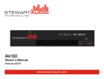
CVA-7400/CVA-7800
Professional Power Amplifier
Owner’s Manual
AMPLIFIERS
Specifications
CVA-7800
FTC Power Rating <.1%THD.
35Hz-20kHz
(both channels driven)
[email protected] volts per channel
Frequency Response
+0dB, -0.5dB
Bandwidth +0dB, -3.0dB
35Hz - 20kHz
35Hz - 20kHz
Signal-to-Noise
(A Weighted, [email protected]? )
Input Impedance
>100dB
20K?
Input Sensitivity ([email protected]? )
1V(0dBV)
Slew Rate
<30V/microsecond
Damping Factor
<200
Input Connectors
3-pin XLRBarrier Strip
Output Connectors
6-Gauge, 5-Way Binding Post
Voltage Gain
40x (32dB)
Power Requirements (1/8 Power)
120C AC 3A
Power Supply Design
High Speed Switching
Dimensions
Weight
Height
Width
Depth
behind front panel
17
1.75 in (4.5cm)
19 in (48.3 cm)
15.3 in (38.9 cm)
14.8 in (37.6 cm)
11 lbs (5kg)
Specifications
CVA-7400
FTC Power Rating <.1%THD.
35Hz-20kHz
(both channels driven)
[email protected] volts per channel
Frequency Response
+0dB, -0.5dB
Bandwidth +0dB, -3.0dB
35Hz - 20kHz
35Hz - 20kHz
Signal-to-Noise
(A Weighted, [email protected]? )
Input Impedance
>100dB
20K?
Input Sensitivity ([email protected]? )
1V(0dBV)
Slew Rate
<30V/microsecond
Damping Factor
<200
Input Connectors
3-pin XLRBarrier Strip
Output Connectors
6-Gauge, 5-Way Binding Post
Voltage Gain
40x (32dB)
Power Requirements (1/8 Power)
120C AC 3A
Power Supply Design
High Speed Switching
Dimensions
Weight
Height
Width
Depth
behind front panel
1.75 in (4.5cm)
19 in (48.3 cm)
15.3 in (38.9 cm)
14.8 in (37.6 cm)
10 lbs (5kg)
Congratulations! You have purchased a powerful product which
will provide you with many years of reliable service. Stewart
Audio’s, committed to innovation in design and quality
workmanship, has provided its customers with a unique
combination of performance and reliability. This philosophy has
attracted the attention a gained the respect of industry professionals
around the world.
The CVA7400 Contractor Series Power Amplifier delivers more
than 200 watts per channel in stereo mode while the CVA-7800
delivers more than 400 watts per channel in stereo mode. Stewart
Audio’s unique power shift correction feature allows the amplifier
to produce crystal clear uncolored sound. This remarkable
performance comes in a package weighing only 10 pounds and 11
pounds while occupying just one standard rack space. Thermal
concerns are minimized in the CVA-7400 and CVA-7800 by
innovative circuitry and extraordinary efficiency, making
installation simpler than ever before.
We at Stewart Audio strive to bring you the finest in
professional electronics, and we thank you for your choice, which
we see as appreciation for our efforts.
Stewart Audio, Inc.
Sonora, CA. 95370
(209) 588-8111 Fax (209) 588-8113
1
16
Contents
Introduction ……………………………………….1
Contents/For the Record ………………………….2
Safety ………………………………………...3 & 4
Special Features ………………………………..5-7
Front Panel Features ……………………………...8
Rear Panel Features ………………………………9
Installation …………………………………..10-13
Trouble Shooting ……………………………14-15
Technical Information ………………………16-17
For The Record
Please fill out and return the enclosed warranty card at
your convenience. This information will provide proof of
ownership for warranty purposes and will allow us to
notify you if necessary.
In the spaces provided below, record the model and
serial number located at the rear of your amplifier.
Model No. ________________________________
Serial No. _________________________________
Purchase Date _____________________________
Retain this information for future reference.
2
Troubleshooting Reference Chart
Symptom:
Recommended Action:
No output: Power indicator LED is off Be sure power outlet is “live”. Be sure
(Note: there is a normal delay of up
power switches are “on”. Check circuit
To 1 minute when amp is first
breaker. Wait 1 minute after plugging
plugged in or circuit breaker is reset.)
in cord or resetting breaker.
___________________________________________________________________
No output: Power indicator LED
This indicates a short-circuit
Cycles on and off.
Condition on the output. Disconnect
speaker wires and turn amplifier
power switch on. If amp stays on, the
problem is in the output wiring or
speakers.
___________________________________________________________________
Power indicator on: no output from
Check input level controls, input and
one or both channels.
Output cables, input signal and
speakers. If operating in bridged mode,
be sure connections are made to
Channel 1’s inputs.
___________________________________________________________________
Low volume in one or both channels.
Check input level controls, input signal
levels, and input wiring. Be sure both
speakers are the same impedance.
___________________________________________________________________
Amplifier overheats and/or shuts off.
Review section on Thermal
Considerations. Note that overdriving
amplifier for a long period can cause
thermal shutdown. Note that
overdriving amplifier hard enough can
cause momentary shutdown.
___________________________________________________________________
Distorted output.
Check signal level and signal source.
Check speaker(s).
___________________________________________________________________
Noise on output.
Check signal source for noise. If you
are running input cables of more than 30
feet, balanced lines can reduce noise
levels considerably. See sections on Input
and Output wiring for more information
on wiring balanced lines.
15
Safety
Troubleshooting
If you experience difficulty in operating your CVA-7400/CVA-7800,
chances are good that you will be able to remedy the problem yourself
using standard troubleshooting techniques and suggestions offered in the
table on the following page.
If you wire your own cable, it is imperative that all connections be made
cleanly with no stray wire strands to short terminals. Keep in mind that
other components in the system can cause problems which may appear to be
caused by the amplifier; systematic troubleshooting will allow you to isolate
the source difficulty.
If you fail to correct the problem by following the steps outlined below, do
not attempt to open or repair the unit yourself. Please contact Stewart
Audio at (209) 588-8111 to obtain a Return Authorization (RA)
Number and shipping instructions. Once RA Number is obtained, return
the unit to Stewart Audio, 14407 Cuesta Court, Sonora, CA. 95370. Do not
return any amplifier to Stewart without first obtaining an RA Number.
Refer to the enclosed Warranty Information for Terms and Conditions of
Warranty.
NOTE: Upon installation of the CVA-7400/CVA-7800, there will be a
turn-on delay of up to one minute after AC power is applied to the
amplifier. This is a result of the initialization sequence preformed by the
amplifier’s High-Frequency Switch Mode Power Supply. Subsequent delays
will be minimal, as long as the CVA-7400/CVA-78001 remains connected to
AC power.
Before using your Stewart Audio Inc. Power Amplifier, please read this
Owner’s Manual carefully to ensure optimum trouble –free performance.
WARNING: TO REDUCE THE RISK OF ELECTRICAL SHOCK,
DO NOT EXPOSE THIS AMPLIFIER TO RAIN OR MOISTURE.
DANGEROUS HIGH VOLTAGES ARE PRESENT INSIDE THE
ENCLOSURE. DO NOT OPEN THE CABINET. REFER
SERVICING TO QUALIFIED PERSONNEL ONLY.
The lighting bolt within arrowhead symbol, within an equilateral
triangle, is intended to alert the user to the presence of uninsulated
“dangerous voltage” within the product’s enclosure that may be
of sufficient magnitude to constitute a risk of electrical shock to
person.
The exclamation point within an equilateral triangle, is intended
to alert the user to the presence of important operating and
maintenance (servicing) instruction in the literature
accompanying the appliance.
Important Safety Instruction – Please Read Prior to Product
Installation.
1. All of the safety and operating instructions should be read before the
amplifier is operated. Retain these instructions for future reference.
All instructions should be followed; all warnings on the amplifier and
in the operating instructions should be adhered to.
2.
14
This amplifier should not be used near water, for example, near a
bathtub, in a wet basement, near a swimming pool, etc.
3. The amplifier should be situated so that it’s location and position does
not interfere with its proper ventilation. For example, the amplifier
must not be placed on a rug, bed, sofa or similar surface that impedes
airflow across the chassis. Airflow through the ventilation openings
should be unobstructed.
3
Wiring Inputs in Parallel
4.
Do not place the amplifier near heat sources such as radiators, heat
registers, stoves, or other appliances that product heat.
5.
The amplifier should be only be connected to 120 VAC, 60 Hz
power supply. Do not defeat the ground or polarization of the power
plug.
6.
Route power cord and other cables so that they are not likely to be
walked on, tripped over or stressed. Pay particular attention to
condition of cords and cables at plugs, and the point where they exit
the amplifier. To prevent risk of fire or injury, damaged cords and
cables should be replaced immediately.
7.
Clean the amplifier with a clean damp cloth. Do not use solvents or
abrasive cleaners. Never pour any liquid on the amplifier.
8.
When left unused for a long period of time, the power cord should be
unplugged form the outlet.
9.
Damaged Amplifiers requiring service. The amplifier should be
serviced by a qualified service technician when:
a.
b.
c.
d.
e.
The power cord or AC plug has been damaged.
Objects have fallen, or liquid has spilled into the unit
The amplifier has been exposed to rain or other moisture
The amplifier does not appear to operate normally or
exhibits a marked change in performance.
The amplifier has been dropped or the enclosure
damaged.
10. The user should not attempt to service the amplifier beyond that
described in the operating instructions. All other servicing should
be referred to qualified service personnel.
4
Wiring XLR and Barrier Strip in parallel (as throughputs to other
equipment) requires special consideration when combining balanced and
unbalanced lines. Connecting an unbalanced lines described above to
any input will render all inputs on that channel unbalanced. If it is
necessary to combine balanced and unbalanced connections on the same
channel, the unbalanced connector must not ground the Negative (-) input.
In the case of the Barrier Strip, this means using the + and - leaving the
ground terminal unconnected. When using the XLR connector(s), pin 3
must be left unconnected (not tied to ground as
described above).
Output Wiring
Outputs are available via both 5-Way Binding Posts. The Binding Posts will
accept bare wire of up to 6 AWG, spade lugs, hook lugs, and a single or
dual banana plugs. When wiring speakers in stereo, red binding post is
connected to the speaker’s positive terminal; black is ground.
Selectable High Pass Filter
The selectable high pass filter for each channel is located on the bottom of
the amplifier. One of the three different frequencies (32Hz, 68Hz, 150Hz at
12dB per octave) may be selected via the white recessed slide switch.
Amplifier Bottom Panel
White selectable High Pass Filter Switch
150Hz 68Hz 32Hz
32Hz 68Hz 150Hz
13
Special Features
Input Wiring
The CVA-7400/CVA-7800’s input sections allow the use of the XLR or
Barrier Strip connectors, and will accept either balanced or unbalanced input
signals.
Pinouts are standard (see diagrams below; Pin 2 of the XLR connector are
“Hot” of Positive.
Input connections should always be made with the amplifier’s power turned
off.
Balanced XLR Connections are made
with the following pin assignments:
#1 = Ground
#2 = Positive (+)
#3 = Negative (-)
The CVA-7400 and CVA-7800 is the result of many years of experience in
the research, development, and manufacturing of amplifiers and other sound
equipment. It is a combination of old and new, cutting-edge electronics and
timeless purity of sound. As such, it represents Stewart Audio’s commitment
to developing the latest available technology to achieve the absolute audio
quality and reliability.
Please take a few minutes to read through this section of the manual, which
provides an overview of the features that make these amplifiers unique.
Low Impedance/High Current Design
The design of the CVA-7400/CVA-7800 is exceedingly conservative with
regard to current capabilities. This ensures that the amplifier’s output devices
remain within their Safe Operating Area, even under extreme conditions. As a
result, the CVA-7400/CVA-7800 runs low impedance loads safely while
retaining the high impact dynamics for which they were designed.
Auto Impedance Optimization
Balanced XLR Connections are made
with the following pin assignments:
#1 = Ground
#2 = Positive (+)
#3 = Ground
12
The High-Frequency Switch Mode Power Supply and amplifier design used in
the CVA-7400/CVA-7800 adapts to the demands placed upon the amplifier,
enabling them to run with maximum efficiency regardless of the load
impedance. Thermal management problems normally associated with
amplifiers of this capacity are therefore greatly reduced. Resources otherwise
applied toward dealing with thermal problems can be put to better use in
higher quality active components for increased reliability and improved
performance.
5
Balanced/Unbalanced Inputs
The CVA-7400/CVA-7800 incorporates XLR and Barrier Strip input
connectors, wired in parallel. This allows throughput of the signal to
additional amplifiers or other equipment such as DAT recorders, etc.
6-Gauge, 5-Way Binding Post and 1/4” Outputs
The CVA-7400/CVA-7800 Binding Posts output connectors will accept
banana plugs, spade lugs, or bare wire up to 6AWG. In addition, the
Binding Posts are positioned to allow one standard banana plug to be used
when operating the amplifier in bridged mode.
In-Rush Current Limiting
A breakthrough from Stewart, the CVA-7400 and CVA-7800 unique inrush
Current limiting circuitry minimizes power drawn from the wall to 8
AMPS or less on plug-in. Staggered turn-on configurations for
multiple-amplifier setups are now a thing of the past, as multiple amplifiers
may be switch on simultaneously.
Selectable High Pass Filter
A selectable high pass filter for each channel (32Hz, 68Hz, 150Hz at 12dB
per octave) has been incorporated for distributed systems.
High-Frequency Switch Mode Power Supply
The CVA-7400 and CVA-7800 features a radical departure from
conventional power supply design: Stewart’s High-Frequency Switch Mode
Power Supply . Because of this pioneering use of advanced technology,
some explanation is in order.
And out the top. In any case, be sure that the sides of the rack (next to the
amplifier) are clear of cables, power strips, etc., so that airflow is
maintained around the heatsink fins.
The amount of airflow is necessary will be determined by a number of
factors, including ambient temperature, the amount of heat generated by
other equipment in the rack, the properties of the rack enclosure being used,
and how hard the amplifier is working. Depending on the installation, it
may be necessary to guarantee airflow around the heatsinks by rearranging
system components or installing a cooling fan in the rack.
Note: To minimize thermal concern, an accessory cooling fan panel
may be installed. Fans may be installed in the front or rear of the rack
in the upper most slots. Fans should be blowing out of the rack. For
further information, please contact Stewart Audio’s customer service.
In a free-standing installation, in which the unit is sitting on a shelf or hard
floors, the rubber feet must be mounted to the bottom of the amplifier.
Under no circumstances should the amplifier be placed directly on carpeting
of a similar surface.
AC Power Considerations
Your Stewart amplifier is designed to operate on 120 volt, 60Hz alternating
current. Power consumption will depend on load impedance, signal level,
and dynamic properties of the program material. At 12.5? per channel,
power draw averages approximately 110 watts.
The CVA-7400/CVA-7800 is equipped with unique inrush current limiting
circuitry which minimizes power drawn from the wall to 8 Amps of less on
power up. Multiple amplifiers may all be switched on at once, without the
need for staggered turn-on configurations.
Conventional supplies operating at 60Hz (standard line frequency)
recharge only 120 times per second, requiring their storage capacitors and
transformer to be quite large to supply the energy needed during the
intervals between cycles when power is not available from the wall. The
power supply must act as a local reservoir of power from which the
amplifier circuits draw. This storage function is responsible for much of the
bulk, weight and cost of traditional power amplifiers.
The Stewart High-Frequency Switch Mode Power Supply fully recharges
120,000 times per second (1000 times faster than conventional supplies),
6
11
Installation
Mechanical Consideration
The Stewart Audio CVA-7400/CVA-7800 occupies one standard rack space
and is only 15” deep and weighs just 10 and 11 pounds respectively,
making it easier to install and transport than almost any other comparable
amplifier. Still, some sensible precautions are in order.
Always use four screws to affix the amplifier to the rack, preferably using
flat washers as well to avoid cosmetic damage to the front panel. When rack
mounting your amplifier it may be necessary to remove the four rubber feet
from the bottom of the unit (in freestanding installations the rubber feet
must be installed). In mobile rack-mounted installations it is recommended
that the rear of the amplifier be stabilized for additional support.
Thermal Considerations
Cooling of the CVA-7400/CVA-7800 is achieved convection, through
heatsinks mounted on each side of the amplifier. In the event that the
chassis temperature reaches 87 degrees C an internal thermostat will open,
turning off the power supply until the amplifier cools down. Although the
CVA-7400/CVA-7800 sophisticated thermal management system makes it
less susceptible to overheating than other amplifiers, it remains necessary to
provide airspace around the chassis. This may mean leaving a rack-space
open above the amplifier. Multiple amplifiers can be racked on top of one
another by leaving a full space between them so sufficient airflow is maintained to allow heat to escape. If mounted in a sealed rack, leave top and
bottom spaces open as well to create a “chimney” effect within the rack,
which will provide cooling as air is drawn in the bottom
10
Requiring far less capacitance for filtering and storage. This high-speed
recharging reduces power supply “sagging” common with other designs. In a
Stewart Amplifier, it is almost as though power is fed directly from the wall to
the speaker with the amplifier acting only as a “valve” in-between to control
its flow. The power supply’s remarkable efficiency at converting energy from
the Ac line to a usable form for loudspeaker applications allows many of the
major components to be downsized , saving space, weight and cost.
Absolute Protection
Stewart Audio power amplifiers employ circuits which fully protect
the amplifier while avoiding sonic compromise. For example, a unique
circuit monitors the current drawn from the power supply. The
amplifier’s output is not affected in any way until the power rating is
exceeded, indicating the presence of a short or overload. Under these
conditions the power supply will simply shut down until the short is
removed, at which point the supply will slowly ramp up to full power,
protecting the load from a surge of energy. In the event of an
amplifier malfunction this circuitry will also protect the speakers,
since the power is immediately disconnected from the amplifier.
Most other amplifier designs require the presence of relatively high
levels of signal in order to detect a shorted output. At low signal
levels, such amplifiers will continue to drive a short, causing rapid
heat buildup, thermal runaway, and finally amplifier failure. The
current-sensing circuitry in all Stewart Contractor Series amplifiers is
capable of detecting a shorted output even at low program levels,
increasing reliability under conditions which could cause other
amplifiers to fail.
7
Front Panel
Sophisticated simplicity is a design objective in the development of all
Stewart Audio amplifiers. These amplifiers remain simple and intuitive to
operate even while incorporating some of the most advanced technology
available today.
Power On/Off and Power Level Indicators
The front panel provides visual feed back of the amplifier’s status via
several LED indicators. The power switch is accompanied by a red LED
which illuminates upon turn.
Note: Upon installation of the CVA-7400/CVA-7800, there will be a turn-on
delay of up to one minute after AC power is applied to the amplifier. This is
a result of the initialization sequence performed by the amplifier’s
High-Frequency Switch Mode Power Supply. Subsequent delays will be
minimal, as long as the CVA-7400/CVA-7800 remains connected to AC
power.
Each channel features two additional LEDs which indicate the level of the
power being produced. Green indicates a signal of –20dB, while Red
indicates that the amplifier is being pushed into clipping. These level indicators are accurate at any load impedance.
Level Controls
A calibrated detented multiple-position input level control has been provided for each channel. These controls are located behind security covers
and are easily accessible on the front panel of the amplifier. . They operate
in conventional fashion (I.e., full clockwise = maximum level.)
Rear Panel
XLR Inputs
Each channel has a female XLR balanced input connector, which may also
be used with unbalanced lines. See Input Wiring in the section on
Installation (page 12) for more details. (Note: the XLR input is wired in
parallel with the Barrier Strip input , so that either may be used as a
“through” connection to feed additional amplifiers or other equipment).
5-Way Binding Post Output Connectors
Each channel incorporates a pair of heavy-duty 5-Way Binding Post output
connectors. They will accept bare wire, spade lugs, hook lugs, and single or
dual banana plugs. Additionally the binding posts are situated so that when
the amplifier is configured for bridged operation, one dual banana plug may
be inserted across the terminals. See Output Wiring in the section on
Installation (page 13) for more details.
Remote Turn on Feature
When using the CVA-7400/CVA-7800 with a Controller or other
preamplifier with a remote trigger outlet, the amplifier can be turned on
remotely. This unique circuit will allow several amplifiers to be connected
directly to the AC Power Strip. The Remote Turn On input may be
Activated by any five volt signal source.
Removable AC Line Cord
For convenience during the installation, Stewart has included a removable
AC power cord. Please make sure that this cord is connected to a grounded
20 amp un-switched AC outlet.
8
9


