1
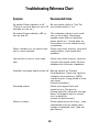
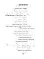
DA-70 Series
Professional Power
Amplifiers
Owners Manual
Safety
Before using your Stewart Audio Power Amplifier,
please read this owner’s manual carefully to
ensure optimum trouble-free performance.
Warning: To REDUCE THE RISK OF ELECTRICAL SHOCK,
DO NOT EXPOSE THIS AMPLIFIER TO RAIN OR MOISTURE.
DANGEROUS HIGH VOLTAGES ARE PRESENT INSIDE THE
CHASSIS. DO NOT OPEN THE COVER. REFER SERVICING
TO QUALIFIED PERSONNEL ONLY.
CAUTION
RISK OF ELECTRICAL SHOCK
DO NOT OPEN
CAUTION: TO REDUCE THE RISK OF ELECTRICAL SHOCK, DO NOT
REMOVE COVER (OR BACK). NO USER-SERVICABLE PARTS INSIDE.
REFER SERVICING TO QUALIFIED SERVICE PERSONENEL.
The lightning flash with arrowhead symbol, within an equilateral
triangle, is intended to alert the user to the presence of uninsulated
“dangerous voltage” within the product’s enclosure that may be of
sufficient magnitude to constitute a risk of electrical shock to persons.
The exclamation point, within an equilateral triangle, is intended to
alert the user to the presence of important maintenance (servicing)
instructions in the literature accompanying the appliance.
1
- Important Safety Instructions Please Read Prior to Product Installation.
All of the safety and operating instructions should be read before the amplifier is operated. Retain these instructions for future reference. All instructions should be followed; all warnings
on the amplifier and in the operating instructions should be adhered to.
This amplifier should not be used near water, for example,
near a bath tub, washbowl, kitchen sink, laundry tub, in a wet
basement, near a swimming pool, etc
The amplifier should be situated so that its location and position do not interfere with its proper ventilation. For example,
the amplifier should not be placed on a rug, sofa, or similar
surface which impedes the airflow across the chassis. Airflow
through the ventilation openings should be unobstructed.
The amplifier should only be connected to a properly grounded
AC outlet as indicated under AC Power Connections in this
manual. Do not defeat the ground or polarization of the power
plug.
Route all power cords and other cables so that they are not
likely to be walked on, tripped over, or stressed. Pay particular
attention to condition of cords and cables at plugs, and the
point where they exit from the amplifier. To prevent risk of fire
or injury, damaged cords and cables should be replaced immediately.
Clean the amplifier with a damp cloth. Do not use solvents or
abrasive cleaners. Never pour any liquid on or in the amplifier.
The amplifier should only be serviced by qualified service personnel.
2
Introduction:
Congratulations! You have just purchased a new, state of the
art, Digital Power Amplifier which will provide you with many
years of reliable service. Stewart Audio’s commitment to
innovation in design and quality workmanship has provided its
customers with a unique combination of performance and
reliability. This commitment to excellence has gained the
respect of industry professionals around the world.
The DA-70 Series Professional Series Power Amplifier utilizes a
new high speed switching power supply and Damped Ternary
Modulation Digital output topology. The amplifier will deliver
over 70 Watts of power per channel and may be purchased in
either a 2 or 4 channel configuration. This remarkable
performance comes in a very compact package weighing a
mere 3.4 pounds and occupying just one-half standard rack
space. The DA-70 Series Amplifiers are convection cooled and
require no noisy fans for cooling.
We at Stewart Audio strive to bring you the finest in
professional electronics, and we thank you for your choice,
which we see as an appreciation for our efforts.
The Stewart Audio Design Team
3
Contents
Special Features……………………………………………….……...…6
Front Panel Features……………………………..…………….…...10
Rear panel Features …………………………………………….…… 11
Installation……………………………………………………………...….12
Troubleshooting………………………………………………………....15
Technical Information………………………………………………...17
For The Record
In the spaces below, record the Model, Serial number
and Purchase information of your Power Amplifier.
Model Number: ____________
Serial Number: ____________
Purchase Date: ____________
Purchased From: ___________
Retain this information for future reference.
4
Special Features
Stewart Audio’s new “Compact Series” Power Amplifiers utilizes the latest in Digital Audio Technology. The new, all Digital DA Series Power Amplifiers were developed by Stewart Audio’s Digital Audio Team and represent the pinnacle of Stewart Audio technology
and design.
Please take a few moments to read through this section of the manual, which provides
an overview of the features that makes this amplifier unique.
How is the DA-70 Amplifier different from other Amplifiers?
The primary difference between the DA-70 Series and other
amplifiers is that it is all digital and it has much higher efficiency. Current digital audio systems use Class A/B amplifiers
to amplify analog signals produced by a DAC. Analog designs
have low efficiencies because of the power consumed in the
active components as a result of the voltage difference between the amplifier's output and it's power supply. This continuous control of the supply voltage results in peak efficiencies of about 50%. As a result a large power supply and heat
sink are required.
Class D switching amplifiers were developed to overcome this
problem by discretely connecting the load to the power supply.
Higher efficiency is achieved, but Class D is still essentially an
analog solution because it utilizes an analog interface and control. Stewart’s approach was to develop a new Class D amplifier that utilized digital control. This approach enables lower
cost through digital integration, as well as, eliminating performance degradation due to analog component variations.
5
What is Damped Ternary Modulation?
Conventional Class D amplifiers utilize binary, or BI-state operation. Binary consists of only two switching states, positive power and negative
power. Ternary, or tri-state operation, consists of three switching states;
positive, negative and a zero power state. The third state is unique to this
design. During the time when neither supply connection is required, both
speaker terminals are connected to each other providing damping to the
loudspeaker, hence the name damped ternary. The figure below shows the
advantage of the damped ternary compared to binary modulation for a
sine wave. In binary the cancellation of two full level signals is required for
small outputs. Thus, the amplifier is continuously providing full output!
This represents wasted power. It also produces unwanted RF energy that
must be kept from radiating. In contrast, the damped ternary design only
supplies power to produce a signal.
Damped Ternary Advantage over Binary
In tests using the same hardware configured for ternary and then for binary, ternary's high frequency energy at zero output is attenuated over 20
dB below binary operating into the same filter! This means higher efficiency and smaller filter components.
6
What is the efficiency advantage of the DA-70 Series over other
amplifier designs?
As shown in the figure below, the ternary design has a 20% advantage
over binary Class D at music levels (typically 15% of full scale) and about
3 times the efficiency of analog
amplifiers!
The Power Supply
The foundation of all amplifier design is the power supply. For years
Stewart Audio has pioneered leading edge, power supply technology. All
Stewart Audio amplifiers feature a High-Frequency Switch Mode Power
Supply. Because of this use of advanced technology some explanation is
in order.
Conventional Power Supplies operating at 60Hz (standard line frequency)
recharge only 120 times per second, requiring their storage capacitors
and transformers to be quite large to supply the energy needed during
the intervals between cycles
7
when power is not available from the wall. The power supply must act as
a local reservoir of power from which the amplifier circuits draw. This
storage function is responsible for much of the bulk, weight and cost of
traditional power
amplifiers.
High Frequency Switch Mode Power Supplies
Stewart’s famous, High Frequency Switch Mode Power Supplies fully recharges 1000 times faster than conventional supplies, requiring far less
capacitance for filtering and storage. This high-speed recharging reduces
power supply “sagging” common with other designs.
The New DA-70 Series Digital Amplifiers utilizes a new, regulated,
forward converter design Switch Mode Power Supply operating at a frequency 2/3 faster than our old standard supply.
Power Factor Correction
Models with a PFC designation utilizes Power Factor Correction circuitry in
their power supply. This circuitry automatically adjusts the power supply
to provide stable, full output over a wide range of mains voltages, typically from 90VAC to 240VAC. This feature makes the DA-70 Series operable anywhere in the world, and is a very useful feature when
operating from unstable or questionable AC mains.
This power supply’s remarkable conversion efficiency combined with
Damped Ternary Modulation translates into major savings of energy
drawn from the AC line. The benefits are reduced heat dissipation, and
downsizing of most major components. This saves space and weight
without sacrificing the Sonic excellence Stewart Audio is famous for.
Bridging
Bridging of the DA-70 Series is not possible due to the high
efficiency design of the Damped Ternary Modulation.
8
Balanced / Unbalanced Inputs
All DA–70 Series amplifiers feature Phoenix Type input Connectors, which
will accept either balanced or unbalanced signals.
See Input Wiring in the section on Installation (Page 13) for more details.
Output Connections
All DA–70 Series amplifiers feature Phoenix Type output Connectors, one
for each channel. NOTE: Do not attempt to Bridge this amplifier or tie the
commons together. Serious damage to your amplifier may occur if this is
attempted.
Total Protection
The DA-70 Series amplifiers employ circuitry which fully protect the amplifier while avoiding sonic compromise.
Front Panel
Simplicity is a design objective in the development of all Stewart Audio
power amplifiers. These amplifiers remain simple and intuitive to operate
even while incorporating some of the most advanced technology available
today.
Power On/Off and LED Clip Indicators
The front panel provides visual feedback of the amplifiers status. The front
panel power switch is accompanied by an LED which will illuminate upon
power-up. (Note there is an initial delay of up to 30 seconds when the amplifier is first turned on.) Additional LEDs (one for each channel) will illuminate when the amplifier is being pushed into clipping.
Level Controls
The DA-70 Series has been equipped with a level control for each channel,
conveniently located on the front panel. With typical program level present,
adjust each channel to provide the desired output level. If undesirable distortion is present, check preceding components and make necessary adjustments.
9
Rear Panel
Inputs
Each Channel has a phoenix type connector which may be used with either balanced or unbalanced lines.
See Input Wiring in the section on Installation (Page 13) for more details.
Speaker Outputs
Each Channel has a phoenix type connector which may be used to connect loudspeakers.
See Output Wiring in the section on Installation (Page 13) for more details.
AC Power Connection
All DA-70 Series amplifiers are equipped with a IEC socket on the rear
apron for AC connections.
Models DA-70-2 and DA-70-4 may only be connected to 120VAC mains.
Models DA-70-2-PFC and DA-70-4-PFC are Power Factor Corrected and
may be connected to any AC main voltage from 90VAC-240VAC.
10
Installation
Mechanical considerations
The Stewart Audio DA-70 Series amplifier occupies just one-half standard
rack space, is only 10.6” deep and weighs just over 3 pounds, making it
easier to install and transport than almost any other comparable power
amplifier. Still some precautions are in order.
Rack mounting of the DA-70 Series may be achieved by using either the
Stewart Audio RMK-70-S or RMK-70-D rack kits. The RMK-70-S centers the
amplifier in a single rack space, while the RMK-70-D allows you to rack two
amps side by side in a single rack space. For stability always use four screws
to affix the amplifier to the rack, preferably using rack washers to avoid
cosmetic damage to the rack mount panels. When rack mounting your
DA-70 Series amplifiers be sure to remove the four adhesive rubber feet
from the bottom of the unit. The DA-70 Series amplifiers can also be
mounted to a standard rack shelf or used as a stand alone product.
Thermal Considerations
Cooling of the DA-70 Series amplifiers is achieved by Stewart’s unique whole
chassis heatsink design, which utilizes the entire chassis as a heatsink to
cool the heat generating components inside. In the event the internal
ambient temperature reaches 85 degrees centigrade, the protection circuit
will shut down the power supply until the amplifier cools down.
Although the sophisticated thermal management system in the DA-70 Series
makes it less susceptible to overheating than other amplifiers, it remains
good practice to provide airspace around the chassis.
NOTE: A –4 model (4 channel) amplifier will dissipate twice the heat of a
–2 model (2 channel) amplifier and a PFC model will dissipate approximately
10% more heat than a non PFC model Therefore while a DA-70-2 runs very
cool, the DA-70-4-PFC will require a little more attention to cooling.
Multiple amplifiers can be racked on top of one another without leaving a full
rack space between them as long as sufficient airflow is maintained to allow
heat to escape out the top.
11
If mounted in a sealed rack, leave the top and bottom spaces open to create a
chimney effect within the rack, which will provide cooling as air is drawn in the
bottom and exhausted
out the top. The amount of airflow necessary will be determined by a number of
factors, including ambient temperature, the amount of heat generated by other
equipment in the rack, the properties of the enclosure being used, and how hard
the amplifier is working. In extreme cases it might be necessary to install a
cooling fan in the rack for additional cooling.
In free standing installations where the amplifier is sitting on a shelf or hard
floor the four rubber feet must remain mounted to the bottom of the amplifier.
Under no circumstances should the amplifier be placed directly on carpeting or
similar surfaces.
AC Power Considerations
Your Stewart Audio DA-70-2 and DA-70-4 amplifiers are designed to operate on
120 volt, 60 Hz AC current.
Your Stewart Audio DA-70-2-PFC and DA-70-4-PFC amplifiers are designed to
operate over a range of 90 volts - 240 volts, 50-60 Hz alternating current.
Average power consumption will depend on load impedance, signal level and
program material.
Typical power consumption in Amperes:
(All channels driven @ 4 Ohms /120V AC)
Model
DA-70-2
DA-70-4
DA-70-2-PFC
DA-70-4-PFC
Idle 1/8 power
0.2
0.4
0.3
0.7
0.2
0.4
0.3
0.8
1/3 Power
0.6
1.3
0.7
1.4
12
Full Power
1.4
3.0
1.6
3.2
Input Wiring
Your DA-70 Series amplifier is provided with a 3 conductor Phoenix Type
connector for each input.
The connector may be wired Balanced by connecting to Signal ground,
Signal – and Signal + as marked on the chassis over each input. If you
wish to operate the amplifier unbalanced, connect your unbalanced line
across Signal ground and Signal + and add a jumper from Signal – to
Signal ground.
Output (Speaker) Wiring
Your DA-70 Series amplifier is provided with a two conductor Phoenix Type
connector for each output.
The connector may be wired by connecting the speaker line to – and + as
marked on the chassis over each output.
Caution: Due to the ternary design of the output stage Bridging of
this product line is not possible.
Do not tie any output pin to any other pin or to ground. Never connect any speaker terminal to anything other than a single output
pin.
WARNING:
Violation of this Caution may result in damage to your amplifier
and will void your Stewart Audio Warranty.
13
Trouble shooting
If you experience difficulty in operating your new DA-70 Series amplifier, Chances are good that you will be able to remedy the problem yourself using standard troubleshooting
techniques and the suggestions offered in the troubleshooting table on the next page.
When wiring cables it is imperative that all connections be
made cleanly with no stray wire strands to short terminals.
Make sure the wire clamp screws are tight. For proper connection all wire should be stripped to bare approximately ¼
inch of wire. Make sure that the connector set screw seats on
copper, not insulation.
Keep in mind that other components in the system can cause
problems which may appear to be caused by the amplifier;
systematic troubleshooting will allow you to isolate the
source of difficulty.
If you fail to correct the problem by following the outlined
chart on the next page, do not attempt to open or repair
the unit yourself.
Please contact Stewart Audio at 209.588.8111 to obtain a Return Authorization (RA) Number and shipping
instructions. Once an RA Number is obtained, return the
unit to Stewart Audio at the address indicated on the RA
Form. Refer to the enclosed Warranty information for Terms
and Conditions of Warranty.
14
Troubleshooting Reference Chart
Symptom:
Recommended Action:
No output Power indicator is off.
Be sure power outlet is “live” Be
(There is a normal delay of up to 30 sure power switch is “on.”
seconds on turn-on.)
No output Power indicator LED cycles on and off.
This indicates a short-circuit condition on the output. Disconnect
speaker wires and turn amplifier
power switch on. If amp stays on,
the problem is in the output wiring
or speakers.
Power indicator on; no output from
one or more channels.
Check input level controls, input and
output cables, input signal and
speakers.
Low volume in one or more channels.
Check input level controls, input wiring and input signal levels. Be sure
speakers are the same impedance.
Amplifier overheats and/or shuts off. Review section on Thermal
Considerations. Check clip lights for
indication of overdriving. (NOTE:
overdriving for a long period of time
can cause
thermal shutdown.)
Distorted output.
Check input signal level and
signal source. (Set gain by
turning amplifier volume all the way
down, set preamp level to normal,
turn up amplifier
volume to desired level.)
Noise on output.
Check signal source for noise. Long
unbalanced lines can cause noise,
change to balanced lines. (See set
gain above.)
15
Specifications
8 Ohm Stereo Power 35 Watts/Ch
4 Ohm Stereo Power 70 Watts/Ch
Frequency Response (+0, –0.5 dB, 20 Hz—20 kHz
1W)
Full Power Bandwidth (20-Hz-20 kHz) ± .7 dB
Signal to Noise >93 dB
THD+N < .25%
Input Sensitivity 1V (0 dBV)
Standard Voltage Gain 17X (25 dB)
Input impedance (Balanced / Unbal- 20k Ohms / 5k Ohms
anced)
Class Damped Ternary Modulation
Input Connectors Phoenix Type
Output Connectors Phoenix Type
Power Supply High Speed Switching
Cooling Convection (No Fans)
Controls Power on/off, Channel Gain
LED Indicators Power & Clip
Construction Steel & Aluminum Chassis
Dimensions (height, width, depth) 1.75”H x 8.26”W x 10.6”D
Max Weight 3.4 lbs (1.54 kg)
Warranty 3 years Parts & Labor
16
Notes:
Stewart Audio
1000 Technology Drive
Columbia, Ca 95310
Tel: 209.588.8111 Fax: 209.588.8113
www.Stewartaudio.com