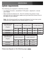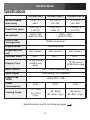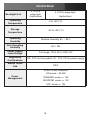
1
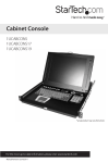
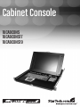
Cabinet Console
1UCABCONS
1UCABCONS17
1UCABCONS19
FCC Compliance Statement
This equipment has been tested and found to comply with the limits for a Class B digital
device, pursuant to part 15 of the FCC Rules. These limits are designed to provide reasonable
protection against harmful interference in a residential installation. This equipment generates,
uses and can radiate radio frequency energy and, if not installed and used in accordance with
the instructions, may cause harmful interference to radio communications. However, there is
no guarantee that interference will not occur in a particular installation. If this equipment does
cause harmful interference to radio or television reception, which can be determined by turning the equipment off and on, the user is encouraged to try to correct the interference by one
or more of the following measures:
• Reorient or relocate the receiving antenna.
• Increase the separation between the equipment and receiver.
• Connect the equipment into an outlet on a circuit different from that to which the receiver
is connected.
• Consult the dealer or an experienced radio/TV technician for help.
Use of Trademarks, Registered Trademarks, and other Protected Names and Symbols
This manual may make reference to trademarks, registered trademarks, and other protected
names and/or symbols of third-party companies not related in any way to StarTech.com.
Where they occur these references are for illustrative purposes only and do not represent an
endorsement of a product or service by StarTech.com, or an endorsement of the product(s)
to which this manual applies by the third-party company in question. Regardless of any direct
acknowledgement elsewhere in the body of this document, StarTech.com hereby acknowledges that all trademarks, registered trademarks, service marks, and other protected names
and/or symbols contained in this manual and related documents are the property of their
respective holders.
Instruction Manual
Table of Contents
Introduction ................................................................................... 1
System requirements..................................................................... 2
Assembly......................................................................................... 5
Installation....................................................................................... 10
Connecting to a USB Controlled Computer..................................10
Connecting to a PS2 Controlled Computer..................................11
Connecting to a KVM Switch........................................................11
Operation......................................................................................... 12
Front Panel Functions...................................................................12
Keyboard Replacement.................................................................. 13
Touchpad Replacement................................................................. 14
Specifications................................................................................. 15
Technical Support.......................................................................... 17
Warranty Information..................................................................... 17
Screen Quality & Pixel Policy.......................................................17
i
Instruction Manual
Introduction
Thank you for purchasing a StarTech.com 1U Cabinet Console. This
console offers the ultimate in computer management, especially for
applications where space is at a premium.
The console drawer can be pulled out from the rack for operation, on
sliding rails that latch in the extended position; when not in use, the
Active Matrix TFT display can be folded down, locked, and secured while
pushed in. With different rear bracket & extension kits, the console can
be mounted on rack cabinets of various depths.
Features
• 1UCABCONS: Flip-open 15” TFT LCD panel supports
1024 x 768 @60/70/75
1UCABCONS17: Flip-open 17” TFT LCD panel supports
1280 x 1024 @60/70/75
1UCABCONS19: Flip-open 19” TFT LCD panel supports
1280 x 1024 @60/70/75
• Standard 19” 1U rack drawer
• Modular design
• Full 105 key, low-profile, sturdy keyboard built-in
• Standard connectors for PC connection
• Supports replaceable keyboard, mouse and module selection
• Locking mechanism locks the drawer when pulled out, pushed in or
folded down
• For rack cabinets with depth from 20” (50cm) and up (with appropriate
rear bracket and extension kit)
• Quick and easy installation
• Optional KMV switches available
1
Instruction Manual
System requirements
The following are required to install the console:
• 1U Cabinet Console - assembled “LCD panel + keyboard + mouse
pad” drawer
• Rear bracket & extension kit - This kit contains two pieces of rear
brackets and two extensions. Make sure you have the correct kit to fit
the depth of your cabinet.
Note: the following length is measured between front and rear poles,
inside the rack cabinet not the outside depth of a rack
Front pole to rear
pole distance
1UCABCONS
1UCABCONS17
1UCABCONS19
( Depth )
cm
inch
cm
inch
Minimum
59
23.2
59
Maximum
96
37.8
96
Front pole to rear
pole distance
cm
inch
23.2
59
23.2
37.8
123
48.4
CABCONS30KIT
CABCONS42KIT
cm
inch
cm
inch
Minimum
57.5
22 5/8
77.5
30 1/2
Maximum
70.5
27 3/4
90.5
35 5/8
( Depth )
Please see diagram on the following page
2
Instruction Manual
Overhead Diagram
KVM Module
Console
Drawer
Console
Drawer
Depth
Depth
KVM Module
The KVM Module can be connected to a console, or be used as a standalone KVM Switch. There are three major categories: PS/2, USB and
Sun Interfaces:
Type
PS/2 KVM
Model name
CAB832DS
CAB1631D
CAB1631D1U
No. of Console Ports
2
1
1
No. of Computer Ports
8
16
16
OSD Menu
Yes
Yes
Yes
Height
1U
2U
1U
Cable Type
SVPS23N1_xx
PS23N1THINxx
SVECONxx
Continued next page
3
Instruction Manual
Type
Model name
Hybrid KVM
CAB831HD
Interface
CAB1631HD
PS/2, USB
No. of Console Ports
1
1
No. of Computer
Ports
8
16
OSD Menu
Height
Yes
1U
Cable Type
2U
PS2 – SVECONx
USB - SVECONUSx
Type
IP KVM
Model name
CAB1641HDI
Interface
PS/2, USB
No. of Console Ports
1
No. of Computer
Ports
16
OSD Menu
Yes
Height
1U
PS2 – SVECONx
Cable Type
USB - SVECONUSx
4
Instruction Manual
Assembly
1.Choose a proper position for the rack drawer. Mount the rear brackets
(from the Rear bracket & extension kit) and lightly fasten them onto the
rear vertical poles. Both will be removed later.
2.Remove the safety stopper from the console drawer. The safety
stopper is designed to prevent the drawer from sliding out during
transportation. Please note that once the Safety Stopper is removed,
the drawer is free to slide out when the console is tilted. Be cautious,
as this could cause injury.
5
Instruction Manual
3.Slide the assembled drawer into the rack cabinet from the front and
insert the two slide rails of the assembled drawer into the pockets of
the rear brackets.
4.Fasten the assembled drawer onto the front brackets using the four
screws provided.
5.Remove both of the rear brackets. The front brackets now hold the
assembled drawer.
6
Instruction Manual
6.Attach the extensions (from the Rear bracket & extension kit) to both
sides of the KVM switch module. Please note the length of the
extensions and mount them as shown. For a 2U module, the
extensions are mounted to the lower half of the module.
NOTE: the orientation of the wide side of the extension
7.The rear brackets, extensions and slide rails have a tight fit. Make sure
you follow these steps for easy installation.
A.Slide the rear brackets onto the extensions.
B. Insert both sliding rails of the assembled drawer into the tight space
formed by the rear brackets and the extensions. The KVM module
should be pushed in evenly on both right and left sides.
7
Instruction Manual
8.Push the KVM switch module evenly toward the drawer:
9.Slide the console drawer out and fasten both units together using the
screws provided:
8
Instruction Manual
10. Make sure the C-36 connectors are firmly connected:
8mm (5/16”)
C36 Connector
11.Connect the power supply to the power jack on the KVM module to
complete the assembly.
9
Instruction Manual
Installation
Please note: You can only connect to a computer using either the PS/2
or USB port not both simultaneously.
Connecting to a USB Controlled Computer
Connect the standard VGA cable and a USB A-B cable to the computer
and 1UCABCONS as shown below. The computer can be a USB-ready
PC, Sun, HP server, or a Mac.
Male-to-Female
HDB15 for VGA
10
Instruction Manual
Connecting to a PS2 Controlled Computer
Connect the standard VGA cable and two mini-DIN6 male-to-male cables
to the computer and 1UCABCONS as shown below. There are two miniDIN6 female connectors marked with keyboard and mouse, be sure not to
swap the connections.
Male-to-Female
HDB15 for VGA
Connecting to a KVM Switch
When cascading with a KVM switch, 1UCABCONS can be used to control
up to 16 computers. The connection is exactly the same as is shown
above (see Connecting to a USB Controlled Computer, or Connecting to
a PS/2 Controlled Computer). The only difference is the connection would
be made to the “CONSOLE PORT” (could be “PS/2” or “USB” interface) of
the KVM switch instead, of a computer.
Please choose either PS/2 or USB to connect, prior to turning on
your computer!
11
Instruction Manual
Operation
Front Panel Functions
1
2
3
4
10
5
6
7
8
9
KVM Control and Status:
(This section is effective only when a KVM switch module is connected.)
1.Computer Selection Pad - Press one of these pushbuttons to select a
computer. For 16 port models, 1-8 represent the lower 8 ports, while
A-H indicates the higher 8 ports. Port 1 and A share the same push
button; if port 1 is already selected, tap its pushbutton to select port A.
If port 1 is not selected, press and hold pushbutton 1 for two seconds
to select port A.
2.Selected Computer Indicator - One of the indicators turns red when
a corresponding computer is selected by pushbuttons, hotkey or OSD
menu.
3.Local Console in Operation - When a computer is accessed through
the console, this will illuminate green.
4.Remote Console in Operation - This will illuminate green when a
computer is accessed by another set of keyboard/mouse/monitor
connected to the Remote console when the KVM Switch Function
Module is a 2-console KVM.
LCD Panel Control:
5.LCD Panel Menu - These buttons invoke the OSD menu for the LCD
panel and acts as menu selection.
6.LCD Panel Adjustment - Lets you adjust settings for the LCD panel.
12
Instruction Manual
Keyboard Status and LCD Panel Power Switch:
7.Num Lock - Keyboard Num Lock status
8.Caps Lock - Keyboard Caps Lock status
9.Scroll Lock - Keyboard Scroll Lock status
10. LCD Panel Power Switch
Keyboard Replacement
The keyboard is replaceable, in the event of language changes or
maintenance. To replace the key-board, tilt it up, locate the mini-USB
cable underneath the keyboard and unplug it gently. While installing the
replacement keyboard, please ensure that you extend just enough of the
cable to keep the keyboard flat inside the tray.
Triangular Mark
Please note: There is a round hole under the drawer, which can be used
to pass one finger through allowing for easier removal of the keyboard
(pushing upwards).
Please note: The triangular mark on the mini USB connector must face
outwards.
13
Instruction Manual
Touchpad Replacement
The built-on Touchpad offers “wheel mouse” functionality. The area of
the Touch Pad to the right side of the two small triangular marks is the
simulated “wheel” as shown below:
Triangular Marker
Scroll
Wheel
Area
Left Mouse Button Right Mouse Button
To remove the Touch Pad, press the tab underneath it upward to release
the latch, then slide it outwards until the Touch Pad can be lifted up clear
from the notches, as shown in the figure below (right side). The Touchpad
is attached by a piece of mini-USB cable. To install the Touchad, extend
just enough mini-USB cable and slide the Touch Pad all the way in till you
hear a click sound as it is locked in position.
Triangular Mark**
**Please note that the triangular mark must face outward
14
Instruction Manual
Specifications
Active Display
Area (mm)
Pixel Pitch (mm)
Resolution
1UCABCONS
1UCABCONS17
1UCABCONS19
304.1 x
337.920 x
270.336
376.32 x
228.1
0.297(H) x
0.297(V)
0.264 (H) x
0.264 (V)
0.294(H) x
0.294(V)
1024 x 768
@60/70/75Hz
1280 x 1024
@60/70/75Hz
Color Pixel
Arrangement
RGB vertical strip
Display Mode
Normally White
Brightness(cd/
m2)
301.056
250 (center)
260 (center)
250 (center)
Contrast Ratio
350:1
400:1
500:1
Display Color
16.2M colors
(RGB 6-bits
data)
16.7M colors
(RGB 8-bits data
User Control
OSD Control (auto saving)
Input Signal
RGB analog, H/V separate
Plug-n-Play
VESA
VESA DDC 1/2B
Power
Consumption
33W
37W
-70~70(H)
Viewing Angle
-60~60(V)
(Typ.)
-80~80(H)
-85~85(H)
-80~80(V) (Typ.)
-85~85(V) (Typ.)
Specifications cont’d on following page
15
40W
Instruction Manual
Backlight Unit
2 CCFLs
edge-light
(top/bottom)
4 CCFLs edge-light
(top/bottom)
Operating
Temperature
0 to +50 (°C)
Storage
Temperature
-20 to +60 (°C)
Operating
Humidity
Relative Humidity 8% ~ 95%
Non-Operating
Humidity
95% RH
Power Supply
Input Voltage
Full range, 100V AC to 240V AC
Regulatory
Certifications
CE, FCC for the product. UL, TUV, CE for power supply
Mouse Touch
Pad
PS/2
VESA DPMS compliant
Power
Management
ON mode = 23.2W
STANDBY mode <= 1W
SUSPEND mode <= 1W
OFF mode <= 1W
16
Instruction Manual
Technical Support
StarTech.com’s lifetime technical support is an integral part of our commit-ment to provide industryleading solutions. If you ever need help with your product, visit www.startech.com/support and access our
comprehensive selection of online tools, documentation, and downloads.
Warranty Information
This product is backed by a one year warranty.
In addition, StarTech.com warrants its products against defects in materials and workmanship for the periods
noted, following the initial date of purchase. During this period, the products may be returned for repair,
or replacement with equivalent products at our discretion. The warranty covers parts and labor costs only.
StarTech.com does not warrant its products from defects or damages arising from misuse, abuse, alteration,
or normal wear and tear.
Limitation of Liability
In no event shall the liability of StarTech.com Ltd. and StarTech.com USA LLP (or their officers, directors,
employees or agents) for any damages (whether direct or indirect, special, punitive, incidental, consequential,
or otherwise), loss of profits, loss of business, or any pecuniary loss, arising out of or related to the use of the
product exceed the actual price paid for the product. Some states do not allow the exclusion or limitation
of incidental or consequential damages. If such laws apply, the limitations or exclusions contained in this
statement may not apply to you.
Screen Quality & Pixel Policy
During the manufacturing process, certain cosmetic imperfections can occur which do not constitute defects
in the screen requiring an RMA replacement. Defective or “dead” pixels or sub-pixels are common to all
manufacturers of LCD displays. Visual imperfections are caused by one or more defective pixels or subpixels.
A pixel is comprised of one red, one green, and one blue sub-pixel. If a defective whole pixel is always on,
it will appear as a bright spot, typically white, yellow or other bright color, while if it is always off, it will
appear as a dark brown of black spot visible on a bright background. A defective sub-pixel is less visible than
a defective whole pixel as it is smaller, and dependent on the color of the defective sub-pixel as contrasted
to the background color.
A display is not deemed defective if it contains less than and up to:
• 3 bright dots (pixel always on)
• 5 dark dots (pixel always off)
• 5 total bright and dark dots (on and off pixels)
If your display appears to have defective pixels or sub-pixels, or if you should have any questions relating to
this policy, please contact StarTech.com technical support either by phone, online live chat, or email.
17
StarTech.com has been making “hard-to-find easy” since 1985,
providing high quality solutions to a diverse IT and A/V customer
base that spans many channels, including government, education
and industrial facilities to name just a few. We offer an unmatched
selection of computer parts, cables, A/V products, KVM and Server
Management solutions, serving a worldwide market through our
locations in the United States, Canada, the United Kingdom and
Taiwan.
Visit www.startech.com today for complete information about
all our products and to access exclusive interactive tools such as
the Cable Finder, Parts Finder and the KVM Reference Guide.
StarTech.com makes it easy to complete almost any IT or A/V
solution. Find out for yourself why our products lead the industry
in performance, support, and value.