1
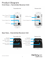
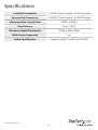
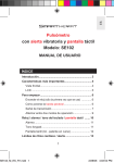
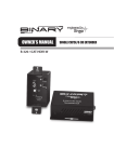
Wall Plate HDMI® over Cat 5e/6
Extender - 165ft (50m)
ST121HDWP
*actual product may vary from photos
DE: Bedienungsanleitung - de.startech.com
FR: Guide de l'utilisateur - fr.startech.com
ES: Guía del usuario - es.startech.com
IT: Guida per l'uso - it.startech.com
NL: Gebruiksaanwijzing - nl.startech.com
PT: Guia do usuário - pt.startech.com
For the most up-to-date information, please visit: www.startech.com
Manual Revision: 05/07/2015
FCC Compliance Statement
This equipment has been tested and found to comply with the limits for a Class B digital
device, pursuant to part 15 of the FCC Rules. These limits are designed to provide reasonable
protection against harmful interference in a residential installation. This equipment generates,
uses and can radiate radio frequency energy and, if not installed and used in accordance with
the instructions, may cause harmful interference to radio communications. However, there
is no guarantee that interference will not occur in a particular installation. If this equipment
does cause harmful interference to radio or television reception, which can be determined by
turning the equipment off and on, the user is encouraged to try to correct the interference by
one or more of the following measures:
• Reorient or relocate the receiving antenna.
• Increase the separation between the equipment and receiver.
• Connect the equipment into an outlet on a circuit different from that to which the receiver
is connected.
• Consult the dealer or an experienced radio/TV technician for help.
Use of Trademarks, Registered Trademarks, and other Protected Names and Symbols
This manual may make reference to trademarks, registered trademarks, and other
protected names and/or symbols of third-party companies not related in any way to
StarTech.com. Where they occur these references are for illustrative purposes only and do not
represent an endorsement of a product or service by StarTech.com, or an endorsement of the
product(s) to which this manual applies by the third-party company in question. Regardless
of any direct acknowledgement elsewhere in the body of this document, StarTech.com hereby
acknowledges that all trademarks, registered trademarks, service marks, and other protected
names and/or symbols contained in this manual and related documents are the property of
their respective holders.
Instruction Manual
Table of Contents
Product Diagram.....................................................................................1
Front View – Transmitter/Receiver Unit.............................................................................................. 1
Rear View – Transmitter/Receiver Unit............................................................................................... 1
Introduction.............................................................................................2
Packaging Contents.................................................................................................................................. 2
System Requirements............................................................................................................................... 2
Preparing Your Site.................................................................................2
Hardware Installation.............................................................................3
EDID Configuration.................................................................................4
Automatic EDID Configuration............................................................................................................. 4
Manual EDID Configuration (EDID Copy / EDID Ghost)................................................................ 4
Restore EDID to Factory Default Settings.......................................................................................... 5
LED Indicator...........................................................................................5
Specifications...........................................................................................6
Technical Support...................................................................................7
Warranty Information.............................................................................7
Instruction Manual
i
Product Diagram
Front View – Transmitter/Receiver Unit
Transmitter Unit
Receiver Unit
Status (Power) LED
HDMI in Port
HDMI out Port
Power Adapter Port
Power Adapter Port
EDID Copy
Rear View – Transmitter/Receiver Unit
Transmitter Unit
Receiver Unit
Terminal
Block Power
Terminal
Block Power
Link Out 1 (RJ-45
Connector)
Link Out 1 (RJ-45
Connector)
Link Out 2 (RJ-45
Connector)
Link Out 2 (RJ-45
Connector)
Instruction Manual
1
Introduction
Packaging Contents
• 1 x Wall-mounted HDMI Extender
• 1 x Wall-mounted HDMI Receiver
• 1 x Power Adapter
• 1 x Instruction Manual
System Requirements
• HDMI-enabled video source device (i.e. computer, Blu-ray player)
• HDMI-enabled display device (i.e. television, projector)
• Available AC electrical outlet or DC terminated power source for either the
transmitter or receiver
• 2x HDMI cable (for video source to transmitter and receiver to display)
Preparing Your Site
1. Determine where the local video source (i.e. computer, Blu-ray player) will
be located and set up the device. Ensure this is near an electrical box with 2x
terminated RJ45 connectors leading to the remote display.
2. Determine where the remote display will be located and place/mount the display
appropriately. Ensure this is near an electrical box with 2x terminated RJ45
connectors leading to the local video source.
Note: This HDMI extender kit features Power Over Cable, allowing both the transmitter
and receiver to be powered from a single power source that connects to either the
transmitter or receiver unit. Please ensure that the unit you’ve chosen to power
is situated near an available AC electrical outlet, or a DC terminal power source is
available in the electrical box for the transmitter or receiver unit. Make sure all devices
are turned off before beginning installation. Before you begin Hardware Installation
ensure both transmitter and receiver are properly grounded.
Instruction Manual
2
Hardware Installation
1. Install the RJ45 terminated Cat5e/6 Ethernet cables to the transmitter and
receiver units.
a) Connect two RJ45 terminated Cat5e/6 Ethernet cables (not included) to the
transmitter unit - one cable for the Link Out 1 RJ45 connector and another one for
the Link Out 2 RJ45 connector.
Note: Ensure that the Category 5/6 unshielded twisted pair (UTP) network cabling
between the transmitter unit and the receiver unit has been properly terminated in
a wall box in each location. Also, ensure that the patch cables are long enough to
connect the transmitter unit and the receiver unit inside their respective electrical
boxes. The cabling should not go through any networking equipment (i.e. router,
switch).
b)Connect the other ends of your terminated Cat5e/6 cable runs to the Link Out 1
and Link Out 2 RJ-45 connectors on the receiver unit.
2. Connect the power source to the transmitter or receiver unit.
Note: The HDMI extender kit only requires a single power source to be connected to
either the transmitter or receiver unit.
There are two methods for providing power to the HDMI extender kit. Please review
each method below and determine your desired method.
a) Method 1 – Using the included power adapter.
Note: If you’ve chosen Method 1 please complete step 3. (Install the extender and
receiver units into the electrical boxes) before connecting your power source.
i. Determine whether you will be connecting your power source to either the transmitter or the receiver unit.
ii. Using the included power adapter, connect the power adapter port on either the transmitter or receiver unit to an available wall outlet.
b)Method 2 – Using terminal DC power.
i. Determine whether you will be connecting your power source to either the transmitter or the receiver unit.
ii. Using a small flat-head screw driver, loosen the screws for the terminal block connectors on either the transmitter or receiver unit.
iii.Connect the power and ground wires from your DC power source to the proper terminal block connectors and refasten the screws. The proper terminals are marked on the transmitter/receiver unit housing.
Instruction Manual
3
3. Install the transmitter and receiver units into the electrical boxes.
a) Install the transmitter unit into the electrical box. Please follow the instructions
included with your electrical box to determine which mounting points on the
transmitter unit should be used.
b)Install the receiver unit into the electrical box. Please follow the instructions
included with your electrical box to determine which mounting points on the
receiver unit should be used.
Note: If you have chosen to connect the power source using the included power
adapter (Method 1) please do so now.
Method 1 – Using the included power adapter.
i. Determine whether you will be connecting your power source to either the transmitter or the receiver unit.
ii. Using the included power adapter, connect the power adapter port on either the transmitter or receiver unit to an available wall outlet.
4. Using an HDMI cable (not included), connect your HDMI-enabled video source
device to the HDMI-in port on the transmitter unit.
5. Using an HDMI cable (not included), connect your HDMI-enabled display
device to the HDMI-out port on the receiver unit.
Your source video image will now appear on the remote video display.
EDID Configuration
Automatic EDID Configuration
Provided you have both Cat5e/6 Ethernet cables connected from the transmitter unit
to the receiver unit, the ST121HDWP will automatically relay the EDID information
provided from your HDMI display to your HDMI source device.
Manual EDID Configuration (EDID Copy / EDID Ghost)
If for any reason your configuration does not support EDID, for example there is an
adapter or a video switch used in your setup, the ST121HDWP can Copy your EDID
settings directly from your EDID compatible display.
Follow the below steps to copy the EDID settings from your display.
1. Ensure the Transmitter and Receiver units have been properly installed, including
power source.
2. Connect your HDMI display directly to the video out port on the Receiver unit.
3. Press and hold the EDID copy button the Receiver unit, until the LED lights
Green(about 3 seconds).
4. The LED will now flash Blue indicating the EDID Copy procedure was successful.
Instruction Manual
4
Note: If the LED flashes RED it is indicated the EDID copy procedure has failed. As
a result of one of the following:
• The display is not properly connected.
• The display is not powered on.
• The display does not support EDID.
Please check your setup and attempt the EDID Configuration procedure again.
Restore EDID to Factory Default Settings
Follow the below steps to restore the EDID settings to factory default and remove any
copied settings.
1. Ensure the Transmitter and Receiver units have been properly installed, including
power source.
2. Press the EDID Copy button on the Receiver unit, until the LED flashes RED (about 6
seconds).
3. The LED flashes Blue indicating the EDID settings have been restored to factory
default.
LED Indicator
The transmitter and receiver units on the ST121HDWP are equipped with LED
indicators to communicate.
Transmitter LED
Transmitter Status
LED Indication
HDMI EDID content configured
Emits blue and flashes green three times
HDCP sync in progress
Emits purple
Receiver LED
Receiver Status
LED Indication
Video link in progress
Emits blue
No video link
Emits red
NOTE: If you receive the no video link indication on your receiver unit, please
check your configuration and ensure the cabling is tested. Low-quality cables
degrade the output signal causing elevated noise levels. Use the proper cabling,
and make sure the display device supports the resolution and refresh rate that
your source device is outputting.
Instruction Manual
5
Specifications
Local Unit Connectors
1x HDMI (19 pin) Female / 2x RJ-45 Female
Remote Unit Connectors
1x HDMI (19 pin) Female / 2x RJ-45 Female
Maximum Data Transfer Rate
HDMI - 3.4Gbps
Max Distance
50 m / 165 ft
Maximum Digital Resolutions
1080p @ 60Hz, 48-bit
Wide Screen Supported
Yes
Audio Specifications
Supports Dolby® TrueHD, DTS-HD MA
Instruction Manual
6
Technical Support
StarTech.com’s lifetime technical support is an integral part of our commitment to
provide industry-leading solutions. If you ever need help with your product, visit
www.startech.com/support and access our comprehensive selection of online tools,
documentation, and downloads.
For the latest drivers/software, please visit www.startech.com/downloads
Warranty Information
This product is backed by a two year warranty.
In addition, StarTech.com warrants its products against defects in materials
and workmanship for the periods noted, following the initial date of purchase.
During this period, the products may be returned for repair, or replacement with
equivalent products at our discretion. The warranty covers parts and labor costs only.
StarTech.com does not warrant its products from defects or damages arising from
misuse, abuse, alteration, or normal wear and tear.
Limitation of Liability
In no event shall the liability of StarTech.com Ltd. and StarTech.com USA LLP (or their
officers, directors, employees or agents) for any damages (whether direct or indirect,
special, punitive, incidental, consequential, or otherwise), loss of profits, loss of business,
or any pecuniary loss, arising out of or related to the use of the product exceed the
actual price paid for the product. Some states do not allow the exclusion or limitation
of incidental or consequential damages. If such laws apply, the limitations or exclusions
contained in this statement may not apply to you.
Instruction Manual
7
Hard-to-find made easy. At StarTech.com, that isn’t a slogan. It’s a promise.
StarTech.com is your one-stop source for every connectivity part you need. From
the latest technology to legacy products — and all the parts that bridge the old and
new — we can help you find the parts that connect your solutions.
We make it easy to locate the parts, and we quickly deliver them wherever they need
to go. Just talk to one of our tech advisors or visit our website. You’ll be connected to
the products you need in no time.
Visit www.startech.com for complete information on all StarTech.com products and
to access exclusive resources and time-saving tools.
StarTech.com is an ISO 9001 Registered manufacturer of connectivity and technology
parts. StarTech.com was founded in 1985 and has operations in the United States,
Canada, the United Kingdom and Taiwan servicing a worldwide market.