1
,,:lrl'i,ll;.,..1:..-
, '.;,r:;:,r:;i
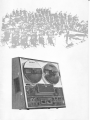
THREE HEAD STEREO TAPECORDER
TC-366
owner's instruction manual
-I
is a solid state 4-track stereo tape
deck designed for serious home recordists. The highly develop.
The SONY Model TC-366
ed fdcilities of the TC-366 will offer a new world of
when used in conjunction with high fidelity components.
Special features are
:
sound
scrape filter which eliminates tape modula.
tion distortion; tape tension regulator to reduce flutter and
wow; noise suppressor to cut off high frequency noise; automatic shut-off mechanism ; tape selector for low.noise highoutput tapes ; facility for mic and line mixing ; slant cabinet
designed for convenience of operating in either horizontal or
'{'
vertical use.
Before operating, read this manual carefully to become familiar
with all features and.operating procedures so as to realize the
full capabilities of TC-366. Keep this manual handy for future
reference.
ll
a
\(i.\\:
.l,r
PRECAUTIONS
Always keep the heads clean. Dust and deposits of f oreign
matter on the heads will affect sound quality of recording and
playback. For maintenance, refer to page 8.
1.
2.
The Function Selector of the TC-366 cannot be locked
without threading tape, because the Automatic Shut.off
Mechanism is activated in that condition.
The Microphone lnputs and the Auxiliary lnputs of this
recorder can be used simultaneously for mixing To record
only through the Microphone lnputs, disconnect any input
source from the Auxiliary lnputs; and vice versa.
2
Turn the Function Selector to STOP position and switch the
power off when the recorder is not being used.
4. Keep the recorder in a well ventilated area and away from
any excessive heat.
5. Do not block the ventilation grille at the back of the recorder
as this may stop ventilation and cause excessive heat inside
the
recorder.
TABLE OF,GONTENTS
Location of Controls and Connectors
Connections..
Operation of Controls
Tape Threading................
Recording Procedure
Playback Procedure
Mixing........
Sound-on-sound Recording
Erasing Tape ...........
Splicing Tape...........
Maintenance
Guide for Checking Troubles
Specifications
Circuit Diagram ................
Warranty
................
1
2
3
4
4
6
6
7
8
B
B
..... 11
......... 12
.......... 13
...............
14
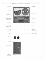
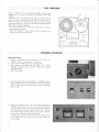
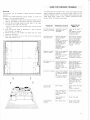
LOCATION OF CONTROLS AND CONNECTORS
ITAPE SPEED]
Tape Speed Selector
Reel Spindles
Tape Counter
[<<
ItNST srop]
lnstant Stop Lever
INorsE
r
> >>l
Function Selector
ITAPE SELECT]
Tape Selector
SUPPRESS]
Noise Suppressor
IPowER]
Power Switch
IHEADPHONE]
Headphone Jack
Pilot
IMtc]
Lamp
Microphone lnputs
IDc^]
Lt\LVl
IMONrroR]
Record Levers
Monitor Switches
ILEVEL]
[REcoRD VOLUME]
Record Volume Control
Level Meters
Reel Caps
IAUX rN]
Auxiliary lnputs
IcND]
Ground Terminal
ILINE oUT]
Line Outputs
@6
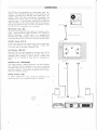
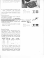
CONNECTIONS
The TC.366 can be connected to any high.quality audio components. The connections described in this booklet are for
connections between the TC-366 and other SONy audio components. When using other manufacture,s components, the
connections will be the same as for the SONy products in
almost all cases. To assure correct matching of the input and
output terminals of your sound system, refer to the specifica.
tions of the TC-366 (on page 12) and the instruction manual
provided with the components to be connected.
Microphone lnputs [MlG]
m
.lffiEr tl
lE-ll
''*-0"'tt ,ffi",.n,
These jacks will accept any high quality low impedance micro.
phone. SONY Microphone F-98 and ECM.21 are available as
optional accessories. A SONY radio or TV equipped with
recording jacks, SONY Telephone pick.up Tp-5S or SONy Stereo
Microphone Mixer MX-65 can also be connected to these jacks.
I
cord R( /4
A
Auxiliary lnputs IAUX lN]
Connect any external sound sources which have an output level
impedance is higher than
100k ohms and the frequency response is flat.
..."",,'",
of at least 0.06 volt. The input
Line Outputs [LINE OUT]
Having a 100k ohm load impedance and output level of 0.775
volt, these jacks can be connected to the tape inputs of an
integrated stereo amplifier or stereo receiver. Another tape
recorder can be connected to these jacks for duplication of
ta pes.
Headphone Jack [HEADPHONE]
This output accepts a stereo headphone of B ohms equipped
with a standard binaural headphone plug. Source monitoring
and tape monitoring can be done by selecting the setting of
the Monitor Switches. SONY Stereo Headphone DR.64 is avail.
able as an optional accessory.
[,cNs]
:::::i::l
:IITI::TT:::-::;iE:=
:t]lIr
:
IAUX rN]
i:
iLrNE
ourl
RK.7 4
Ground Terminal tcNDl
To reduce residual hum noise, connect this terminal to the
ground terminal of the connected amplifier or receiver.
.-'"5
il.
.!
:GND] , IEARTH.I
REC OUT.]
/-rY
nfL
v--t
?Ei
2
OPERATION OF CONTROLS
Tape Speed Selector ITAPE SPEED]
7)l ips and 33,1 ips are ideal for recording music when best
sound quality is desired. Ij( ips is ideal for speech especially
when longer recording time is desired.
ln playback mode, set the tape speed corresponding
to the
speed of the recorded tape.
. Change the tape speed only when the Function Selector is in
STOP position.
Tape Gounter
lndicates the approximate amount of tape used in recording or
playback. To reset the counter to [0000], press
Button at the left side of the counter.
the
Reset
lnstant Stop Lever ]NST STOPI
lnstantly stops tape motion while the recorder is in either record
or playback mode.
Pull the lever toward you until it locks in position. To release,
push it back slightly. The tape will immediately pick up normal
forward speed.
. When the Function Selector is turned to STOP position, the
lnstant Stop Lever will also be released.
Function Selector
Controls all tape motion.
FWD position ......to start the tape in either record or playback
mode.
STOP position......to stop the tape.
REW position ......1o rewind the tape.
FF position.........for fast forward tape motion.
Noise Suppressor INOISE SUPPRESS]
When this switch is set to the ON position during playback,
the distracting high frequency noise such as record scratch or
tape hiss is removed from the program material. This suppressor allows full pass-band for the major part of the audio
frequency range as it does not affect response frequencies
below 9 kHz.
Record Levers [REC]
For recording, pull the levers toward you, and while keeping
the levers in a Iocked position, turn the Function Selector to
FWD position. The lamps in the Level Meters will light, indicating
that the recorder is in record mode.
.When a monophonic program is desired, pull either L or R
lever toward you and turn the Function Selector to FWD
position.
Record Volume Controls IREC VOL]
For record volume level control, set the Monitor Switches to
SOURCE position and pull the Record Levers into locked posi'
tion. Then adjust the Record Volume Controls so that the
meters do not swing into the red area except on volume peaks.
The upper two knobs marked AUX are for adjusting the input
lnputs; and the other two marked
MIC are for adjusting the input level through the Microphone
level through the Auxiliary
I
nputs.
Level Meters [LEVEL]
While recording (when setting the Monitor Switches to SOURCE
position), the swing of the needles indicates the level of input
signals. During playback (when setting the Monitor Switches
to TAPE position), the meter indicates the output level at Line
O
utp uts.
Monitor Switches IMONITOR]
For playback of tapes, set the switches to TAPE position. While
recording, the TAPE position is for tape monitoring and SOURCE
position is for source monitorlng. The switch L and the switch
R rnay be activated separately.
Tape Selector [TAPE SELECT]
When you use SLH (SONY Low-noise High-output) tape, set this
selector to SPECIAL position. For standard tapes, set the
.-selector to NlORMAL oosition.
Scrape Filter
Stops vibration of the tape,
tortion and reduce flutter.
Tension arm
to eliminate tape modulation dis'
Tape Tension Regulator
Controlled by a guide pin located under the head cover. The
guide pin quickly responds to any subtle change of tape tension
so that a smooth, even flow of tape past the head assembley
is
assured.
Automatic Shut-off Mechanism
Activated by a wire lever under the
head cover. When the tape
is threaded, the tape contacts the lever and holds it in operating
position. lf the tape runs out or breaks, the lever will fall
forward and activates the shut-off mechanism which stops the
tape transport and turns the Function Selector
to
STOP position.
Automatic shut-off switch
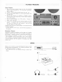
TAPE THREADING
Place an empty reel on the right reel spindle (Take.up Reel
Spindle) and a full reel on the left reel spindle (Feed Reel
Spindle).
Thread the tape from left to right by passing it underthe head
cover and wrap the tape around the hub of the right reel or
insert the end of the tape into the reel slot. Turn the reels
a few times to take up the slack so that the Automatic Shut-off
Mechanism is ready
' lt is
'
to activate.
recommended that reels of the same size are used for
both supply and take.up.
. When the recorder is used vertically, use the supplied reel
caps to secure the reels in place.
,,'i
5. ,/
UV
^v
,1U'
EcxoD
()
.\,/
EE
= LtLl
l-t
l-t
^ tr trE
... . Lt!jlt){ o
RECORDING PROCEDURE
Stereo Recording
1. Connect the desired source program to the input con.
nectors. Refer to 'Connections' on page 2.
2. Turn on the TC-366 and the source equipment.
3. Set a tape and an empty reel with side 1 up. Thread
the tape and set the Tape Counter to [0000] by pressing
4.
5.
the Reset Button.
Select tape speed.
Set the Tape Selector to either SPECIAL or NORMAL position.
Set it to SPECIAL position when SONY Low-noise High-output
tape is used, and to NORMAL position when a standard
tape is used.
6.
Adjust the recording level. Set the Monitor Switches to
SOURCE position and turn the Record Volume Controls.
The input level through the Auxiliary lnputs can be adjusted
with the upper two control knobs marked AUX; and the
input level through the Microphone lnputs can be adjusted
by the other two control knobs marked MlC.
ln either case, adjust the level so that the pointers of the
Level Meters do not go into the red area except on
volume peaks.
I
=.---;
^
5
e
:
i
_-
in the Level lvleters
in record mode.
f
rviil
8. At the
end of the tape, set the Function Selector to STOP
position. To record on side 2 (track 4 and 2), do not
rewind the
tape.
VOL
Reverse reel positions and repeat step 7.
1\
(,
When side 2 recording is finished, do not rewind the tape but
reverse reel positions. Then the tape will be ready for playback
(\
-t-
of tracks 1 and 3.
Monitor while recording
The professional feature of separate record and playback heads
permits monitoring of tape during recording by setting the
Monitor Switches to TAPE position.
With the use of a stereo headphone, in
of sou
d tape is possible by setting th
The source signal
in
SOURCE position. The
recorded signal (playback head output) is monitored when the
switches are in TAPE position.
.When the amplifier being used is equipped with a tape
monitor selector, sourceT'tape comparison can be done with the
amplifier. ln such case, the Monitor Switches on the recorder
should be in TAPE position.
is
m--6ntored when
when the switdhE-a7C
s
lnvert
:fd
Monophonic Recording
changing from left channel to right channel, reconnect the
source signal to the right channel input, adjust the right Record
Volume Control, and while holding the right Record Lever in
locked position, set the Function Selector to the FWD position.
For orientation of recording track and channel, refer to the
chart below. At the end of each track, do not rewind the tape.
Reverse reel positions.
Recordinei Upper side
lnput
-Lock the
Lever
track
of the tape connection Record
.
Track 1
Side
Track 4
Side 2
Track 3
Side
Track 2
Side 2
1
to L input
1
to R input
With the use of the independent Record Levers for each
channel, the TC-366 provides the facility to playback one
track (ex. track-1) while recording the other track (ex. track-3).
This feature will be ideal for language students who wish to
listen to a prerecorded lesson on one track while recording the
answers or repetition on the other track. Both tracks can later
be played back separately or simultaneously for comparison.
reverse ilrc i:pe
€ctro EFe ecT
deAD
Tltp,oqqH
a'
Pllonc#
ffioo
tL_
The sequence of monophonic recording should be track 1,
track 4, track 3 and track 2. Monophonic recording employs
either channel left or right at one time. Therefore, when
R
it
iR
1
2
3
4
rffi
i rr
rrl
PLAYBACK PROCEDURE
Stereo Playback
1. Set up the
stereo playback system and turn the operating
power of each component on. For connection inf ormation,
refer to page 2.
2. Thread a -track stereo recorded tape with side 1 up.
3. Set the Tape Speed Selector O to the required speed of the
recorded tape.
4. Set the Tape Selector @ to SPECIAL or NORMAL position
according to the sort of tape used, and the Monitor Switches
@ to TAPE position.
5. Set the Function Selector @ to FWD position. playback of
track l and 3 will start.
6. At the end of the tape, set the Function Selectar to STOp
position. To playback side 2 (track 4 and 2), do not rewind
the tape, but reverse the reel positions. Then set the
Function Selector to FWD position.
Playback sound volume and tone quality are controlled with the
connected amplifier.
. lf high frequency noise occurs, set the Noise Suppressor to
ON position.
Monophonic Playback
Monophonic playback procedures are the same as for stereo
playback, except for the controls at the amplifier connected to
this recorder. Playback sequence of each track should conform
to the sequence of recording; i.e. track I, 4, 3, 2. For tracks
1 and 4 playbark, set the mode selector and/or other controls
of the amplifier to reproduce the left channel only. For tracks
3 and 2 playback, set
channel only.
the amplifier to reproduce the right
MIXING
Mixing can be made by using the Microphone lnputs and the
Auxiliary lnputs simultaneously. For recording procedure, refer
to 'Recording Procedure' on page 4.
. The mixed sound can be monitored through a stereo headphone.
to recording outputs
Connect
LAUX
IN
]
ng corci
RK.74
SOUND.ON-SOUND RECORDING
This means making a mixed recordiog on one tape track, composed of a signal previously recorded on another track and'
a new external signal through one of the Microphone lnputs.
This facility of the TC-366 enables one person to record a duet,
a trio or other special effects.
Sound-on-sound recording on the right channel [L-R]
1. Record basic source material (A) on track I of the left
channel according to 'Monophonic Recording' on page 5,
and rewind the tape to the beginning.
2. Plug the supplied connecting cotd RK-74 into the Line
Output L and the Auxiliary lnput R of the TC.366.
. Be sure to use the plugs of the same color at both ends
of the connecting cord.
3. Plug an 8 ohm stereo headphone into the Headphone Jack,
and a low impedance microphone into Microphone lnput R.
4. Set the Monitor Switch R to SOURCE position. Adjust the
recording level after setting the left Record Volume Controls
to MIN position.
. Playback the tape and adjust level of the signal through
the Auxiliary Input R by using the Record Volume Control
AUX R and the right Level Meter. Rewind the tape.
. Lock the Record Lever R and adjust level of the signal
through Microphone lnput R by using the Record Volume
Control MIC R and the right Level Meter.
5. While keeping the Record Lever R in locked position, set
the Function Selector to FWD position and start recording
(B) with the microphone.
IL|NE
ourl :Ll
the left headphone, the playback of the basic
recording (A) on the left channel is heard; and through
the right headphone, the composite recording (A+B) is
heard. The composite signal (A+B) will be recorded on
Through
6.
l\4icrophone (low impedance)
track 3 of the right channel.
When the recording is finished, rewind tape to the beginning
and playback track 3.
. Be sure to re-set the Monitor Switch R to the TAPE posi-
tion for playback track 3. To listen through the headphone, set the Monitor Switch R to TAPE position and
Sound.on-sound i
L-R]
the Switch L to SOURCE position.
.1
2
3
4
V
Sound-on-sound recording on the left channel [R+L]
The mixed sound (A+B) can be recorded again onto track 1of
the left channel with another new sound (C). Reconnect the
connecting cord RK.74 to the Line Output R and the Auxiliary
lnput L. Repeat the sound-on-sound recording procedure by
using the controls of the left channel.
-+
1
2
4
{t}
nov/ being
" Portion
recorded.
ERASING TAPE
The erase head operates in record mode, therefore every time
a recording is made, any previous recording on the tape is
automatically erased. A tape can also be erased without adding
a new recording as follows.
1. Thread the tape to erase.
2. Disconnect any input source from the recorder, and turn
all Record Volume Controls fully counterclockwise.
3. Set the recorder in record mode. Now the tape is being
erased. Tape speed of 7)( ips is recommended.
. For fast erasure, use a bulk eraser.
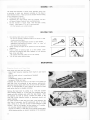
SPLICING TAPE
Use splicing tape and a pair of scissors.
. Do not use ordinary cellophane tape as
2.
diagonally.
3.
it tends to
dete'
riorate recording tapes.
. Also avoid using magnetized scissors or razor blades.
Magnetized instruments will cause a " click " or " pop " at
the splice during playback.
Neatly overlap the tapes to be spliced and cut the position
Place
a
piece
of
splicing tape on
a flat surface.
place the two diagonal tape ends together on
Then
the splicing
tape, shiny side down.
. Be careful thet ends meet, but do not overlap.
Trim off the excess splicing tape.
MAINTENANCE
Dirty heads and tape path will cause:
. Loss of high frequency response which results in poor sound
quality
.Loss of sound volume in recording and playback
' Drop-out
. Unsatisfactory results in tape erasing
.lncrease of flutter and wow.
Therefore the mirror-like finish on the face
tape path must be preserved
of all heads and
to get optimum performance.
Generally cleaning heads after every B hours will be sufficient'
But it is recommended to clean carefully the heads and tape
path before starting a valuable recording.
the head cover by pulling it up. Take the supplied
Head Cleaning Ribbon or a soft cloth and carefully wipe the
heads and other surfaces upon which the tape travels. when
the deposits are hard to remove, moisten the ribbon or the
cloth with a head cleaning solution or denatured alcohol and
repeat cleaning.
For easier access to clean the pinch roller, push backward the
wire lever of automatic shut-off mechanism and fix it there
with a string or so, and then set the Function Selector to FWD
position; and for the capstan, set the selector to FF position.
.Do not allow metallic materials near the heads.
. Discard the ribbon or cloth after use to prevent contamination
of the cleaning solution or alcohol remaining in the container.
Remove
8
This recorder is equipped with the non-magnetizing record
head. However, through continuous use residual magnetism
will gradually build up on the playback head and cause annoy.
ing back-ground noise. Therefore, periodic use of the SONY
Head Demagnetizer HE-2 (optional accessory) or equivalent is
recom mended.
Clean the cabinet with a soft cloth moistened with soapsuds.
Do not use solvents such as benzine or thinner as they may
cause damage of the cabinet.
,-U
^f(6\
To maintain the optimum performance of the recorder, lubrica-
tion is required every 6 months.
Consult your nearest SONY/Superscope service station for lubri"
cating the following parts of your recorder.
Use light machine oil and lubricate the capstan, pinch roller
shaft and idler shafts. Avoid excessive lubrication. lt will cause
slippage of the mechanism and contamination of your tape.
Make sure all excess oil is wiped off completely. Remove the top
panel and take out the caps of the pinch roller and the idler
shafts. Lubricate the capstan, the idler shafts and the pinch
roller shaft with 1 drop each of light machine oil.
. Before removing the top panel, disconnect the AC plug.
\7
[)
Pull out the Head Cover, Function Selector and four Record
Volume Controls. To remove the lnstant Stop Lever, turn the
lever clockwise. Remove the two screws of the top panel and
three screws under the Head Cover.
idler
shaft i2
capstan
I
E
@
3
prnch roller
$$
-r
es I
a
c
\2
&
3
eg
9
Vertical Use and Horizontal
1.
2.
3.
4.
Remove
Use
the bottom panel of the cabinet by unscrewing
four rubber
bases.
Remove the wooden case by loosening the four large screws
on both sides of the case. (Fig. 1)
Shift the direction of the wooden case.
For vertical use, make the wide, rubber'base side come to
the amplifier section of the deck. (Fie. 3)
For horizontal use, make that side come to the reel'shaft
section of the deck. (Fie. )
After tightening the four screws on both sides, place the
deck with top panel up and check whether or not the deck
is properly fixed.
5.
lf readjustment is neccessary, turn the deck upside'down
and loosen the four screws located at the encircled parts
on Fig. 2. The deck can be moved slightly.
Replace the bottom panel and the four rubber bases.
. Attach the supplied Reel Caps on the reel spindles when
using the set vertically.
e
Fig.
Fig
10
Fig.
3
Fig.
4
1
2
GUIDE FOR CHECKING TROUBLES
Mounting
This recorder can be installed in either vertical or horizontal
pos
ition.
Consult your SONY,rSuperscope service station
recorder in the following procedure.
1.
2.
to
mount the
4.
5.
made these tests, consult your nearlest
Take out the top panel as described in 'How to remove
the top panel' on page 9.
Mount tne deck in new location and fasten with four wood
screws as illustrated.
Place the top panel on top of the deck and replace the
parts and controls on it.
SONY/Superscope
service station for further instructions.
Make a rectangular cutout at the desired location on the
panel or the cabinet in accordance with the measurement.
Unscrew the four large screws on both sides of the case,
and remove the case from the deck.
. Before removing the case from the deck, disconnect the
AC plug.
3.
lf trouble with the TC.366 arises, make the following simple
tests to determine whether or not the trouble requires a pro.
fessional engineer's skill. lf the trouble persists after you have
rRouBLEs
PRoBABLE
cAusEs
*xfJ,Jro,?o
Function Selector . Automatic Sfrut.off . Take up tne .i".f, ot
cannot be locked Mechanism is
tape.
.The selector cannot
activated.
be locked without
threading tape.
No sound from
recorded
tape
'Monitor Switches . See that all controls
set in SOURCE are in proper position.
.Check connections.
position.
.Break in connection 'play commercially
to speakers or in
cord
from recorder to
amplifier.
connecting
. Amplifier fault or
volume control
turned off.
tape;
flutter
Slippage of
wow or
prerecorded tape to
see if the f ault is in
record or playback
circuit.
. Dirty or oily capstan . Clean capstan, pinch
and pinch roller.
roller and other tape
.Bent reel.
path components.
. Different size reels . Replace the bent reel.
.Check
pinch roller
for supply and
take-up.
for perfect roundness.
.Uneven pinch roller.
Recording can not . lnput
be
F
e
E
e
F
E
made
connections . Check input
connec-
are not p.roper, or tions a.nd c.ords.
break in the con- . Check Level Meters to
nectins cord.
cord
nectrng
see that signal is
. Amplifier fault.
reaching recorder.
I arrarc
- Paanzrl
Record Levers
not . See that all controls
locked.
are correct
Low hum on tapes . lnput (record player . Check whether hum
or tuner) or recorder occurs on prerecorded
not properly ground- tapes as well as those
made on the recorder.
ed.
' Recorder operating ' Checkground terminal
connections of input
in etectrical field.
or recorder.
. Try reversing the AC
power plug of the
recorder in the wall
o utlet.
Loss
of
high
. Dirty heads.
freq uen cies
h
to page
8)
. Thread tape properly.
ea ds)
. Tape twisted or
.Check the tape.
. Dirty erase head-
. Clean erase head
(Refer to page 8)
o"T"*1.
U n sati sfactory
erasi ng
path.
(Refer
. Tape threaded im
properly. (Shiny
side contacts the
ur_-lt----tDlx
- tyo 4l
. Clean heads and tape
11
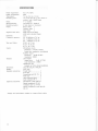
SPECIFICATIONS
Power requirement :
Power consumption :
Tape speed:
Recording time :
AC 117V, 60Hz
30w
7 % ips, 3% ips, tJ( ips
1.5 hours total at 7)lips, stereo re-
Reels
cording (with 1,800ft tape)
7" or smaller
:
Transistors 27, diodes 4
4 track stereo or monaural
Semiconductors :
Recording system:
Heads
:
Signal-to.noise ratio
:
Distortion :
Frequency response:
Record head 1
Playback head 1
1
Erase head
55dB (with SLH tapes)
52dB (with standard tapes)
r.2%
20 -Z5,OOOHz at 7% ips
30 - 17,O00H2 al 3% ips
30-
Wow and f lutter
:
lnputs:
Outputs
aI L%ips
Tllips
O.12% at 3ti ips
O.L7% at I](ips
9,000H2
O.O9% at
Microphone inputs
:
Sensitivity -72 dB (0. 19mV)
Accept low impedance microphones
Auxiliary in puts
Sensitivity -22 dB (0.O6V)
lmpedance L0OkO
Line outputs
O dB (O.775V)
Output level
Load impedance 1OOkQ
Headphone jack
Accepts an 8 ohm stereo headphone
Dimension :
Weight:
Supplied accessories:
|
6 /'u (W)
22lb
x a y'" (H) x I 4Yr6
8 oz
Empty Ree1.....................
1
SLH tape........................ I
Connecting cord RK-74... 2
Reel caps ..................... 2
Head cleaning ribbon...... 1
Dust protector DP-3 ......
Optional accessories:
t
(D)
1
Microphone F-98, ECM-21
Stereo headphone DR-6A
Telephone pick-up TP-5S
Stereo microphone mixer MX-6S,
MX_12
. Design and specifications subject to change without notice.
L2
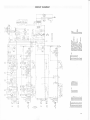
CIRCUIT DIAGRAM
L
t-
F-
l.:J
a: r0rf,
lOt rtrl
r/0t
r]]E
J
oE
^U
.=LLLL=LLrL
0tr]
X<LLLULLIL
NFooozoooo
@
:'itl
3s
ili:
tuil
lDt:
3
?=
I
OI
F-O
EE
CP
I;
Or
g
;6
!F3-rl rrr
a=qFF!:rY9r
:dool
1
-
n3q;;!E=5t
N66oo!t3Ij*=
jFuFz"'.afr'a
453H5[!:5!
u>Ztr>Fo(L<(D
N
o
o*-ruo+oo
€)oooooo
.ENNNNNN
a -----sdNO+6O*fr+@
';oooooooooo
>iiHidHOO6O
oaa6aaaaaaa
le !,
.
I?;,t:
rh:
rll
l -
<<+
o++doo
NOOONN
6@@iO6
OOOOOO
aa6Aaa
NNNNNN
o
N
.-i*No+b
HoOOOO
ioooao
o
oooooo
-diOOi*oHO
NNONNNNNTN
@6@O@@60@6
OOOOOOOOOO
aa(naaa6aao
NNNNNNNNNN
.\
qe
az
-:
zO<
FR
dA
f,
;a
o<
o iNoto@Nooo
€oooooooooH
.9NNNNNNNNNN
o--c iNa+o@Nooo
G OOOOOOOOOH
F OOOOOOOOOO
13
All parts of this SONY Recorder are fully guaranteed for a period of ONE YEAR
from date of purchase, providing that such purchase is made from an authorized
Superscope distributor or dealer and that the Warranty Registration Card is submitted
to Superscope, lnc. within ten days from date of purchase. This Warranty additionally
entitles you to free labor service for a period of ninety days from date of purchase.
This guarantee is valid only if repairs are effected by an authorized SONY/Superscope
Service Station. lf it is necessary for you to send this recorder or any defective part
to Superscope, lnc-, all shipments must be prepaid. lf your requested repairs and/or
parts exchange are within the terms of this Warranty, Superscope will prepay return
shipping charges, provided it is addressed within the continental limits of the United
States. This Warranty is void if the Serial Number has been altered or removed.
This Warranty shall not apply if the instrument has not been connected or operated
in accordance with the instructions furnished by SONY and Superscope. ThisWarranty
shall also be voided if the instrument has been altered or repaired in any way that
Superscope believes has affected the stability or reliability of the instrument. To
protect your rights under this Warranty, fill out and mail the Warranty Registration
Card to Superscope within 1O days of the purchase date. There is no implied
warranty of merchantibility with respect to this recorder, nor are there any other
warranties which extend beyond the description on the face hereof.
The soNY corporation and/or Superscope, lnc. reserves the rightto make changes
in design and/or improvements upon its products without any obligation to install
these changes upon any of its products theretofore manufactured.
t4