1
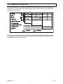
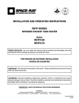
INFRARED RADIANT HEATER DK SERIES CERAMIC HEATERS NATURAL GAS (CHECK ONE) PROPANE GAS PROJECT: ARCHITECT/ENGINEER: CONTRACTOR: DATE: NAME: ADDRESS: NAME: ADDRESS: NAME: ADDRESS: SUBMITTED BY: EQUIPMENT USED: ACCESSORIES: Chain Mounting Kit Thermostat Gas Pressure Regulator Parabolic Extension Submittal ♦ DK Gas Shut-Off Valve Reverb Screen Other Other Jun-10 1) GENERAL INFORMATION This heater is a self-contained infrared radiant ceramic heater for use in locations where flammable gases or vapors are not generally present (as defined by OSHA acceptable limits) and is intended for the heating of nonresidential spaces. INSTALLATION REQUIREMENTS Installation of this heater must be in accordance with all applicable codes shown in the instructions and/or the local codes and authorities having jurisdiction. In Canada, the installation must conform to current CAN/CGA-B149.1/2 Installation Code in the absence of local codes. Heaters shall be installed by a licensed contractor or licensed installer. Clearances to combustibles as outlined in this manual should always be observed. In areas used for storage of combustible materials where they may be stacked below the heater, NFPA54 requires that the installer must post signs that will “specify the maximum permissible stacking height to maintain the required clearances from the heater to combustibles.” Every heater shall be located with respect to building construction and other equipment so as to permit access to the heater. Each installer shall use quality installation practices when locating the heater and must give consideration to clearances to combustible materials, vehicles parked below, lights, overhead doors, storage areas with stacked materials, sprinkler heads, gas and electrical lines, and any other possible obstructions or hazards. Consideration also must be given to service accessibility. The heater, when installed in aircraft hangars and public garages, must be installed in accordance with ANSI/NFPA 409-latest edition (Standard for Aircraft Hangars), ANSI/NFPA 88a-latest edition (Standard for Parking Structures), and ANSI/NFPA 88b-latest edition (Standard for Repair Garages) with the following clearances: a. At least 10 feet above the upper surfaces of wings or engine enclosures of the highest aircraft that may be housed in the hangar and at least 8 feet above the floor in shops, offices, and other sections of hangars communicating with aircraft storage or service areas. b. At least 8 feet above the floor in public garages. ▲WARNING: Minimum clearances marked on the heater must be maintained from vehicles parked below the heater. (FOR CANADA ONLY) a. Installation of this appliance is to be in accordance with the latest edition of CAN 1-B149.1llation Code for Natural Gas Burning Appliances and Equipment), and/or CAN B149.2 (Installation Code for Propane Gas Burning Appliances and Equipment). b. For installation in public garages or aircraft hangars, the minimum clearances from the bottom of the heater to the upper surface of the highest aircraft or vehicle shall be 50 percent greater than the certified minimum clearance, but the clearance shall not be less than 8 feet. Although these heaters may be used in many applications other than space heating (e.g., process heating), GasFired Products, Inc. will not recognize the warranty for any use other than space heating. This heater is for Indoor Installation only and can be used in unvented mode. The term Unvented actually means Indirect Vented. While the products of combustion are expelled into the building, national codes require ventilation in the building to dilute these products of combustion. This ventilation may be provided by gravity or mechanical means. This heater is not an explosion proof heater. Where the possibility of exposure to volatile and low flash point materials exists, it could result in property damage or death. This heater must not be installed in a spray booth where the heater can operate during the spraying process. Consult your local fire marshal or insurance company. ▲WARNING: Certain materials or objects, when stored under the heater, will be subjected to radiant heat and could be seriously damaged. Observe the Minimum Clearances to Combustibles listed in the manual and on the heater at all times. SUBMITTAL ♦ DK 1 Jun-10 2) MINIMUM CLEARANCES TO COMBUSTIBLES Minimum clearances shall be measured from the outer surfaces as shown below: MINIMUM CLEARANCES TO COMBUSTIBLES Mounted Horizontally BELOW MODEL SIDES CEILING w/Standard Reflector w/Reflector Extension Mounted at 35º Angle BELOW FRONT w/Standard Reflector w/Reflector Extension w/Standard Reflector w/Reflector Extension REAR Angle Mounting (degree) DK30 DK33 DK35 DK40 30” 36” 72” 100” 72” 100” 36” 50” 30” 0º min 35º max DK60 DK66 DK70 DK80 48” 48” 98” 137” 98” 137” 48” 68” 36” 0º min 35º max DK100 DK120 48” 64” 128” 180” 128” 180” 60” 84” 48” 0º min 35º max DK132 DK160 DK140 60” 64” 136” 190” 136” 190” 64” 90” 48” 10º min 35º max The clearances specified above must be maintained to combustibles and other materials that may be damaged by temperatures 90ºF above ambient temperature. It is the installer’s responsibility to ensure that building materials with a low heat tolerance which may degrade at lower temperatures are protected to prevent degradation. Clearances to combustibles are posted on the reflector near the control end of the heater. In locations used for storage of combustible materials where they may be stacked below the heater, NFPA 54 requires that the installer must post signs that will “specify the maximum permissible stacking height to maintain the required clearances from the heater to combustibles.” Space-Ray recommends posting these signs adjacent to the heater thermostat or other suitable location that will provide enhanced visibility. NOTE: SUBMITTAL ♦ DK 2 Jun-10 3) SPECIFICATIONS MODEL NO. DK30-N5B DK35-N5B DK40-N5B DK60-N5B DK70-N5B DK80-N5B DK100-N5B DK120-N5B DK140-N5B DK160-N5B DK33-L5B DK66-L5B DK100-L5B DK132-L5B Gas Type: N = Natural L = Propane BTU/HR INPUT 33,000 35,000 40,000 65,000 70,000 80,000 100,000 120,000 140,000 160,000 33,000 66,000 99,000 132,000 NUMBER OF BURNERS Natural Gas Propane Gas SHIPPING WEIGHT MINIMUM MOUNTING HEIGHT (feet) 1 1 1 2 2 2 3 3 4 4 1 2 3 4 3/32” #41 #38 3/32” #41 #38 #41 #38 #41 #38 n/a n/a n/a n/a n/a n/a n/a n/a n/a n/a n/a n/a n/a n/a #52 #52 #52 #52 30 lbs. 30 lbs. 30 lbs. 35 lbs. 35 lbs. 35 lbs. 48 lbs. 48 lbs. 58 lbs. 58 lbs. 30 lbs. 35 lbs. 48 lbs. 58 lbs. 11 12 12 13 13 14 15 16 17 18 11 13 15 17 ORIFICE SIZE GAS-PIPE CONNECTION: MODEL SUFFIX Ignition System: 5 = Direct Spark (115 Volt / 0.40 Amp / 60 Hz) One Orifice Per Burner 1/2” NPT (Female) *MOUNT HEATERS AS HIGH AS POSSIBLE. Minimums are shown as a guideline for human comfort and uniform energy distribution for complete building heating applications. Consult your Space-Ray representative for the particulars of your installation requirements. 4) DIMENSIONS SUBMITTAL ♦ DK 3 Jun-10 5) OPTIONAL PARABOLIC REFLECTOR EXTENSION ASSEMBLY The heater is completely factory assembled and requires no field assembly. If the optional parabolic reflector extension is utilized, locate and identify the end panels and side panels as shown in the following diagram. Attach the side panels as shown. Attach the end panels so that the end flanges of the end panels overlap the side panels. Attach the side panels and end panels together with the screws provided in the kit. Attach the remaining screws as shown in Detail A. This is to ensure that the Parabolic Reflector Extension is securely attached to the reflector. The clearances to combustibles (shown on the clearance label that is secured to the reflector on the control end of the heater and in Section 4 of these instructions) must be closely observed. 6) GAS CONNECTION If the maximum supply pressure is less than ½ psig, a second stage regulator is not required. SUBMITTAL ♦ DK 4 Jun-10 7) GAS PRESSURE TABLE GAS PRESSURE TABLE SUPPLY PRESSURE GAS TYPE MANIFOLD PRESSURE Minimum Maximum DK (30, 35, 40, 60, 70, 80, 100 120, 140 & 160) Natural 6” W.C. 7” W.C. 14” W.C. DK (33, 66, 100 & 132) Propane 10” W.C. 11” W.C. 14” W.C. HEATER MODEL Minimum permissible gas supply pressure for purpose of input adjustment. 8) ELECTRICAL CONNECTIONS TYPICAL HEATER WIRING DIAGRAM FOR DIRECT SPARK IGNITION SYSTEM SUBMITTAL ♦ DK 5 Jun-10 9) VENTILATION Where unvented infrared heaters are used, natural or mechanical means shall be provided to supply and exhaust at least 4 cfm per 1000 Btu per hr input of installed heaters. Exhaust openings for removing flue products shall be above the level of the heaters. This heater requires ventilation in the building to dilute the products of combustion and provide fresh air for efficient combustion. Power ventilation is recommended and the minimum vent flow required is as follows: DK30, DK33, DK35 DK40 DK60, DK66, DK70 DK80 140 cfm 160 cfm 280 cfm 320 cfm DK100 DK120 DK132, DK140 DK160 400 cfm 480 cfm 560 cfm 640 cfm If gravity ventilation is used, the required square feet of inlet and outlet vent area (depending on height and temperature difference) is as follows: DK30, DK33, DK35 DK40 DK60, DK66, DK70 DK80 0.49 s/f 0.57 s/f 0.98 s/f 0.98 s/f DK100 DK120 DK132, DK140 DK160 1.48 s/f 1.72 s/f 1.97 s/f 2.30 s/f The General Ventilation Rules outlined in ASHRAE GUIDE AND DATA BOOK should be observed when locating vents. Exhaust vents must be located at the highest point above and in the vicinity of the heaters and the inlet vents must be located below the level of the heaters. Local codes may require that mechanical exhaust systems be interlocked with the function simultaneously or allow control of exhausters to humidistat. SUBMITTAL ♦ DK 6 Jun-10 10) SEQUENCE OF OPERATION The chart below shows the sequence of operation for the normal operating cycle of the heater when connected to a permanent 120V power supply and the heater is turned on and off by a remote 120V thermostat. (See Section 10) If the flame is not sensed during sequence T2 then the burner will automatically begin re-ignition sequence T1. The ignition sequence will be repeated three times with a 15 second inter-purge. If the flame is not reestablished the heater will go to lockout. SUBMITTAL ♦ DK 7 Jun-10 11) LIMITED WARRANTY LIMITED WARRANTY: Gas-Fired Products, Inc., the manufacturer, warrants to the original owner of any Space-Ray infrared gas heater that said heater will be free from defects in material or workmanship under normal use and service. The heater(s) shall be installed, used and maintained strictly in accordance with the manufacturer's instructions. The manufacturer's sole obligation under this warranty shall be limited to furnishing replacement parts, F.O.B. Charlotte, NC, for 12 months from the date of installation, or 18 months from the date of shipment by the manufacturer, whichever period shall expire first. Labor charges for removal of defective parts and the installation of the replacement parts are not included. This warranty applies only within the USA and Canada. WARNING: Manufacturer's warranty shall not apply: (a) to damage to the heater when used in an atmosphere containing halogenated hydrocarbons or other corrosive chemicals. Some compounds in the air can be ingested into the equipment and can cause an accelerated rate of corrosion of some of the parts of the heating components. The use of such chemical compounds in or near the operating environment of the heater should be avoided where a longer heater life is desirable; (b) to any heater or components which have been repaired or replaced with other than factory parts, modified in any way, misused or damaged, or which have been used contrary to the manufacturer's written instructions. Replacement parts are available through Space-Ray representatives or their distributors. LIMITATION OF WARRANTY: THERE ARE NO WARRANTIES, EXPRESS OR IMPLIED, WHICH EXTEND BEYOND THE DESCRIPTION ON THE FACE HEREOF. WITHOUT LIMITING THE FOREGOING, THE MANUFACTURER EXPRESSLY EXCLUDES ANY AND ALL IMPLIED WARRANTIES, INCLUDING BUT NOT LIMITED TO ANY IMPLIED WARRANTY OF FITNESS FOR A PARTICULAR PURPOSE AND ANY IMPLIED WARRANTY OF MERCHANTABILITY FOR ITS PRODUCTS. If any provision of this warranty is found to be void, unenforceable or unconscionable, then the same is hereby severed and the remainder of this warranty is hereby saved and shall remain in force. EXCLUSIVE REMEDY: The sole and exclusive remedy under this warranty is the replacement of the defective parts or heaters as hereinabove specified. THE MANUFACTURER DOES HEREBY EXPRESSLY EXCLUDE ANY AND ALL LIABILITY FOR INCIDENTAL AND CONSEQUENTIAL DAMAGES UNDER THIS OR ANY OTHER WARRANTY. Without intending to limit the aforesaid exclusion, THE MANUFACTURER DOES HEREBY EXCLUDE ANY LIABILITY UNDER THIS OR ANY OTHER WARRANTY FOR INJURIES AND COMMERCIAL LOSSES TO PROPERTY THAT RESULT FROM THE OPERATION, PROPER OR IMPROPER, OF ITS PRODUCTS. ADDITIONAL WARRANTY ON HEAT EMITTING SURFACE AND BURNER: Manufacturer warrants to the original owner of any CSA design certified heater that, if installed, used and maintained strictly in accordance with the printed instructions received with the heater, the manufacturer will at any time during the below listed time periods, furnish at no cost to the original owner, replacement emitters or burners which have become inoperative by reason of any defect in our workmanship, materials or construction. The manufacturer's obligation under this warranty shall be limited to furnishing replacements under the following time periods from the date of installation: DK Series: Emitter Burner 5 Years 1 Year The manufacturer will not be responsible for labor charges incurred for removal or installation of emitters. Any transportation charges involved in the return or repair are excluded. ADDITIONAL TERMS: Manufacturer assumes no liability for delay in performing its obligations under the aforesaid warranty. Manufacturer assumes no liability for failure in performing its obligations thereunder if failure results directly or indirectly from any cause beyond its control, including but not limited to acts of God, acts of Government, floods, fires, shortages of materials, strikes and other labor difficulties or delays or failures of transportation facilities. This is a Non-Residential product (excluding the CB Series which is certified for residential and non-residential use). Installation and service shall be by a Licensed Contractor and in accordance with National and Local Codes. When presenting warranty claims, proof of date of purchase must be submitted. No Representative is authorized to assume for the manufacturer any liability except as set forth above. SPACE-RAY® Post Office Box 36485 (28236) ● 305 Doggett Street (28203) ● Charlotte, North Carolina Phone (704) 372-3485 ● Fax (704) 332-5843 ● www.spaceray.com ● email: [email protected] SUBMITTAL ♦ DK 8 Jun-10