1
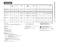
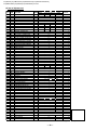
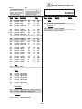
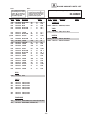
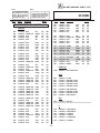
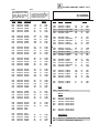
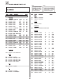
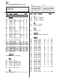
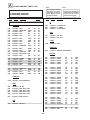
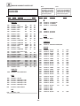
KV-[13M40/50/51], KV-[14MB40/40C/40A], KV-[20M40/S40/S41/V80], KV-[21SE40/40A/40C/80/80A/80C],
KV-[21MB40C/40M/40P], KV-[21ME40/40P], KV-[21SB40/40M/40P], KV-21XT4A
SELF-DIAGNOSTIC FUNCTION
SERVICE MANUAL
MODEL
KV-13M40
KV-13M40
KV-13M50
KV-13M51
KV-14MB40
KV-14MB40C
KV-14MB40A
KV-20M40
KV-20M40
KV-20S40
KV-20S40
KV-20S41
KV-20S41
KV-20V80
KV-20V80
COMMANDER
DEST.
CHASSIS NO.
RM-Y156
US
SCC-S01E-A
RM-Y156
CND
SCC-S03D-A
RM-Y156
US
SCC-S01G-A
RM-Y156W US
SCC-S01F-A
RM-Y156
E
SCC-S04P-A
RM-Y156
E
SCC-S04N-A
RM-Y156
E
SCC-S04Q-A
RM-Y156
US
SCC-S01A-A
RM-Y156
CND
SCC-S03C-A
RM-Y155
US
SCC-S01C-A
RM-Y155
CND
SCC-S03A-A
RM-Y156W US
SCC-S01B-A
RM-Y156W CND
SCC-S03L-A
RM-Y135A
US
SCC-S01D-A
RM-Y135A
CND
SCC-S03B-A
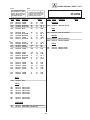
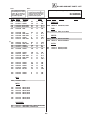
BA-4 CHASSIS
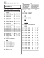
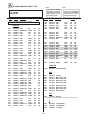
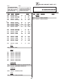
MODEL
COMMANDER
KV-21SE80A
KV-21MB40C
KV-21MB40M
KV-21MB40P
KV-21ME40
KV-21SB40C
KV-21SB40M
KV-21SB40P
KV-21SE80
KV-21SE80C
KV-21SE40
KV-21SE40C
KV-21SE40A
KV-21XT4A
KV-21ME40C
DEST.
CHASSIS NO.
RM-Y135A
E
SCC-S04M-A
RM-Y156
E
SCC-S04F-A
RM-Y156
MX
SCC-S02B-A
RM-Y156
E
SCC-S04E-A
RM-Y156
E
SCC-S04B-A
RM-Y155
E
SCC-S04H-A
RM-Y155
MX
SCC-S02A-A
RM-Y155
E
SCC-S04J-A
RM-Y135A
E
SCC-S04L-A
RM-Y135A
E
SCC-S04K-A
RM-Y155
E
SCC-S04A-A
RM-Y155
E
SCC-S04C-A
RM-Y155
E
SCC-S04D-A
RM-Y155
E
SCC-S04G-A
RM-Y156
E
SCC-S04W-A
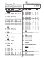
TRINITRON® COLOR TV
—1—
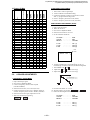
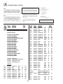
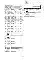
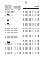
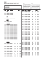
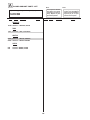
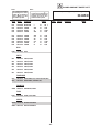
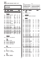
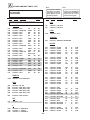
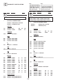
KV-
Power Requirements
Number of Inputs/Outputs
Video
1)
S Video 2)
13M40*
13M50**
13M51**
14MB40*
14MB40C*
14MB40A**
20M40
20S 40
20S41
21MB40M
21MB40P
21SB40P
21SB40M
21MB40C
21SB40C
21XT4A
20V80*
21SE80**
21SE80A
21SE80C
21ME40
21SE40
21SE40C
21SE40A
21ME40C
120V, 60 Hz
220V, 50/60 Hz
120V, 60Hz
120V, 60Hz
220V, 50/60Hz
120V, 60Hz
220V, 50/60 Hz
120V, 60 Hz
220V, 50/60Hz
2
2
2
2
2
2
2
-
-
-
1*/-**
-
-
-
2
2
2
2*/**
2
2
2
1*/2**
-
1*/2**
-
3)
1*/2**
Audio Out 4)
Speaker Output (W)
3W
3W
3W (M40)
3W x 2 (S40/41)
3W (MB40M/40P)
3W x 2 (SB40M/40P)
3W(MB40C)
3W x 2 (SB40C/XT4A)
1*/**
5W x 2
1
5W x 2
3W x 2 (ME40)
4W x 2 (SE40)
4W x 2 (SE40A/40C)
3W x 2 (ME40C)
75W
80W
85W (MB40C)
95W (SB40C)/(XT4A)
10W
105W
90W
95W
10W
80W (MB40M/40P)
90W (SB40M/40P)
8W
100W
8W
80W (M40 )
90W (S40/41 )
8W
8W
10W
8W
10W
358 x 342
x 401 mm
358 x 342
x 401 mm
522 x 477
x 479 mm
522 x 477
x 479 mm
522 x 477
x 479 mm
556 x 464.5
x 474.9 mm
556 x 464.5
x 474.9 mm
610 x 464.5
x 469..5 mm
610 x 464.5
x 469..5 mm
14 1/8 x 131 / 2
14 1/8 x 131 / 2
21 x 183 / 4
21 x 183 / 4
21 x 183 / 4
21 7/8 x 181 / 4
21 7/8 x 181 / 4
24 x 18
24 x 18
x 187/8
x 187/8
x 187/8
x 182/3 in.
x 182/3 in.
x 181/2 in.
x 181/2 in.
21.6 kg
48 lbs.
21.6 kg
48 lbs.
21.6 kg
48 lbs.
22.6 kg
49 lbs. 3 oz.
22.6 kg
49 lbs. 3 oz.
20.6 kg
45 lbs.
20.6 kg
45 lbs.
Audio
Power Consumption (W)
In use (Max.)
In standby
Dimensions (W/H/D)
(mm)
—2—
(in.)
x 153/4
Mass
(kg)
(lbs)
in.
10 kg
22 lbs.
1*/2**
x 153/4
in.
10 kg
22 lbs.
Television System
American TV Standard (all models except: KV-14MB40A/21SE40A/21XTA4/21SE80A)
PAL-M, PAL-N, NTSC (for KV-14MB40A/21SE40A/21XTA4/21SE80A only)
1)
1 Vp-p 75 ohms unbalanced, sync negative
( ) SRS (SOUND RETRIEVAL SYSTEM)
2)
Y: 1 Vp-p 75 ohms unbalanced, sync negative
C: 0.286 Vp-p (Burst signal), 75 ohms
The ( ) SRS (SOUND RETRIEVAL SYSTEM) is
manufactured by Sony Corporation under license
3)
Channel Coverage
VHF: 2-13 / UHF: 14-69 / CATV: 1-125
Picture Tube
Trinitron Tube
Visible Screen Size
13-inch picture measured diagonally
20-inch picture measured diagonally
Actual Screen Size
14-inch picture measured diagonally
21-inch picture measured diagonally
Antenna
75 ohm external terminal for VHF/UHF
Supplied Accessories
Remote commander (w/2 size AA (R6) batteries)
RM-Y156:
(KV-13M40/13M50/14MB40/20M40/21MB40M/
21MB40P/21MB40C/14MB40C/14MB40A/21ME40/21ME40C only)
RM-156W: (KV-13M51/20S41 only)
RM-Y155:
(KV-20S40/21SB40M/21SB40P)
21SB40C/21XT4A/21SE40/21SE40C/21SE40A only)
RM-Y135A: (KV-20V80/21SE80/21SE80A/21SE80C only)
Antenna Dipole (7 models)
(KV-21SE80A/21SE40A/21XT4A/13M40/13M50/13M51/14MB40A only)
Antenna Connector
(all models except: KV-20M40/20S40/20S41/21SE80/21SE80C/20V80)
Optional Accessory
Antenna dipole (KV-20M40/20S40/20S41 only)
4)
500 mVrms (100% modulation), Impedance: 47 kilohms
More than 408 mVrms at the maximum volume setting (variable)
from SRS Labs, Inc. It is covered by U.S. Patent No.
4,748,669. Other U.S. and foreign patents pending.
More than 408 mVrms (fix)
Impedance: 50 kilohms
The word 'SRS' and the SRS symbol ( ) are
registered trademarks of SRS Labs, Inc.
Design and specifications are subject to change
without notice.
Licensed by BBE Sound, Inc. under
USP 4638258.4482866. BBE and BBE symbol are
trademarks of BBE Sound, Inc.
(For KV-21SE80/21SE80A/21SE80C/20V80 only)
KV-[13M40/50/51], KV-[14MB40/40C/40A], KV-[20M40/S40/S41/V80], KV-[21SE40/40A/40C/80/80A/80C],
KV-[21MB40C/40M/40P], KV-[21ME40/40P], KV-[21SB40/40M/40P], KV-21XT4A
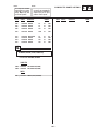
SPECIFICATIONS
KV-[13M40/50/51], KV-[14MB40/40C/40A], KV-[20M40/S40/S41/V80], KV-[21SE40/40A/40C/80/80A/80C],
KV-[21MB40C/40M/40P], KV-[21ME40/40P], KV-[21SB40/40M/40P], KV-21XT4A
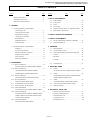
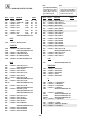
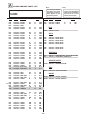
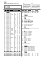
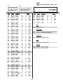
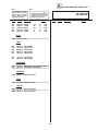
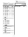
TABLE OF CONTENTS
Section
Title
Page
Warnings and Caution ..................................................... 4
Self-Diagnostic Function ................................................ 4
Safety Check Out Instructions ........................................ 7
1. GENERAL
1-1. Instruction Manual - English Edition
Connecting the TV.......................................................8
Section
Title
Page
3. SET-UP ADJUSTMENTS
3-1. Beam Landing............................................................. 20
3-2.
3-3.
Convergence............................................................... 21
Focus........................................................................... 22
3-4.
3-5.
Screen (G2)................................................................. 22
Method of Setting the Service Adjustment Mode....... 22
3-6.
White Balance Adjustments........................................ 22
Using the Remote Control ..........................................8
Setting Menu Language...............................................9
4. SAFETY RELATED ADJUSTMENTS......................... 23
Setting up your Channels............................................9
Watching the TV...........................................................9
5. CIRCUIT ADJUSTMENTS
Additional Features..................................................... 10
Troubleshooting...........................................................11
1-2. Instruction Manual - Spanish Edition
5-1.
5-2.
Electrical Adjustment by Remote Commander........... 25
A Board Adjustments.................................................. 27
6. DIAGRAMS
Instalacion................................................................... 12
Uso del Control Remoto............................................. 12
6-1.
Block Diagrams.......................................................... 29
6-2.
Circuit Boards Location.............................................. 32
Adjuste de Idioma de los Menus................................. 13
Programacion de Canales............................................ 13
6-3.
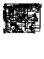
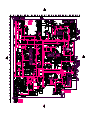
Printed Wiring Boards and Schematic Diagrams .......32
• A Board..................................................................... 33
• HZ Board ................................................................. 36
Otras Funciones...........................................................14
Solucion de Problemas................................................ 15
2. DISASSEMBLY
• C Board..................................................................... 40
6-4.
Semiconductors........................................................... 47
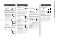
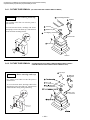
2-1-1. Rear Cover Removal ..................................................... 16
(KV-13M40/13M50/13M51/14MB40/14MB40A/14MB40C)
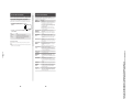
2-1-2. Rear Cover Removal...................................................... 16
7. EXPLODED VlEWS
7-1.
(KV-20M40/20S40/20S41/21MB40C/21MB40M/
21MB40P/21SB40C/21SB40M/21SB40P/21XT4A)
(KV-13M40/13M50/13M51/14MB40/14MB40A/14MB40C)
7-2 .
2-1-3. Rear Cover Removal..........................................................16
21SB40C/21SB40M/21SB40P/21XT4A)
7-3 .
(KV-20V80/21SE80/21SE80A/21SE80C)
2-2.
Chassis..........................................................................49
(KV-20M40/20S40/20S41/21MB40C/21MB40M/21MB40P/
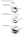
(KV-21ME40/21ME40C/21SE40/21SE40A/21SE40C)
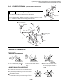
2-1-4. Rear Cover Removal ..................................................... 17
Chassis ..........................................................................48
Chassis..........................................................................50
(KV-21ME40/21ME40C/21SE40/21SE40A/21SE40C)
A Board Removal (for all models) ............................. 17
7-4 .
Chassis (KV-20V80/21SE80/21SE80A/21SE80C)................ 51
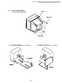
2-3. Service Position (for all models)................................17
2-4-1. Picture Tube Removal ................................................... 18
7-5.
Main Power Switch...................................................... 52
(KV-13M40/13M50/13M51/14MB40/14MB40A/14MB40C)
2-4-2. Picture Tube Removal................................................... 18
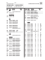
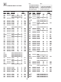
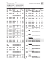
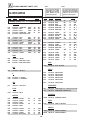
8. ELECTRICAL PARTS LIST
• Table of Contents for Parts List...................................53
• A Board Common Parts List....................................... 54
• A Board Variant Lists.................................................. 60
(KV-20M40/20S40/20S41/21MB40C/21MB40M/21MB40P/
21SB40C/21SB40P/21XT4A/21ME40/21ME40C/21SE40/
• C Board Parts List....................................................... 100
• HZ Board Parts List.....................................................101
21SE40A/21SE40C/21SB40M)
2-4-3. Picture Tube Removal.................................................. 19
(KV-20V80/21SE80/21SE80A/21SE80C)
—3—
KV-[13M40/50/51], KV-[14MB40/40C/40A], KV-[20M40/S40/S41/V80], KV-[21SE40/40A/40C/80/80A/80C],
KV-[21MB40C/40M/40P], KV-[21ME40/40P], KV-[21SB40/40M/40P], KV-21XT4A
WARNINGS AND CAUTIONS
CAUTION!
ATTENTION
SHORT CIRCUIT THE ANODE OF THE PICTURE TUBE AND
THE ANODE CAP TO THE METAL CHASSIS, CRT SHIELD,
OR CARBON PAINTED ON THE CRT, AFTER REMOVING
THE ANODE.
APRES AVOIR DECONNECTE LE CAP DE L'ANODE, COURT-CIRCUITER
L'ANODE DU TUBE CATHODIQUE ET CELUI DE L'ANODE DU CAP AU
CHASSIS METALLIQUE DE L'APPAREIL, OU AU COUCHE DE CARBONE
PEINTE SUR LE TUBE CATHODIQUE OU AU BLINDAGE DU TUBE
CATHODIQUE.
WARNING!!
ATTENTION!!
AN ISOLATION TRANSFORMER SHOULD BE USED
DURING ANY SERVICE TO AVOID POSSIBLE SHOCK
HAZARD, BECAUSE OF LIVE CHASSIS.THE CHASSIS OF
THIS RECEIVER IS DIRECTLY CONNECTED TO THE AC
POWER LINE.
SAFETY-RELATED COMPONENT WARNING!!
COMPONENTS IDENTIFIED BY SHADING AND MARK
¡ ON THE SCHEMATIC DIAGRAMS, EXPLODED VIEWS
AND IN THE PARTS LIST ARE CRITICAL FOR SAFE
OPERATION. REPLACE THESE COMPONENTS WITH
SONY PARTS WHOSE PART NUMBERS APPEAR AS
SHOWN IN THIS MANUAL OR IN SUPPLEMENTS
PUBLISHED BY SONY. CIRCUIT ADJUSTMENTS THAT
ARE CRITICAL FOR SAFE OPERATION ARE IDENTIFIED
IN THIS MANUAL. FOLLOW THESE PROCEDURES
WHENEVER CRITICAL COMPONENTS ARE REPLACED
OR IMPROPER OPERATION IS SUSPECTED.
AFIN D'EVITER TOUT RESQUE D'ELECTROCUTION PROVENANT D'UN
CHÁSSIS SOUS TENSION, UN TRANSFORMATEUR D'ISOLEMENT DOIT
ETRE UTILISÉ LORS DE TOUT DÉPANNAGE. LE CHÁSSIS DE CE
RÉCEPTEUR EST DIRECTEMENT RACCORDÉ À L'ALIMENTATION
SECTEUR.
ATTENTION AUX COMPOSANTS RELATIFS A LA SECURITE!!
LES COMPOSANTS IDENTIFIES PAR UNE TRAME ET PAR UNE MARQUE
¡ SUR LES SCHEMAS DE PRINCIPE, LES VUES EXPLOSEES ET LES
LISTES DE PIECES SONT D'UNEIMPORTANCE CRITIQUE POUR LA
SECURITE DU FONCTIONNEMENT. NE LES REMPLACER QUE PAR DES
COMPOSANTS SONY DONT LE NUMERO DE PIECE EST INDIQUE DANS
LE PRESENT MANUEL OU DANS DES SUPPLEMENTS PUBLIES PAR
SONY. LES REGLAGES DE CIRCUIT DONT L'IMPORTANCE EST CRITIQUE
POUR LA SECURITE DU FONCTIONNEMENT SONT IDENTIFIES DANS
LE PRESENT MANUEL. SUIVRE CES PROCEDURES LORS DE CHAQUE
REMPLACEMENT DE COMPOSANTS CRITIQUES, OU LORSQU'UN
MAUVAIS FONTIONNEMENT SUSPECTE.
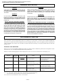
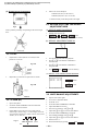
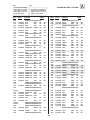
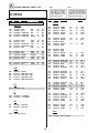
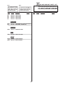
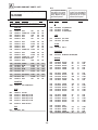
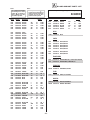
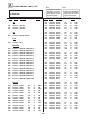
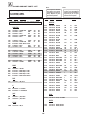
SELF-DIAGNOSTIC FUNCTION
The units in this manual contain a self-diagnostic function. If an error occurs, the STANDBY/TIMER lamp will automatically begin to
flash. The number of times the lamp flashes translates to a probable source of the problem. A definition of the STANDBY/TIMER lamp
flash indicators is listed in the instruction manual for the user's knowledge and reference. If an error symptom cannot be reproduced, the
remote commander can be used to review the failure occurrence data stored in memory to reveal past problems and how often these
problems occur.
DIAGNOSTIC TEST INDICATORS
When an error occurs, the STANDBY/TIMER lamp will flash a set number of times to indicate the possible cause of the problem. If there
is more than one error, the lamp will identify the first of the problem areas.
Results for all of the following diagnostic items are displayed on screen. No error has occured if the the screen displays a "0" .
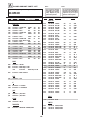
Diagnostic Item
Description
* Power does not turn on
No. of times
STANDBY/TIMER
lamp flashes
Self-diagnostic display/
Diagnostic result
Does not light
Probable Cause
Location
Detected Symptoms
* Power cord is not plugged in.
* Power does not come on.
* Fuse is burned out (F601)
* No power is suppled to the TV.
* AC power supply is faulty.
* +B overcurrent (OCP)
2 times
2:0 or 2:1
* H.OUT (Q502) is shorted. (A board)
* Power does not come on.
* IC751 (for 13"), IC701 and
* Load on power line is shorted.
Q701 ( for 20"/21") is shorted. (C board)
* Vertical deflection stopped
4 times
4:0 or 4:1
* +13V is not supplied. (A board)
* Has entered standby state after horizontal raster.
* IC 541 is faulty (A board)
* Vertical deflection pulse is stopped.
* Power line is shorted or power supply is stopped.
* White balance failure
(not balanced)
5 times
5:0 or 5:1
* Video OUT (Q394 to 392) is faulty. (A board) * No raster is generated.
* IC301 is faulty. (A board)
* G2 is improperly adjusted. (Note 2)
Note 1: If a +B overcurrent is detected, stoppage of the vertical deflection is detected simultaneously.
The symptom that is diagnosed first by the microcontroller is displayed on the screen.
Note 2: Refer to Screen (G2) Adjustment in Section 3-4 of this manual.
—4—
* CRT cathode current detection reference pulse
output is small.
KV-[13M40/50/51], KV-[14MB40/40C/40A], KV-[20M40/S40/S41/V80], KV-[21SE40/40A/40C/80/80A/80C],
KV-[21MB40C/40M/40P], KV-[21ME40/40P], KV-[21SB40/40M/40P], KV-21XT4A
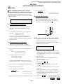
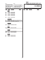
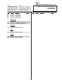
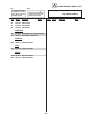
DISPLAY OF STANDBY/TIMER LIGHT FLASH COUNT
2 times
4 times
5 times
Lamp ON 0.3 sec.
Lamp OFF 0.3 sec.
Lamp OFF
3 sec.
STANDBY/SLEEP lamp
Diagnostic Item
Flash Count*
+B overcurrent
2 times
Vertical deflection stopped 4 times
White balance failure
5 times
* One flash count is not used for self-diagnostic.
STOPPING THE STANDBY/TIMER FLASH
Turn off the power switch on the TV main unit or unplug the power cord from the outlet to stop the STANDBY/TIMER lamp from flashing.
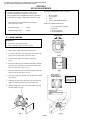
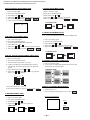
SELF-DIAGNOSTIC SCREEN DISPLAY
For errors with symptoms such as "power sometimes shuts off" or "screen sometimes goes out" that cannot be confirmed, it is pos sible to bring up
past occurances of failure for confirmation on the screen:
[To Bring Up Screen Test]
In standby mode, press buttons on the remote commander sequentially in rapid succession as shown below:
Screen display
channel 5
Sound volume –
Power ON
Note that this differs from entering the service mode (sound volume + ).
Self-Diagnostic screen display
SELF DIAGNOSTIC
2:
3:
4:
5:
101:
N/A
N/A
0 <-------------Numeral "0" means that no fault has been detected.
0
0
1 <-------------Numeral "1" means a fault has been detected one time only.
0
HANDLING OF SELF-DIAGNOSTIC SCREEN DISPLAY
Since the diagnostic results displayed on the screen are not automatically cleared, always check the self-diagnostic screen during repairs. When
you have completed the repairs, clear the result display to "0".
Unless the result display is cleared to "0", the self-diagnostic function will not be able to detect subsequent faults after completion of the repairs.
[Clearing the result display]
To clear the result display to "0", press buttons on the remote commander sequentially as shown below when the diagnostic screen is being
displayed.
Channel 8
ENTER
[Quitting Self-diagnostic screen]
To quit the entire self-diagnostic screen, turn off the power switch on the remote commander or the main unit.
—5—
KV-[13M40/50/51], KV-[14MB40/40C/40A], KV-[20M40/S40/S41/V80], KV-[21SE40/40A/40C/80/80A/80C],
KV-[21MB40C/40M/40P], KV-[21ME40/40P], KV-[21SB40/40M/40P], KV-21XT4A
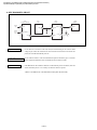
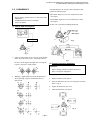
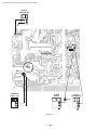
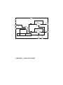
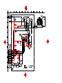
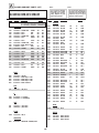
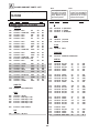
6. SELF-DIAGNOSTIC CIRCUIT
IC301
Y/CHROMA JUNGLE
FROM
CRT
21
IC541
V.OUT
IO-BDAT
IK IN
REF
FROM
IC521
PIN 7
IC001
SYSTEM
3
IC003
MEMORY
36
5
B-DAT
17 I-PROT
18 HP/PROTECT
SDA
+B overcurrent (OCP)
37
35
SDAT
O-LED
18
Occurs when an overcurrent on the +B(115V) line is detected by pin 18 of IC301. If the
voltage to pin 18 of IC301 is less than 1V when V.SYNC is more than seven verticals in a
period, the unit will automatically turn off.
Vertical deflection stopped
Occurs when an absence of the vertical deflection pulse is detected by pin 17 of IC001.
Power supply will shut down when waveform interval exceeds 2 seconds.
White balance failure
If the RGB levels* do not balance within 2 seconds after the power is turned on, this error
will be detected by IC301. TV will stay on, but there will be no picture.
*(Refers to the RGB levels of the AKB detection Ref pulse that detects IK.)
—6—
KV-[13M40/50/51], KV-[14MB40/40C/40A], KV-[20M40/S40/S41/V80], KV-[21SE40/40A/40C/80/80A/80C],
KV-[21MB40C/40M/40P], KV-[21ME40/40P], KV-[21SB40/40M/40P], KV-21XT4A
SAFETY CHECK-OUT
After correcting the original service problem, perform the
following safety checks before releasing the set to the
customer:
1. Check the area of your repair for unsoldered or poorlysoldered connections. Check the entire board surface
for solder splashes and bridges.
2. Check the interboard wiring to ensure that no wires
are “pinched” or contact high-wattage resistors.
3. Check that all control knobs, shields, covers, ground
straps, and mounting hardware have been replaced.
Be absolutely certain that you have replaced all the
insulators.
4. Look for unauthorized replacement parts, particularly
transistors, that were installed during a previous
repair. Point them out to the customer and
recommend their replacement.
5. Look for parts which, though functioning, show
obvious signs of deterioration. Point them out to
the customer and recommend their replacement.
6. Check the line cords for cracks and abrasion.
Recommend the replacement of any such line cord
to the customer.
7. Check the B+ and HV to see if they are specified
values. Make sure your instruments are accurate;
be suspicious of your HV meter if sets always have
low HV.
8. Check the antenna terminals, metal trim, “metallized"
knobs, screws, and all other exposed metal parts for
AC Leakage. Check leakage as described below.
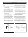
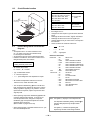
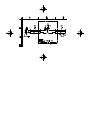
LEAKAGE TEST
The AC leakage from any exposed metal part to earth ground
and from all exposed metal parts to any exposed metal part having
a return to chassis, must not exceed 0.5 mA (500 microampere).
Leakage current can be measured by any one of three methods.
1. A commercial leakage tester, such as the Simpson 229 or
RCA WT-540A. Follow the manufacturers' instructions to
use these instructions.
2. A battery-operated AC milliammeter. The Data Precision
245 digital multimeter is suitable for this job.
3. Measuring the voltage drop across a resistor by means of
a VOM or battery-operated AC voltmeter. The "limit"
indication is 0.75 V, so analog meters must have an accurate
low voltage scale. The Simpson's 250 and Sanwa
SH-63Trd are examples of passive VOMs that are suitable.
Nearly all battery operated digital multimeters that have a
2V AC range are suitable. (See Fig. A)
HOW TO FIND A GOOD EARTH GROUND
A cold-water pipe is guaranteed earth ground; the cover-plate
retaining screw on most AC outlet boxes is also at earth ground.
If the retaining screw is to be used as your earth-ground, verify
that it is at ground by measuring the resistance between it and a
cold-water pipe with an ohmmeter. The reading should be zero
ohms. If a cold-water pipe is not accessible, connect a 60-l00 watts
trouble light (not a neon lamp) between the hot side of the receptacle and the retaining screw. Try both slots, if necessary, to
locate the hot side of the line, the lamp should light at normal
brilliance if the screw is at ground potential. (See Fig. B)
To Exposed Metal
Parts on Set
0.15 µF
1.5 k W
AC
Voltmeter
(0.75 V)
Earth Ground
Fig. A. Using an AC voltmeter to check AC leakage.
—7—
The instructions mentioned in this section are partial abstracts from the Operating Instruction Manual. The pages numbers shown reflect those of the Operating Instruction Manual.
—8—
This symbol is intended
to alert the user to the
presence of uninsulated
“dangerous voltage” within the
product’s enclosure that may
be of sufficient magnitude to
constitute a risk of electric
shock to persons.
This symbol is
intended to alert the
user to the presence
of important operating
and maintenance (servicing)
instructions in the literature
accompanying the appliance.
CAUTION
When using TV games,
computers, and similar
products with your TV, keep
the brightness and contrast
functions at low settings. If
a fixed (non-moving) pattern
is left on the screen for long
periods of time at a high
brightness or contrast setting,
the image can be permanently
imprinted onto the screen.
Continuously watching the
same channel can cause the
imprint of station logos onto
the TV screen. These types of
imprints are not covered by
your warranty because they are
the result of misuse.
You are cautioned that any
changes or modifications
not expressly approved in
this manual could void
your authority to operate
this equipment.
Safety Precautions
• Operate the TV only on 120
V AC.
• One blade of the power
plug is wider than the other
for safety purposes and will
fit into the power outlet only
one way. If you are unable to
insert the plug fully into the
outlet, contact your dealer.
TO PREVENT ELECTRIC
SHOCK, DO NOT USE THIS
POLARIZED AC PLUG
UNLESS THE BLADES CAN
BE FULLY INSERTED TO
PREVENT BLADE
EXPOSURE.
2
• If any liquid or solid object
falls into the TV, unplug it
and have it checked by
qualified personnel before
operating it further.
• Unplug the TV from the
wall outlet if you are not
going to use it for several
days or more. To disconnect
the cord, pull it out by the
plug. Never pull the cord
itself.
For more safety information,
see the “IMPORTANT
SAFEGUARDS” leaflet packed
with your TV.
Protecting the TV
• To prevent internal heat
build-up, do not block the
ventilation openings.
• Do not install the TV in a
hot or humid place, or in a
place subject to excessive
dust or mechanical
vibration.
Note on CAPTION VISION
This television receiver
provides display of television
closed captioning in
accordance with § 15.119 of the
FCC rules.
Note to CATV System Installer
Article 820-40 of the NEC that
provides guidelines for proper
grounding and, in particular,
specifies that the cable ground
shall be connected to the
grounding system of the
building, as close to the point
of cable entry as practical.
Use of this television for other
than private viewing of
programs broadcast on UHF
or VHF or transmitted by cable
companies for the use of the
general public may require
authorization from the
broadcaster/cable company
and/or program owner.
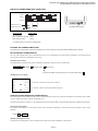
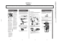
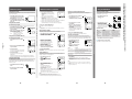
Connecting an Indoor, Outdoor or Cable Antenna
This connection offers the best picture quality. Connection
is made directly from the cable or antenna to the TV.
A
75-ohm coaxial cable
VHF only
or
VHF/UHF
or
Cable
VHF/UHF
If you cannot connect your antenna or cable directly to the
TV antenna terminal, follow one of the diagrams below.
B
VHF only
or
UHF only
or
VHF/UHF
300-ohm twin lead cable
VHF/UHF
Antenna connector
(Supplied for KV-13M40, 13M50, 13M51 only)
75-ohm coaxial cable
C
VHF
and
VHF/UHF
EAC-66 U/V
mixer
(not supplied)
UHF
300-ohm twin lead cable
Connecting to a Cable TV System Through a
Cable Box
Some pay cable TV systems use scrambled or encoded
signals that require a cable box* to view all channels.
Cable
VHF/UHF
Step 2: Using the Remote Control
Connecting a VCR
Inserting Batteries
See your VCR instructions to set up the VCR. After connecting
the VCR to the TV, you will be able to do the following:
• Watch video tapes
• Record one TV program while viewing another
Insert two size AA (R6) batteries (supplied) by matching the
+ and – on the batteries to the + and – inside the battery
compartment. With normal use, the batteries should last for
approximately six months.
Notes
• If your cable system requires the use of a cable box, install it
between the cable and the VCR.
• For a monaural VCR, connect the audio output of the VCR to the
AUDIO L (MONO) on the TV.
Cable Box
Antenna/
Cable
Antenna/
Cable
VHF/UHF OUT
AUDIO-R AUDIO-L VIDEO
AUDIO
(black)
VIDEO 1 IN
R-AUDIO-L(MONO)
S-VIDEO
VIDEO
AUDIO
(black)
3
VIDEO
(yellow)
R
Notes
• Remove the batteries to avoid possible damage from battery leakage
if you will not be using the remote control for an extended period of
time.
• Handle the remote control with care. Avoid dropping it, getting it
wet, or placing it in direct sunlight, near a heater, or where the
humidity is high.
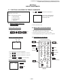
Remote Control Operation Buttons
AUDIO OUT
For models
with mono
inputs
(KV-13M40,
13M50, 13M51,
20M40)
L
VIDEO
(yellow)
In the instructions that follow, please refer to the buttons on
your remote control. The remote control shown is model
RM-Y155.
Video Cable (not supplied)
MUTING
POWER
SLEEP
AUDIO-R AUDIO-L VIDEO
(red) (white) (yellow)
AUDIO-R AUDIO-L VIDEO
(red) (white) (yellow)
Video Cable (not supplied)
For models
with stereo
inputs
(KV-20S40,
20S41)
MUTING (page 9)
SLEEP (page 10)
MTS (page 14)
(RM-Y155 only)
TV (POWER)
MTS
TV/VIDEO (page 9)
DISPLAY (page 9)
0–9 buttons
Connecting a Camcorder
JUMP
ENTER
JUMP (page 9)
All models except KV-13M40
Use this connection to view a video tape from a camcorder.
ENTER
MENU
> or . select
buttons
MENU
RESET
(Front AV Panel)
SELECT
RESET (page 12, 13)
SELECT
VOL
VIDEO
(yellow)
CH
L(MONO)-AUDIO-R
To audio
outputs
VIDEO 2 INPUT
*Cable box
S-VIDEO
LINE OUT
OUT
Note
• If you will be controlling all channel selection through your
cable box, you should consider using the CHANNEL FIX
feature discussed on page 11.
VCR
TV
VHF/UHF
VIDEO
IN
VHF/UHF IN
CH +/–
VOLUME
AUDIO R (red)
AUDIO L (white)
RM-Y155
To video
output
Cable (not supplied)
TV
Notes
• For a monaural camcorder, connect the audio output of the
camcorder to AUDIO L (MONO) on the TV.
• If you are connecting your camcorder to a monaural TV
(KV-13M50, 13M51, 20M40 only), plug the white audio connector
into the AUDIO-L input on the TV.
• You can also connect a camcorder to inputs on the rear of the TV
(all models).
4
5
Model number
Connecting a VCR • Connecting a Camcorder • Using the Remote Control • Inserting Batteries • Remote Control Operation Buttons
To prevent fire or shock
hazard, do not expose the TV
to rain or moisture.
Step 1: Connecting the TV
The following steps guide you through your initial set up.
Check the model number of your TV (located on the front
of this manual) and select the appropriate diagram.
Warnings and Cautions • Connecting the TV • Connecting an Antenna • Connecting a Cable Box
Warnings and Cautions
KV-[13M40/50/51], KV-[14MB40/40C/40A], KV-[20M40/S40/S41/V80], KV-[21SE40/40A/40C/80/80A/80C],
KV-[21MB40C/40M/40P], KV-[21ME40/40P], KV-[21SB40/40M/40P], KV-21XT4A
SECTION 1-1
GENERAL
Changing the Menu Language
Setting Up the TV Automatically
Except Canadian models
The menu illustrations are for KV-20S40. Your on-screen menus
may not look like those used within this manual. When a feature is
only available to a limited set of models, those models will be
listed.
KV-20M40, 20S40, 20S41 only
The Easy Set Up Guide allows you to set up the on-screen language
and set all receivable channels. (The Easy Set Up Guide screen
appears every time you turn on the TV until you perform AUTO
PROGRAM).
1 Press POWER to turn on your TV.
The Easy Set Up Guide screen
appears.
2 (Except Canadian Models) Press
CH + to select English screens or
CH – to select Spanish screens.
3 Press VOL + to continue or VOL –
for a DEMO of functions and menus.
If you want to view the menus in Spanish, you can change the
menu language.
1 Press MENU.
The main menu appears.
Move the cursor V or v to the
SET UP
menu, press SELECT.
ENGLISH:
[CH+]
ESPANOL:
[CH-]
AUTO SET UP: [VOL+]
DEMO:
[VOL-] First please connect
cable/antenna.
Press [SETUP]to exit
2 Press V or v to move
the cursor to LANGUAGE
and press SELECT.
ENGLISH will appear red.
V
v
Ł
SET UP
CHANNEL SET UPŁ
FAVORITE CHANNELŁ
CHANNEL BLOCKŁ
CAPTION VISION:CC1
LANGUAGE: ENGLISHŁ
MENU
Ł
To perform this function again
Press the SET UP button on your TV.
Auto Programming Your Channels (AUTO PROGRAM)
Move
3 Press V or v to select
ESPAÑOL and
press SELECT.
ESPAÑOL will turn
red and the menu will
appear in Spanish.
4 Press MENU to return to the TV program.
Select
Exit
MENU
PREFERENCIAS
AJUSTE DE CANAL
CANAL FAVORITO Ł
BLOQUEAR CANALŁ
CAPTION VISION:CC1
LENGUAJE: ESPANOL
MENU
Mover
Seleccionar
Salir MENU
The AUTO PROGRAM feature allows you to set all receivable
channels in one step. After this function is completed, you may
delete unwanted channels or add additional channels.
Notes
• If the TV is set to VIDEO, you cannot run AUTO PROGRAM. Press
TV/VIDEO on the remote control until a channel number appears.
• It is usually best to preset channels during the day when more channels
are broadcasting and receivable.
MENU
1 Press MENU.
SET UP
CHANNEL SET UPŁ
FAVORITE CHANNELŁ
CHANNEL BLOCKŁ
CAPTION VISION:CC1
LANGUAGE: ENGLISHŁ
MENU
—9—
3 Move the cursor V or v to
CHANNEL SET UP and press
SELECT.
4 Move the cursor V or v to
AUTO PROGRAM and press
SELECT.
AUTO PROGRAM appears on
the screen and the TV starts
scanning and presetting channels.
Move
Select
Exit
MENU
Skipping or Adding Channels (CHANNEL SKIP /ADD)
Press POWER to turn the TV on.
After you run AUTO PROGRAM, you can skip unnecessary channels or
add new ones.
Selecting a Channel Directly
1 Press MENU and select the SET UP
menu.
2 Move the cursor to CHANNEL SET UP
and press SELECT.
3 Press V or v to CHANNEL SKIP/ADD
and press SELECT.
Press 0–9 to select a channel.
The channel changes after 2 seconds, or
you can press ENTER for immediate selection.
CHANNEL SET UP
Ł
CABLE: OFFŁ
CHANNEL FIX: OFF
AUTO PROGRAM
CHANNEL SKIP/ADDŁ
MENU
Move
Select
Exit
Notes
• Pressing any button on the remote control while AUTO PROGRAM is
scanning and presetting channels will cause AUTO PROGRAM to stop.
• When you run AUTO PROGRAM your CHANNEL FIX and ON/OFF
TIMER settings will be erased.
MENU
5
7
8
Move
4 To skip or add a channel:
(1) Press CH +/– or 0–9 to enter
the desired channel.
(2) Press SELECT to SKIP or ADD.
Select
Exit
MENU
9
CH
33
Note
• Keeping the CH + or – button pressed, allows
you to rapidly scan to the desired channel.
SKIPŁ
Ł
Use[0-9]or[CH+/-]
to select the channel
Jumping Quickly Between Two Channels
Move
Select
Exit
MENU
Press JUMP.
The TV alternates or jumps between the
last two channels viewed.
Note
• If a channel you want to add was not received by AUTO PROGRAM, you
must use the 0-9 buttons to manually add the channel.
JUMP
Note
• You can only jump to channels you have selected
with the 0–9 keys.
Setting Cable TV On or Off (CABLE)
Muting the Sound
If you have connected the TV to a cable TV system, set CABLE to ON. If
you will be using an antenna, set CABLE to OFF to receive VHF/UHF
channels.
SET UP
CHANNEL SET UPŁ
FAVORITE CHANNELŁ
CHANNEL BLOCKŁ
CAPTION VISION:CC1
LANGUAGE: ENGLISHŁ
MENU
Move
4 Move the cursor to CABLE and press
SELECT.
5 Press V or v to select ON or OFF.
6 Press SELECT.
7 Press MENU to return to the TV program.
6
Scanning Channels
Press CH +/– until the channel appears.
CHANNEL SKIP/ADDŁ
5 To skip or add other channels,
repeat step 4.
6 Press MENU to return to the TV program.
1 Press MENU.
2 Move the cursor to the SET UP
menu
and press SELECT.
3 Move the cursor to CHANNEL SET UP
and press SELECT.
3
0
Select
Exit
MENU
CHANNEL SET UPŁ
Ł
CABLE: OFFŁ
CHANNEL FIX: OFFŁ
AUTO PROGRAM
CHANNEL SKIP/ADDŁ
MENU
Move
2
4
Select
Exit
MENU
After adjusting the CABLE setting, you will
need to run AUTO PROGRAM. (See page 7).
CABLE: OFFŁ
CHANNEL FIX: OFFŁ
AUTO PROGRAM
CHANNEL SKIP/ADDŁ
MENU
1
ENTER
CHANNEL SET UPŁ
Ł
Note
• If VIDEO is on the screen, press TV/VIDEO until a channel number appears.
Note
• If no picture appears, the TV may be set to a video input and CABLE can not
be selected. Press TV/VIDEO until a channel number appears, then follow
steps 1–6.
Press MUTING.
MUTING appears on the screen.
To restore the sound, press MUTING again,
or press VOL +.
MUTING
Displaying On-Screen Information
Use the DISPLAY key to check current time, channel and Multichannel TV
Sound (MTS).
1 Press DISPLAY.
The channel number and local time (if set), are displayed. The TV
displays the MTS mode if SAP or STEREO are selected and available
(KV-20S40, 20S41 only).
The MTS mode display disappears after 4 seconds.
2 Press DISPLAY again.
CC1 (default setting) appears on the screen for a few seconds. A
printed version of the dialog and sound effects will appear, if
available.
3 To turn off CAPTION VISION, press DISPLAY again until DISPLAY
OFF appears.
It will take a few seconds for DISPLAY OFF to disappear.
Notes
• See page 12 for more information about CAPTION VISION.
• See page 14 for more information about MTS.
Watching Video Tapes
1 Press TV/VIDEO until the correct
video input appears.
TV/ VIDEO
2 Press PLAY on your VCR to view the video tape.
3 Press TV/VIDEO to return to the TV program.
Listening with Headphones or an Earphone
Plug the headphones or earphone into the jack on the front of the TV.
Using headphones will turn off the sound to the TV speakers.
Note
• If your TV is monaural, the monaural sound will be heard from both
headphones.
6
7
8
9
KV-[13M40/50/51], KV-[14MB40/40C/40A], KV-[20M40/S40/S41/V80], KV-[21SE40/40A/40C/80/80A/80C],
KV-[21MB40C/40M/40P], KV-[21ME40/40P], KV-[21SB40/40M/40P], KV-21XT4A
2 Move the cursor V or v to
the SET UP
menu and
press SELECT.
The SET UP menu appears.
Watching the TV
Channel SKIP/ADD • CABLE • Watching the TV • Selecting • Scanning • JUMP • Muting • On-Screen Information • Watching Video Tapes • Headphones
Step 4: Setting up Your Channels
Setting the Menu Language • Setting up Your Channels • Easy Set Up • Auto Programming
Step 3: Setting Menu Language
Setting DAYLIGHT SAVING
All models except KV-13M40
You can program DAYLIGHT SAVING to automatically adjust the time.
1 Press MENU and select the TIMER menu.
2 Move the cursor to DAYLIGHT SAVING
and press SELECT.
3 Press V or v to select YES or NO based
on the following options:
Spring: Select YES, the current time
moves one hour ahead.
Fall:
Select NO, the current time
moves back one hour.
TIMER
DAYLIGHT SAVING:YESŁ
CURRENT TIME SET
ON/OFF TIMERŁ
MENU
SUN 10:02 AM
Select
Exit
Move
MENU
Setting the clock (CURRENT TIME SET)
All models except KV-13M40
1 Press MENU and select the TIMER
menu.
TIMER
DAYLIGHT SAVING:YESŁ
CURRENT TIME SET
ON/OFF TIMERŁ
MENU
— 10 —
SUN 10:02 AM
Select
Exit
Move
2 Move the cursor to CURRENT TIME SET
and press SELECT.
MENU
CURRENT TIME SET
Ł
SUN 10:0_ AM
MENU MENU
c Press V or v to set the duration, up to six hours, and press SELECT.
d Press V or v to select the channel and press SELECT.
The TIMER indicator, on the front of the TV, will light up.
To erase your ON/OFF TIMER settings
Press RESET, while in the TIMER menu.
Note
• If you exit the ON/OFF TIMER menu while setting the TIMER, your settings
will be saved.
Setting FAVORITE CHANNEL
This feature provides quick access to your favorite channels.
1 Press MENU and select the SET UP
2 Move the cursor to FAVORITE
CHANNEL and press SELECT.
SET UP
CHANNEL SET UPŁ
FAVORITE CHANNELŁ
CHANNEL BLOCKŁ
CAPTION VISION:CC1
LANGUAGE: ENGLISHŁ
MENU
Move
Select
Exit
Select
Exit
MENU
3 Set the current day.
Press SELECT and press V or v until the
day entry is highlighted, press SELECT.
Ł
Ł
Set the time
Move
Select
Exit
MENU
Setting the ON/OFF TIMER
All models except KV-13M40
You can program your TV for scheduled viewing using the ON/OFF
TIMER. The CURRENT TIME SET must be set in order for the ON/OFF
TIMER to function.
Move
Select
10
Exit
MENU
Move
Select
Exit
MENU
3 Move the cursor to 1 or 2 and
press SELECT.
4 Press V or v until you reach the
channel you want to block and
press SELECT.
When you try to tune to the blocked
channel, BLOCKED will appear on
the screen. CAPTION VISION will
also be blocked.
CHANNEL BLOCK
Ł
1. CH 22
2. CH___Ł
MENU
Select a position
Move
Select
Exit
MENU
Selecting CAPTION VISION
Some programs are broadcast with CAPTION VISION. These
services are sometimes limited to specific broadcasting networks
and may not be available in your area. (CC1 is the default setting).
1 Press MENU and select the
SET UP
menu.
2 Move the cursor V or v to
CAPTION VISION and press
SELECT.
3 Press V or v and set your TV
to one of the following
options:
Choose
SET UP
CHANNEL SET UPŁ
FAVORITE CHANNELŁ
CHANNEL BLOCKŁ
CAPTION VISION:CC1
LANGUAGE: ENGLISHŁ
MENU
Move
Select
Exit
MENU
To Display
A printed version of the dialog or sound effects of
a program. (The default setting is CC1).
Station/network related information that usually
is not related to the program.
This feature is useful when you want to control all channel selection
through a cable box or video equipment.
XDS (Extended
Data Services)
A program’s type, name, length and call letters.
1 Press MENU and select the
SET UP
menu.
2 Move the cursor V or v to
CHANNEL SET UP and press
SELECT.
4 Press DISPLAY.
The caption will appear in a few seconds, if available.
5 To turn off CAPTION VISION, press DISPLAY until DISPLAY
OFF appears.
SET UP
CHANNEL SET UPŁ
FAVORITE CHANNELŁ
CHANNEL BLOCKŁ
CAPTION VISION:CC1
LANGUAGE: ENGLISHŁ
MENU
Using the VIDEO Menu
Adjusting the VIDEO Settings
You can adjust the PICTURE, BRIGHTNESS, COLOR, HUE, and
SHARPNESS of any TV image.
1 Press MENU and select the
VIDEO
menu.
Select
Exit
CHANNEL SET UP
3 Select CHANNEL FIX and set your
Ł
CABLE: OFF
TV to one of the following
CHANNEL FIX: 2
options:
AUTO PROGRAM
CHANNEL SKIP/ADD
2–6: When the cable box is
MENU
connected to VHF/UHF input.
Use your cable box remote to
Move
Select
Exit
change channels.
VIDEO 1: When you have connected video equipment (e.g. DSS
receiver) and you want the TV fixed to it. You will be able to
alternate between video sources.
OFF: When you want to switch CHANNEL FIX off.
MENU
Move
2 Move the cursor V or v to
the feature you want to
adjust and press SELECT.
See the ADJUSTABLE ITEMS
chart below for a list of the
adjustments you can make.
Ł
Exit
MENU
Ł
Exit
MENU
Move
Select
Item
Press V to
Press v to
PICTURE
BRIGHTNESS
Increase the contrast
Brighten the picture
Decrease the contrast
Darken the picture
COLOR
Increase color intensity
Decrease color intensity
HUE
Increase the green tones
Decrease the green tones
SHARPNESS
Sharpen the picture
Soften the picture
3 Press MENU to return to the TV program.
Restoring the factory video settings
Press RESET, while in the VIDEO menu.
Notes
• Captions disappear for a few seconds when you press the MUTING
button.
• Captions may appear with a white box or other errors, if you have poor
reception on the channel.
MENU
12
V
v
Select
VIDEO
PICTURE
Ł
BRIGHTNESS COLOR
Ł
HUE
SHARPNESS MENU
ADJUSTABLE ITEMS
Notes
• For information on connecting a cable box, see page 3.
• ON/OFF TIMER settings will be erased when CHANNEL FIX is set.
• FAVORITE CHANNEL can not be accessed when CHANNEL FIX is set.
11
VIDEO
PICTURE
Ł
BRIGHTNESS COLOR
Ł
HUE
SHARPNESS MENU
SET UP
CHANNEL SET UPŁ
FAVORITE CHANNELŁ
CHANNEL BLOCKŁ
CAPTION VISION:CC1
LANGUAGE: ENGLISHŁ
MENU
TEXT 1, 2, 3 or 4
Move
TIMER
DAYLIGHT SAVING:YESŁ
CURRENT TIME SET
ON/OFF TIMERŁ
MENU
menu.
CC1, 2, 3 or 4
1 Press MENU and select the TIMER
menu.
2 Move the cursor to ON/OFF TIMER
and press SELECT.
To use FAVORITE CHANNEL
Press SELECT when in normal viewing mode. Your options will appear
on the screen.
Setting CHANNEL FIX
4 Set the current time.
Press SELECT until the time entry is
highlighted.
Press V or v until the current hour is displayed and press SELECT.
Press V or v until the current minute is displayed and press SELECT.
1 Press MENU and select the SET UP
2 Move the cursor V or v to
CHANNEL BLOCK and press SELECT.
MENU
FAVORITE CHANNEL
MODE: MANUALŁ
1. 10Ł
2. ___
3. ___
4. ___
5. ___
MENU Move
This feature is useful in preventing child access to designated
channels.
To erase your CHANNEL BLOCK settings
Press RESET, while in the CHANNEL BLOCK menu.
menu.
3 Press V or v to select AUTO or
MANUAL and press SELECT.
Selecting AUTO will display the
last five channels chosen with the
remote control’s 0–9 buttons.
4 Press V or v to select 1, 2, 3, 4 or
5 and press SELECT.
5 Press V or v to highlight the
desired channel and press SELECT.
Blocking out a Channel (CHANNEL BLOCK)
13
KV-[13M40/50/51], KV-[14MB40/40C/40A], KV-[20M40/S40/S41/V80], KV-[21SE40/40A/40C/80/80A/80C],
KV-[21MB40C/40M/40P], KV-[21ME40/40P], KV-[21SB40/40M/40P], KV-21XT4A
1 Press SLEEP until the length of time
SLEEP
you want the TV to stay on appears.
SLEEP appears one minute before
the TV shuts off.
2 To cancel the sleep timer, press SLEEP
again until SLEEP OFF appears, or turn
off the TV.
Additional Features (continued)
ON/OFF TIMER
3 Enter the ON/OFF TIMER setting.
Ł
a Press SELECT until the day entry is
EVERY SUN - SATŁ
8:00 PM
2h CH10
highlighted.
MENU Ł
Press V or v to cycle through the day
Ł
options.
SUN
10:02 AM
Select an entry and press SELECT.
Move
Select
Exit
b Press SELECT until the time entry is
highlighted.
Press V or v to set the hour and press SELECT.
Press V or v to set the minute and press SELECT.
Additional Features (continued) • FAVORITE CHANNEL • CHANNEL FIX • CHANNEL BLOCK • CAPTION VISION
The SLEEP timer programs the TV to stay on for a length of time and then
shut off automatically.
Additional Features • SLEEP • DAYLIGHT SAVING • CURRENT TIME SET • ON/OFF TIMER
Additional Features
Setting the SLEEP Timer
Selecting Stereo or Bilingual Programs (MTS)
KV-20S40, 20S41 only
The Multichannel TV Sound (MTS) feature allows you to enjoy
Stereo Sound (STEREO), Second Audio Programs (SAP), or
Monaural Sound (MONO) when available.
1 Press MENU and select the AUDIO
2 Move the cursor to MTS and
press SELECT.
menu.
AUDIO
MTS: STEREO
MENU
Ł
Move
Select
Exit
3 Press V or v to select STEREO, SAP, or MONO and press
SELECT.
Choose
To
STEREO
Listen to stereo sound.
SAP
Listen to bilingual and other programs.
MONO
Reduce noise during poor stereo broadcasts.
For Direct MTS Access
Press MTS repeatedly to cycle through the MTS options.
Note
• If your TV does not have sound, try changing your MTS setting.
MENU
Video Menu • Video Setting • Audio Menu • Bilingual Programs (MTS)
Audio Menu
Troubleshooting
If you are having a problem with your TV, try the suggestions
below. If the problem persists, contact your nearest Sony
dealer.
Problem
No picture, no
sound
Suggestion
• Make sure the power cord is connected.
• If a red light keeps flashing on the front of your
TV, for more than a few minutes, call your local
service center.
• Check the TV/VIDEO setting: when watching
TV, set to TV; when watching video tapes, set
to VIDEO (page 9).
• Make sure the batteries have been inserted
correctly into the remote control.
• Try another channel. It could be station trouble.
Poor or no picture, • Adjust PICTURE in the VIDEO menu (page 13).
good sound
• Adjust BRIGHTNESS in the VIDEO menu
(page 13).
• Check the antenna and/or cable connections
(page 3).
• Press MUTING so that MUTING disappears
from the screen (page 9).
• Check your AUDIO settings. Your TV may be
set to SAP (page 14).
No color
• Adjust COLOR in the VIDEO menu (page 13).
• Make sure that a black and white program is
not being broadcast.
Only snow
appears on
the screen
• Check the CABLE setting in the SET UP menu
(page 8).
• Check the antenna and/or cable connections
(page 3).
• Make sure the channel selected is currently
broadcasting.
Dotted lines
or stripes
• Adjust the antenna.
• Move the TV away from other electronic
equipment. Some electronic equipment can
create electrical noise, which can interfere with
TV reception.
Double images
or ghosts
• Check your outdoor antenna or call your cable
service.
Cannot receive
higher number
channels (UHF)
when using an
antenna
• Make sure CABLE is set to OFF in the SET UP
menu (page 8).
• Use AUTO PROGRAM to add channels that
are not presently in the memory (page 7).
Cable stations
don’t seem to
work
• Make sure CABLE is set to ON in the SET UP
menu (page 8).
• Use AUTO PROGRAM to add channels that
are not presently in the memory (page 7).
Remote control
does not operate
• Batteries could be weak. Replace them (page 5).
• Move the TV 3–4 feet away from fluorescent
lights.
The TV needs
to be cleaned
• Clean the TV with a soft dry cloth. Never use
strong solvents such as thinner or benzine,
which might damage the finish of the cabinet.
The TV is fixed
to one channel
• Try turning CHANNEL FIX off (page 11).
• Use AUTO PROGRAM to add receivable
channels that are not presently in the TV
memory (page 7).
If, after reading these operating instructions, you have additional
questions related to the use of your Sony television, please call our
Direct Response Center at 1-800-222-SONY (7669).
14
15
KV-[13M40/50/51], KV-[14MB40/40C/40A], KV-[20M40/S40/S41/V80], KV-[21SE40/40A/40C/80/80A/80C],
KV-[21MB40C/40M/40P], KV-[21ME40/40P], KV-[21SB40/40M/40P], KV-21XT4A
— 11 —
Good picture,
no sound
Las instrucciones contenidas en esta seccion, son abstractos del manual de instrucciones y operacion. La numeracion de las paginas hacen referencia el numero de pagina en el manual original.
— 12 —
Este símbolo sirve para
indicar al usuario la
presencia de altas
tensiones sin aislar en el interior
de este producto, las que pueden
ser de una magnitud que
presente riesgo de descargas
eléctricas.
Este símbolo sirve para
indicar al usuario que el
manual que acompaña a
este producto contiene
instrucciones importantes
referentes al funcionamiento y
mantenimiento del producto.
PRECAUCIÓN
Al utilizar videojuegos,
computadoras o productos
similares con el televisor,
mantenga los preferencias de
brillo y contraste a un nivel bajo.
Si una imagen fija permanece en
la pantalla durante mucho
tiempo con elevada intensidad
de brillo o contraste, la imagen
puede quedar grabada en la
pantalla de forma permanente.
Igualmente, ver continuamente
el mismo programa de televisión
podría dejar grabada en la
pantalla el logotipo de la
emisora. La garantía no cubre
estas quemaduras de la pantalla,
ya que se deben al mal uso del
aparato.
Cualquier cambio o
modificación que no se detalla
expresamente en el presente
manual podría anular su
autorización para emplear
este aparato.
Precauciones de seguridad
• Alimente el televisor
exclusivamente con 120␣ V CA
(con excepción KV-14MB40C,
21MB40C, 21ME40C, 21SB40C,
21SE40C).
• Alimente el televisor
exclusivamente con 220 V CA
(sólo KV-14MB40C, 21MB40C,
21ME40C, 21SB40C, 21SE40C).
• Por motivos de seguridad, un
contacto de la clavija del cable
eléctrico de este aparato es
más ancho que el otro y la
clavija entrará en el enchufe
en solamente una posición.
Si no puede introducirla
totalmente en el enchufe,
consulte con su concesionario.
PARA EVITAR DESCARGAS
ELÉCTRICAS, NO USE ESTA
CLAVIJA POLARIZADA A
MENOS QUE LOS
CONTACTOS QUEDEN
COMPLETAMENTE
DENTRO DEL ENCHUFE.
• Si algún líquido u objeto
cae dentro del televisor,
desenchufe el aparato y
llévelo a revisión por un
técnico calificado antes de
volver a utilizarlo.
• Si no va a utilizar el
televisor durante varios
días, desconéctelo. Para
desenchufar el cable eléctrico,
sujételo por la clavija, nunca
tire del cable mismo.
Para mayores informes
sobre medidas de seguridad,
consulte el folleto “NORMAS
IMPORTANTES SOBRE
SEGURIDAD” que acompaña al
televisor.
Protección del televisor
• Para evitar el
sobrecalentamiento interno,
no cubra las rejillas de
ventilación.
• No instale el televisor en un
lugar caliente o húmedo, ni
donde esté expuesto a
cantidades excesivas de polvo
o a vibraciones mecánicas.
Nota sobre CAPTION VISION
Este aparato de televisión
permite ver texto sobrepuesto
a las imágenes, en
cumplimiento con lo dispuesto
en el inciso 15.119 de las normas
de la Comisión Federal de
Comunicaciones (FCC) de EUA.
Nota para el técnico que instala
el sistema de cable
El inciso 820-40 de NEC
contiene normas para la puesta
a tierra y en particular, dispone
que la tierra del cable debe
conectarse al sistema de puesta
a tierra del edificio, en el punto
más cercano a la entrada del
cable como sea factible.
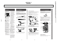
Conexión a Antena Interior, Exterior o de Cable
Utilice esta conexión para lograr una óptima calidad de imagen.
Se conecta el cable o la antena directamente al televisor.
A
Sólo VHF
o
VHF y UHF
o
Cable
Cable coaxial de 75 ohmios
VHF/UHF
Si no se puede conectar la antena o el cable directamente a la
terminal de antena del televisor, utilice las instrucciones de
la ilustración correspondiente.
Cable bifilar de 300 ohmios
B Sólo VHF
o
sólo UHF
o
VHF y UHF
VHF/UHF
Conector de antena (incluido)
C
Cable coaxial de 75 ohmios
VHF
y
VHF/UHF
Mezclador de
U/V EAC-66
(no incluido)
Conexión a Videograbadora
Instalación de las Pilas
Consulte las instrucciones para instalar la videograbadora. Una
vez conectada la videograbadora al televisor, podrá:
• Ver videocintas
• Grabar un programa de televisión mientras ve otro
Inserte dos pilas AA (R6) (se incluyen). Asegúrese que los signos
+ y – de las pilas concuerdan con los signos + y – dentro del
control remoto. Las pilas deben durar aproximadamente
6 meses con uso normal.
Notas
• Si su sistema de cable requiere de un decodificador, conéctelo entre el
cable y la videograbadora.
• Si utiliza una videograbadora monoaural, conecte la salida de audio de
la videograbadora al conector AUDIO L (MONO) del televisor.
Decodificador
Antena
o Cable
coaxial
Antena
o Cable
coaxial
VHF/UHF IN
Videograbadora
VHF/UHF OUT
LINE OUT
AUDIO-R AUDIO-L VIDEO
VHF/UHF
Televisor
VIDEO 1 IN
R-AUDIO-L(MONO)
AUDIO
(negro)
S-VIDEO
VIDEO
AUDIO
(negro)
VIDEO
(amarillo)
R
Notas
• Para evitar el daño que podría causar la fuga de electrólito de las pilas,
sáquelas del compartimiento si no piensa utilizar el control remoto
durante largo tiempo.
• Maneje el control remoto con cuidado. No lo deje caer ni permita que se
moje. No lo coloque bajo la luz solar directa, cerca de un calentador o en
lugares húmedos.
Operación de los Botones del Control Remoto
AUDIO OUT
L
VIDEO
(amarillo)
Cable de video (no se incluye)
Para modelos
con entradas
monoaural
(sólo KV-14MB40,
14MB40C, 21MB40C,
21MB40M, 21MB40P,
21ME40, 21ME40C)
Las siguientes instrucciones se refieren a los botones de su
control remoto. El dibujo corresponde al control remoto
RM-Y155.
MUTING
AUDIO-R
(rojo)
AUDIO-L
(blanco)
VIDEO
(amarillo)
AUDIO-R AUDIO-L VIDEO
(rojo) (blanco) (amarillo)
Para modelos
con entradas
estereofónicas
(sólo KV-21SB40C,
21SB40M, 21SB40P,
21SE40, 21SE40C)
Cable de video (no se incluye)
UHF
POWER
SLEEP
MUTING (pág. 9)
SLEEP(pág. 10)
MTS (pág. 14)
(sólo RM-Y155)
TV(POWER)
MTS
TV/VIDEO (pág. 9)
DISPLAY (pág. 9)
Botones de 0 a 9
Cable bifilar de 300 ohmios
Conexión a Sistema de Cable por Medio de
Decodificador.
Algunos sistemas de televisión por cable de paga usan
señales deformadas o codificadas que requieren un
decodificador* para poder ver todos los canales.
Cable
Conexión a Cámara de Video
JUMP
Con excepción KV-14MB40, 14MB40C
Utilice esta conexión para ver la videocinta de una cámara de
video.
JUMP (pág. 9)
ENTER
MENU
> o . botones
de seleccionar
MENU
RESET
VIDEO
SELECT
SELECT
VOL
CH
L(MONO)-AUDIO-R
CH +/–
VOLUMEN
VIDEO 2 INPUT
ENTRADA
ENTER
RESET (pág. 12 y 13)
(Parte delantera del televisor)
VHF/UHF
SALIDA
Salida de AUDIO-R (rojo)
Salida de AUDIO-L (blanco)
Salida de VIDEO (amarillo)
VIDEO (amarillo)
AUDIO-L (blanco)
AUDIO-R (rojo)
*Decodificador
RM-Y155
Nota
• Si va a hacer la selección de todos los canales a través de su
decodificador, debe usted considerar la posibilidad de usar la
función FIJAR CANAL, que se describe en la página 11.
Número de
modelo
TV
Cable (no se incluye)
El empleo de este televisor para
fines que no sean el de ver en
privado programas de televisión
de UHF, de VHF o transmitidos
por compañías de cable para uso
del público en general, puede
requerir la autorización de la
emisora o compañía de cable,
del propietario del programa o
de ambos.
2
Paso 2: Uso del Control Remoto
Notas
• Si utiliza una cámara de video monoaural, conecte la salida de audio de
la cámara al enchufe AUDIO L (MONO) del televisor.
• Si conecta su cámara de video a un televisor monoaural (sólo KV-14MB40,
14MB40C, 21MB40C, 21MB40M, 21MB40P, 21ME40, 21ME40C), enchufe
la clavija blanca de audio de la cámara en la entrada de AUDIO L del
televisor.
• También puede conectar su cámara de video a las entradas localizadas en
la parte posterior del televisor (todos los modelos).
Si pierde su control remoto
Con excepción KV-14MB40, 14MB40C
Usted puede usar los botones en la parte delantera del televisor
para controlar los menús y cambiar los canales.
3
4
5
Conexión a Videograbadora • Conexión a Cámara de Video • Uso del Control Remoto • Instalación de las Pilas • Operación de los Botones del Control Remoto
Para evitar el riesgo de incendios
o de descargas eléctricas, no
exponga al televisor a la lluvia ni
a la humedad.
Paso 1: Instalación
Este instructivo le guiará durante la instalación de su
televisor. Siga las indicaciones de los dibujos
correspondientes a su televisor (el número de modelo
aparece en la portada de este manual) y seleccione el
diagrama aproprado.
Advertencias • Instalación • Conexión a Antena • Conexión a Decodificador
Advertencias
KV-[13M40/50/51], KV-[14MB40/40C/40A], KV-[20M40/S40/S41/V80], KV-[21SE40/40A/40C/80/80A/80C],
KV-[21MB40C/40M/40P], KV-[21ME40/40P], KV-[21SB40/40M/40P], KV-21XT4A
SECTION 1-2
GENERAL
Programación Automática del Televisor
Las ilustraciones de los menús que se utilizan corresponden al
modelo KV-21SE40. Es posible que sus menús en pantalla no
aparezcan igual que aquellos utilizados en este manual. Al presentar
funciones que se encuentren en otros modelos, el manual indicará los
números de modelo correspondientes.
Con excepción KV-14MB40, 14MB40C
La función Guía de Programación Fácil le permitirá seleccionar el
idioma de los menús y sintonizar automáticamente todos los canales
que el televisor pueda recibir. (Mientras no lleve a cabo la AUTO
PROGRAMACIÓN, la pantalla que muestra la Guía de Programación
Fácil aparecerá cada vez que se encienda el televisor).
Si prefiere ver los menús en inglés, puede cambiar el idioma de los
menús.
1 Oprima POWER para encender
ENGLISH:
[CH+]
~
el televisor.
ESPANOL:
[CH-]
AUTO AJUSTE: [VOL+]
Aparecerá en pantalla la Guía de
DEMO:
[VOL-]Ł
MENU:
[TV/VIDEO]
Programación Fácil.
Ł
2 Oprima CH+ para que los menús
aparezcan en inglés o CH– para que
Oprima[SETUP]para salir
aparezcan en español.
3 Oprima VOL+ para continuar o VOL –
para una demostración de las funciones y menús.
1 Oprima MENU.
Aparece el menú
principal.
Coloque el cursor
V o v en el menú de
PREFERENCIAS
y oprima SELECT.
2 Oprima V o v para colocar
el cursor en LENGUAJE y
oprima SELECT.
La palabra ESPAÑOL
se pondrá roja.
V
v
Ł
PREFERENCIAS
AJUSTE DE CANAL
CANAL FAVORITOŁ
BLOQUEAR CANAL
CAPTION VISION:CC1
~
LENGUAJE: ESPANOLŁ
MENU
Ł
Mover
3 Oprima V o v para colocar
el cursor en ENGLISH y
oprima SELECT.
ENGLISH se pondrá roja y
los menús aparecerán en inglés.
Seleccionar
Salir
MENU
SET UP
CHANNEL SET UPŁ
FAVORITE CHANNELŁ
CHANNEL BLOCKŁ
CAPTION VISION:CC1
LANGUAGE: ENGLISHŁ
MENU
Move
Select
Exit
MENU
4 Para volver a la pantalla normal, oprima MENU.
Para repetir Auto Ajuste
Oprima SET UP en la parte delantera del televisor.
Programación Automática de los Canales (AUTO
PROGRAMACION)
La función de AUTO PROGRAMACION le permite programar en
un sólo paso todos los canales que su televisor pueda recibir.
Despues, podrá omitir los canales que no desee incluir o añadir
otros.
Notas
• Si el televisor está ajustado a una entrada de VIDEO, no podrá utilizar AUTO
PROGRAMACION. Oprima TV/VIDEO del control remoto hasta que
aparezca un número de canal.
• Se recomienda programar los canales durante el día, cuando es mayor el
número de canales que están transmitiendo.
1 Oprima MENU.
Nota
2 Coloque el cursor V o v en
el menú de PREFERENCIAS
y oprima SELECT o
.
Aparece el menú de
PREFERENCIAS.
PREFERENCIAS
AJUSTE DE CANAL
CANAL FAVORITOŁ
BLOQUEAR CANAL
CAPTION VISION:CC1
~
LENGUAJE: ESPANOLŁ
MENU
Mover
Seleccionar
Salir
MENU
3 Coloque el cursor V o v
en AJUSTE DE CANAL y
oprima SELECT.
4 Coloque el cursor V o v
en AUTO PROGRAMACION
y oprima SELECT.
En la pantalla aparece AUTO
PROGRAMACION y el televisor
empezará a buscar y programar
los canales automáticamente.
AJUSTE DE CANALŁ
Ł
CABLE: NOŁ
FIJAR CANAL: NOŁ
AUTO PROGRAMACION
~
OMITIR/ANADIR CANAL
MENU
Mover
Seleccionar
Salir
Oprima POWER para encender el televisor.
Después de efectuar la AUTO PROGRAMACION, podrá omitir los
canales no deseados o añadir otros.
Nota
• Si la indicación VIDEO aparece en la pantalla, oprima TV/VIDEO para que aparezca
un número de canal.
Selección Directa de Canales
1 Oprima MENU y seleccione el menú de PREFERENCIAS
.
AJUSTE DE CANALŁ
2 Coloque el cursor en AJUSTE DE CANAL
Ł
y oprima SELECT.
CABLE: NOŁ
FIJAR CANAL: SIŁ
3 Oprima V o v en OMITIR/AÑADIR CANAL
AUTO PROGRAMACION
~
OMITIR/ANADIR CANAL
y oprima SELECT.
Oprima los botones del 0 al 9 para
seleccionar un canal.
El canal cambiará en 2 segundos, o puede oprimir
ENTER después de haber seleccionado el canal para
un cambio inmediato.
MENU
Mover
Seleccionar
Salir
1
2
4
5
7
8
9
0
ENTER
MENU
3
6
Exploración de Canales
~
OMITIR/ANADIR CANALŁ
4 Para omitir o añadir un canal:
33
OMITIR
(1) Oprima CH +/– o del 0 al 9 para
MENU
seleccionar el canal que desea.
Use[0-9]o[CH+/-]para
seleccionar el canal
(2) Oprima SELECT para seleccionar
OMITIR o AÑADIR.
Mover
Seleccionar
Salir
5 Para omitir o añadir otros canales, repita
el paso 4.
6 Oprima MENU para volver al programa de televisión.
Oprima CH +/– hasta que aparezca el canal que desea.
CH
Nota
• Al mantener CH + o – oprimido, usted puede llegar
rápidamente al canal deseado.
MENU
Cambio Rápido Entre dos Canales
Nota
Oprima JUMP.
Oprima este botón para alternar entre dos canales.
• Si quiere añadir un canal que no se captó con AUTO PROGRAMACION, tendrá
que usar los botones de 0 a 9 para añadirlo.
Nota
• Podrá cambiar rápidamente sólo a un canal que haya seleccionado
con los botones del 0 al 9.
Para Activar o Desactivar el Sistema de Cable (CABLE)
Si conecta su televisor a un sistema de cable, cambie la función CABLE a
SI. Si utiliza una antena, cambie la función CABLE a NO para recibir
canales de VHF/UHF.
1 Oprima MENU.
2 Coloque el cursor en el menú de
PREFERENCIAS
y oprima SELECT.
3 Coloque el cursor en AJUSTE DE CANAL
y oprima SELECT.
PREFERENCIAS
AJUSTE DE CANAL
CANAL FAVORITOŁ
BLOQUEAR CANAL
CAPTION VISION:CC1
~
LENGUAJE: ESPANOLŁ
MENU
Mover
4 Coloque el cursor en CABLE y oprima
SELECT.
5 Oprima V o v para seleccionar SI o NO.
6 Oprima SELECT.
7 Oprima MENU para volver al
programa de televisión.
Seleccionar
Salir
MENU
AJUSTE DE CANALŁ
Ł
CABLE: NOŁ
FIJAR CANAL: NOŁ
AUTO PROGRAMACION
~
OMITIR/ANADIR CANAL
MENU
Mover
Seleccionar
Salir
JUMP
MENU
Después de ajustar la función de CABLE necesita efectuar la AUTO
PROGRAMACION. (Consulte pág. 7).
Nota
• Si la imagen no aparece, es posible que el televisor está ajustado a una entrada de
video y no se puede seleccionar CABLE. Oprima TV/VIDEO hasta que aparezca un
número de canal y repita los pasos del 1 al 6.
Eliminación del Sonido
Oprima MUTING.
En la pantalla aparece la indicación MUTING.
Para restablecer el sonido, vuelva a oprimir MUTING
u oprima VOL +.
MUTING
Información en Pantalla
Utilice el botón DISPLAY para ver la hora actual, canal y función de
sonido Multicanal (MTS).
1 Oprima DISPLAY.
Aparecerán el número de canal y la hora actual (si está ajustada).
También aparecerá la modalidad de sonido multicanal (MTS) que está
en uso si se ha seleccionado un segundo programa de audio (SAP)
o sonido estereofónico (ESTEREO) (Sólo KV-21SB40C, 21SB40M,
21SB40P, 21SE40, 21SE40C).
La indicación MTS desaparecerá a los 4 segundos.
2 Oprima DISPLAY una vez más.
CC1 (el ajuste de fábrica) aparecerá en la pantalla. Una versión escrita
del diálogo aparecerá, si la emisora ofrece este servicio.
3 Para desactivar CAPTION VISION, vuelva a oprimir DISPLAY hasta
que aparezca la indicación DISPLAY OFF.
DISPLAY OFF desparecerá a los tres segundos.
Notas
• Consulte la página 12 para mayores informes sobre CAPTION VISION.
• Consulte la página 14 para mayores informes sobre MTS.
MENU
Para ver Videocintas
Notas
• Si oprime cualquier botón del control remoto mientras AUTO
PROGRAMACION esté activada, esta función cesará.
• Al llevar cabo función AUTO PROGRAMACION, se borrarán sus selecciónes
de FIJAR CANAL y ENCENDIDO/APAGADO.
1 Oprima TV/VIDEO hasta que aparezca la entrada
de video que busca.
2 Para ver la cinta, oprima PLAY en su videograbadora.
3 Oprima TV/VIDEO para regresar a un programa
de televisión.
TV/ VIDEO
Uso de Auriculares
Introduzca la clavija de los auriculares en el enchufe ubicado en la parte
delantera del televisor. Al usar los auriculares, automáticamente se apagará
el sonido de las bocinas del televisor.
Nota
• Si su televisor es monoaural, escuchará el sonido monoaural en ambos auriculares.
6
7
8
9
KV-[13M40/50/51], KV-[14MB40/40C/40A], KV-[20M40/S40/S41/V80], KV-[21SE40/40A/40C/80/80A/80C],
KV-[21MB40C/40M/40P], KV-[21ME40/40P], KV-[21SB40/40M/40P], KV-21XT4A
— 13 —
• Con excepción de los modelos KV-14MB40, 14MB40C, usted puede controlar
los menús usando los botones en la parte delantera del televisor siguiendo las
instrucciones en la pantalla.
Para ver Programas de Televisión
Para Omitir o Añadir Canales (OMITIR/AÑADIR)
OMITIR/AÑADIR • CABLE • Para ver Programas • Selección de Canales • JUMP • Eliminación de Sonido • Información en Pantalla • Videocintas • Auriculares
Cambio de Idioma de los Menús
Ajuste de Idioma de los Menús • Programación de Canales • Guía de Programación Fácil • Programación Automática de Canales
Paso
Paso 4:
4: Programación
Programación de
de Canales
Canales
Paso 3: Ajuste de Idioma de los Menús
1 Oprima SLEEP hasta que aparezca el
SLEEP
número de minutos que desee.
Un minuto antes de que el televisor se
apague, aparecerá en la pantalla el
mensaje SLEEP.
2 Para cancelar el apagado automático,
vuelva a oprimir SLEEP hasta que
aparezca SLEEP OFF o apague el televisor.
Nota
• Si su televisor no recibe una señal en treinta minutos, se apagará automáticamente.
Para poner HORA DE VERANO
Puedes programar HORA DE VERANO para ajustar automáticamente el
tiempo.
1 Oprima MENU y seleccione el menú
.
de RELOJ
2 Coloque el cursor en HORA DE VERANO
y oprima SELECT.
3 Coloque V o v para seleccionar SI o NO
basandose en las siguientes opciones:
Primavera: Seleccione SI para adelantar
el reloj una hora.
Otoño:
Seleccione NO para atrasar el
reloj una hora.
RELOJ
HORA DE VERANO: SI
FIJAR HORA ACTUALŁ
ENCENDIDO/APAGADO
MENU
Mover
Seleccionar
Salir
MENU
Para poner el reloj a la hora (FIJAR HORA ACTUAL)
— 14 —
1 Oprima MENU y seleccione el menú
.
de RELOJ
RELOJ
HORA DE VERANO: SI
FIJAR HORA ACTUALŁ
ENCENDIDO/APAGADO
MENU
2 Coloque el cursor en FIJAR HORA ACTUAL
y oprima SELECT.
Mover
Seleccionar
Salir
MENU
FIJAR HORA ACTUAL
3 Indique el día.
DOM 10:0_ AM
MENUŁ Ł
Oprima SELECT hasta realzar el día.
Ł
Oprima V o v hasta que aparezca el día
Ł
de hoy y oprima SELECT.
4 Indique la hora.
Mover
Seleccionar
Salir
Oprima SELECT hasta realzar la hora.
Oprima V o v hasta que aparezca la hora actual y oprima SELECT.
Oprima V o v hasta que aparezca el minuto actual y oprima SELECT.
MENU
ENCENDIDO/APAGADO
3 Indique el día, hora, duración y canal
deseados.
CADA DOM - SAB
_8:00 Ł PM
2h CH10
a Oprima SELECT hasta realzar el renglón
MENUŁ Ł correspondiente a los días.
Ł
Oprima V o v para cambiar la opción del día.
Ł
DOM 10:02 AM
Cuando aparezca el día deseado,
Mover
Seleccionar
Salir
oprima SELECT.
b Oprima SELECT hasta realzar la hora.
Oprima V o v para indicar la hora deseada y oprima SELECT.
Oprima V o v para indicar el minuto deseado y oprima SELECT.
MENU
d Oprima V o v para indicar el canal deseado y oprima SELECT. Se
encenderá el indicador del reloj en la parte delantera del televisor.
Para borrar las indicaciones seleccionadas mediante ENCENDIDO/APAGADO
Oprima RESET mientras se encuentra en el menú de ENCENDIDO/APAGADO.
Nota
• Si se sale del menú de ENCENDIDO/APAGADO al estar programando esta
función, quedarán registradas las indicaciones seleccionadas.
Programación de CANAL FAVORITO
1 Oprima MENU y seleccione el menú de PREFERENCIAS
.
2 Coloque el cursor en CANAL FAVORITO
PREFERENCIAS
AJUSTE DE CANAL
y oprima SELECT.
CANAL FAVORITOŁ
BLOQUEAR CANAL
CAPTION VISION:CC1
~
LENGUAJE: ESPANOLŁ
MENU
BLOQUEAR CANAL
CAPTION VISION:CC1
~
LENGUAJE: ESPANOLŁ
MENU
Mover
Mover
3 Coloque el cursor para 1 o 2 y
oprima SELECT.
4 Oprima V o v para mostrar el canal
que desea bloquear y oprima SELECT.
Al escoger el canal que va a suprimir, la
palabra BLOQUEADO aparecerá en la
pantalla y se suprimirá CAPTION VISION.
Seleccionar
Salir
MENU
BLOQUEAR CANALŁ
Ł
1. CH_22
2. CH___
MENU Seleccione posicion
Mover
Seleccionar
Salir
MENU
Para seleccionar una Opción de CAPTION VISION
Seleccionar
Salir
Algunos programas son transmitidos con subtítulos conocidos como
CAPTION VISION. Estos servicios son limitados a específicas
emisoras y es posible que no esten disponibles en su área. (El ajuste
de fábrica es CC1).
MENU
CANAL FAVORITOŁ
3 Oprima V o v para seleccionar AUTO o
MODO: MANUALŁ
MANUAL y oprima SELECT.
1. 10
2. ___
Al seleccionar AUTO, se mostrarán en
3. ___ 4. ___
pantalla los últimos cinco canales escogidos
5. ___
con los bótones de 0 a 9 del control remoto.
MENU
seleccione
el canal
Mover
Seleccionar
Salir
4 Oprima V o v para seleccionar 1, 2, 3, 4 o
5 y oprima SELECT.
5 Oprima V o v para seleccionar el canal que desee y oprima SELECT.
MENU
1 Oprima MENU y seleccione el menú
.
de PREFERENCIAS
2 Coloque el cursor en CAPTION VISION
y oprima SELECT.
3 Oprima V o v y programar su
televisor a una de las siguientes
opciones:
PREFERENCIAS
AJUSTE DE CANAL
CANAL FAVORITOŁ
BLOQUEAR CANAL
CAPTION VISION:CC1
~
LENGUAJE: ESPANOLŁ
MENU
Mover
Seleccionar
Salir
MENU
Elija
Para mostrar
Para usar CANAL FAVORITO
Oprima SELECT cuando el menú no esté activado. Sus opciones
aparecerán en la pantalla.
CC1, 2, 3 o 4
Un version escrita del diálogo o los efectos
de sonido de un programa. (El ajuste de
fábrica es CC1).
Programación de FIJAR CANAL
TEXT 1, 2, 3 o 4
Información de emisora/estación que no está
relacionado con el programa.
Esta función resulta útil cuando quiera hacer todos los cambios de canal a
través de un decodificador de cable o un aparato de video.
XDS (Servicio
ampliado de datos)
Un tipo de programa, nombre, duración y
siglas de canal.
1 Oprima MENU y seleccione el menú de
PREFERENCIAS
.
2 Coloque el cursor en AJUSTE DE CANAL
y oprima SELECT.
PREFERENCIAS
AJUSTE DE CANAL
CANAL FAVORITOŁ
BLOQUEAR CANAL
CAPTION VISION:CC1
~
LENGUAJE: ESPANOLŁ
MENU
Mover
Seleccionar
Salir
MENU
AJUSTE DE CANALŁ
3 Seleccione FIJAR CANAL y ajuste en el
Ł
televisor a una de las siguientes opciones:
CABLE: NOŁ
FIJAR CANAL: SIŁ
2–6: Cuando el decodificador se encuentre
AUTO PROGRAMACION
~
OMITIR/ANADIR CANAL
conectado a AUX y el cable o antena esté
MENU
conectado a la entrada VHF/UHF. Utilice el
control remoto de su decodificador para
Mover
Seleccionar
Salir
cambiar canales.
VIDEO 1: Cuando haya conectado un aparato
de video (p.ej. receptor de DSS) y quiere que el televisor reciba la señal
de ese aparato. Así podrá intercambiar entre las dos fuentes de video.
OFF: Cuando quiere apagar FIJAR CANAL.
Ajustes de la imagen (VIDEO)
Puede cambiar el contraste, brillo, color, tinte y nitidez de la imagen.
1 Oprima MENU y seleccione el menú
de VIDEO
.
RELOJ
HORA DE VERANO: SI
FIJAR HORA ACTUALŁ
ENCENDIDO/APAGADO
MENU
Mover
Seleccionar
Salir
MENU
Mover
2 Oprima V o v para
seleccionar la función que
desea ajustar y oprima
SELECT.
Consulte la tabla
DESCRIPCIÓN DE
FUNCIONES para una
explicación de los ajustes
que se pueden hacer.
Ł
Seleccionar
VIDEOŁ
CONTRASTE
BRILLO COLOR
TINTE
NITIDEZŁ
MENU
V
v
Ł
Salir
MENU
Ł
Ł
Mover
Seleccionar
Salir
DESCRIPCIÓN DE FUNCIONES
Función
Oprima V
Oprima v
CONTRASTE
BRILLO
Aumentar el contraste
Aumentar el brillo de
la imagen
Disminuir el contraste
Disminuir el brillo de
la imagen
COLOR
Aumentar el nivel
de los colores
Disminuir el nivel
de los colores
TINTE
Aumentar los tonos
verdes
Disminuir los tonos
verdes
NITIDEZ
Aumentar la nitidez
de imagen
Suavizar la imagen
3 Oprima MENU para volver al programa de televisión.
Para reestablecer los niveles de video originales
Oprima RESET, cuando se encuentre en el menú de VIDEO.
4 Oprima DISPLAY.
Los subtítulos aparecerán, si la emisora ofrece este servicio.
5 Para desactivar CAPTION VISION, oprima DISPLAY hasta que
aparezca DISPLAY OFF.
Notas
• La información escrita desaparecerá durante unos segundos si oprime el
botón MUTING.
• La información escrita podrá aparecer con un cuadro blanco u otros
errores si la recepción del canal es deficiente.
• Para detalles sobre la conexión de un decodificador, consulte la página 3.
• Se borrarán las selecciones de ENCENDIDO/APAGADO al utilizar la función
FIJAR CANAL.
• La función CANAL FAVORITO no puede ser accesada cuando la función de FIJAR
CANAL ha sido selecciónada.
12
Ł
Ł
Notas
11
VIDEOŁ
CONTRASTE
BRILLO COLOR
TINTE
NITIDEZŁ
MENU
MENU
2 Coloque el cursor en ENCENDIDO/
APAGADO y oprima SELECT.
10
1 Oprima MENU y seleccione el menú de PREFERENCIAS
.
2 Coloque el cursor en BLOQUEAR CANAL
PREFERENCIAS
AJUSTE DE CANAL
y oprima SELECT.
CANAL FAVORITOŁ
Para cancelar las opciones seleccionadas bajo BLOQUEAR CANAL
Oprima RESET mientras se encuentre en el menú de BLOQUEAR
CANAL.
Esta función le dará rápido acceso a sus canales favoritos.
1 Oprima MENU y seleccione el menú
.
de RELOJ
Esta función sirve para impedir que los niños vean determinados
canales.
c Oprima V o v para indicar la duración deseada, hasta de seis horas,
y oprima SELECT.
Para usar ENCENDIDO/APAGADO
Usted puede ajustar su televisor para ver programas específicos. Para usar
ENCENDIDO/APAGADO, primero tiene que poner a la función FIJAR
HORA ACTUAL.
Para usar BLOQUEAR CANAL
Uso del Menú de VIDEO
13
MENU
KV-[13M40/50/51], KV-[14MB40/40C/40A], KV-[20M40/S40/S41/V80], KV-[21SE40/40A/40C/80/80A/80C],
KV-[21MB40C/40M/40P], KV-[21ME40/40P], KV-[21SB40/40M/40P], KV-21XT4A
La función SLEEP permite que el televisor esté encendido por el período de
tiempo que usted indique y después se apague automáticamente.
Otras Funciones (continuación)
Otras Funciones (continuación) • CANAL FAVORITO • FIJAR CANAL • BLOQUEAR CANAL • CAPTION VISION
Apagado Automático (SLEEP)
Otras Funciones • Apagado Automático • HORA DE VERANO • FIJAR HORA ACTUAL • ENCENDIDO/APAGADO
Otras Funciones
Sólo KV-21SB40C, 21SB40M, 21SB40P, 21SE40, 21SE40C
La función de Sonido Multicanal (MTS) permite disfrutar de
sonido estereofónico (ESTEREO), un Segundo Programa de
Audio (SAP) o de Sonido Monoaural, (MONO), cuando existe.
1 Oprima MENU y seleccione el menú AUDIO .
2 Oprima V o v en MTS y oprima
AUDIO
MTS:ESTEREO
SELECT.
MENU
Mover
Seleccionar
Salir
MENU
3 Oprima V o v para seleccionar ESTEREO, SAP, o MONO y
oprima SELECT.
Elija
Para
ESTEREO
Escuchar sonido estereofónico.
SAP
Escuchar programas bilingües y afines.
MONO
Reducir el ruido durante transmisiones
estereofónicas deficientes.
Acceso directo a MTS
Oprima MTS en su control remoto para recorrer las opciones
MTS.
Nota
• Si el televisor no tiene audio, puede ser la función SAP este seleccionada.
Confirme la seleccione de AUDIO.
Solución de Problemas
En caso de un problema con su televisor, siga estas
recomendaciones. Si el problema persiste, comuníquese con el
concesionario Sony más cercano.
Problema
Ausencia de
imagen y sonido
Sugerencia
• Asegúrese de que el cable eléctrico esté bien
conectado.
• Si la luz roja en la parte delantera del televisor
centellea, llame al centro de servicio.
• Compruebe si el ajuste TV/VIDEO es correcto:
TV para ver la televisión y VIDEO para cintas
de video (página 9).
• Coloque las pilas del control remoto en la
posición correcta.
• Pruebe otro canal. Es posible que el problema
se deba a la emisora.
Imagen defectuosa • Ajuste CONTRASTE en el menú VIDEO
o ausencia de
(pág. 13).
imagen, pero
• Ajuste BRILLO en el menú VIDEO (pág. 13).
sonido adecuado • Revise las conexiones de la antena o del cable
(pág. 3).
Buena imagen,
pero ausencia de
sonido
• Oprima MUTING para que la palabra
MUTING desaparezca de la pantalla (pág. 9).
• Compruebe que el ajuste de AUDIO. Es posible
que el función de SAP ha sido seleccionada.
(pág. 14).
Ausencia de color
• Ajuste la opción COLOR del menú VIDEO
(pág. 13).
• Compruebe que no se trata de un programa en
blanco y negro.
Si aparece sólo
nieve en la
pantalla
• Compruebe la función CABLE en el menú de
PREFERENCIAS (pág. 8)
• Revise las conexiones de la antena o del cable
(pág. 3).
• Compruebe si el canal está transmitiendo.
Líneas punteadas
o rayas
• Ajuste la posición de la antena.
• Mantenga el televisor alejado de otros aparatos
electrónicos. Algunos aparatos electrónicos
provocan ruidos eléctricos que pueden interferir
con la recepción del televisor.
Imágenes dobles
o “fantasmas”
• Compruebe su antena area o comuniquese con
su proveedor del cable.
No se reciben los
canales UHF
utilizando una
antena
• Compruebe si la función CABLE del menú de
PREFERENCIAS está en NO (pág. 8)
• Use AUTO PROGRAMACION para añadir los
canales que no estén en la memoria del televisor
(pág. 7).
No se reciben los
canales de cable
• Compruebe si la opción CABLE del menú de
PREFERENCIAS está en SI (pág. 8).
• Use AUTO PROGRAMACION para añadir los
canales que no estén en la memoria del televisor
(pág. 7).
El control remoto
no funciona
• Las pilas pueden estar descargadas; cámbielas
(pág. 5).
El televisor
necesita una
limpieza
• Limpie el televisor con un paño suave y seco.
No utilice solventes fuertes como adelgazador
de pintura o bencina, que pueden dañar el
acabado del mueble.
No se puede
cambiar el canal
• Desactive la función FIJAR CANAL(página 11).
• Utilice AUTO PROGRAMACION para añadir
canales que no se encuentren en la memoria
del televisor (página 7).
15
KV-[13M40/50/51], KV-[14MB40/40C/40A], KV-[20M40/S40/S41/V80], KV-[21SE40/40A/40C/80/80A/80C],
KV-[21MB40C/40M/40P], KV-[21ME40/40P], KV-[21SB40/40M/40P], KV-21XT4A
— 15 —
14
Menú de Video • Ajustes de la Imagen • Menú de Audio • Programas Bilingües (MTS)
Uso del Menú de AUDIO
Selección de Programas Estereofónicos o Bilingües (MTS)
KV-[13M40/50/51], KV-[14MB40/40C/40A], KV-[20M40/S40/S41/V80], KV-[21SE40/40A/40C/80/80A/80C],
KV-[21MB40C/40M/40P], KV-[21ME40/40P], KV-[21SB40/40M/40P], KV-21XT4A
SECTION 2
DISASSEMBLY
2-1-1. REAR COVER REMOVAL
(KV-13M40/13M50/13M51/14MB40/14MB40A/14MB40C)
1 Rear Cover
2 Four Screws
(BVTP 4X16)
2-1-2. REAR COVER REMOVAL
(KV-20M40/20S40/20S41/21MB40C/21MB40M/21MB40P/21SB40C/21SB40M/21SB40P/21XT4A)
1 Rear Cover
2 Four Screws
(BVTP 4X16)
2-1-3. REAR COVER REMOVAL
(KV-21ME40/21ME40C/21SE40/21SE40A/21SE40C)
1 Rear Cover
2 Four Screws
(BVTP 4X16)
— 16 —
KV-[13M40/50/51], KV-[14MB40/40C/40A], KV-[20M40/S40/S41/V80], KV-[21SE40/40A/40C/80/80A/80C],
KV-[21MB40C/40M/40P], KV-[21ME40/40P], KV-[21SB40/40M/40P], KV-21XT4A
2-1-4. REAR COVER REMOVAL
3 Rear Cover
(KV-20V80/21SE80/21SE80A/21SE80C)
4 Four screws
(BVTP4X16)
1 Two screws
(BVTP4X16)
2-2. A BOARD REMOVAL
(FOR ALL MODELS)
— 17 —
2-3. SERVICE POSITION
(FOR ALL MODELS)
KV-[13M40/50/51], KV-[14MB40/40C/40A], KV-[20M40/S40/S41/V80], KV-[21SE40/40A/40C/80/80A/80C],
KV-[21MB40C/40M/40P], KV-[21ME40/40P], KV-[21SB40/40M/40P], KV-21XT4A
2-4-1. PICTURE TUBE REMOVAL
WARNING
(KV-13M40/13M50/13M51/14MB40/14MB40C/14MB40A)
6 Coil, Demagnetization
A board
Before removing anode cap:
H.V. remains in the CRT even after the power is
disconnected.
To avoid electrical shock, discharge CRT before
attempting to remove the anode cap : Short between
anode and CRT mounting bracket.
C board
Deflection yoke
Four tapping screws (5)
Picture tube
Anode cap
Cushion
2-4-2. PICTURE TUBE REMOVAL
(KV-20M40/20S40/20S41/21MB40C/21MB40M/21ME40/21ME40C/21SB40C/
21SB40M/21SB40P/21SE40/21SE40A/21SE40C/21MB40P/21XT4A)
Coil Grips
WARNING
Before removing anode cap:
H.V. remains in the CRT even after the power is
disconnected.
To avoid electrical shock, discharge CRT before
attempting to remove the anode cap : Short between
anode and CRT coating earth ground strap.
Coating earth
ground strap
— 18 —
KV-[13M40/50/51], KV-[14MB40/40C/40A], KV-[20M40/S40/S41/V80], KV-[21SE40/40A/40C/80/80A/80C],
KV-[21MB40C/40M/40P], KV-[21ME40/40P], KV-[21SB40/40M/40P], KV-21XT4A
2-4-3. PICTURE TUBE REMOVAL
WARNING
(KV-20V80/21SE80C/21SE80/21SE80A)
Before removing anode cap:
H.V. remains in the CRT even after the power is disconnected.
Coating earth
ground strap
To avoid electrical shock, discharge CRT before attempting to remove the anode
cap : Short between anode and CRT coating earth ground strap.
3 Two P tapping screws
4 X 16
Coil grips
4 Speaker
1 Two P tapping screws
4 X 16
2 Speaker
• REMOVAL OF THE ANODE-CAP
NOTE: Short circuit the anode of the picture tube and the anode cap to the metal chassis, CRT shield or carbon painted on the CRT, after
removing the anode.
• REMOVAL PROCEDURES
Turn up one side of the rubber cap in
the direction indicated by arrow .
Use your thumb to pull the rubber cap
firmly in the direction indicated by
arrow .
• HOW TO HANDLE AN ANODE-CAP
Do not use sharp objects which may cause damage to the surface of the anode-cap.
Do not squeeze the rubber covering too hard to avoid damaging the anode-cap. A material fitting called a shatter-hook terminal is built into the rubber.
Do not force turn the foot of the rubber cover. This may cause
the shatter-hook terminal to protrude and damage the rubber.
— 19 —
When one side of the rubber cap separates from the anode button, the anodecap can be removed by turning the rubber cap and pulling it in the direction of
arrow .
KV-[13M40/50/51], KV-[14MB40/40C/40A], KV-[20M40/S40/S41/V80], KV-[21SE40/40A/40C/80/80A/80C],
KV-[21MB40C/40M/40P], KV-[21ME40/40P], KV-[21SB40/40M/40P], KV-21XT4A
SECTION 3
SET-UP ADJUSTMENTS
The following adjustments should be made when a
complete realignment is required or a new picture
tube is installed. These adjustments should be performed
with rated power supply voltage unless otherwise noted.
The controls and switch should be set as follows
unless otherwise noted:
Perform the adjustments in order as follows:
1.
2.
3.
4.
Beam Landing
Convergence
Focus
Screen (G2) and White Balance
Note: Test Equipment Required
1.
2.
3.
4.
PICTURE control ................. normal
BRIGHTNESS control ......... normal
Color Bar Pattern Generator
Degausser
DC Power Supply
Digital Multimeter
3-1. BEAM LANDING
Preparation:
•
•
Feed in the white pattern signal.
Before starting, degauss the entire screen.
1.
Input a raster signal with the pattern generator.
2.
Loosen the deflection yoke mounting screw, and set the
purity control to the center as shown in Fig.2.
3.
Turn the raster signal of the pattern generator to
green.
4.
Move the deflection yoke backward, and adjust with the
purity control so that green is in the center and red and
blue are at the sides evenly. (Fig.3)
5.
Move the deflection yoke forward, and adjust so that the
entire screen becomes green. (Fig.1)
6.
Switch over the raster signal to red and blue and confirm
the condition.
7.
When the position of the deflection yoke is determined,
tighten it with the deflection yoke mounting screw.
8.
When landing at the corner is not right, adjust by using
the disk magnets. (Fig.4)
Fig. 2
Fig. 3
Disk magnets or
rotatable disk
magnets correct
these areas (a-d).
Fig. 4
Fig. 1
— 20 —
KV-[13M40/50/51], KV-[14MB40/40C/40A], KV-[20M40/S40/S41/V80], KV-[21SE40/40A/40C/80/80A/80C],
KV-[21MB40C/40M/40P], KV-[21ME40/40P], KV-[21SB40/40M/40P], KV-21XT4A
If the blue dot does not converge with red and green dots,
perform the following steps:
3-2. CONVERGENCE
Preparation:
•
•
•
Before starting, perform FOCUS, V. LIN and V. SIZE
adjustments.
Set BRIGHTNESS control to minimum.
Feed in dot pattern.
• Move BMC magnet (a) to correct insufficient H. Static
convergence.
• Rotate BMC magnet (b) to correct insufficient V. Static
convergence.
In either case, repeat Beam Landing Adjustment.
(1) Vertical Static Convergence
BMC magnet
V. STAT magnet
Fig. 6
Fig. 5
1.
Adjust V. STAT magnet to converge red, green and blue
dots in the center of the screen. (Vertical movement)
Tilt the V. STAT magnet and adjust static convergence
to open or close the V. STAT magnet.
Fig. 7
( 2 ) Dynamic Convergence Adjustment
Preparation:
2.
When the V. STAT magnet is moved in the direction of
arrow a and b, red, green, and blue dots move as
shown below:
•
Before starting, perform Horizontal and Vertical
Static Convergence Adjustment.
1.
Slightly loosen deflection yoke screw.
2.
Remove deflection yoke spacers.
3.
Move the deflection yoke for best convergence as shown
below. ( Fig. 8)
4.
Tighten the deflection yoke screw.
5.
Install the deflection yoke spacers.
Fig. 8
— 21 —
KV-[13M40/50/51], KV-[14MB40/40C/40A], KV-[20M40/S40/S41/V80], KV-[21SE40/40A/40C/80/80A/80C],
KV-[21MB40C/40M/40P], KV-[21ME40/40P], KV-[21SB40/40M/40P], KV-21XT4A
(3) Screen-corner Convergence
4.
Observe the screen and adjust:
SCREEN (G2) VR (for 20" and 21")
SCREEN (G2) RV751 (for 13" and 14")
to obtain the faintly visible background of dot signal.
3-5. METHOD OF SETTING THE SERVICE
ADJUSTMENT MODE
Fig. 9
Affix a permalloy assembly corresponding to the misconverged
areas:
(1) SERVICE MODE PROCEDURE
1.
Standby mode. (Power off)
2.
on the
Remote Commander. (Press each button within a second.)
(2) SERVICE ADJUSTMENT MODE IN
Disp.
(Item)
SERVICE
Item
data
AFC
0
3-3. FOCUS
1.
Adjust FOCUS control (RV752 on C-board) for best
picture for 13" and 14".
Fig. 10-A
SCREEN
(RV751)
FOCUS
(RV752)
2.
3.
The CRT displays the item being adjusted.
4.
Press 1 or 4 on the Remote Commander to
select the item.
5.
Press 3 or 6 on the Remote Commander to
change the data.
6.
Press
then
to write into memory.
(3) SERVICE ADJUSTMENT MODE MEMORY
Adjust FOCUS control for best picture for 20" and 21".
Green
Red
Fig. 10-B
7.
Turn set off and on to exit.
3-6. WHITE BALANCE ADJUSTMENTS
3-4. SCREEN (G2)
1.
2.
Input an entire white signal.
Set to Service adjustment Mode.
1.
Input a dots pattern.
3.
4.
Set DCOL to "0"
Set the PICTURE and BRIGHT to minimum.
2.
Set the PICTURE and BRIGHT controls at minimum
and COLOR control at normal.
5.
6.
Adjust with SBRT if necessary.
Select GCUT and BCUT with 1 and 4 .
3.
Adjust SBRT, GCUT, BCUT in service mode with an
oscilloscope as shown in Fig. 11 so that voltages on the red,
green, and blue cathodes are: 170Vdc (for 20" and 21") and
150Vdc (for 13" and 14").
7.
8.
Adjust with 3 and 6 for the best white balance.
Set the PICTURE and BRIGHT to maximum.
GND
N
170Vdc V dc
150 V dc/170
N
N
Fig. 11
pedestal
9. Select GDRV and BDRV with 1 and 4 .
10. Adjust with 3 and 6 for the best white balance.
11. Reset DCOL to "1".
12. Write into the memory by pressing
— 22 —
then
.
KV-[13M40/50/51], KV-[14MB40/40C/40A], KV-[20M40/S40/S41/V80], KV-[21SE40/40A/40C/80/80A/80C],
KV-[21MB40C/40M/40P], KV-[21ME40/40P], KV-[21SB40/40M/40P], KV-21XT4A
A BOARD
SECTION 4
SAFETY RELATED ADJUSTMENTS
R582 CONFIRMATION METHOD (HV HOLDDOWN CONFIRMATION) AND READJUSTMENTS
The following adjustments should always be performed when
replacing the following components which are marked with ] on
the schematic diagram:
IC301, IC521, IC602, D572, D573, D574, DY,
C507, C511, C574, C575, R578, R582, R583, R584,
R585, R586,R625, R626, R634, R635, T504 (FBT)
9)
Repeat steps from (4) to (7).
STANDARD
Less than or equal to:
127.3 VDC (for 20"/21")
117.75 VDC (for 13"/14")
(3) Hold-down Readjustment
If the current setting indicated in step 2-2 cannot be met,
readjustment should be performed by altering the resistance
value of R582, a component marked with .
(1) Preparation before Confirmation
1) Turn the POWER switch ON. Input an entirely white
signal and set the PICTURE and BRIGHT controls to
maximum.
T504
FBT
2) Confirm that the voltage between C574(+) and ground is
more than:
99.8VDC (for 20"/21")
95.0VDC (for 13"/14")
when the set is operating normally with 120.0 ± 2.0 VAC,
(or 220.0 ± 2.0 VAC supply for KV-14MB40C/40A,
21ME40C, 21MB40C, 21SE40C/40A/80C/80A, 21SB40C
and 21XT4A only).
(2) Hold-down Operation Confirmation
1) Connect the current meter between Pin 11 of the FBT
(T504) and the PCB land where Pin 11 would normally attach.
2) Input a dot signal and set PICTURE and BRIGHTNESS to
minimum:
IABL = 95+100/-95µA (for 20"/21")
40+100/-40µA (for 13"/14")
3) Confirm the voltage of A board TP-600 is
116.8 ± 0.3VDC (for 20"/21")
117.0 ± 0.3VDC (for 13"/14")
4) Connect the Digital Voltmeter and the DC power supply
via diode 1SS119 to C574 (+). (See figure 1.0 on next page.)
5) Increase the DC power voltage gradually until the picture blanks out.
6) Read the digital voltmeter indication.
7) Turn DC power source off immediately.
STANDARD
Less than or equal to:
127.3 VDC (for 20"/21")
117.75 VDC (for 13"/14")
8) Input a white signal and set PICTURE and BRIGHTNESS to Max
ammeter
3.0 mA DC
range
ABL
+
-
A
I ABL
B+ VOLTAGE CONFIRMATION AND ADJUSTMENT
The following adjustments should always be performed
when replacing the following components which are marked
with ] on the schematic diagram:.
IC001, IC602, R030, R624, R626, R632,
R633, R635, R636, R637, R638, R639
1) Supply 130 ± 2.0
VAC (or 220.0 ± 2.0 VAC supply for KV0
14MB40C/40A, 21ME40C, 21MB40C, 21SE40C/40A/80C/
80A, 21SB40C and 21XT4A only) to the set with a variable
auto transformer.
2) Input a dot signal.
3) Set the PICTURE control and the BRIGHT control to
minimum condition.
4) Set to service adjustment mode.
5) Select PADJ with and .
6) Adjust with to the 0 level.
7) Confirm the voltage of A BOARD TP-600 is less than
125V DC.
8) If step 7 is not satisfied, replace the components, repeat the
above steps.
9) Supply 120.0 ± 2.0 VAC (or 220.0 ± 2.0 VAC supply for
KV-14MB40C/40A, 21ME40C, 21MB40C, 21SE40C/40A/
80C/80A, 21SB40C and 21XT4A only) to the set with a
variable auto transformer.
10) Adjust with
and
for:
116.8 ± 0.3V DC (for 20"/21")
117.0 ± 0.3V DC (for 13"/14")
11) Write into the memory by pressing
— 23 —
then
.
KV-27V40 / 27V45 / 27V65 / 29VL40 / 29VL65A / 29VL65C / 29VL85 / 29VL95
DIGITAL
MULTIMETER
TP600
[ R582
C574
[A BOARD]
T504
FBT
ABL 11
AMMETER
3mA dc range
DIGITAL
MULTIMETER
POWER
SUPPLY
1SS119
Figure 1.0
— 24 —
— 24 —
KV-[13M40/50/51], KV-[14MB40/40C/40A], KV-[20M40/S40/S41/V80], KV-[21SE40/40A/40C/80/80A/80C],
KV-[21MB40C/40M/40P], KV-[21ME40/40P], KV-[21SB40/40M/40P], KV-21XT4A
SECTION 5
CIRCUIT ADJUSTMENTS
5-1. ELECTRICAL ADJUSTMENT BY REMOTE COMMANDER
7. Press then
initialize.
Use Remote Commander (RM-Y155) to perform circuit
adjustments on this model.
SERVICE
NOTE : Test Equipment Required.
1. Pattern Generator
2. Frequency Counter
3. Digital Multimeter
4. Audio OSC
(1) Method of Setting the Service
Adjustment Mode
on the Remote Commander to
Carry out step 7 when adjusting
IDs 0 to 4 and when replacing
and adjusting IC003.
RESET
8. Turn set off and on to exit.
SERVICE MODE PROCEDURE
(2) Memory Write Confirmation Method
1. Standby mode. (Power off)
1. After adjustment, pull out the plug from the AC outlet,
then replace the plug in the AC outlet again.
2. Turn the power switch ON and set to service mode.
3. Call the adjusted items again to confirm they were adjusted.
2.
on the
Remote Commander. (Press each button within a
second.)
(3) Adjust Buttons and Indicator
SERVICE ADJUSTMENT MODE IN
Disp.
(Item)
Item
data
MUTING
SERVICE
SYS
MUTING SLEEP POWER
Write the memory
0
POWER
Service mode
MTS
DISPLAY
TV/VIDEO
DISPLAY
Service mode
Item up 1
Item down 4
1
2
3
3 Data up
4
5
6
6 Data down
7
8
9
5 Service mode
3. The CRT displays the item being adjusted.
4. Press
item.
or
on the Remote Commander to select the
5. Press
data.
or
on the Remote Commander to change the
6. Press
JUMP
ENTER
0
MENU
then
to write into memory.
ENTER
RESET
SERVICE ADJUSTMENT MODE MEMORY
SERVICE
8 Initialize
WRITE
Green
SELECT
VOL(+)
Service mode
Red
VOL
CH
+
+
-
RM-Y155
— 25 —
Write into memory
KV-[13M40/50/51], KV-[14MB40/40C/40A], KV-[20M40/S40/S41/V80], KV-[21SE40/40A/40C/80/80A/80C],
KV-[21MB40C/40M/40P], KV-[21ME40/40P], KV-[21SB40/40M/40P], KV-21XT4A
(4) Item of Adjustments
NO. I T E M
1
2
3
4
5
6
7
8
9
10
11
12
13
14
15
16
17
18
19
20
21
22
23
24
25
26
27
28
29
30
31
32
33
34
35
36
37
38
39
40
41
42
43
44
45
46
47
48
49
50
51
52
53
54
55
56
57
58
59
60
61
62
63
64
HSIZ
HPOS
VBOW
VANG
TRAP
PAMP
CPIN
VSIZ
VPOS
VLIN
SCOR
VZOM
EHT
ASP
SCRL
HBLK
LBLK
RBLK
VUSN
HDW
EWDC
LVLN
UVLN
RDRV
GDRV
BDRV
RCUT
GCUT
BCUT
DCOL
SHUE
SCOL
SBRT
RON
GON
BON
AXPL
AXNT
CBPF
CTRP
COFF
KOFF
SSHP
SHPF
PREL
Y-DC
GAMM
ABLM
VTH
YDEL
NCOL
FSC
K-ID
HOSC
VSS
HSS
HMSK
VTMS
CDMD
AFC
FIFR
SBAL
DISP
PADJ
FUNCTION
HORIZONTAL AMP. ADJ.
HORIZONTAL POS. ADJ.
VRT LINE BOWING ADJ.
VRT LINE BOW SLANT ADJ.
HORIZ. TRAPEZOID ADJ.
HORIZ. PIN DISTORTION ADJ.
SAME AS PAMP-SCRN TP/BTM
VERTICAL AMP. ADJUST
VERTICAL POSITION ADJ.
VERTICAL LINEARITY ADJ.
VERTICAL AMOUNT ADJ.
16:9 CRT Z MODE ON/OFF
VRT HI-VOLT. CORRECTION
ASPECT RATIO CONTROL
16:9 CRT Z MODE TRAN SCRL
RGB OUT WIDTH CONTROL
LEFT SCREEN HBLK CONTROL
RGT SCREEN HBLK CONTROL
V SAW WAVEFORM COMPRES
H. DRIVE PULSE WIDTH
EW/DC ADJUST
SCREEN BTM VRT LIN ADJUST
SCREEN TOP VRT LIN ADJUST
R OUTPUT DRIVE CONTROL
G OUTPUT DRIVE CONTROL
B OUTPUT DRIVE CONTROL
R OUTPUT CUTOFF CONTROL
G OUTPUT CUTOFF CONTROL
B OUTPUT CUTOFF CONTROL
DYNAMIC COLOR ON/OFF
SUB HUE
SUB COLOR
SUB BRIGHTNESS
R OUTPUT ON/OFF
G OUTPUT ON/OFF
B OUTPUT ON/OFF
AXIS PAL
AXIS NTSC
CHROMA BPF ON/OFF
Y TRAP FILTER ON/OFF
COLOR ON/OFF
SET COLOR KILLER
SUB SHARPNESS
SHARPNESS CIRCUIT F0
PRE/OVR SHOOT SWITCHING
DC TRANS RATIO SWITCHING
GAMMA CORRECTION AMNT
ABL MODE SWITCHING
ABL C D VTH SWITCHING
Y DELAY TIME CONTROL
NO COLOR ID
FSC OUT ON/OFF
KILLER ID CONTROL SW
H VCO OSCILLATION FREQ
V SYNC SLICE LEVEL
H SYNC SLICE LEVEL
SELECT SIGNAL VTIM PIN
V CNT DWN MODE SWITCHING
AFC LOOP GAIN SWITCHING
FIELD FREQUENCY
SUB BALANCE
OSD POSITION
POWER ADJUSTMENT
DATA
RANGE NTSC
0-63
0-63
0-15
0-15
0-15
0-63
0-63
0-63
0-63
0-15
0-15
0,1
0-15
0-63
0-63
0,1
0-15
0-15
0,1
0,1
0,1
0-15
0-15
0-63
0-63
0-63
0-15
0-15
0-15
0,1
0-31
0-31
0-31
0,1
0,1
0,1
0,1
0,1
0,1
0,1
0,1
0,1
0-15
0,1
0,1
0,1
0-3
0,1
0,1
0-15
0,1
0,1
0,1
0-15
0,1
0,1
0,1
0-3
0-3
0-3
0-3
0-15
0-127
0-63
INITIAL DATA
PAL-M PAL-N
31
21
VIDEO
31
31
21
19
6
6
15
31
31
31
31
31
31
43
43
47
35
35
28
7
7
7
7
7
7
0
15
47
31
1
15
3
0
0
0
0
0
30
24
21
15
7
7
0
15
14
14
14
7
1
1
1
0
0
1
0,1:combfilter models
0
0
10
1
1
0
1
0
1
1
7
1
'1' for V series, '0' for S,M & trinorma
0
10
0
0
1
0
0
1
0
0
'3' for NTSC models, '1' for trinorma
13
15
51
AVERAGE
DATA
31
28
8
10
15
31
31
44
33
5
9
0
15
47
31
1
15
3
0
0
0
0
0
32
28
25
7
5
6
1
15
15
5
1
1
1
0
0
1
0
0
0
10
1
0
1
0
1
1
7
1
0
0
10
0
0
1
0
1
0
3
13
15
47
SERVICE
ID0
25
Note: No. 1 through 64 show adjustment order.
— 26 —
KV-[13M40/50/51], KV-[14MB40/40C/40A], KV-[20M40/S40/S41/V80], KV-[21SE40/40A/40C/80/80A/80C],
KV-[21MB40C/40M/40P], KV-[21ME40/40P], KV-[21SB40/40M/40P], KV-21XT4A
(U)
(CND)
(E)
(E)
(E)
(CND)
(U)
(E)
(MX)
(E)
(E)
(CND)
(U)
(CND)
(U)
(E)
(U)
(CND)
(E)
(E)
(E)
(E)
(U)
(U)
(E)
(E)
(E)
(MX)
(E)
(E)
ID-0
ID-1
ID-2
ID-3
ID-4
ID-5
13M40
13M40
14MB40
14MB40C
14MB40A
20M40
20M40
21MB40P
21MB40M
21MB40C
21SE40
20S40
20S41
20S41
20S40
21SE40C
20V80
20V80
21SE80
21SE80A
21SE80C
21ME40
13M51
13M50
21XT4A
21ME40C
21SB40P
21SB40M
21SB40C
21SE40A
V. FREQUENCY ADJUSTMENT
25
9
25
25
31
9
25
25
25
25
25
9
25
9
25
25
25
9
25
31
25
25
25
25
31
25
25
25
25
31
1
1
1
1
3
3
3
3
3
3
3
3
3
3
3
3
19
19
3
3
3
3
3
3
3
3
3
3
3
3
0
0
0
0
0
0
0
0
0
0
1
1
1
1
1
1
13
13
29
29
29
0
0
0
1
0
1
1
1
1
3
3
3
3
3
131
131
195
195
195
195
131
131
131
131
195
131
131
195
195
195
195
3
3
195
195
195
195
195
195
19
19
51
51
51
23
23
55
55
55
55
23
23
23
23
55
31
31
63
55
63
55
19
19
55
55
55
55
55
55
0
0
1
1
1
1
1
1
1
1
1
1
1
1
1
1
1
1
1
1
1
1
1
1
1
1
1
1
1
1
1. Select video 1 with no signal input.
2. Set the conditions with standard setting.
3. Connect the frequency counter across TP-508 or CN501
VDY (+) pin 6 connector and ground.
4. Check V. Frequency for the 60 ± 2 Hz (NTSC)
5. Check V. Frequency for the 50 ± 2 Hz (Trinorma).
SUB CONTRACT ADJUSTMENT (SCON)
1.
2.
3.
4.
5.
Input a color-bar signal.
Select the red color.
Set to Service adjustment Mode.
Select the item DCOL to "0" level.
Set the conditions as follows.
PICTURE . . . . . . . . . . .
COLOR . . . . . . . . . . .
BRIGHT . . . . . . . . . . .
MAX
MIN
CENTER
R ON
G ON
B ON
ON (1)
OFF (0)
OFF (0)
...........
...........
...........
1: ON
0: OFF
SERVICE
RON
1
6. Connect an oscilloscope to CN752 Pin 3(for 13"/14") or
CN702 Pin 3 (for 20"/21") (R OUT) of C Board and ground.
7. Select RDRV with and .
8. Adjust with and for: 1.70 ± 0.05 Vp-p.
9. Adjust with and for: 1.50 ± 0.05 Vp-p.
A BOARD ADJUSTMENTS
n
5-2.
DESTINATION
1
2
3
4
5
6
7
8
9
10
11
12
13
14
15
16
17
18
19
20
21
22
23
24
25
26
27
28
29
30
KV-
(5) Feature ID Map
White
1.70 ± 0.05 Vp-p (for 20"/21")
1.8 ± 0.05 Vp-p
1.50 ± 0.05 Vp-p (for 13"/14")
H. FREQUENCY ADJUSTMENT
then
.
n
1. Input a monoscope signal.
2. Set to Service adjustment Mode.
3. Connect a frequency counter to base of Q501
(TP-500 H. DRIVE).
4. Select the item of AFC, set to 3 level (free run).
5. Check H. Frequency for the 15735 ± 200 Hz. (NTSC) or
check H. Frequency for the 15650 ± 200 Hz. (Trinorma)
6. Select the item of AFC again, adjust the level "0".
7. Write into the memory by pressing
Black
9. Reset the item DCOL to "1" level.
10. Write the memory by pressing
then
11. Return the following back to normal after adjustment.
PICTURE . . . . . . . . . . . MAX
COLOR . . . . . . . . . . . CENTER
BRIGHT . . . . . . . . . . . CENTER
R ON
G ON
B ON
— 27 —
. . . . . . . . . . . ON (1)
. . . . . . . . . . . ON (1)
. . . . . . . . . . . ON (1)
.
KV-[13M40/50/51], KV-[14MB40/40C/40A], KV-[20M40/S40/S41/V80], KV-[21SE40/40A/40C/80/80A/80C],
KV-[21MB40C/40M/40P], KV-[21ME40/40P], KV-[21SB40/40M/40P], KV-21XT4A
DISPLAY POSITION ADJUSTMENT (DISP)
V. CENTER ADJUSTMENT (VPOS)
1. Input a color-bar signal.
2. Set to Service adjustment Mode.
1.Input a cross-hatch signal.
2.Set to Service adjustment Mode.
3.
4.
5.
6.
3.Select VPOS with and .
4.Adjust with and for the best vertical center.
5.Write into the memory by pressing
then
Select DISP with and .
Adjust with and for adjustment of characters to center .
then
.
Write the memory by pressing
Check if the text is displayed on the screen.
V. CENTER (VPOS)
SERVICE
DISP
15
/
?
H. CENTER ADJUSTMENT (HPOS)
Note : Perform this adjustment after checking H. FREQUENCY.
SUB BRIGHT ADJUSTMENT (SBRT)
1. Input a cross-hatch signal.
2. Set to Service adjustment Mode.
3. Set the PICTURE and BRIGHT to minimum.
1. Input a cross-hatch signal.
2. Set the Service adjustment Mode.
4. Select SBRT with and .
5. Adjust with and to obtain a faintly visible cross-hatch.
6. Write into the memory by pressing
then
.
3. Select HPOS with and .
4. Adjust with and for the best horizontal center.
5. Write into the memory by pressing
then
H. CENTER (VPOS)
/
SUB HUE, SUB COLOR ADJUSTMENT (SHUE, SCOL)
1. Input a color-bar signal.
2. Set to Service adjustment Mode.
3. Select the item DCOL and set to "0" level.
4. Connect an oscilloscope to CN752 Pin 5 (for 13"/14") or
CN702 Pin 5 (for 20"/21") (BLUE OUT) of C Board and
ground.
5. Select SHUE and SCOL with and .
6. Adjust with and for the V1 = V4 ± 0.1Vp-p (SCOL)
and V2 = V3 ± 0.1Vp-p (SHUE).
V1
V2 V3
?
V. LINEARITY (VLIN) AND V CORRECTION
1. Input a cross-hatch signal.
2. V. Correction is automatically adjusted from the circuit and
should satisfy the conditions below:
…
V4
SERVICE ADJUSTMENT MODE MEMORY
7. Reset the item DCOL to "1" level.
8. Write into the memory by pressing
then
.
1. Change DCOL to "1".
2. After completing all adjustments, press "0" then
V. SIZE ADJUSTMENT ( VSIZ)
1. Input a cross-hatch signal.
2. Set to Service adjustment mode.
READ FROM MEMORY
SERVICE
3. Select VSIZ with and .
4. Adjust with and for the best vertical size.
Green
0
V. SIZE (VSIZ)
Red
/
/
READ
— 28 —
.
6-2.
Circuit Boards Location
Adjustment ([)
Part replaced (])
IC301, IC521, IC602, D572,
D573, D574, DY, C507, C511,C574
C575, R578, R582, R583, R584,
R585, R586, R625, R626, R634,
R635,T504 (FBT)
HZ
(KV-14MB40A/21SE40A/21SE80A/
(for
Argentina models only)
HV HOLD-DOWN
(R582)
21XT4A only)
IC001, IC602, R030, R624,
R626, R632, R633, R635,
R636, R637, R638, R639
•
•
All voltages are in V.
Voltage is DC with respect to ground unless otherwise
noted.
Readings are taken with a 10MΩ digital multimeter.
Readings are taken with a color-bar signal input.
Voltage variations may be noted due to normal production tolerance.
Circled numbers are waveform references.
•
•
•
•
6-3.
Printed Wiring Boards and Schematic
Diagrams
Note:
• All capacitors are in µF unless otherwise noted.
pF: µµF 50WV or less are not indicated except
for electrolytic and tantalums.
• All electrolytics are 50V unless otherwise specified
• Indication of resistance, which does not have one for
rating electrical power, is as follows:
B+ VOLTAGE
CONFIRMATION
•
: B + Line
•
- - - - - : B - Line
m
•
: signal path
Reference Information
RESISTOR
:
:
:
:
:
:
:
:
COIL
:
CAPACITOR :
:
:
:
:
:
:
:
:
Pitch: 5mm
Rating electrical power 1/4W
• All resistors are in ohms.
KΩ=1000Ω, MΩ=1000KΩ
• f nonflammable resistor.
• ∆ : internal component.
• p: panel designation and adjustment for repair.
• All variable and adjustable resistors have characteristic curve B, unless otherwise noted.
• The components identified by ] in this manual have
been carefully factory-selected for each set in order to
satisfy regulations regarding X-ray radiation. Should
replacement be required, replace only with the value
originally used.
• When replacing components identified by ] make the
necessary adjustments indicated. If results do not
meet the specified value, change the component
identified by [ and repeat the adjustment until the
specified value is achieved.
(Refer to R582 on pages 23 and 24).
RN
RC
FPRD
FUSE
RW
RS
RB
LF-8L
TA
PS
PP
PT
MPS
MPP
ALB
ALT
ALR
METAL FILM
SOLID
NON FLAMMABLE CARBON
NON FLAMMABLE FUSIBLE
NON FLAMMABLE WIREWOUND
NON FLAMMABLE METAL OXIDE
NON FLAMMABLE CEMENT
ADJUSTMENT RESISTOR
MICRO INDUCTOR
TANTALUM
STYROL
POLYPROPYLENE
MYLAR
METALIZED POLYESTER
METALIZED POLYPROPYLENE
BIPOLAR
HIGH TEMPERATURE
HIGH RIPPLE
Note: The symbol G display is on the component side.
The components identified by shading and mark ¡ are
critical for safety. Replace only with part number
specified.
• When replacing parts in the table below be sure to perform the related adjustment.
— 32 —
The symbol G indicates fast operating fuse.
Replace only with fuse of same rating as marked.
16
HPO
17
HPI
13
10
DET1
21
Vcc
DET2
AGC DET 1
19
CH-L
20
CL-L
AGC DET 2
L-IN
22
TONE
VCA
BASS
VOL
TRE
BAL
LOUT
9
PS
TONE
1
ROUT
VCA
R-IN
Vcc/2
VRS
DAC
GND
18
PS
2
15
CH-R CL-R
4
BASS
3
A BOARD : IC402 CXA2021S
TRE
7
6
BUS DEC
VOL
BAL
5
SDA
8
12
SCL
11
14
2
6
Supply
Voltage
3
OutPut
State Supply
Flyback
Generator
FLYBACK
GENERATOR
1
7
Inv. Input
Non-Inv.
Input
OutPut
POWER
AMPLIFIER
5
+
THERMAL
PROTECTION
Gnd
4
A BOARD : IC541 TDA8172
2
Vp
1
n.c.
9
n.c.
3
5
I+i
Pos.
Out
I-i
Neg.
Out
6
Input
DC
Volume control
+
-
+
STABILIZER
VREF
VREF
8
TEMPERATURE
PROTECTION
A BOARD : IC400 TDA7056B
Signal
Gnd
Power
Gnd
4
7
4
Vp
Pos.
Out 1
I+i
3
1
Input 1
DC
Volume Control 1
13
+
1
-
+
STABILIZER
VREF
5
7
I-i
Neg.
Out 1
I+i
Pos.
Out 2
11
TEMPERATURE
PROTECTION
Input 2
DC
Volume Control 2
10
+
2
Neg.
Out 2
I-i
n.c
2
Signal
Gnd
6
A BOARD : IC401 TDA7057Q
Power
Gnd 1
12
Power
Gnd 2
9
8
8
7
Gnd
6
Vout
5
V+
Vin3
BUFFER
58K
B
I
A
S
SW1
Vin1
1
2
58K
Vin2
3
A BOARD : IC200, 201 NJM2521M
SW2
4
6-4. SEMICONDUCTORS
uPC1093J-1-T
EL1Z-V1
RGP10GPKG3
1SS133T-77
MTZJ-T-77-10B
MTZJ-T-77-30D
MTZJ-T-77-5.1C
D2S4MTA1
D3SB60F
{
‘
‘
|
CATHODE
CATHODE
{
CATHODE
GP08DPKG3
‘
‘
REF
|
ANODE
ANODE
ANODE
2SC3209
2SC5426-01
2SC3209LK-TP
2SD1292
2SB709A-QRS-TX
2SD601A-QRS-TX
TDA6107Q
TDA7056B
2SD2137-OP-TA
C
B
E
1
2
3
E C
B
B
2SA1091-0
2SD1292
2SA1309A
2SA1175-HFE
2SC3311A
SBX198
C
E
TDA8172
LETTER SIDE
1
7
E C
B
E C
B
22
— 47 —
KV-[13M40/50/51], KV-[14MB40/40C/40A], KV-[20M40/S40/S41/V80], KV-[21SE40/40A/40C/80/80A/80C],
KV-[21MB40C/40M/40P], KV-[21ME40/40P], KV-[21SB40/40M/40P], KV-21XT4A
SECTION 7
EXPLODED VIEWS
• Items with no part number and no
description are not stocked because
they are seldom required for routine service
REF.NO.
PART NO.
• The component parts of an assembly
are indicated by the reference numbers in
the remarks column.
DESCRIPTION
REF.NO.
REMARK
Note:
PART NO.
Note:
• Items marked " * " are not stocked
since they are seldom required for routine
service. Some delay should be
DESCRIPTION
REMARK
anticipated when ordering these
items.
Les composants identifies per un trame et une marque
¡ sont critiques pout la securite. Ne les remplacer que
par une piece portant le numero specifie.
The components identified with gray shading and a critical
symbol ( ¡ ) are critical for safety. Replace only with part
number specified.
7-1. CHASSIS (KV-13M40/13M50/13M51/14MB40/14MB40A/14MB40C)
7-685-663-79 SCREW +BVTP 4X16
14
15
12
9
22
13
23
17
5
4
2
11
10
6
18
19
20
16
9
8
1
21
7
3
REF.NO.
PART NO.
DESCRIPTION
REMARK
1
2
2
2
2
2
4-046-162-01
X-4035-709-1
X-4035-710-1
X-4035-711-1
X-4035-712-1
X-4035-713-1
EMBLEM (NO.6) SONY
BEZNET, ASSY (KV-13M40)
BEZNET, ASSY (KV-13M50)
BEZNET, ASSY (KV-13M51)
BEZNET, ASSY (KV-14MB40C/14MB40)
BEZNET, ASSY (KV-14MB40A)
3
4-051-569-21
3
4
5
6
4-051-569-31
4-055-079-01
1-505-828-11
4-051-567-01
6
4-051-567-11
DOOR (KV-14MB40A/14MB40C/14MB40/
13M40/13M50)
DOOR (KV-13M51)
HOLDER, DCG
SPEAKER (9x5 cm)
BUTTON, MULTI (KV-14MB40C/14MB40/
13M40/13M50/14MB40A)
BUTTON, MULTI (KV-13M51)
7
4-051-568-11
7
8 ¡
9
10 ¡
4-064-703-01
8-735-562-05
4-365-808-01
8-451-418-11
11 *
12
A-1331-729-A C BOARD, MOUNTED
1-452-277-00 MAGNET, BMC
3
3
3
3
3
FILTER, REMOTE (KV-14MB40C/14MB40/
14MB40A13M40/13M50)
GUIDE, LED (KV-14MB40A)
CRT 14NDXM (SDS)
SCREW (5), TAPPING
DY 14NDA2-X
REF.NO.
13
14
15
16
16
16
16
PART NO.
DESCRIPTION
REMARK
*
*
*
*
4-053-005-01
3-704-372-31
1-411-985-31
A-1298-305-A
A-1298-451-A
A-1298-452-A
A-1298-465-A
SPACER, DY
HOLDER, HV
COIL, DEMAGNETIZATION
A BOARD, COMPLETE (KV-14MB40C)
A BOARD, COMPLETE (KV-14MB40/13M40)
A BOARD, COMPLETE (KV-13M51/13M50)
A BOARD, COMPLETE (KV-14MB40A)
17 ¡
18 ¡
19
20 ¡
1-453-210-11
8-598-430-00
1-766-374-11
1-751-057-11
20 ¡
20 ¡
1-751-058-11
1-769-796-71
TRANSFORMER ASSY, FLYBACK (NX-1731//X4E4)
TUNER BTF-FA401
PLUG, F PIN
CORD, POWER (WITH CONNECTOR)
(KV-14MB40/13M40/13M50)
CORD, POWER (WITH CONNECTOR) (KV-13M51)
CORD, POWER (WITH CONNECTOR)
(KV-14MB40C/14MB40A)
21
21
21
22
23
4-051-570-11
4-051-570-41
4-051-870-51
1-452-032-00
4-051-735-22
— 48 —
REAR COVER (KV-13M51)
REAR COVER (KV-14MB40C/14MB40/14MB40A)
REAR COVER (KV-13M40/13M50)
MAGNET, DISC
PIECE (A) 75 CONVERSION CORRECTION
KV-[13M40/50/51], KV-[14MB40/40C/40A], KV-[20M40/S40/S41/V80], KV-[21SE40/40A/40C/80/80A/80C],
KV-[21MB40C/40M/40P], KV-[21ME40/40P], KV-[21SB40/40M/40P], KV-21XT4A
• Items with no part number and no
description are not stocked because
they are seldom required for routine service
• The component parts of an assembly
are indicated by the reference numbers in
the remarks column.
Note:
Note:
• Items marked " * " are not stocked
since they are seldom required for routine
service. Some delay should be
anticipated when ordering these items.
Les composants
identifies
per un trame et uneREMARK
marque
REF.NO.
PART NO.
DESCRIPTION
The components
with gray shading andREMARK
a critical
REF.NO.
PART NO. identified
DESCRIPTION
¡ sont critiques pout la securite. Ne les remplacer que
par une piece portant le numero specifie.
symbol ( ¡ ) are critical for safety. Replace only with part
number specified.
7-2. CHASSIS (KV-20M40/20S40/20S41/21MB40C/21MB40M/21MB40P/
21SB40C/21SB40M/21SB40P/21XT4A)
13
7-685-663-79 SCREW +BVTP 4X16
15
11
12
8
22
14
23
10
6
2
17
18
9
19
3
7
20
21
16
8
1
5
4
REF.NO.
PART NO.
DESCRIPTION
REMARK
1
2
2
2
2
4-046-161-01
X-4035-231-1
X-4035-306-1
X-4035-307-1
X-4035-309-1
EMBLEM (NO.8) SONY
BEZNET, ASSY (KV-20M40/21MB40C)
BEZNET, ASSY (KV-21MB40P/21MB40M)
BEZNET, ASSY (KV-20S40)
BEZNET, ASSY (KV-21SB40M/21SB40C/21SB40P)
2
2
3
3
4
4
X-4035-696-1
X-4035-697-1
4-062-597-01
4-062-597-11
4-062-596-01
4-062-596-11
BEZNET, ASSY (KV-20S41)
BEZNET, ASSY (KV-21XT4A)
BUTTON, MULTI (EXCEPT KV-20S41)
BUTTON, MULTI (KV-20S41 only)
DOOR (EXCEPT KV-20S41)
DOOR (KV-20S41 only)
5
5
6
4-062-599-01
4-062-599-11
1-505-828-11
6
1-505-831-11
GUIDE, LED (EXCEPT KV-21XT4A)
GUIDE, LED (KV-21XT4A only)
SPEAKER (9x5 cm)
(KV-20M40/21MB40P/21MB40C/21MB40M)
SPEAKER (9x5 cm) (KV-20S41/21SB40M/
21XT4A/20S40/21SB40C/21SB40P)
7 ¡
8-738-768-05
7 ¡
8
9 ¡
10 *
8-738-781-05
4-365-808-01
8-451-440-21
A-1331-728-A
11
12
13
14 *
1-452-277-00
4-053-005-01
3-704-372-31
4-375-394-01
3-5
3-5
3-5
3-5
3-5
3-5
CRT 21NX (KV-20M40/21MB40P/21SB40M/20S41/
20S40/21MB40M/21SB40P)
CRT 21NX (KV-21MB40C/21XT4A/21SB40C)
SCREW (5), TAPPING
DY Y21NXA-X
C BOARD, MOUNTED
MAGNET, BMC
SPACER, DY
HOLDER, HV
SPRING, TENSION
REF.NO.
PART NO.
DESCRIPTION
REMARK
15 ¡
15 ¡
1-416-571-11
1-416-572-21
COIL, DEMAGNETIZATION (KV-21MB40C/21XT4A/21SB40C)
COIL, DEMAGNETIZATION (KV-20M40/21MB40P/21SB40M/
20S40/20S41/21MB40M/21SB40P)
16
16
16
16
16
16
*
*
*
*
*
*
A-1298-303-A
A-1298-431-A
A-1298-423-A
A-1298-538-A
A-1298-539-A
A-1298-540-A
A BOARD, COMPLETE (KV-20M40/21MB40P/21MB40M)
A BOARD, COMPLETE (KV-20S41/20S40)
A BOARD, COMPLETE (KV-21MB40C)
A BOARD, COMPLETE (KV-21SB40M/21SB40P)
A BOARD, COMPLETE (KV-21XT4A)
A BOARD, COMPLETE (KV-21SB40C)
17 ¡
18 ¡
1-453-211-11
8-598-430-00
18 ¡
8-598-431-00
TRANSFORMER ASSY, FLYBACK (NX1744//X4E4)
TUNER BTF-FA401
(KV-20M40/21MB40C/21MB40M/21MB40P)
TUNER BTF-WA411 (KV-20S40/20S41/
/21SB40C/21SB40M/21SB40P/21XTA)
19
20 ¡
1-766-374-11
1-751-057-11
20 ¡
20 ¡
1-751-058-11
1-769-796-71
21
4-062-598-01
REAR COVER
21
4-062-598-21
REAR COVER
21
22
23
4-062-598-41
1-452-032-00
4-051-735-22
(21SB40M/21XT4A/20S40/21SB40C/21SB40P)
REAR COVER (KV-20S41)
MAGNET, DISC
PIECE (A) 75 CONVERSION CORRECTION
PLUG, F PIN
CORD, POWER (WITH CONNECTOR) (KV-20M40/21MB40P/
21SB40M/20S41/21MB40M/21SB40P)
CORD, POWER (WITH CONNECTOR) (KV-20S41)
CORD, POWER (WITH CONNECTOR)
(KV-21MB40C/21XT4A/21SB40C)
(KV-20M40/21MB40P/21MB40C/21MB40M)
— 49 —
KV-[13M40/50/51], KV-[14MB40/40C/40A], KV-[20M40/S40/S41/V80], KV-[21SE40/40A/40C/80/80A/80C],
KV-[21MB40C/40M/40P], KV-[21ME40/40P], KV-[21SB40/40M/40P], KV-21XT4A
• Items with no part number and no
description are not stocked because
they are seldom required for routine service
• The component parts of an assembly
are indicated by the reference numbers in
the remarks column.
Note:
Note:
• Items marked " * " are not stocked
since they are seldom required for routine
service. Some delay should be
anticipated when ordering these items.
Les composants identifies per un trame et une marque
PART NO.
DESCRIPTION
REMARK
¡ sont critiques pout la securite. Ne les remplacer que
par une piece portant le numero specifie.
The components identified with gray shading and a critical
PART NO.
DESCRIPTION
REMARK
symbol ( ¡ ) are critical for safety. Replace only with part
number specified.
REF.NO.
¡
REF.NO.
7-3. CHASSIS (KV-21ME40/21ME40C/21SE40/21SE40A/21SE40C)
24
14
7-685-663-79 SCREW +BVTP 4X16
11
13
10
8
22
23
12
2
18
19
9
20
21
16
17
6
5
8
7
1
6
4
3
REF.NO.
PART NO.
DESCRIPTION
REMARK
REF.NO.
1
2
2
2
4-046-161-01
X-4035-232-1
X-4035-311-1
X-4035-313-1
EMBLEM (NO.8) SONY
BEZNET, ASSY (KV-21SE40/21SE40C)
BEZNET, ASSY (KV-21ME40/21ME40C)
BEZNET, ASSY (KV-21SE40A)
3
3
4
5
6
6
4-062-604-01
4-062-604-11
4-062-607-01
4-062-603-01
1-505-831-11
1-505-930-11
DOOR (KV-21SE40/21SE40C/21SE40A)
DOOR (KV-21ME40/21ME40C)
GUIDE, LED
BUTTON, MULTI
SPEAKER (9x5 cm) (KV-21ME40/21ME40C)
SPEAKER (9x5 cm) (KV-21SE40/21SE40C/21SE40A)
7 ¡
7 ¡
8
9 ¡
8-738-768-05
8-738-781-05
4-365-808-01
8-451-440-21
10
11
12 *
13 *
DESCRIPTION
REMARK
*
*
*
*
*
4-062-602-31
4-062-602-11
A-1298-301-A
A-1298-302-A
A-1298-418-A
A-1298-419-A
A-1298-555-A
REAR COVER (KV-21SE40/21SE40C/21SE40A)
REAR COVER (KV-21ME40/21ME40C)
A BOARD, COMPLETE (KV-21SE40)
A BOARD, COMPLETE (KV-21SE40A)
A BOARD, COMPLETE (KV-21ME40)
A BOARD, COMPLETE (KV-21SE40C)
A BOARD, COMPLETE (KV-21ME40C)
18 ¡
19 ¡
19 ¡
20
1-453-211-11
8-598-430-00
8-598-431-00
1-766-374-11
TRANSFORMER ASSY, FLYBACK (NX1744//X4E4)
TUNER BTF-FA401 (KV-21ME40/21ME40C)
TUNER BTF-WA411 (KV-21SE40/21SE40A/21SE40C)
PLUG, F PIN
CRT 21NX (KV-21SE40/21ME40)
CRT 21NX (KV-21SE40C/21SE40A/21ME40C)
SCREW (5), TAPPING
DY Y21NXA-X
21 ¡
1-751-057-11
21 ¡
1-769-796-71
4-053-005-01
1-452-277-00
A-1331-728-A
4-375-394-01
SPACER, DY
MAGNET, BMC
C BOARD, MOUNTED
SPRING, TENSION
22
23
24
1-452-032-00
4-051-735-22
3-704-372-31
CORD, POWER (WITH CONNECTOR)
(KV-21SE40/21ME40)
CORD, POWER (WITH CONNECTOR)
(KV-21SE40C/21SE40A/21ME40C)
MAGNET, DISC
PIECE (A) 75 CONVERSION CORRECTION
HOLDER, HV
14 ¡
1-416-571-11
14 ¡
1-416-572-21
COIL, DEMAGNETIZATION
(KV-21SE40C/21SE40A/21ME40C)
COIL, DEMAGNETIZATION (KV-21SE40/21ME40)
3-5
3-5
3-5
16
16
17
17
17
17
17
PART NO.
— 50 —
KV-[13M40/50/51], KV-[14MB40/40C/40A], KV-[20M40/S40/S41/V80], KV-[21SE40/40A/40C/80/80A/80C],
KV-[21MB40C/40M/40P], KV-[21ME40/40P], KV-[21SB40/40M/40P], KV-21XT4A
• Items with no part number and no
description are not stocked because
they are seldom required for routine service
• Items marked " * " are not stocked
since they are seldom required for routine
service. Some delay should be
anticipated when ordering these items.
• The component parts of an assembly
are indicated by the reference numbers in
the remarks column.
Note:
Note:
Les composants
identifies
marque
REF.NO.
PART NO.
DESCRIPTIONper un trame et uneREMARK
The components
with gray shading and
a critical
REF.NO.
PART NO. identified
DESCRIPTION
REMARK
¡ sont critiques pout la securite. Ne les remplacer que
par une piece portant le numero specifie.
symbol ( ¡ ) are critical for safety. Replace only with part
number specified.
7-4. CHASSIS (KV-20V80/21SE80/21SE80A/21SE80C)
7-685-663-79 SCREW +BVTP 4X16
17
19
15
26
12
16 18
7
27
14 21
23
22
13
24
20
2
25
12
11
10
1
3
9
8
5
6
4
REF.NO.
PART NO.
DESCRIPTION
REMARK
1
2
2
3
4
4-046-161-01
X-4035-233-1
X-4035-314-1
4-062-603-01
4-062-604-01
EMBLEM (NO.8) SONY
BEZNET, ASSY (KV-20V80/21SE80C/21SE80) 3-5
BEZNET, ASSY (KV-21SE80A)
3-5
BUTTON, MULTI
DOOR
5
6 *
7
8
9 *
4-062-607-01
4-062-609-01
4-384-096-01
1-505-404-11
4-064-221-01
GUIDE, LED
BAFFLE, SPEAKER
SCREW(4X16) TAPPING +P
SPEAKER (8CM)
SPONGE, ACOUSTIC
10
11 ¡
11 ¡
12
13 ¡
X-4033-616-1 COVER ASSY, SPEAKER
8-738-768-05 CRT 21NX (KV-20V80/21SE80)
8-738-781-05 CRT 21NX (KV-21SE80C/21SE80A)
4-365-808-01 SCREW (5), TAPPING
8-451-440-21 DY Y21NXA-X
14 *
15
16
17
18
A-1331-728-A
1-452-277-00
4-053-005-01
3-704-372-31
4-375-394-01
C BOARD, MOUNTED
MAGNET, BMC
SPACER, DY
HOLDER, HV
SPRING, TENSION
7
REF.NO.
PART NO.
DESCRIPTION
REMARK
¡
¡
*
*
*
*
1-416-571-11
1-416-572-21
A-1298-304-A
A-1298-436-A
A-1298-437-A
A-1298-438-A
COIL, DEMAGNETIZATION (KV-21SE80C/21SE80A)
COIL, DEMAGNETIZATION (KV-20V80/21SE80)
A BOARD, COMPLETE (KV-20V80)
A BOARD, COMPLETE (KV-21SE80C)
A BOARD, COMPLETE (KV-21SE80)
A BOARD, COMPLETE (KV-21SE80A)
21 ¡
22 ¡
23
24 ¡
1-453-211-11
8-598-431-00
1-766-374-11
1-751-057-11
24 ¡
1-769-796-71
TRANSFORMER ASSY, FLYBACK (NX1744//X4E4)
TUNER BTF-WA411
PLUG, F PIN
CORD, POWER (WITH CONNECTOR)
(KV-20V80/21SE80)
CORD, POWER (WITH CONNECTOR)
(KV-21SE80C/21SE80A)
25
25
26
27
4-062-610-01
4-062-610-11
1-452-032-00
4-051-735-22
19
19
20
20
20
20
— 51 —
REAR COVER (KV-20V80)
REAR COVER (KV-21SE80C/21SE80/21SE80A)
MAGNET, DISC
PIECE (A) 75 CONVERSION CORRECTION
KV-[13M40/50/51], KV-[14MB40/40C/40A], KV-[20M40/S40/S41/V80], KV-[21SE40/40A/40C/80/80A/80C],
KV-[21MB40C/40M/40P], KV-[21ME40/40P], KV-[21SB40/40M/40P], KV-21XT4A
• Items with no part number and no
description are not stocked because
they are seldom required for routine service
• The component parts of an assembly
are indicated by the reference numbers in
the remarks column.
Note:
Note:
• Items marked " * " are not stocked
since they are seldom required for routine
service. Some delay should be
anticipated when ordering these items.
Les composants
per un trame et uneREMARK
marque
REF.NO.
PART NO. identifies
DESCRIPTION
The components
with gray shading andREMARK
a critical
REF.NO.
PART NO. identified
DESCRIPTION
¡ sont critiques pout la securite. Ne les remplacer que
par une piece portant le numero specifie.
symbol ( ¡ ) are critical for safety. Replace only with part
number specified.
7-5. MAIN POWER SWITCH (KV-14MB40A/21SE40A/21SE80A/21XT4A)
101
104
102
REF.NO.
101
102
103
PART NO.
4-062-612-01
4-062-611-01
DESCRIPTION
BRACKET, MAIN POWER
BUTTON, MAIN POWER
103
A-1372-117-A MOUNTED PCB, HZ
104 ¡ 1-571-433-21 SWITCH, PUSH (AC POWER)
— 52 —
REMARK
Note:
The components identified
with shading and a critical
symbol ( ¡ ) are critical for
safety. Replace only with
part number specified.
A
VARIANT PARTS LISTING
Note:
Les composants identifies per
SECTION 8
The parts in this section belong to the following model(s) only:
un trame et une marque ¡ sont
critiques pout la securite.
Ne
les
ELECTRICAL PARTS LIST
remplacer que par une piece
portant le numero specifie.
PARTS LISTING TABLE OF CONTENTS
REF.NO.
PART NO.
DESCRIPTION
REMARK
REF.NO.
PART NO.
DESCRIPTION
REMARK
Page
A BOARD COMMON PARTS LIST:
Parts common to all models listed in this manual.
...................................
54
A BOARD VARIANT PARTS LIST: Parts that belong only to the model specified.
Refer to the designated variant parts list when seeking a part indicated by an asterisk (*) on the A board schematic
or by the word "variant" on the common parts list.
Model
Page
KV-13M40/14MB40................................. 60
KV-14MB40C........................................... 61
KV-14MB40A .............................................62-63
KV-20M40/21MB40P/21MB40M.............. 64-65
KV-21MB40C............................................ 66-67
KV-21SE40............................................... 68-69
KV-20S40/20S41...................................... 70-71
KV-21SE40C............................................ 72-73
KV-20V80................................................. 74-76
KV-21SE80............................................... 77-79
KV-21SE80A............................................. 80-82
KV-21SE80C............................................ 83-85
KV-21ME40.............................................. 86-87
KV-13M50/13M51..................................... 88-89
KV-21XT4A............................................... 90-91
KV-21ME40C............................................ 92-93
KV-21SB40M/21SB40P............................. 94-95
KV-21SB40C............................................. 96-97
KV-21SE40A............................................. 98-99
C BOARD COMPLETE PARTS LIST (KV-13M40/13M50/13M51/14MB40/14MB40A/14MB40C) .........................
100
C BOARD COMPLETE PARTS LIST (KV-20M40/20S40/20S41/20V80/21MB40C/21MB40M/
21MB40P/21ME40/21ME40C/21SB40C/21SB40M/21SB40P/
21SE40/21SE40A/21SE40C/21SE80/21SE80A/21SE80C/21XT4A) ..........
100-101
HZ BOARD COMPLETE PARTS LIST .......................................................................................................................
101
ACCESSORIES AND PACKAGING
(KV-13M40/13M50/13M51/14MB40/14MB40A/14MB40C) ..............................................................................
(KV-20M40/20S40/20S41/21MB40C/21MB40M/21MB40P/21SB40C/21SB40M/21SB40P/21XT4A) ...............
(KV-21ME40/21ME40C/21SE40/21SE40A/21SE40C) ......................................................................................
(KV-20V80//21SE80/21SE80A/21SE80C) .........................................................................................................
102
102
102
102
-53-
A
A
VARIANT PARTS LISTING
Note:
Note:
PARTS
LISTING
The parts in COMMON
this section belong to
the following
model(s) only:
The components identified
with shading and a critical
symbol ( ¡ ) are critical for
The components identified
by [ inReplace
this manual
safety.
only with
have been carefully factory-selected
each
part number for
specified.
Note:
The components identified by shading
and mark ¡ a re critical for safety.
REF.NO.
PART
NO.with part
DESCRIPTION
Replace
only
number specified.
Note:
Les composants identifies per un trame
et une marque ¡ sont critiques pour la
securite. Ne les remplacer que par une
piece portant le numero specifie.
REF.NO.
PART NO.
DESCRIPTION
set in order to satisfy regulations regarding Xray radiation. Should replacement be required,
replace only with the value
originally
REMARK
REF.NO.
PARTused.
NO.
• Items marked " * " are not stocked since they
are seldom required for routine service. Some
delay should be anticipated when ordering
these items.
• All variable and adjustable resistors have
characteristic curve B, unless otherwise
noted.
REMARK
A
*A BOARD, COMPLETE
A-1298-451-A (KV-13M40/14MB40)
A-1298-305-A (KV-14MB40C)
A-1298-465-A (KV-14MB40A)
A-1298-303-A (KV-20M40/21MB40M/21MB40P)
A-1298-432-A (KV-21MB40C)
A-1298-301-A (KV-21SE40)
A-1298-431-A (KV-20S40/20S41)
A-1298-419-A (KV-21SE40C)
A-1298-304-A (KV-20V80)
A-1298-437-A (KV-21SE80)
A-1298-438-A (KV-21SE80A)
A-1298-436-A (KV-21SE80C)
A-1298-418-A (KV-21ME40)
A-1298-452-A (KV-13M50/13M51)
A-1298-539-A (KV-21XT4A)
A-1298-555-A (KV-21ME40C)
A-1298-538-A (KV-21SB40M/21SB40P)
A-1298-540-A (KV-21SB40C)
A-1298-302-A (KV-21SE40A)
*
*
1-533-223-11
1-900-800-67
1-900-802-45
4-382-854-11
HOLDER, FUSE
CONNECTOR ASSY, 6P MINI MICRO
CONNECTOR ASSY, 7 PIN
SCREW (M3X10), P, SW (+)
CAPACITOR
C001
C004
C005
C006
C007
1-163-259-91
1-104-664-11
1-126-960-11
1-163-035-00
1-163-259-91
CERAMIC CHIP
ELECT
ELECT
CERAMIC CHIP
CERAMIC CHIP
220PF
47MF
1MF
0.047MF
220PF
5%
20%
20%
5%
50V
25V
50V
50V
50V
C008
C010
C011
C012
C013
1-163-009-11
1-163-009-11
1-163-009-11
1-163-009-11
1-163-259-91
CERAMIC CHIP
CERAMIC CHIP
CERAMIC CHIP
CERAMIC CHIP
CERAMIC CHIP
0.001MF
0.001MF
0.001MF
0.001MF
220PF
10%
10%
10%
10%
5%
50V
50V
50V
50V
50V
-54-
•
•
Les composants identifies per
un trame et une marque ¡ sont
critiques pout la securite. Ne les
remplacer que par une piece
RESISTORS
portant le
numero
All resistors
are
in ohmsspecifie.
F : nonflammable
DESCRIPTION
REMARK
CAPACITORS
•
MF = µF
INDUCTORS
•
UH = µH, MMH = mH
When indicating parts by reference
number, please include the board name.
REF.NO.
PART NO.
DESCRIPTION
C014
C017
C019
C020
C027
1-164-004-11
1-126-960-11
1-163-135-00
1-130-495-00
1-163-259-91
CERAMIC CHIP
ELECT
CERAMIC CHIP
FILM
CERAMIC CHIP
0.1MF
1MF
560PF
0.1MF
220PF
10%
20%
5%
5%
5%
25V
50V
50V
50V
50V
C028
C030
C034
C037
C038
1-163-005-11
1-163-259-91
1-163-037-11
1-164-161-11
1-126-941-11
CERAMIC CHIP
CERAMIC CHIP
CERAMIC CHIP
CERAMIC CHIP
ELECT
470PF
220PF
0.022MF
0.0022MF
470MF
10%
5%
10%
10%
20%
50V
50V
50V
50V
25V
C039
C046
C047
C048
C050
1-126-964-11
1-104-664-11
1-163-259-91
1-163-009-11
1-163-251-11
ELECT
ELECT
CERAMIC CHIP
CERAMIC CHIP
CERAMIC CHIP
10MF
47MF
220PF
0.001MF
100PF
20%
20%
5%
10%
5%
50V
25V
50V
50V
50V
C051
C052
C053
C060
C062
1-163-251-11
1-163-251-11
1-163-251-11
1-163-005-11
1-164-161-11
CERAMIC CHIP
CERAMIC CHIP
CERAMIC CHIP
CERAMIC CHIP
CERAMIC CHIP
100PF
100PF
100PF
470PF
0.0022MF
5%
5%
5%
10%
10%
50V
50V
50V
50V
50V
C065
C072
C074
C091
C092
1-163-009-11
1-163-259-91
1-163-251-11
1-163-231-11
1-163-231-11
CERAMIC CHIP
CERAMIC CHIP
CERAMIC CHIP
CERAMIC CHIP
CERAMIC CHIP
0.001MF
220PF
100PF
15PF
15PF
10%
5%
5%
5%
5%
50V
50V
50V
50V
50V
C101
C150
C151
C160
C200
1-126-963-11
1-126-935-11
1-104-664-11
1-126-382-11
1-107-698-11
ELECT
ELECT
ELECT
ELECT
ELECT
4.7MF
470MF
47MF
100MF
10MF
20%
20%
20%
20%
20%
50V
16V
25V
16V
25V
C201
1-126-960-11 ELECT
1MF
20%
C202-209
VARIANT (SEE VARIANT PARTS LIST)
C211-214
VARIANT (SEE VARIANT PARTS LIST)
C215
1-126-957-11 ELECT
0.22MF
20%
C216
VARIANT (SEE VARIANT PARTS LIST)
50V
C217
C218
C219
50V
25V
50V
1-126-959-11 ELECT
1-126-941-11 ELECT
1-130-495-00 FILM
REMARK
0.47MF
470MF
0.1MF
20%
20%
5%
50V
Note:
The components identified
with shading and a critical
symbol ( ¡ ) are critical for
safety. Replace only with
part number specified.
REF.NO.
VARIANT PARTS LISTING
Note:
PART NO.
DESCRIPTION
The parts in this section belong to the following model(s) only:
REMARK
VARIANT (SEE VARIANT PARTS LIST)
ELECT
470MF
20%
ELECT
10MF
20%
ELECT
4.7MF
20%
CERAMIC CHIP 0.0047MF 10%
REF.NO.
C220
C221
C222
C223
C225
1-126-941-11
1-126-964-11
1-126-963-11
1-163-017-00
C226
C228
C229
C232
C233
1-107-635-11 ELECT
4.7MF
20%
1-126-964-11 ELECT
10MF
20%
VARIANT (SEE VARIANT PARTS LIST)
1-126-960-11 ELECT
1MF
20%
VARIANT (SEE VARIANT PARTS LIST)
160V
50V
C234
C255
C260
C300
C301
1-126-964-11 ELECT
10MF
20%
1-163-251-11 CERAMIC CHIP 100PF
5%
1-126-960-11 ELECT
1MF
20%
VARIANT (SEE VARIANT PARTS LIST)
1-163-099-00 CERAMIC CHIP 18PF
5%
50V
50V
50V
C302
C303
C304
C305
C306
VARIANT (SEE VARIANT PARTS LIST)
1-126-964-11 ELECT
10MF
20%
VARIANT (SEE VARIANT PARTS LIST)
1-164-004-11 CERAMIC CHIP 0.1MF
10%
1-164-004-11 CERAMIC CHIP 0.1MF
10%
C307
C308
C309
C310
C311
VARIANT (SEE VARIANT PARTS LIST)
1-126-964-11 ELECT
10MF
20%
VARIANT (SEE VARIANT PARTS LIST)
1-126-960-11 ELECT
1MF
20%
1-164-232-11 CERAMIC CHIP 0.01MF
10%
C312
C313
C316
C317
C318
1-164-232-11
1-164-232-11
1-164-232-11
1-164-232-11
C319
C320
C321
C330
C348
1-126-963-11 ELECT
4.7MF
20%
VARIANT (SEE VARIANT PARTS LIST)
VARIANT (SEE VARIANT PARTS LIST)
1-163-007-11 CERAMIC CHIP 680PF
10%
VARIANT (SEE VARIANT PARTS LIST)
C350-362
C373
C374
C375
C376
1-163-038-91
1-104-664-11
1-163-038-91
1-104-664-11
VARIANT (SEE VARIANT PARTS LIST)
CERAMIC CHIP 0.01MF
10%
CERAMIC CHIP 0.01MF
10%
CERAMIC CHIP 0.01MF
10%
CERAMIC CHIP 0.01MF
10%
VARIANT (SEE VARIANT PARTS LIST)
CERAMIC CHIP 0.1MF
ELECT
47MF
20%
CERAMIC CHIP 0.1MF
ELECT
47MF
20%
C390
1-130-495-00 FILM
0.1MF
5%
C400-407
VARIANT (SEE VARIANT PARTS LIST)
C410-416
VARIANT (SEE VARIANT PARTS LIST)
C418
VARIANT (SEE VARIANT PARTS LIST)
C502
1-106-371-00 MYLAR
0.015MF 20%
C504
C505
COMMON PARTS LISTING
Les composants identifies per
un trame et une marque ¡ sont
critiques pout la securite. Ne les
remplacer que par une piece
portant le numero specifie.
1-102-228-00 CERAMIC
470PF
10%
VARIANT (SEE VARIANT PARTS LIST)
A
A
PART NO.
DESCRIPTION
REMARK
C507
C508
C509 ¡
C511
C531
VARIANT (SEE VARIANT PARTS LIST)
1-106-371-00 MYLAR
0.015MF 20%
1-162-115-00 CERAMIC
330PF
10%
VARIANT (SEE VARIANT PARTS LIST)
1-106-387-00 MYLAR
0.068MF 10%
C541
C42
C543
C551
C552
1-126-969-11 ELECT
220MF
20%
1-126-967-11 ELECT
47MF
20%
1-136-169-00 FILM
0.22MF
5%
VARIANT (SEE VARIANT PARTS LIST)
1-102-244-00 CERAMIC
220PF
10%
50V
50V
50V
C553
C561
C562
C563
C564
1-107-652-11
1-102-244-00
1-126-941-11
1-102-244-00
1-126-941-11
ELECT
CERAMIC
ELECT
CERAMIC
ELECT
10MF
220PF
470MF
220PF
470MF
20%
10%
20%
10%
20%
250V
500V
25V
500V
25V
C571 ¡
C573
C574
C575
C576
1-126-965-11
1-126-963-11
1-107-635-11
1-164-232-11
1-123-024-21
ELECT
ELECT
ELECT
CERAMIC CHIP
ELECT
22MF
4.7MF
4.7MF
0.01MF
33MF
20%
20%
20%
10%
50V
50V
160V
50V
160V
1-126-959-11 ELECT
0.47MF
20%
VARIANT (SEE VARIANT PARTS LIST)
VARIANT (SEE VARIANT PARTS LIST)
1-113-920-11 CERAMIC
0.0022MF 20%
1-113-920-11 CERAMIC
0.0022MF 20%
50V
50V
50V
C577 ¡
C591
C601
C602 ¡
C603 ¡
50V
50V
50V
50V
C604 ¡
C605 ¡
C607
C608
C609
1-113-920-11 CERAMIC
0.0022MF 20%
1-113-920-11 CERAMIC
0.0022MF 20%
VARIANT (SEE VARIANT PARTS LIST)
1-113-910-11 CERAMIC
470PF
10%
1-113-910-11 CERAMIC
470PF
10%
250V
250V
C610
C611
C612
C613
C614
1-136-173-00
1-136-173-00
1-164-645-11
1-164-645-11
FILM
0.47MF
5%
FILM
0.47MF
5%
CERAMIC
1000PF
10%
CERAMIC
1000PF
10%
VARIANT (SEE VARIANT PARTS LIST)
50V
50V
500V
500V
C615
C616
C617
C618
C619
1-136-169-00
1-136-169-00
1-165-127-11
1-165-127-11
1-123-024-21
FILM
FILM
CERAMIC
CERAMIC
ELECT
5%
5%
10%
10%
50V
50V
500V
500V
160V
C620
C621
C623
C624
C625
1-126-942-61
1-126-941-11
1-136-171-00
1-137-417-11
ELECT
1000MF
20%
ELECT
470MF
20%
FILM
0.33MF
5%
MYLAR
0.0047MF 10%
VARIANT (SEE VARIANT PARTS LIST)
25V
25V
50V
200V
C626
C627
1-126-959-11 ELECT
1-126-967-11 ELECT
25V
50V
50V
50V
50V
50V
50V
25V
25V
50V
50V
50V
25V
25V
25V
25V
50V
200V
500V
-55-
0.22MF
0.22MF
470PF
470PF
33MF
0.47MF
47MF
20%
20%
200V
2KV
200V
500V
250V
250V
250V
250V
50V
50V
A
A
VARIANT PARTS LISTING
Note:
LISTING
The parts inCOMMON
this section belongPARTS
to the following
model(s) only:
DESCRIPTION
Note:
The components identified
with shading and a critical
symbol ( ¡ ) are critical for
safety. Replace only with
part number specified.
REF.NO.
PART NO.
REMARK
C629
C630
C651
C653
C690
1-104-665-11
1-164-232-11
1-126-382-11
1-104-664-11
1-126-959-11
20%
10%
20%
20%
20%
25V
50V
16V
25V
50V
C691
C692
C693
C699
1-126-941-11 ELECT
470MF
20%
1-104-664-11 ELECT
47MF
20%
1-136-173-00 FILM
0.47MF
5%
VARIANT (SEE VARIANT PARTS LIST)
25V
25V
50V
REF.NO.
PART NO.
Les composants identifies per
un trame et une marque ¡ sont
critiques pout la securite. Ne les
remplacer que par une piece
portant le numero specifie.
DESCRIPTION
REMARK
D571 ¡
D572
D573
D574 ¡
8-719-991-33
8-719-991-33
8-719-110-08
8-719-302-43
DIODE
DIODE
DIODE
DIODE
1SS133T-77
1SS133T-77
MTZJ-T-77-8.2B
EL1Z-V1
D581
D601 ¡
D602
D604
D605
8-719-991-33
8-719-510-51
8-719-991-33
8-719-052-86
8-719-052-86
DIODE
DIODE
DIODE
DIODE
DIODE
1SS133T-77
D3SB60F
1SS133T-77
D2L40-TA
D2L40-TA
CONNECTOR
D606
D607
D608
D609
D610 ¡
8-719-022-97
8-719-022-97
8-719-018-84
8-719-018-84
8-719-057-52
DIODE
DIODE
DIODE
DIODE
DIODE
D2S4MTA1
D2S4MTA1
D2S6MTA1
D2S6MTA1
EZ0150AV1
CN203
CN401
CN402
CN501 *
CN601 *
1-560-124-00 PLUG, CONNECTOR (2.5MM) 4P
VARIANT (SEE VARIANT PARTS LIST)
1-564-505-11 PLUG, CONNECTOR 2P
1-580-798-11 CONNECTOR PIN (DY) 6P
1-580-843-11 PIN, CONNECTOR (POWER)
D611
D619
D650
D690
D691
8-719-110-17 DIODE MTZJ-T-77-10B
VARIANT (SEE VARIANT PARTS LIST)
8-719-109-89 DIODE MTZJ-T-77-5.6C
8-719-991-33 DIODE 1SS133T-77
8-719-991-33 DIODE 1SS133T-77
CN602
1-508-786-00 PIN, CONNECTOR (5MM PITCH) 2P
ELECT
CERAMIC CHIP
ELECT
ELECT
ELECT
100MF
0.01MF
100MF
47MF
0.47MF
FILTER
CF001
1-767-487-11 VIBRATOR, CRYSTAL
FUSE
F601
DIODE
D001
D002
D003
D004
D038
8-719-921-44 DIODE MTZJ-T-77-5.1C
VARIANT (SEE VARIANT PARTS LIST)
8-719-991-33 DIODE 1SS133T-77
8-719-991-33 DIODE 1SS133T-77
8-719-109-89 DIODE MTZJ-T-77-5.6C
FERRITE BEAD
FB501
FB601
FB602
FB603
FB605
D090
8-719-404-49 DIODE MA111-TX
D201
8-719-110-17 DIODE MTZJ-T-77-10B
D202-204
VARIANT (SEE VARIANT PARTS LIST)
D205
8-719-982-22 DIODE MTZJ-T-77-30D
D206-207
VARIANT (SEE VARIANT PARTS LIST)
D208
D209
D210
D215
D280
8-719-110-17 DIODE MTZJ-T-77-10B
VARIANT (SEE VARIANT PARTS LIST)
8-719-110-17 DIODE MTZJ-T-77-10B
VARIANT (SEE VARIANT PARTS LIST)
VARIANT (SEE VARIANT PARTS LIST)
D302
D403
D502
D522
D541
8-719-921-44
8-719-991-33
8-719-302-43
8-719-991-33
8-719-908-03
D551
D552
D561
D562
VARIANT (SEE VARIANT PARTS LIST)
8-719-302-43 DIODE RGP10GPKG23
8-719-979-85 DIODE RGP15GPKG23
8-719-979-85 DIODE RGP15GPKG23
DIODE
DIODE
DIODE
DIODE
DIODE
VARIANT (SEE VARIANT PARTS LIST)
1-410-396-41
1-410-396-41
1-410-396-41
1-412-911-11
1-410-396-41
FERRITE 0.45UH
FERRITE 0.45UH
FERRITE 0.45UH
FERRITE
FERRITE 0.45UH
IC
IC001
IC002
IC003
IC004
IC200
MTZJ-T-77-5.1C
1SS133T-77
RGP10GPKG23
1SS133T-77
GP08DPKG23
8-759-540-75
8-759-371-21
8-759-354-28
8-742-014-11
IC M37273M8-STESP
IC MM1319AFBE
IC ST24C02FM6TR
IC SBX1981-51
VARIANT (SEE VARIANT PARTS LIST)
IC201
8-759-450-93
IC202
IC301-302
IC400-402
IC521 ¡ 8-759-100-96
IC NJM2521M-TE1
VARIANT (SEE VARIANT PARTS LIST)
VARIANT (SEE VARIANT PARTS LIST)
VARIANT (SEE VARIANT PARTS LIST)
IC NJM4558M-TE2
IC541
8-759-980-58 IC TDA8172
IC601 ¡ 8-729-039-65 TRANSISITOR MX0541AB-F
IC602 ¡ 8-759-198-31 IC UPC1093J-1-T
-56-
Note:
The components identified
with shading and a critical
symbol ( ¡ ) are critical for
safety. Replace only with
part number specified.
REF.NO.
VARIANT PARTS LISTING
Note:
PART NO.
DESCRIPTION
The parts in this section belong to the following model(s) only:
REMARK
JACK
J200-203
VARIANT (SEE VARIANT PARTS LIST)
J400
1-568-267-21 JACK
CHIP CONDUCTOR
JR001
JR002
COMMON PARTS LISTING
Les composants identifies per
un trame et une marque ¡ sont
critiques pout la securite. Ne les
remplacer que par une piece
portant le numero specifie.
1-216-295-91 SHORT
1-216-295-91 SHORT
COIL
L001
L002
L003
L150
L151
1-410-470-11
1-412-032-11
1-412-032-11
1-412-032-11
1-412-029-11
INDUCTOR
10UH
INDUCTOR CHIP 100UH
INDUCTOR CHIP 100UH
INDUCTOR CHIP 100UH
INDUCTOR CHIP 10UH
L160
L301
L302
L351
L352
1-412-029-11
1-412-029-11
1-412-029-11
1-412-031-11
INDUCTOR CHIP 10UH
INDUCTOR CHIP 10UH
INDUCTOR CHIP 10UH
INDUCTOR CHIP 47UH
VARIANT (SEE VARIANT PARTS LIST)
L503
L504
L591 ¡
1-412-553-11 INDUCTOR
1-412-533-21 INDUCTOR
1-412-531-31 INDUCTOR
A
A
REF.NO.
PART NO.
DESCRIPTION
REMARK
Q501
Q502 ¡
Q522
Q571 ¡
Q601
8-729-140-50
8-729-043-43
8-729-119-76
8-729-200-17
8-729-119-78
TRANSISTOR
TRANSISTOR
TRANSISTOR
TRANSISTOR
TRANSISTOR
Q602
Q603
Q604
Q605
Q606
8-729-422-27 TRANSISTOR 2SD601A-QRS-TX
VARIANT (SEE VARIANT PARTS LIST)
8-729-111-55 TRANSISTOR 2SD1292
8-729-423-99 TRANSISTOR 2SD2137-OP-TA
8-729-119-78 TRANSISTOR 2SC3311A-QRSTA
Q650
8-729-111-55 TRANSISTOR 2SD1292
2SC3209LK-TP
2SC5426-01
2SA1048TP-YGR
2SA1091O-TPE2
2SC3311A-QRSTA
RESISTOR
R001
R002
R003
R004
R005
1-249-429-11
1-249-429-11
1-216-033-00
1-216-073-00
1-247-815-91
5%
5%
5%
5%
5%
1/4W
1/4W
1/10W
1/10W
1/4W
R007
R008
R009
R010-011
R013
1-216-025-91 RES,CHIP
100
5%
1-216-033-00 RES,CHIP
220
5%
1-247-815-91 CARBON
220
5%
VARIANT (SEE VARIANT PARTS LIST)
1-247-863-91 CARBON
22K
5%
1/10W
1/10W
1/4W
VARIANT (SEE VARIANT PARTS LIST)
TRANSISTOR
R016
R017
R018
R019
R020
1-249-413-11
1-216-113-00
1-249-417-11
1-249-425-11
1-249-427-11
CARBON
RES,CHIP
CARBON
CARBON
CARBON
470
470K
1K
4.7K
6.8K
5%
5%
5%
5%
5%
1/4W
1/10W
1/4W
1/4W
1/4W
Q001
Q002
Q200-201
Q202
Q203
8-729-216-22 TRANSISTOR 2SB709A-QRS-TX
8-729-216-22 TRANSISTOR 2SB709A-QRS-TX
VARIANT (SEE VARIANT PARTS LIST)
8-729-422-27 TRANSISTOR 2SD601A-QRS-TX
8-729-216-22 TRANSISTOR 2SB709A-QRS-TX
R021
R022
R023
R025
R026
1-249-415-11
1-249-416-11
1-249-421-11
1-249-426-11
1-249-426-11
CARBON
CARBON
CARBON
CARBON
CARBON
680
820
2.2K
5.6K
5.6K
5%
5%
5%
5%
5%
1/4W
1/4W
1/4W
1/4W
1/4W
Q204
Q205
Q206-207
Q300
Q301
8-729-422-27 TRANSISTOR 2SD601A-QRS-TX
8-729-216-22 TRANSISTOR 2SB709A-QRS-TX
VARIANT (SEE VARIANT PARTS LIST)
8-729-422-27 TRANSISTOR 2SD601A-QRS-TX
8-729-216-22 TRANSISTOR 2SB709A-QRS-TX
R027
R028
R030
R031
R032
1-249-426-11
1-216-049-91
1-249-429-11
1-216-045-00
1-216-033-00
CARBON
RES,CHIP
CARBON
RES,CHIP
RES,CHIP
5.6K
1K
10K
680
220
5%
5%
5%
5%
5%
1/4W
1/10W
1/4W
1/10W
1/10W
Q302
8-729-216-22 TRANSISTOR 2SB709A-QRS-TX
Q305
8-729-216-22 TRANSISTOR 2SB709A-QRS-TX
Q350-359
VARIANT (SEE VARIANT PARTS LIST)
Q380
VARIANT (SEE VARIANT PARTS LIST)
Q390
8-729-422-27 TRANSISTOR 2SD601A-QRS-TX
R033
R038
R040
R043
R044
1-247-815-91
1-216-049-91
1-249-413-11
1-249-417-11
1-216-033-00
CARBON
RES,CHIP
CARBON
CARBON
RES,CHIP
220
1K
470
1K
220
5%
5%
5%
5%
5%
1/4W
1/10W
1/4W
1/4W
1/10W
Q391
Q392
Q393
Q394
R045
R046
R047
R048
1-216-065-91
1-216-033-00
1-216-065-91
1-216-025-91
RES,CHIP
RES,CHIP
RES,CHIP
RES,CHIP
4.7K
220
4.7K
100
5%
5%
5%
5%
1/10W
1/10W
1/10W
1/10W
3.3MMH
47UH
33UH
IC LINK
PS201
8-729-422-27
8-729-216-22
8-729-216-22
8-729-216-22
TRANSISTOR
TRANSISTOR
TRANSISTOR
TRANSISTOR
2SD601A-QRS-TX
2SB709A-QRS-TX
2SB709A-QRS-TX
2SB709A-QRS-TX
-57-
CARBON
CARBON
RES,CHIP
RES,CHIP
CARBON
10K
10K
220
10K
220
1/4W
A
A
VARIANT PARTS LISTING
Note:
COMMON
LISTING
The parts in
this section belongPARTS
to the following
model(s) only:
REF.NO.
PART NO.
DESCRIPTION
Note:
The components identified
with shading and a critical
symbol ( ¡ ) are critical for
safety. Replace only with
part number specified.
REMARK
Les composants identifies per
un trame et une marque ¡ sont
critiques pout la securite. Ne les
remplacer que par une piece
portant le numero specifie.
REF.NO.
PART NO.
DESCRIPTION
REMARK
1-216-097-91 RES,CHIP
100K
5%
1-216-097-91 RES,CHIP
100K
5%
1-216-025-91 RES,CHIP
100
5%
VARIANT (SEE VARIANT PARTS LIST)
1-216-022-00 RES,CHIP
75
5%
R049
R050
R051
R053
R054
1-216-089-91 RES,CHIP
47K
5%
1-249-429-11 CARBON
10K
5%
VARIANT (SEE VARIANT PARTS LIST)
VARIANT (SEE VARIANT PARTS LIST)
1-216-073-00 RES,CHIP
10K
5%
1/10W
1/4W
1/10W
R260
R261
R262
R268-269
R280
R056
R057
R058
R065
R066
1-249-425-11
1-216-065-91
1-216-065-91
1-216-033-00
1-216-033-00
CARBON
RES,CHIP
RES,CHIP
RES,CHIP
RES,CHIP
5%
5%
5%
5%
5%
1/4W
1/10W
1/10W
1/10W
1/10W
R283-284
VARIANT (SEE VARIANT PARTS LIST)
R287
VARIANT (SEE VARIANT PARTS LIST)
R290
1-216-025-91 RES,CHIP
100
5%
R300
VARIANT (SEE VARIANT PARTS LIST)
R301
1-216-295-91 SHORT
R070-072
R073
R074
R075
R076
1-249-425-11
1-216-073-00
1-216-073-00
1-216-121-91
VARIANT (SEE VARIANT PARTS LIST)
CARBON
4.7K
5%
RES,CHIP
10K
5%
RES,CHIP
10K
5%
RES,CHIP
1M
5%
1/4W
1/10W
1/10W
1/10W
R302-303
R304
R306
R307
R310
R312
VARIANT (SEE VARIANT PARTS LIST)
1-216-073-00 RES,CHIP
10K
5%
1-216-675-11 METAL CHIP
10K
1%
VARIANT (SEE VARIANT PARTS LIST)
1-216-049-91 RES,CHIP
1K
5%
1-216-033-00 RES,CHIP
220
5%
1/10W
1/10W
R313
R314
R315
R316
R318
1-247-815-91
1-247-815-91
1-247-815-91
1-216-025-91
1-216-073-00
CARBON
CARBON
CARBON
RES,CHIP
RES,CHIP
220
220
220
100
10K
5%
5%
5%
5%
5%
1/4W
1/4W
1/4W
1/10W
1/10W
R319
R320
R321
R322
R324
1-216-073-00
1-216-073-00
1-216-069-00
1-216-073-00
1-249-425-11
RES,CHIP
RES,CHIP
RES,CHIP
RES,CHIP
CARBON
10K
10K
6.8K
10K
4.7K
5%
5%
5%
5%
5%
1/10W
1/10W
1/10W
1/10W
1/4W
R329
R330
R331
R347
R350-352
1-216-025-91
1-216-025-9
1-216-025-91
1-216-045-00
RES,CHIP
100
5%
RES,CHIP
100
5%
RES,CHIP
100
5%
RES,CHIP
680
5%
VARIANT (SEE VARIANT PARTS LIST)
1/10W
1/10W
1/10W
1/10W
4.7K
4.7K
4.7K
220
220
R077
1-216-097-91 RES,CHIP
100K
5%
R080-081
VARIANT (SEE VARIANT PARTS LIST)
R085
1-216-073-00 RES,CHIP
10K
5%
R086
VARIANT (SEE VARIANT PARTS LIST)
R087
1-216-045-00 RES,CHIP
680
5%
1/10W
R088
R089
R090
R091
R096
1-216-045-00
1-216-045-00
1-216-051-00
1-249-429-11
1-216-045-00
RES,CHIP
RES,CHIP
RES,CHIP
CARBON
RES,CHIP
680
680
1.2K
10K
680
5%
5%
5%
5%
5%
1/10W
1/10W
1/10W
1/4W
1/10W
R099
R101
R150
R151
R201
1-249-425-11
1-216-073-00
1-216-025-91
1-216-025-91
1-216-113-00
CARBON
RES,CHIP
RES,CHIP
RES,CHIP
RES,CHIP
4.7K
10K
100
100
470K
5%
5%
5%
5%
5%
1/4W
1/10W
1/10W
1/10W
1/10W
R202
R204-206
R214-235
R237-238
R239
1-247-815-91
VARIANT (SEE VARIANT PARTS LIST)
VARIANT (SEE VARIANT PARTS LIST)
VARIANT (SEE VARIANT PARTS LIST)
VARIANT (SEE VARIANT PARTS LIST)
CARBON
220
5%
R240
1-249-417-11 CARBON
1K
5%
R241
VARIANT (SEE VARIANT PARTS LIST)
R242
1-249-434-11 CARBON
27K
5%
R243
1-216-689-11 RES,CHIP
39K
5%
R246-250
VARIANT (SEE VARIANT PARTS LIST)
1/10W
1/10W
1/10W
1/10W
1/10W
1/10W
1/10W
1/10W
1/10W
R353
1-216-295-91 SHORT
R354
VARIANT (SEE VARIANT PARTS LIST)
R356
1-216-057-00 RES,CHIP
2.2K
5%
R357-370
VARIANT (SEE VARIANT PARTS LIST)
R372-380
VARIANT (SEE VARIANT PARTS LIST)
1/10W
1/4W
1/10W
R382
VARIANT (SEE VARIANT PARTS LIST)
R383
1-216-057-00 RES,CHIP
2.2K
5%
R384
1-216-057-00 RES,CHIP
2.2K
5%
R385
1-216-057-00 RES,CHIP
2.2K
5%
R387-388
VARIANT (SEE VARIANT PARTS LIST)
1/10W
1/10W
1/10W
1/10W
1/10W
1/10W
1/10W
1/10W
1/4W
1/4W
R251
R252
R253
R254
R255
1-216-041-00
1-216-041-00
1-215-899-11
1-216-025-91
1-216-025-91
RES,CHIP
RES,CHIP
METAL OXIDE
RES,CHIP
RES,CHIP
470
470
15K
100
100
5%
5%
5%
5%
5%
1/10W
1/10W
2W F
1/10W
1/10W
R390
R391
R392
R393
R394
R256
R257
R258
R259
1-249-425-11
1-216-073-00
1-249-429-11
1-216-073-00
CARBON
RES,CHIP
CARBON
RES,CHIP
4.7K
10K
10K
10K
5%
5%
5%
5%
1/4W
1/10W
1/4W
1/10W
R395-397
R400
R402-404
R432
-58-
1-216-025-91
1-216-049-91
1-216-025-91
1-216-049-91
1-216-025-91
RES,CHIP
RES,CHIP
RES,CHIP
RES,CHIP
RES,CHIP
100
1K
100
1K
100
5%
5%
5%
5%
5%
VARIANT (SEE VARIANT PARTS LIST)
VARIANT (SEE VARIANT PARTS LIST)
VARIANT (SEE VARIANT PARTS LIST)
VARIANT (SEE VARIANT PARTS LIST)
Note:
The components identified
with shading and a critical
symbol ( ¡ ) are critical for
safety. Replace only with
part number specified.
REF.NO.
PART NO.
A
A
VARIANT PARTS LISTING
Note:
COMMON
PARTS
LISTING
The
parts in this section
belong to the
following model(s) only:
Les composants identifies per
un trame et une marque ¡ sont
critiques pout la securite. Ne les
remplacer que par une piece
portant le numero specifie.
DESCRIPTION
REMARK
REF.NO.
PART NO.
DESCRIPTION
REMARK
1-215-469-00 METAL
100K
1%
VARIANT (SEE VARIANT PARTS LIST)
1-249-421-11 CARBON
2.2K
5%
1-249-429-11 CARBON
10K
5%
1-215-445-00 METAL
10K
1%
1/4W
1/4W F
1/4W
R626 ¡
R627-629
R630
R631
R632
VARIANT (SEE VARIANT PARTS LIST)
VARIANT (SEE VARIANT PARTS LIST)
1-249-441-11 CARBON
100K
5%
1-216-065-91 RES,CHIP
4.7K
5%
1-249-429-11 CARBON
10K
5%
1/4W
1/10W
1/4W
R633
R634 ¡
R635 ¡
R636
R637
1-215-457-00 METAL
33K
1%
1-216-089-91 RES,CHIP
47K
5%
1-216-073-00 RES,CHIP
10K
5%
VARIANT (SEE VARIANT PARTS LIST)
1-208-806-11 RES,CHIP
10K
1%
1/4W
1/10W
1/10W
1/10
1-249-429-11
1-216-377-11
1-215-890-11
1-249-385-11
1-249-425-11
1/4W
2W F
2W F
1/4W F
1/4W
R638
R639
R641
R642
R643
1-215-457-00
1-216-089-91
1-216-397-11
1-249-425-11
1-249-429-11
1%
5%
5%
5%
5%
1/4W
1/10W
3W F
1/4W
1/4W
R549
1-216-073-00 RES,CHIP
10K
5%
R551
VARIANT (SEE VARIANT PARTS LIST)
R552
1-247-887-00 CARBON
220K
5%
R553
1-260-312-11 CARBON
47
5%
R561-562
VARIANT (SEE VARIANT PARTS LIST)
1/10W
R649
R650
R690
R691-692
R699
1-249-413-11 CARBON
470
5%
1-249-415-11 CARBON
680
5%
1-216-355-11 METAL OXIDE
3.3
5%
VARIANT (SEE VARIANT PARTS LIST)
1-249-413-11 CARBON
470
5%
1/4W
1/4W
1W F
R571 ¡
R572 ¡
R573 ¡
R574
R575 ¡
1-216-369-00 METAL OXIDE
1
5%
1-249-429-11 CARBON
10K
5%
1-247-895-91 CARBON
470K
5%
VARIANT (SEE VARIANT PARTS LIST)
1-247-891-00 CARBON
30K
5%
2W F
1/4W
1/4W
R576 ¡
R578
R579
R580
R582
1-249-441-11 CARBON
100K
5%
VARIANT (SEE VARIANT PARTS LIST)
1-208-777-11 RES,CHIP
620
1%
1-216-295-91 SHORT
VARIANT (SEE VARIANT PARTS LIST)
1/4W
1/10W
R583
R584
R585
R586 ¡
R590
1-208-830-11
1-208-806-11
1-216-085-00
1-216-065-91
1-249-418-11
1/10W
1/10W
1/10W
1/10W
1/4W
R501
R502
R508
R524
R532
1-249-421-11 CARBON
2.2K
5%
VARIANT (SEE VARIANT PARTS LIST)
VARIANT (SEE VARIANT PARTS LIST)
1-249-429-11 CARBON
10K
5%
1-215-437-00 METAL
4.7K
1%
R533
R534
R535
R541
R542
R543
R544
R546
R547
R548
CARBON
METAL OXIDE
METAL OXIDE
CARBON
CARBON
10K
4.7
470
2.2
4.7K
5%
5%
5%
5%
5%
1/4W
1/4W
1/2W
METAL
RES,CHIP
METAL OXIDE
CARBON
CARBON
33K
47K
4.7
4.7K
10K
RELAY
RY601
VARIANT (SEE VARIANT PARTS LIST)
1/4W
SWITCH
RES,CHIP
RES,CHIP
RES,CHIP
RES,CHIP
CARBON
100K
10K
33K
4.7K
1.2K
1%
1%
5%
5%
5%
S001-007
VARIANT (SEE VARIANT PARTS LIST)
TRANSFORMER
T501 ¡
T504
T601 ¡
T602 ¡
T603
1-437-210-11 TRANSFORMER, HORIZONTAL DRIVE
VARIANT (SEE VARIANT PARTS LIST)
1-423-895-11 TRANSFORMER, LINE FILTER (LFT)
1-429-992-11 TRANSFORMER, CONVERTER (PRT)
VARIANT (SEE VARIANT PARTS LIST)
THERMISTOR
R591
VARIANT (SEE VARIANT PARTS LIST)
R600-601
VARIANT (SEE VARIANT PARTS LIST)
R603-606
VARIANT (SEE VARIANT PARTS LIST)
R608
1-249-441-11 CARBON
100K
5%
R609
1-249-441-11 CARBON
100K
5%
THP601
1/4W
1/4W
VARIANT (SEE VARIANT PARTS LIST)
TUNER
TU101
R610
1-249-441-11 CARBON
100K
5%
R611
1-249-441-11 CARBON
100K
5%
R612-613
VARIANT (SEE VARIANT PARTS LIST)
R615
VARIANT (SEE VARIANT PARTS LIST)
R618
VARIANT (SEE VARIANT PARTS LIST)
1/4W
1/4W
R620 ¡
R622
R623
R624
R625 ¡
1/2W
1/4W F
1-219-512-11 CARBON
2.2M
5%
1-249-393-11 CARBON
10
5%
VARIANT (SEE VARIANT PARTS LIST)
1-249-421-11 CARBON
2.2K
5%
1-215-429-00 METAL
2.2K
1%
VARIANT (SEE VARIANT PARTS LIST)
VARIABLE RESISTOR
VDR601
VDR602
VARIANT (SEE VARIANT PARTS LIST)
VARIANT (SEE VARIANT PARTS LIST)
CRYSTAL
X300
X301
X302
1/4W
1/4W
-59-
VARIANT (SEE VARIANT PARTS LIST)
1-567-505-11 OSCILLATOR, CRYSTAL
VARIANT (SEE VARIANT PARTS LIST)
1/4W
1/4W
1/4W
1/4W F
A
BOARD VARIANT PARTS LIST
Note:
The parts on this page belong to the following model(s) only:
KV-13M40/14MB40
REF.NO.
PART NO.
DESCRIPTION
REF.NO.
REMARK
CAPACITOR
1-164-232-11
1-126-933-11
1-126-959-11
1-163-133-00
8-719-158-15
CERAMIC CHIP 0.01MF
ELECT
100MF
ELECT
0.47MF
CERAMIC CHIP 470PF
DIODE UDZ-TE-17-5.6B
10%
20%
20%
5%
50V
16V
50V
50V
C418
1-126-964-11 ELECT
C507 ¡ 1-117-836-11 FILM
C511 ¡ 1-119-967-11 FILM
C551
1-162-114-00 CERAMIC
C591 ¡ 1-137-350-11 MYLAR
10MF
6800PF
0.43MF
0.0047MF
0.015MF
20%
3%
5%
10%
50V
2KV
200V
2KV
100V
C601 ¡ 1-136-311-51 FILM
C607 ¡ 1-117-893-11 ELECT
C614 ¡ 1-129-723-00 FILM
C699
1-164-645-11 CERAMIC
0.47MF
470MF
0.056MF
1000PF
20%
20%
5%
10%
125V
250V
630V
500V
DESCRIPTION
1-810-039-21 LED UNIT
8-719-110-17 DIODE MTZJ-T-77-10B
8-719-028-72 DIODE RGP02-17PKG23
REMARK
100
68K
15K
1.5K
6.8
6.8
5%
1%
1%
5%
5%
5%
1W F
1/4W
1/4W
1W F
1W F
1W F
CARBON
METAL OXIDE
RES,CHIP
METAL OXIDE
CARBON
820
47K
680K
22
4.7M
5%
5%
1%
5%
5%
1/4W F
2W F
1/10W
2W F
1/2W
R603 ¡ 1-205-998-11 CEMENTED
R606
1-220-926-11 FUSIBLE
R612
1-216-349-00 METAL OXIDE
R613
1-216-349-00 METAL OXIDE
R615
1-247-893-11 CARBON
1
0.47
1
1
390K
5%
10%
5%
5%
5%
10W
1/2W F
1W F
1W F
1/4W
R618
R623
R636
R691
R692
10
100K
3.3K
22
22
5%
5%
1%
5%
5%
1/4W F
1/4W
1/10W
1/4W
1/4W
R574
R578
[ R582
R591
R600 ¡
DIODE
D002
D215
D551
PART NO.
Les composants identifies per
un trame et une marque ¡ sont
critiques pout la securite. Ne les
remplacer que par une piece
portant le numero specifie.
R508 ¡ 1-215-863-11 METAL OXIDE
R533
1-215-465-00 METAL
R534
1-215-449-00 METAL
R551
1-215-870-11 METAL OXIDE
R561
1-216-359-00 METAL OXIDE
R562
1-216-359-00 METAL OXIDE
A BOARD VARIANT LIST: KV-13M40/14MB40
C309
C312
C320
C321
C359
Note:
The components identified
with shading and a critical
symbol ( ¡ ) are critical for
safety. Replace only with
part number specified.
1-249-416-11
1-215-902-11
1-208-850-11
1-215-882-00
1-219-513-11
1-212-857-00
1-249-441-11
1-208-794-11
1-247-791-91
1-247-791-91
FUSIBLE
CARBON
RES,CHIP
CARBON
CARBON
RELAY
RY601 ¡ 1-755-146-11 RELAY, AC POWER
FUSE
SWITCH
F601 ¡ 1-533-795-11 LINK, FUSE
8-752-083-09 IC CXA2061S
8-759-490-18 IC TDA7056B/N1
S001
S002
S003
S004
S005
1-571-532-21
1-571-532-21
1-571-532-21
1-571-532-21
1-571-532-21
JACK
S006
1-571-532-21 SWITCH, TACTILE
IC
IC301
IC400
J201
1-580-441-71 JACK, PIN 2P
TRANSFORMER
T504 ¡ 1-453-210-11 TRANSFORMER ASSY, FLYBACK (NX-1731//X4E4)
T603 ¡ 1-431-674-11 TRANSFORMER, CONVERTER (PIT)
IC LINK
PS201
SWITCH, TACTILE
SWITCH, TACTILE
SWITCH, TACTILE
SWITCH, TACTILE
SWITCH, TACTILE
1-532-637-00 LINK, IC
THERMISTOR
RESISTOR
THP601 1-810-597-11 THERMISTOR, POSITIVE
R231
R235
R246
R269
R284
1-216-073-00
1-216-057-00
1-216-295-91
1-216-057-00
1-216-295-91
RES,CHIP
RES,CHIP
SHORT
RES,CHIP
SHORT
10K
2.2K
5%
5%
1/10W
1/10W
2.2K
5%
1/10W
R307
R400
R432
R502 ¡
1-216-065-91
1-249-438-11
1-247-863-91
1-215-924-00
RES,CHIP
CARBON
CARBON
METAL OXIDE
4.7K
56K
22K
15K
5%
5%
5%
5%
1/10W
1/4W
1/4W
3W F
-60-
TUNER
TU101 ¡ 8-598-430-00 TUNER, FSS BTF-FA401
VARISTOR
VDR601¡ 1-809-267-41 VARISTOR ERZV10D471
VDR602 1-809-267-41 VARISTOR ERZV10D471
Note:
The components identified
with shading and a critical
symbol ( ¡ ) are critical for
safety. Replace only with
part number specified.
REF.NO.
A
Note:
PART NO.
The parts on this page belong to the following model(s) only:
Les composants identifies per
un trame et une marque ¡ sont
critiques pout la securite. Ne les
remplacer que par une piece
portant le numero specifie.
DESCRIPTION
KV-14MB40C
REMARK
REF.NO.
PART NO.
DESCRIPTION
1-215-465-00
1-215-449-00
1-215-870-11
1-216-359-00
1-216-359-00
1-249-416-11
METAL
METAL
METAL OXIDE
METAL OXIDE
METAL OXIDE
CARBON
68K
15K
1.5K
6.8
6.8
820
1%
1%
5%
5%
5%
5%
1/4W
1/4W
1W
1W
1W
1/4
R578
1-215-902-11
[ R582
1-208-850-11
R591
1-215-882-00
R601 ¡ 1-247-289-00
R603
1-202-962-11
METAL OXIDE
RES,CHIP
METAL OXIDE
CARBON
CEMENTED
47K
680K
22
8.2M
3.3
5%
1%
5%
5%
5%
2W F
1/10W
2W F
1W
10W
R533
R534
R551
R561
R562
R574
A BOARD VARIANT LIST: KV-14MB40C
CAPACITOR
C309
C312
C320
C321
C359
1-164-232-11
1-126-933-11
1-126-959-11
1-163-133-00
8-719-158-15
CERAMIC CHIP 0.01MF
ELECT
100MF
ELECT
0.47MF
CERAMIC CHIP 470PF
DIODE UDZ-TE-17-5.6B
10%
20%
20%
5%
50V
16V
50V
50V
C418
1-126-964-11 ELECT
C507 ¡ 1-117-836-11 FILM
C511 ¡ 1-119-967-11 FILM
C551
1-162-114-00 CERAMIC
C591 ¡ 1-137-350-11 MYLAR
10MF
6800PF
0.43MF
0.0047MF
0.015MF
20%
3%
5%
10%
50V
2KV
200V
2KV
100V
C601 ¡ 1-136-311-61 FILM
C607 ¡ 1-125-731-11 ELECT(BLOCK)
C614 ¡ 1-137-347-11 FILM
0.47MF
270MF
0.022MF
20%
20%
3%
300V
400V
2KV
DIODE
D002
D215
D551
1-810-039-21 LED UNIT
8-719-110-17 DIODE MTZJ-T-77-10B
8-719-028-72 DIODE RGP02-17PKG23
1-247-889-00
1-247-889-00
1-220-926-11
1-216-357-00
1-216-357-00
CARBON
CARBON
FUSIBLE
METAL OXIDE
METAL OXIDE
270K
270K
0.47
4.7
4.7
5%
5%
10%
5%
5%
1/4W
1/4W
1/2 F
1W F
1W F
R618
R623
R636
R691
R692
1-212-942-00
1-249-437-11
1-208-794-11
1-249-399-11
1-249-399-11
FUSIBLE
CARBON
RES,CHIP
CARBON
CARBON
2.2
47K
3.3K
33
33
5%
5%
1%
5%
5%
1/2 F
1/4W
1/10W
1/4W
1/4W
RY601 ¡ 1-755-146-11 RELAY, AC POWER
SWITCH
IC
JACK
S001
S002
S003
S004
S005
1-571-532-21
1-571-532-21
1-571-532-21
1-571-532-21
1-571-532-21
1-580-441-71 JACK, PIN 2P
S006
1-571-532-21 SWITCH, TACTILE
8-752-083-09 IC CXA2061S
8-759-490-18 IC TDA7056B/N1
IC LINK
PS201
1-532-637-00 LINK, IC
1-216-073-00
1-216-057-00
1-216-295-91
1-216-057-00
1-216-295-91
R307
1-216-065-91
R400
1-249-438-11
R432
1-247-863-91
R502 ¡ 1-215-924-00
R508 ¡ 1-215-863-11
SWITCH, TACTILE
SWITCH, TACTILE
SWITCH, TACTILE
SWITCH, TACTILE
SWITCH, TACTILE
TRANSFORMER
T504 ¡ 1-453-210-11 TRANSFORMER ASSY, FLYBACK (NX-1731//X4E4)
T603 ¡ 1-431-675-11 TRANSFORMER, CONVERTER (PIT)
RESISTOR
R231
R235
R246
R269
R284
F
F
F
F
RELAY
F601 ¡ 1-532-506-51 FUSE
J201
REMARK
R604
R605
R606
R612
R613
FUSE
IC301
IC400
BOARD VARIANT PARTS LIST
RES,CHIP
RES,CHIP
SHORT
RES,CHIP
SHORT
10K
2.2K
5%
5%
1/10W
1/10W
2.2K
5%
1/10W
RES,CHIP
CARBON
CARBON
METAL OXIDE
METAL OXIDE
4.7K
56K
22K
15K
100
5%
5%
5%
5%
5%
1/10W
1/4W
1/4W
3W F
1W F
-61-
THERMISTOR
THP601 1-806-165-12 THERMISTOR (POSITIVE)
TUNER
TU101 ¡ 8-598-430-00 TUNER, FSS BTF-FA401
VARISTOR
VDR601¡ 1-809-267-41 VARISTOR ERZV10D471
VDR602 1-809-267-41 VARISTOR ERZV10D471
A
BOARD VARIANT PARTS LIST
Note:
The parts on this page belong to the following model(s) only:
KV-14MB40A
REF.NO.
PART NO.
DESCRIPTION
REF.NO.
REMARK
A BOARD VARIANT LIST: KV-14MB40A
1-107-698-11
1-126-960-11
1-163-099-00
1-163-099-00
1-163-017-00
ELECT
ELECT
CERAMIC CHIP
CERAMIC CHIP
CERAMIC CHIP
10MF
1MF
18PF
18PF
0.0047MF
C312
C320
C321
C359
C418
1-126-933-11
1-126-957-11
1-163-259-91
8-719-158-15
1-126-964-11
ELECT
100MF
ELECT
0.22MF
CERAMIC CHIP 220PF
DIODE UDZ-TE-17-5.6B
ELECT
10MF
20%
20%
5%
5%
10%
25V
50V
50V
50V
50V
20%
20%
5%
16V
50V
50V
20%
50V
3%
5%
¡ 1-117-836-11 FILM
¡ 1-119-967-11 FILM
1-162-114-00 CERAMIC
¡ 1-137-350-11 MYLAR
¡ 1-136-311-61 FILM
6800PF
0.43MF
0.0047MF
0.015MF
0.47MF
10%
20%
2KV
200V
2KV
100V
300V
C607 ¡ 1-125-731-11 ELECT(BLOCK)
C614 ¡ 1-137-347-11 FILM
270MF
0.022MF
20%
3%
400V
2KV
C507
C511
C551
C591
C601
1-810-039-11
8-719-110-17
8-719-110-17
8-719-110-17
8-719-028-72
LED UNIT
DIODE MTZJ-T-77-10B
DIODE MTZJ-T-77-10B
DIODE MTZJ-T-77-10B
DIODE RGP02-17PKG23
F601 ¡ 1-532-506-51 FUSE
IC
8-752-082-35 IC CXA2060AS
8-759-490-18 IC TDA7056B/N1
JACK
J201
J202
1-580-441-71 JACK, PIN 2P
1-580-441-41 JACK, PIN 2P
IC LINK
PS201
REMARK
R072
R081
R086
R204
R205
1-247-815-91
1-249-413-11
1-216-073-00
1-216-022-00
1-247-895-91
CARBON
CARBON
RES,CHIP
RES,CHIP
CARBON
220
470
10K
75
470K
5%
5%
5%
5%
5%
1/4W
1/4W
1/10W
1/10W
1/4W
R231
R235
R246
R269
R284
1-216-073-00
1-216-057-00
1-216-295-91
1-216-057-00
1-216-295-91
RES,CHIP
RES,CHIP
SHORT
RES,CHIP
SHORT
10K
2.2K
5%
5%
1/10W
10W
2.2K
5%
110W
R300
R302
R307
R400
R432
1-216-295-91
1-216-295-91
1-216-077-00
1-249-438-11
1-247-863-91
SHORT
SHORT
RES,CHIP
CARBON
CARBON
15K
56K
22K
5%
5%
5%
110W
1/4W
1/4W
15K
100
68K
15K
1.5K
5%
5%
1%
1%
5%
3W F
1W F
1/4W
1/4W
1W F
METAL OXIDE
METAL OXIDE
CARBON
METAL OXIDE
RES,CHIP
6.8
6.8
820
47K
680K
5%
5%
5%
5%
1%
1W F
1W F
1/4W F
2W F
1/10W
R591
1-215-882-00 METAL OXIDE
R601 ¡ 1-247-289-00 CARBON
R603 ¡ 1-202-962-11 CEMENTED
R604
1-247-889-00 CARBON
R605
1-247-889-00 CARBON
22
8.2M
3.3
270K
270K
5%
5%
5%
5%
5%
2W F
1W
10W
1/4W
1/4W
R606
R612
R613
R618
R623
1-220-926-11
1-216-357-00
1-216-357-00
1-212-942-00
1-249-437-11
0.47
4.7
4.7
2.2
47K
10%
5%
5%
5%
5%
1/2W F
1W F
1W F
1/2W F
1/4W
R636
R691
R692
1-208-794-11 RES,CHIP
1-249-399-11 CARBON
1-249-399-11 CARBON
3.3K
33
33
1%
5%
5%
1/10W
1/4W
1/4W
R561
R562
R574
R578
[ R582
FUSE
IC301
IC400
DESCRIPTION
R502 ¡ 1-215-924-00 METAL OXIDE
R508 ¡ 1-215-863-11 METAL OXIDE
R533
1-215-465-00 METAL
R534
1-215-449-00 METAL
R551
1-215-870-11 METAL OXIDE
DIODE
D002
D203
D209
D215
D551
PART NO.
Les composants identifies per
un trame et une marque ¡ sont
critiques pout la securite. Ne les
remplacer que par une piece
portant le numero specifie.
RESISTOR
CAPACITOR
C204
C205
C300
C302
C309
Note:
The components identified
with shading and a critical
symbol ( ¡ ) are critical for
safety. Replace only with
part number specified.
1-216-359-00
1-216-359-00
1-249-416-11
1-215-902-11
1-208-850-11
FUSIBLE
METAL OXIDE
METAL OXIDE
FUSIBLE
CARBON
RELAY
1-532-637-00 LINK, IC
RY601 ¡ 1-755-146-11 RELAY, AC POWER
-62-
Note:
A
Note:
The components identified
with shading and a critical
symbol ( ¡ ) are critical for
safety. Replace only with
part number specified.
REF.NO.
PART NO.
REMARK
S001
S002
S003
S004
S005
1-571-532-21
1-571-532-21
1-571-532-21
1-571-532-21
1-571-532-21
S006
1-571-532-21 SWITCH, TACTILE
SWITCH, TACTILE
SWITCH, TACTILE
SWITCH, TACTILE
SWITCH, TACTILE
SWITCH, TACTILE
TRANSFORMER
¡ 1-453-210-11 TRANSFORMER ASSY, FLYBACK (NX-1731//X4E4)
¡ 1-431-675-11 TRANSFORMER, CONVERTER (PIT)
THERMISTOR
THP601 1-806-165-12 THERMISTOR (POSITIVE)
TUNER
TU101 ¡ 8-598-430-00 TUNER, FSS BTF-FA401
VARISTOR
VDR601¡ 1-809-267-41 VARISTOR ERZV10D471
VDR602 1-809-267-41 VARISTOR ERZV10D471
CRYSTAL
X300
X302
KV-14MB40A
REF.NO.
SWITCH
T504
T603
The parts on this page belong to the following model(s) only:
Les composants identifies per
un trame et une marque ¡ sont
critiques pout la securite. Ne les
remplacer que par une piece
portant le numero specifie.
DESCRIPTION
1-579-972-11 VIBRATOR, CRYSTAL
1-579-973-11 VIBRATOR, CRYSTAL
-63-
BOARD VARIANT PARTS LIST
PART NO.
DESCRIPTION
REMARK
A
BOARD VARIANT PARTS LIST
Note:
The parts on this page belong to the following model(s) only:
KV-20M40/21MB40P/21MB40M
REF.NO.
PART NO.
DESCRIPTION
REF.NO.
REMARK
A BOARD VARIANT LIST:
KV-20M40/21MB40P/21MB40M
1-163-009-11
1-107-698-11
1-126-960-11
1-164-232-11
1-126-942-61
CERAMIC CHIP
ELECT
ELECT
CERAMIC CHIP
ELECT
C320
C321
C359
C418
C505 ¡
1-126-959-11
1-163-133-00
8-719-158-15
1-126-964-11
1-162-115-00
¡
¡
¡
¡
¡
1-119-865-11
1-117-665-11
1-137-150-11
1-136-311-51
1-117-941-11
C507
C511
C591
C601
C607
10%
20%
20%
10%
20%
50V
25V
50V
50V
25V
ELECT
0.47MF
CERAMIC CHIP 470PF
DIODE UDZ-TE-17-5.6B
ELECT
10MF
CERAMIC
330PF
20%
5%
50V
50V
20%
10%
50V
2KV
MYLAR
FILM
MYLAR
FILM
ELECT(BLOCK)
5700PF
0.33MF
0.01MF
0.47MF
470MF
3%
5%
10%
20%
20%
2KV
200V
100V
125V
250V
0.056MF
1MF
1000PF
5%
20%
10%
630V
50V
500V
C614 ¡ 1-129-723-00 FILM
C625
1-126-960-11 ELECT
C699
1-164-645-11 CERAMIC
0.001MF
10MF
1MF
0.01MF
1000MF
DIODE
D002
D203
D209
D215
D619
1-810-039-21
8-719-110-17
8-719-110-17
8-719-110-17
8-719-991-33
LED UNIT
DIODE MTZJ-T-77-10B
DIODE MTZJ-T-77-10B
DIODE MTZJ-T-77-10B
DIODE 1SS133T-77
F601 ¡ 1-533-795-11 LINK, FUSE
IC
8-752-083-09 IC CXA2061S
8-759-490-18 IC TDA7056B/N1
JACK
J201
J202
1-247-815-91
1-216-073-00
1-216-022-00
1-247-895-91
1-216-073-00
CARBON
RES,CHIP
RES,CHIP
CARBON
RES,CHIP
220
10K
75
470K
10K
5%
5%
5%
5%
5%
1/4W
1/10W
1/10W
1/4W
1/10W
R235
R246
R269
R284
R307
1-216-057-00
1-216-295-91
1-216-057-00
1-216-295-91
1-216-065-91
RES,CHIP
SHORT
RES,CHIP
SHORT
RES,CHIP
2.2K
5%
1/10W
2.2K
5%
1/10W
4.7K
5%
1/10W
R400
1-249-438-11 CARBON
R432
1-247-863-91 CARBON
R502 ¡ 1-215-923-00 METAL OXIDE
R508 ¡ 1-215-864-00 METAL OXIDE
R533
1-215-461-00 METAL
56K
22K
10K
150
47K
5%
5%
5%
5%
1%
1/4W
1/4W
3W F
1W F
1/4W
R534
R561
R562
R574
R578
22K
1
1
1K
56K
1%
5%
5%
5%
5%
1/4W
1W F
1W F
1/4W F
2W F
68K
10
4.7M
1
0.47
1%
5%
5%
5%
10%
1/10W
2W F
1/2W
10W
1/2W F
1-215-453-00
1-216-349-00
1-216-349-00
1-249-417-11
1-216-467-11
METAL
METAL OXIDE
METAL OXIDE
CARBON
METAL OXIDE
R612
R613
R615
R618
R623
1-216-349-00
1-216-349-00
1-247-893-11
1-212-857-00
1-249-441-11
METAL OXIDE
METAL OXIDE
CARBON
FUSIBLE
CARBON
1
1
390K
10
100K
5%
5%
5%
5%
5%
1W F
1W F
1/4W
1/4W F
1/4W
R627
R628
R629
R636
R691
1-249-441-11
1-249-425-11
1-247-807-31
1-208-798-11
1-247-791-91
CARBON
CARBON
CARBON
RES,CHIP
CARBON
100K
4.7K
100
4.7K
22
5%
5%
5%
1%
5%
1/4W
1/4W
1/4W
1/10W
1/4W
R692
1-247-791-91 CARBON
22
5%
1/4W
RELAY
1-580-441-71 JACK, PIN 2P
1-580-441-41 JACK, PIN 2P
RY601 ¡ 1-755-018-11 RELAY
SWITCH
1-532-637-00 LINK, IC
S001
S002
S003
TRANSISTOR
Q603
REMARK
R072
R086
R204
R205
R231
IC LINK
PS201
DESCRIPTION
[ R582
1-208-826-11 RES,CHIP
R591
1-215-880-00 METAL OXIDE
R600 ¡ 1-219-513-11 CARBON
R603 ¡ 1-205-998-11 CEMENTED
R606
1-220-926-11 FUSIBLE
FUSE
IC301
IC400
PART NO.
Les composants identifies per
un trame et une marque ¡ sont
critiques pout la securite. Ne les
remplacer que par une piece
portant le numero specifie.
RESISTOR
CAPACITOR
C203
C204
C205
C309
C312
Note:
The components identified
with shading and a critical
symbol ( ¡ ) are critical for
safety. Replace only with
part number specified.
8-729-119-76 TRANSISTOR 2SA1309A-QRSTA
-64-
1-692-431-21 SWITCH, TACTILE
1-692-431-21 SWITCH, TACTILE
1-692-431-21 SWITCH, TACTILE
Note:
The components identified
with shading and a critical
symbol ( ¡ ) are critical for
safety. Replace only with
part number specified.
REF.NO.
S004
S005
S006
S007
A
Note:
PART NO.
1-692-431-21
1-692-431-21
1-692-431-21
1-692-431-21
The parts on this page belong to the following model(s) only:
Les composants identifies per
un trame et une marque ¡ sont
critiques pout la securite. Ne les
remplacer que par une piece
portant le numero specifie.
DESCRIPTION
REMARK
KV-20M40/21MB40P/21MB40M
REF.NO.
SWITCH, TACTILE
SWITCH, TACTILE
SWITCH, TACTILE
SWITCH, TACTILE
TRANSFORMER
T504 ¡ 1-453-211-11 TRANSFORMER ASSY, FLYBACK (NX-1744//X4E4)
T603 ¡ 1-431-674-11 TRANSFORMER, CONVERTER (PIT)
THERMISTOR
THP601 1-810-597-11 THERMISTOR, POSITIVE
TUNER
TU101 ¡ 8-598-430-00 TUNER, FSS BTF-FA401
VARISTOR
VDR601¡ 1-801-074-41 VARISTOR ERZ10D271
VDR602 1-801-074-41 VARISTOR ERZ10D271
-65-
BOARD VARIANT PARTS LIST
PART NO.
DESCRIPTION
REMARK
A
BOARD VARIANT PARTS LIST
Note:
The parts on this page belong to the following model(s) only:
KV-21MB40C
REF.NO.
PART NO.
DESCRIPTION
REF.NO.
REMARK
A BOARD VARIANT LIST: KV-21MB40C
1-163-009-11
1-107-698-11
1-126-960-11
1-164-232-11
1-126-942-61
CERAMIC CHIP
ELECT
ELECT
CERAMIC CHIP
ELECT
C320
C321
C359
C418
C505 ¡
1-126-959-11
1-163-133-00
8-719-158-15
1-126-964-11
1-162-115-00
¡
¡
¡
¡
¡
1-119-865-11
1-117-665-11
1-137-150-11
1-136-311-61
1-125-731-11
C507
C511
C591
C601
C607
10%
20%
20%
10%
20%
50V
25V
50V
50V
25V
ELECT
0.47MF
CERAMIC CHIP 470PF
DIODE UDZ-TE-17-5.6B
ELECT
10MF
CERAMIC
330PF
20%
5%
50V
50V
20%
10%
50V
2KV
MYLAR
FILM
MYLAR
FILM
ELECT(BLOCK)
5700PF
0.33MF
0.01MF
0.47MF
270MF
3%
5%
10%
20%
20%
2KV
200V
100V
300V
400V
0.022MF
1MF
3%
20%
2KV
50V
C614 ¡ 1-137-347-11 FILM
C625
1-126-960-11 ELECT
0.001MF
10MF
1MF
0.01MF
1000MF
DIODE
D002
D203
D209
1-810-039-21
8-719-110-17
8-719-110-17
D215
D619
8-719-991-33 DIODE 1SS133T-77
LED UNIT
DIODE MTZJ-T-77-10B
DIODE MTZJ-T-77-10B
8-719-110-17
DIODE MTZJ-T-77-10B
F601 ¡ 1-532-506-51 FUSE
IC
8-752-083-09 IC CXA2061S
8-759-490-18 IC TDA7056B/N1
JACK
J201
J202
1-580-441-71 JACK, PIN 2P
1-580-441-41 JACK, PIN 2P
1-247-815-91
1-216-073-00
1-216-022-00
1-247-895-91
1-216-073-00
CARBON
RES,CHIP
RES,CHIP
CARBON
RES,CHIP
220
10K
75
470K
10K
5%
5%
5%
5%
5%
1/4W
1/10W
1/10W
1/4W
1/10W
R235
R246
R269
R284
R307
1-216-057-00
1-216-295-91
1-216-057-00
1-216-295-91
1-216-065-91
RES,CHIP
SHORT
RES,CHIP
SHORT
RES,CHIP
2.2K
5%
1/10W
2.2K
5%
1/10W
4.7K
5%
1/10W
R400
1-249-438-11 CARBON
R432
1-247-863-91 CARBON
R502 ¡ 1-215-923-00 METAL OXIDE
R508 ¡ 1-215-864-00 METAL OXIDE
R533
1-215-461-00 METAL
56K
22K
10K
150
47K
5%
5%
5%
5%
1%
1/4W
1/4W
3W F
1W F
1/4W
R534
R561
R562
R574
R578
22K
1
1
1K
56K
1%
5%
5%
5%
5%
1/4W
1W F
1W F
1/4W F
2W F
68K
10
8.2M
3.3
270K
1%
5%
5%
5%
5%
1/10W
2W F
1W
10W
1/4W
1-215-453-00
1-216-349-00
1-216-349-00
1-249-417-11
1-216-467-11
METAL
METAL OXIDE
METAL OXIDE
CARBON
METAL OXIDE
R605
R606
R612
R613
R618
1-247-889-00
1-220-926-11
1-216-357-00
1-216-357-00
1-212-942-00
CARBON
FUSIBLE
METAL OXIDE
METAL OXIDE
FUSIBLE
270K
0.47
4.7
4.7
2.2
5%
10%
5%
5%
5%
1/4W
1/2W F
1W F
1W F
1/2W F
R623
R627
R628
R629
R636
1-249-437-11
1-249-441-11
1-249-425-11
1-247-807-31
1-208-798-11
CARBON
CARBON
CARBON
CARBON
RES,CHIP
47K
100K
4.7K
100
4.7K
5%
5%
5%
5%
1%
1/4W
1/4W
1/4W
1/4W
1/10W
R691
R692
1-249-399-11 CARBON
1-249-399-11 CARBON
33
33
5%
5%
1/4W
1/4W
RY601 ¡ 1-755-018-11 RELAY
1-532-637-00 LINK, IC
SWITCH
TRANSISTOR
Q603
REMARK
R072
R086
R204
R205
R231
RELAY
IC LINK
PS201
DESCRIPTION
[ R582
1-208-826-11 RES,CHIP
R591
1-215-880-00 METAL OXIDE
R601 ¡ 1-247-289-00 CARBON
R603 ¡ 1-202-962-11 CEMENTED
R604
1-247-889-00 CARBON
FUSE
IC301
IC400
PART NO.
Les composants identifies per
un trame et une marque ¡ sont
critiques pout la securite. Ne les
remplacer que par une piece
portant le numero specifie.
RESISTOR
CAPACITOR
C203
C204
C205
C309
C312
Note:
The components identified
with shading and a critical
symbol ( ¡ ) are critical for
safety. Replace only with
part number specified.
S001
S002
S003
8-729-119-76 TRANSISTOR 2SA1309A-QRSTA
-66-
1-692-431-21 SWITCH, TACTILE
1-692-431-21 SWITCH, TACTILE
1-692-431-21 SWITCH, TACTILE
Note:
The components identified
with shading and a critical
symbol ( ¡ ) are critical for
safety. Replace only with
part number specified.
REF.NO.
S004
S005
S006
S007
A
Note:
PART NO.
1-692-431-21
1-692-431-21
1-692-431-21
1-692-431-21
The parts on this page belong to the following model(s) only:
Les composants identifies per
un trame et une marque ¡ sont
critiques pout la securite. Ne les
remplacer que par une piece
portant le numero specifie.
DESCRIPTION
REMARK
KV-21MB40C
REF.NO.
SWITCH, TACTILE
SWITCH, TACTILE
SWITCH, TACTILE
SWITCH, TACTILE
TRANSFORMER
T504 ¡ 1-453-211-11 TRANSFORMER ASSY, FLYBACK (NX-1744//X4E4)
T603 ¡ 1-431-675-11 TRANSFORMER, CONVERTER (PIT)
THERMISTOR
THP601 1-809-827-11 THERMISTOR, POSITIVE
TUNER
TU101 ¡ 8-598-430-00 TUNER, FSS BTF-FA401
VARISTOR
VDR601¡ 1-809-267-41 VARISTOR ERZV10D471
VDR602 1-809-267-41 VARISTOR ERZV10D471
-67-
BOARD VARIANT PARTS LIST
PART NO.
DESCRIPTION
REMARK
A
BOARD VARIANT PARTS LIST
Note:
The parts on this page belong to the following model(s) only:
KV-21SE40
REF.NO.
PART NO.
DESCRIPTION
REMARK
REF.NO.
A BOARD VARIANT LIST: KV-21SE40
C202
C203
C204
C205
C206
1-126-960-11
1-163-009-11
1-107-698-11
1-126-960-11
1-126-960-11
ELECT
CERAMIC CHIP
ELECT
ELECT
ELECT
1MF
0.001MF
10MF
1MF
1MF
20%
10%
20%
20%
20%
50V
50V
25V
50V
50V
C214
C216
C220
C233
C309
1-126-957-11
1-126-959-11
1-126-941-11
1-126-960-11
1-164-232-11
ELECT
ELECT
ELECT
ELECT
CERAMIC CHIP
0.22MF
0.47MF
470MF
1MF
0.01MF
20%
20%
20%
20%
10%
50V
50V
25V
50V
50V
C312
C320
C321
C359
C418
1-126-942-61
1-126-959-11
1-163-133-00
8-719-158-15
1-126-964-11
ELECT
1000MF
ELECT
0.47MF
CERAMIC CHIP 470PF
DIODE UDZ-TE-17-5.6B
ELECT
10MF
20%
20%
5%
25V
50V
50V
20%
50V
1-162-115-00
1-119-865-11
1-117-665-11
1-137-150-11
1-136-311-51
CERAMIC
MYLAR
FILM
MYLAR
FILM
330PF
5700PF
0.33MF
0.01MF
0.47MF
10%
3%
5%
10%
20%
2KV
2KV
200V
100V
125V
470MF
0.056MF
1MF
1000PF
20%
5%
20%
10%
250V
630V
50V
500V
¡
¡
¡
¡
¡
C607 ¡ 1-117-941-11 ELECT(BLOCK)
C614 ¡ 1-129-723-00 FILM
C625
1-126-960-11 ELECT
C699
1-164-645-11 CERAMIC
IC200
IC301
IC401
J201
J202
PS201
D619
8-719-991-33 DIODE 1SS133T-77
8-759-450-93 IC NJM2521M-TE1
8-752-083-09 IC CXA2061S
8-759-490-17 IC TDA7057AQ/N2
1-580-443-21 JACK, PIN 3P
1-691-110-11 JACK, PIN 3P
1-532-984-11 LINK, IC
TRANSISTOR
Q603
8-729-119-76 TRANSISTOR 2SA1309A-QRSTA
RESISTOR
DIODE
1-810-039-21
8-719-110-17
8-719-110-17
8-719-110-17
8-719-110-17
REMARK
IC LINK
1-564-505-11 PLUG, CONNECTOR 2P
D002
D202
D203
D204
D209
DESCRIPTION
JACK
CONNECTOR
CN401
PART NO.
Les composants identifies per
un trame et une marque ¡ sont
critiques pout la securite. Ne les
remplacer que par une piece
portant le numero specifie.
IC
CAPACITOR
C505
C507
C511
C591
C601
Note:
The components identified
with shading and a critical
symbol ( ¡ ) are critical for
safety. Replace only with
part number specified.
LED UNIT
DIODE MTZJ-T-77-10B
DIODE MTZJ-T-77-10B
DIODE MTZJ-T-77-10B
DIODE MTZJ-T-77-10B
FUSE
F601 ¡ 1-533-795-11 LINK, FUSE
-68-
R010
R011
R051
R070
R071
1-216-033-00
1-247-815-91
1-216-033-00
1-249-425-11
1-249-425-11
RES,CHIP
CARBON
RES,CHIP
CARBON
CARBON
220
220
220
4.7K
4.7K
5%
5%
5%
5%
5%
110W
1/4W
1/10W
1/4W
1/4W
R072
R086
R202
R204
R205
1-247-815-91
1-216-073-00
1-216-113-00
1-216-022-00
1-247-895-91
CARBON
RES,CHIP
RES,CHIP
RES,CHIP
CARBON
220
10K
470K
75
470K
5%
5%
5%
5%
5%
1/4W
1/10W
1/10W
1/10W
1/4W
R206
R230
R231
R234
R235
1-247-895-91
1-216-073-00
1-216-073-00
1-216-057-00
1-216-057-00
CARBON
RES,CHIP
RES,CHIP
RES,CHIP
RES,CHIP
470K
10K
10K
2.2K
2.2K
5%
5%
5%
5%
5%
1/4W
1/10W
1/10W
1/10W
1/10W
R237
R238
R241
R268
R269
1-247-815-91
1-249-417-11
1-216-065-91
1-216-065-91
1-216-065-91
CARBON
CARBON
RES,CHIP
RES,CHIP
RES,CHIP
220
1K
4.7K
4.7K
4.7K
5%
5%
5%
5%
5%
1/4W
1/4W
1/10W
1/10W
1/10W
R284
R307
R400
R432
R502 ¡
1-216-295-91
1-216-065-91
1-247-863-91
1-247-854-11
1-215-923-00
SHORT
RES,CHIP
CARBON
CARBON
METAL OXIDE
4.7K
22K
9.1K
10K
5%
5%
5%
5%
1/10W
1/4W
1/4W
3W F
A
Note:
The components identified
with shading and a critical
symbol ( ¡ ) are critical for
safety. Replace only with
part number specified.
REF.NO.
PART NO.
DESCRIPTION
KV-21SE40
REMARK
150
47K
22K
1
1
5%
1%
1%
5%
5%
1W F
1/4W
1/4W
1W F
1W F
CARBON
METAL OXIDE
RES,CHIP
METAL OXIDE
CARBON
1K
56K
68K
10
4.7M
5%
5%
1%
5%
5%
1/4W F
2W F
1/10W
2W F
1/2W
R601 ¡ 1-247-289-00 CARBON
R603 ¡ 1-202-962-11 CEMENTED
R606
1-220-926-11 FUSIBLE
R612
1-216-357-00 METAL OXIDE
R613
1-216-357-00 METAL OXIDE
8.2M
3.3
0.47
4.7
4.7
5%
5%
10%
5%
5%
1W
10W
1/2W F
1W F
1W F
R615
R618
R623
R627
R628
1-247-893-11
1-212-942-00
1-249-437-11
1-249-441-11
1-249-425-11
CARBON
FUSIBLE
CARBON
CARBON
CARBON
390K
2.2
47K
100K
4.7K
5%
5%
5%
5%
5%
1/4W
1/2W F
1/4W
1/4W
1/4W
R629
R636
R691
R692
1-247-807-31
1-208-798-11
1-249-399-11
1-249-399-11
CARBON
RES,CHIP
CARBON
CARBON
100
4.7K
33
33
5%
1%
5%
5%
1/4W
1/10W
1/4W
1/4W
1-249-417-11
1-216-467-11
1-208-826-11
1-215-880-00
1-219-513-11
The parts on this page belong to the following model(s) only:
Les composants identifies per
un trame et une marque ¡ sont
critiques pout la securite. Ne les
remplacer que par une piece
portant le numero specifie.
R508 ¡ 1-215-864-00 METAL OXIDE
R533
1-215-461-00 METAL
R534
1-215-453-00 METAL
R561
1-216-349-00 METAL OXIDE
R562
1-216-349-00 METAL OXIDE
R574
R578
[ R582
R591
R600 ¡
BOARD VARIANT PARTS LIST
Note:
REF.NO.
TU101 ¡ 8-598-431-00 TUNER, FSS BTF-WA411
VARISTOR
VDR601¡ 1-809-267-41 VARISTOR ERZV10D471
VDR602 1-809-267-41 VARISTOR ERZV10D471
RY601 ¡ 1-755-018-11 RELAY
SWITCH
1-692-431-21
1-692-431-21
1-692-431-21
1-692-431-21
1-692-431-21
S006
S007
1-692-431-21 SWITCH, TACTILE
1-692-431-21 SWITCH, TACTILE
DESCRIPTION
TUNER
RELAY
S001
S002
S003
S004
005
PART NO.
SWITCH, TACTILE
SWITCH, TACTILE
SWITCH, TACTILE
SWITCH, TACTILE
SWITCH, TACTILE
TRANSFORMER
T504 ¡ 1-453-211-11 TRANSFORMER ASSY, FLYBACK (NX-1744//X4E4)
T603 ¡ 1-431-675-11 TRANSFORMER, CONVERTER (PIT)
THERMISTOR
THP601 1-809-827-11 THERMISTOR, POSITIVE
-69-
REMARK
A
BOARD VARIANT PARTS LIST
Note:
The parts on this page belong to the following model(s) only:
KV-20S40/20S41
REF.NO.
PART NO.
DESCRIPTION
REMARK
REF.NO.
A BOARD VARIANT LIST: KV-20S40/20S41
C202
C203
C204
C205
C206
1-126-960-11
1-163-009-11
1-107-698-11
1-126-960-11
1-126-960-11
ELECT
CERAMIC CHIP
ELECT
ELECT
ELECT
1MF
0.001MF
10MF
1MF
1MF
20%
10%
20%
20%
20%
50V
50V
25V
50V
50V
C214
C216
C220
C233
C309
1-126-957-11
1-126-959-11
1-126-941-11
1-126-960-11
1-164-232-11
ELECT
ELECT
ELECT
ELECT
CERAMIC CHIP
0.22MF
0.47MF
470MF
1MF
0.01MF
20%
20%
20%
20%
10%
50V
50V
25V
50V
50V
C312
C320
C321
C359
C418
1-126-942-61
1-126-959-11
1-163-133-00
8-719-158-15
1-126-964-11
ELECT
1000MF
ELECT
0.47MF
CERAMIC CHIP 470PF
DIODE UDZ-TE-17-5.6B
ELECT
10MF
20%
20%
5%
25V
50V
50V
20%
50V
1-162-115-00
1-119-865-11
1-117-665-11
1-137-150-11
1-136-311-51
CERAMIC
MYLAR
FILM
MYLAR
FILM
330PF
5700PF
0.33MF
0.01MF
0.47MF
10%
3%
5%
10%
20%
2KV
2KV
200V
100V
125V
470MF
0.056MF
1MF
1000PF
20%
5%
20%
10%
250V
630V
50V
500V
¡
¡
¡
¡
¡
C607 ¡ 1-117-941-11 ELECT(BLOCK)
C614 ¡ 1-129-723-00 FILM
C625
1-126-960-11 ELECT
C699
1-164-645-11 CERAMIC
IC200
IC301
IC401
J201
J202
PS201
D619
8-719-991-33 DIODE 1SS133T-77
8-759-450-93 IC NJM2521M-TE1
8-752-083-09 IC CXA2061S
8-759-490-17 IC TDA7057AQ/N2
1-580-443-21 JACK, PIN 3P
1-691-110-11 JACK, PIN 3P
1-532-984-11 LINK, IC
TRANSISTOR
Q603
8-729-119-76 TRANSISTOR 2SA1309A-QRSTA
RESISTOR
DIODE
1-810-039-21
8-719-110-17
8-719-110-17
8-719-110-17
8-719-110-17
REMARK
LINK
1-564-505-11 PLUG, CONNECTOR 2P
D002
D202
D203
D204
D209
DESCRIPTION
JACK
CONNECTOR
CN401
PART NO.
Les composants identifies per
un trame et une marque ¡ sont
critiques pout la securite. Ne les
remplacer que par une piece
portant le numero specifie.
IC
CAPACITOR
C505
C507
C511
C591
C601
Note:
The components identified
with shading and a critical
symbol ( ¡ ) are critical for
safety. Replace only with
part number specified.
LED UNIT
DIODE MTZJ-T-77-10B
DIODE MTZJ-T-77-10B
DIODE MTZJ-T-77-10B
DIODE MTZJ-T-77-10B
FUSE
F601 ¡ 1-533-795-11 LINK, FUSE
-70-
R010
R011
R051
R070
R071
1-216-033-00
1-247-815-91
1-216-033-00
1-249-425-11
1-249-425-11
RES,CHIP
CARBON
RES,CHIP
CARBON
CARBON
220
220
220
4.7K
4.7K
5%
5%
5%
5%
5%
1/10W
1/4W
1/10W
1/4W
1/4W
R072
R086
R202
R204
R205
1-247-815-91
1-216-073-00
1-216-113-00
1-216-022-00
1-247-895-91
CARBON
RES,CHIP
RES,CHIP
RES,CHIP
CARBON
220
10K
470K
75
470K
5%
5%
5%
5%
5%
1/4W
1/10W
1/10W
1/10W
1/4W
R206
R230
R231
R234
R235
1-247-895-91
1-216-073-00
1-216-073-00
1-216-057-00
1-216-057-00
CARBON
RES,CHIP
RES,CHIP
RES,CHIP
RES,CHIP
470K
10K
10K
2.2K
2.2K
5%
5%
5%
5%
5%
1/4W
1/10W
1/10W
1/10W
1/10W
R237
R238
R241
R268
R269
1-247-815-91
1-249-417-11
1-216-065-91
1-216-057-00
1-216-057-00
CARBON
CARBON
RES,CHIP
RES,CHIP
RES,CHIP
220
1K
4.7K
2.2K
2.2K
5%
5%
5%
5%
5%
1/4W
1/4W
1/10W
1/10W
1/10W
R284
R307
R400
R432
R502 ¡
1-216-295-91
1-216-065-91
1-247-863-91
1-249-429-11
1-215-923-00
SHORT
RES,CHIP
CARBON
CARBON
METAL OXIDE
4.7K
22K
10K
10K
5%
5%
5%
5%
1/10W
1/4W
1/4W
3W F
A
Note:
The components identified
with shading and a critical
symbol ( ¡ ) are critical for
safety. Replace only with
part number specified.
REF.NO.
BOARD VARIANT PARTS LIST
Note:
PART NO.
The parts on this page belong to the following model(s) only:
Les composants identifies per
un trame et une marque ¡ sont
critiques pout la securite. Ne les
remplacer que par une piece
portant le numero specifie.
DESCRIPTION
R508 ¡ 1-215-864-00 METAL OXIDE
R533
1-215-461-00 METAL
R534
1-215-453-00 METAL
R561
1-216-349-00 METAL OXIDE
R562
1-216-349-00 METAL OXIDE
R574
1-249-417-11 CARBON
R578
1-216-467-11 METAL OXIDE
[ R582
1-208-826-11 RES,CHIP
R591
1-215-880-00 METAL OXIDE
R600 ¡ 1-219-513-11 CARBON
R603 ¡ 1-205-998-11 CEMENTED
R606
1-220-926-11 FUSIBLE
R612
1-216-349-00 METAL OXIDE
KV-20S40/20S41
REMARK
150
47K
22K
1
1
5%
1%
1%
5%
5%
1W F
1/4W
1/4W
1W F
1W F
1K
56K
68K
10
4.7M
1
0.47
1
5%
5%
1%
5%
5%
5%
10%
5%
1/4W F
2W F
1/10W
2W F
1/2W
10W
1/2W F
1W F
R613
R615
R618
R623
R627
1-216-349-00
1-247-893-11
1-212-857-00
1-249-441-11
1-249-441-11
METAL OXIDE
CARBON
FUSIBLE
CARBON
CARBON
1
390K
10
100K
100K
5%
5%
5%
5%
5%
1W F
1/4W
1/4W F
1/4W
1/4W
R628
R629
R636
R691
R692
1-249-425-11
1-247-807-31
1-208-798-11
1-247-791-91
1-247-791-91
CARBON
CARBON
RES,CHIP
CARBON
CARBON
4.7K
100
4.7K
22
22
5%
5%
1%
5%
5%
1/4W
1/4W
1/10W
1/4W
1/4W
REF.NO.
TU101 ¡ 8-598-431-00 TUNER, FSS BTF-WA411
VARISTOR
VDR601¡1-801-074-41 VARISTOR ERZV10D271
VDR602 1-801-074-41 VARISTOR ERZV10D271
RY601 ¡ 1-755-018-11 RELAY
SWITCH
1-692-431-21
1-692-431-21
1-692-431-21
1-692-431-21
1-692-431-21
S006
S007
1-692-431-21 SWITCH, TACTILE
1-692-431-21 SWITCH, TACTILE
DESCRIPTION
TUNER
RELAY
S001
S002
S003
S004
S005
PART NO.
SWITCH, TACTILE
SWITCH, TACTILE
SWITCH, TACTILE
SWITCH, TACTILE
SWITCH, TACTILE
TRANSFORMER
T504 ¡ 1-453-211-11 TRANSFORMER ASSY, FLYBACK (NX-1744//X4E4)
T603 ¡ 1-431-674-11 TRANSFORMER, CONVERTER (PIT)
THERMISTOR
THP601 1-810-597-11 THERMISTOR, POSITIVE
-71-
REMARK
A
BOARD VARIANT PARTS LIST
Note:
The parts on this page belong to the following model(s) only:
KV-21SE40C
REF.NO.
PART NO.
DESCRIPTION
Note:
The components identified
with shading and a critical
symbol ( ¡ ) are critical for
safety. Replace only with
part number specified.
REMARK
REF.NO.
PART NO.
Les composants identifies per
un trame et une marque ¡ sont
critiques pout la securite. Ne les
remplacer que par une piece
portant le numero specifie.
DESCRIPTION
REMARK
IC
A BOARD VARIANT LIST: KV-21SE40C
IC200
IC301
IC401
CAPACITOR
C202
C203
C204
C205
C206
1-126-960-11
1-163-009-11
1-107-698-11
1-126-960-11
1-126-960-11
ELECT
CERAMIC CHIP
ELECT
ELECT
ELECT
1MF
0.001MF
10MF
1MF
1MF
20%
10%
20%
20%
20%
50V
50V
25V
50V
50V
C214
C216
C220
C233
C309
1-126-957-11
1-126-959-11
1-126-941-11
1-126-960-11
1-164-232-11
ELECT
ELECT
ELECT
ELECT
CERAMIC CHIP
0.22MF
0.47MF
470MF
1MF
0.01MF
20%
20%
20%
20%
10%
50V
50V
25V
50V
50V
C312
C320
C321
C359
C418
1-126-942-61
1-126-959-11
1-163-133-00
8-719-158-15
1-126-964-11
ELECT
1000MF
ELECT
0.47MF
CERAMIC CHIP 470PF
DIODE UDZ-TE-17-5.6B
ELECT
10MF
20%
20%
5%
25V
50V
50V
20%
50V
1-162-115-00
1-119-865-11
1-117-665-11
1-137-150-11
1-136-311-61
CERAMIC
MYLAR
FILM
MYLAR
FILM
330PF
5700PF
0.33MF
0.01MF
0.47MF
10%
3%
5%
10%
20%
2KV
2KV
200V
100V
300V
270MF
0.022MF
1MF
20%
3%
20%
400V
2KV
50V
8-759-450-93 IC NJM2521M-TE1
8-752-083-09 IC CXA2061S
8-759-490-17 IC TDA7057AQ/N2
JACK
J201
J202
1-580-443-21 JACK, PIN 3P
1-691-110-11 JACK, PIN 3P
IC LINK
PS201
1-532-984-11 LINK, IC
TRANSISTOR
C505
C507
C511
C591
C601
¡
¡
¡
¡
¡
C607 ¡ 1-125-731-11 ELECT(BLOCK)
C614 ¡ 1-137-347-11 FILM
C625
1-126-960-11 ELECT
Q603
8-729-119-76 TRANSISTOR 2SA1309A-QRSTA
RESISTOR
R010
R011
R051
R070
R071
1-216-033-00
1-247-815-91
1-216-033-00
1-249-425-11
1-249-425-11
RES,CHIP
CARBON
RES,CHIP
CARBON
CARBON
220
220
220
4.7K
4.7K
5%
5%
5%
5%
5%
1/10W
1/4W
1/10W
1/4W
1/4W
R072
R086
R202
R204
R205
1-247-815-91
1-216-073-00
1-216-113-00
1-216-022-00
1-247-895-91
CARBON
RES,CHIP
RES,CHIP
RES,CHIP
CARBON
220
10K
470K
75
470K
5%
5%
5%
5%
5%
1/4W
1/10W
1/10W
1/10W
1/4W
R206
R230
R231
R234
R235
1-247-895-91
1-216-073-00
1-216-073-00
1-216-057-00
1-216-057-00
CARBON
RES,CHIP
RES,CHIP
RES,CHIP
RES,CHIP
470K
10K
10K
2.2K
2.2K
5%
5%
5%
5%
5%
1/4W
1/10W
1/10W
1/10W
1/10W
R237
R238
R241
R268
R269
1-247-815-91
1-249-417-11
1-216-065-91
1-216-065-91
1-216-065-91
CARBON
CARBON
RES,CHIP
RES,CHIP
RES,CHIP
220
1K
4.7K
4.7K
4.7K
5%
5%
5%
5%
5%
1/4W
1/4W
1/10W
1/10W
1/10W
R284
R307
R400
R432
R502 ¡
1-216-295-91
1-216-065-91
1-247-863-91
1-247-854-11
1-215-923-00
SHORT
RES,CHIP
CARBON
CARBON
METAL OXIDE
4.7K
22K
9.1K
10K
5%
5%
5%
5%
1/10W
1/4W
1/4W
3W F
CONNECTOR
CN401
1-564-505-11 PLUG, CONNECTOR 2P
DIODE
D002
D202
D203
D204
D209
1-810-039-21
8-719-110-17
8-719-110-17
8-719-110-17
8-719-110-17
LED UNIT
DIODE MTZJ-T-77-10B
DIODE MTZJ-T-77-10B
DIODE MTZJ-T-77-10B
DIODE MTZJ-T-77-10B
D619
8-719-991-33 DIODE 1SS133T-77
FUSE
F601 ¡ 1-532-506-51 FUSE
-72-
A
Note:
The components identified
with shading and a critical
symbol ( ¡ ) are critical for
safety. Replace only with
part number specified.
REF.NO.
PART NO.
The parts on this page belong to the following model(s) only:
Les composants identifies per
un trame et une marque ¡ sont
critiques pout la securite. Ne les
remplacer que par une piece
portant le numero specifie.
DESCRIPTION
R508 ¡ 1-215-864-00 METAL OXIDE
R533
1-215-461-00 METAL
R534
1-215-453-00 METAL
R561
1-216-349-00 METAL OXIDE
R562
1-216-349-00 METAL OXIDE
REF.NO.
5%
1%
1%
5%
5%
1W F
1/4W
1/4W
1W F
1W F
1K
56K
68K
5%
5%
1%
1/4 F
2W F
1/10W
R591
1-215-880-00 METAL OXIDE
R601 ¡ 1-247-289-00 CARBON
R603 ¡ 1-202-962-11 CEMENTED
R604
1-247-889-00 CARBON
R605
1-247-889-00 CARBON
10
8.2M
3.3
270K
270K
5%
5%
5%
5%
5%
2W F
1W
10W
1/4W
1/4W
R606
R612
R613
R618
R623
1-220-926-11
1-216-357-00
1-216-357-00
1-212-942-00
1-249-437-11
FUSIBLE
METAL OXIDE
METAL OXIDE
FUSIBLE
CARBON
0.47
4.7
4.7
2.2
47K
10%
5%
5%
5%
5%
1/2W
1W
1W
1/2W
1/4W
R627
R628
R629
R636
R691
1-249-441-11
1-249-425-11
1-247-807-31
1-208-798-11
1-249-399-11
CARBON
CARBON
CARBON
RES,CHIP
CARBON
100K
4.7K
100
4.7K
33
5%
5%
5%
1%
5%
1/4W
1/4W
1/4W
1/10W
1/4W
R692
1-249-399-11 CARBON
33
5%
1/4W
1-249-417-11 CARBON
1-216-467-11 METAL OXIDE
1-208-826-11 RES,CHIP
KV-21SE40C
REMARK
150
47K
22K
1
1
R574
R578
[ R582
BOARD VARIANT PARTS LIST
Note:
THP601 1-809-827-11 THERMISTOR, POSITIVE
TUNER
TU101 ¡ 8-598-431-00 TUNER, FSS BTF-WA411
VARISTOR
VDR601¡ 1-809-267-41 VARISTOR ERZV10D471
VDR602 1-809-267-41 VARISTOR ERZV10D471
F
F
F
F
RY601 ¡ 1-755-018-11 RELAY
SWITCH
1-692-431-21
1-692-431-21
1-692-431-21
1-692-431-21
1-692-431-21
S006
S007
1-692-431-21 SWITCH, TACTILE
1-692-431-21 SWITCH, TACTILE
DESCRIPTION
THERMISTOR
RELAY
S001
S002
S003
S004
S005
PART NO.
SWITCH, TACTILE
SWITCH, TACTILE
SWITCH, TACTILE
SWITCH, TACTILE
SWITCH, TACTILE
TRANSFORMER
T504 ¡ 1-453-211-11 TRANSFORMER ASSY, FLYBACK (NX-1744//X4E4)
T603 ¡ 1-431-675-11 TRANSFORMER, CONVERTER (PIT)
-73-
REMARK
A
BOARD VARIANT PARTS LIST
Note:
The parts on this page belong to the following model(s) only:
KV-20V80
REF.NO.
PART NO.
DESCRIPTION
Note:
The components identified
with shading and a critical
symbol ( ¡ ) are critical for
safety. Replace only with
part number specified.
REMARK
A BOARD VARIANT LIST: KV-20V80
CAPACITOR
C202
C203
C204
C205
C206
1-126-960-11
1-163-009-11
1-107-698-11
1-126-960-11
1-126-960-11
ELECT
CERAMIC CHIP
ELECT
ELECT
ELECT
1MF
0.001MF
10MF
1MF
1MF
20%
10%
20%
20%
20%
50V
50V
25V
50V
50V
C207
C208
C209
C211
C212
1-126-959-11
1-126-959-11
1-126-963-11
1-126-964-11
1-126-963-11
ELECT
ELECT
ELECT
ELECT
ELECT
0.47MF
0.47MF
4.7MF
10MF
4.7MF
20%
20%
20%
20%
20%
50V
50V
50V
50V
50V
C213
C214
C216
C220
C229
1-126-964-11
1-126-957-11
1-126-959-11
1-126-941-11
1-164-232-11
ELECT
ELECT
ELECT
ELECT
CERAMIC CHIP
10MF
0.22MF
0.47MF
470MF
0.01MF
20%
20%
20%
20%
10%
50V
50V
50V
25V
50V
C233
C304
C307
C309
C312
1-126-960-11
1-163-038-91
1-126-964-11
1-164-232-11
1-126-942-61
ELECT
CERAMIC CHIP
ELECT
CERAMIC CHIP
ELECT
1MF
0.1MF
10MF
0.01MF
1000MF
20%
20%
10%
20%
50V
25V
50V
50V
25V
C320
C321
C348
C350
C351
1-126-959-11
1-163-133-00
1-163-003-11
1-164-232-11
1-126-964-11
ELECT
CERAMIC CHIP
CERAMIC CHIP
CERAMIC CHIP
ELECT
0.47MF
470PF
330PF
0.01MF
10MF
20%
5%
10%
10%
20%
50V
50V
50V
50V
50V
C352
C353
C354
C355
C356
1-164-232-11
1-163-038-91
1-163-038-91
1-164-222-11
1-163-038-91
CERAMIC CHIP
CERAMIC CHIP
CERAMIC CHIP
CERAMIC CHIP
CERAMIC CHIP
0.01MF
0.1MF
0.1MF
0.22MF
0.1MF
10%
50V
25V
25V
25V
25V
C357
C358
C359
C360
C361
1-164-232-11
1-104-664-11
1-164-232-11
1-164-232-11
1-163-037-11
CERAMIC CHIP
ELECT
CERAMIC CHIP
CERAMIC CHIP
CERAMIC CHIP
0.01MF
47MF
0.01MF
0.01MF
0.022MF
10%
20%
10%
10%
10%
50V
25V
50V
50V
50V
C362
C400
C401
C402
C403
1-126-964-11
1-126-963-11
1-126-956-91
1-163-017-00
1-126-963-11
ELECT
ELECT
ELECT
CERAMIC CHIP
ELECT
10MF
4.7MF
0.1MF
0.0047MF
4.7MF
20%
20%
20%
10%
20%
50V
50V
50V
50V
50V
Les composants identifies per
un trame et une marque ¡ sont
critiques pout la securite. Ne les
remplacer que par une piece
portant le numero specifie.
REF.NO.
PART NO.
DESCRIPTION
C404
C405
C406
C407
C410
1-126-963-11
1-126-963-11
1-126-963-11
1-126-9642-11
1-126-963-11
ELECT
ELECT
ELECT
ELECT
ELECT
4.7MF
4.7MF
4.7MF
10MF
4.7MF
20%
20%
20%
20%
20%
50V
50V
50V
50V
50V
C411
C412
C413
C414
C415
1-126-956-91
1-130-495-00
1-126-967-11
1-163-017-00
1-126-956-91
ELECT
FILM
ELECT
CERAMIC CHIP
ELECT
0.1MF
0.1MF
47MF
0.0047MF
0.1MF
20%
5%
20%
10%
20%
50V
50V
50V
50V
50V
4.7MF
4.7MF
330PF
5700PF
0.33MF
20%
20%
10%
3%
5%
50V
50V
2KV
2KV
200V
0.01MF
0.47MF
470MF
0.056MF
1MF
10%
20%
20%
5%
20%
100V
125V
250V
630V
50V
1000PF
10%
500V
C416
1-126-963-11 ELECT
C418
1-126-963-11 ELECT
C505 ¡ 1-162-115-00 CERAMIC
C507 ¡ 1-119-865-11 MYLAR
C511 ¡ 1-117-665-11 FILM
C591
C601
C607
C614
C625
¡
¡
¡
¡
C699
1-137-150-11
1-136-311-51
1-117-941-11
1-129-723-00
1-126-960-11
MYLAR
FILM
ELECT(BLOCK)
FILM
ELECT
1-164-645-11 CERAMIC
REMARK
CONNECTOR
CN401
1-564-505-11 PLUG, CONNECTOR 2P
DIODE
D002
D202
D203
D204
D206
1-810-039-21
8-719-110-17
8-719-110-17
8-719-110-17
8-719-110-17
LED UNIT
DIODE MTZJ-T-77-10B
DIODE MTZJ-T-77-10B
DIODE MTZJ-T-77-10B
DIODE MTZJ-T-77-10B
D207
D209
D280
D619
8-719-109-66
8-719-110-17
8-719-110-17
8-719-991-33
DIODE
DIODE
DIODE
DIODE
RD3.3ES-T1B
MTZJ-T-77-10B
MTZJ-T-77-10B
1SS133T-77
FUSE
F601 ¡ 1-533-795-11 LINK, FUSE
IC
IC200
IC202
IC301
-74-
8-759-450-93 IC NJM2521M-TE1
8-759-100-96 IC NJM4558M-TE2
8-752-083-09 IC CXA2061S
A
Note:
BOARD VARIANT PARTS LIST
Note:
The components identified
with shading and a critical
symbol ( ¡ ) are critical for
safety. Replace only with
part number specified.
The parts on this page belong to the following model(s) only:
Les composants identifies per
un trame et une marque ¡ sont
critiques pout la securite. Ne les
remplacer que par une piece
portant le numero specifie.
REF.NO.
DESCRIPTION
REMARK
PART NO.
IC302
IC401
IC402
8-752-385-80 IC CXD2073S
8-759-490-17 IC TDA7057AQ/N2
8-752-072-39 IC CXA2021S
R206
R214
R215
1-247-895-91 CARBON
1-216-113-00 RES,CHIP
1-216-033-00 RES,CHIP
470K
470K
220
5%
5%
5%
1/4W
1/10W
1/10W
JACK
R216
R217
R218
R219
R220
1-216-113-00
1-216-033-00
1-216-067-00
1-216-073-00
1-216-073-00
RES,CHIP
RES,CHIP
RES,CHIP
RES,CHIP
RES,CHIP
470K
220
5.6K
10K
10K
5%
5%
5%
5%
5%
1/10W
1/10W
1/10W
1/10W
1/10W
R221
R222
R223
R224
R225
1-216-073-00
1-216-067-00
1-249-429-11
1-249-429-11
1-216-073-00
RES,CHIP
RES,CHIP
CARBON
CARBON
RES,CHIP
10K
5.6K
10K
10K
10K
5%
5%
5%
5%
5%
1/10W
1/10W
1/4W
1/4W
1/10W
R226
R227
R228
R229
R232
1-216-065-91
1-216-097-91
1-216-065-91
1-216-097-91
1-216-069-00
RES,CHIP
RES,CHIP
RES,CHIP
RES,CHIP
RES,CHIP
4.7K
100K
4.7K
100K
6.8K
5%
5%
5%
5%
5%
1/10W
1/10W
1/10W
1/10W
1/10W
R233
R234
R235
R237
R238
1-216-069-00
1-216-057-00
1-216-057-00
1-247-815-91
1-249-417-11
RES,CHIP
RES,CHIP
RES,CHIP
CARBON
CARBON
6.8K
2.2K
2.2K
220
1K
5%
5%
5%
5%
5%
1/10W
1/10W
1/10W
1/4W
1/4W
R241
R268
R269
R283
R287
1-216-065-91
1-216-057-00
1-216-057-00
1-216-022-00
1-216-065-91
RES,CHIP
RES,CHIP
RES,CHIP
RES,CHIP
RES,CHIP
4.7K
2.2K
2.2K
75
4.7K
5%
5%
5%
5%
5%
1/10W
1/10W
1/10W
1/10W
1/10W
R303
R307
R350
R351
R352
1-216-025-91
1-216-065-91
1-208-766-11
1-208-766-11
1-208-794-11
RES,CHIP
RES,CHIP
RES,CHIP
RES,CHIP
RES,CHIP
100
4.7K
220
220
3.3K
5%
5%
1%
1%
1%
1/10W
1/10W
1/10W
1/10W
1/10W
1-580-441-61
1-580-443-21
1-691-110-11
1-694-242-11
REMARK
PART NO.
REF.NO.
J200
J201
J202
J203
DESCRIPTION
KV-20V80
JACK, PIN 2P
JACK, PIN 3P
JACK, PIN 3P
TERMINAL, S
COIL
L352
1-412-031-11 INDUCTOR CHIP 47UH
IC LINK
PS201
1-532-984-11 LINK, IC
TRANSISTOR
Q200
Q201
Q350
Q351
Q352
8-729-422-27
8-729-422-27
8-729-216-22
8-729-422-27
8-729-216-22
TRANSISTOR
TRANSISTOR
TRANSISTOR
TRANSISTOR
TRANSISTOR
2SD601A-QRS-TX
2SD601A-QRS-TX
2SB709A-QRS-TX
2SD601A-QRS-TX
2SB709A-QRS-TX
Q353
Q354
Q355
Q356
8-729-216-22
8-729-216-22
8-729-422-27
8-729-216-22
TRANSISTOR
TRANSISTOR
TRANSISTOR
TRANSISTOR
2SB709A-QRS-TX
2SB709A-QRS-TX
2SD601A-QRS-TX
2SB709A-QRS-TX
Q357
Q358
Q359
Q380
Q603
8-729-216-22
8-729-422-27
8-729-216-22
8-729-216-22
8-729-119-76
TRANSISTOR
TRANSISTOR
TRANSISTOR
TRANSISTOR
TRANSISTOR
2SB709A-QRS-TX
2SD601A-QRS-TX
2SB709A-QRS-TX
2SB709A-QRS-TX
2SA1309A-QRSTA
RESISTOR
R010
R011
R051
R053
R070
1-216-033-00
1-247-815-91
1-216-033-00
1-247-815-91
1-249-425-11
RES,CHIP
CARBON
RES,CHIP
CARBON
CARBON
220
220
220
220
4.7K
5%
5%
5%
5%
5%
1/10W
1/4W
1/10W
1/4W
1/4W
R354
R357
R358
R359
R360
1-208-794-11
1-216-091-00
1-216-043-91
1-216-057-00
1-216-081-00
RES,CHIP
RES,CHIP
RES,CHIP
RES,CHIP
RES,CHIP
3.3K
56K
560
2.2K
22K
1%
5%
5%
5%
5%
1/10W
1/10W
1/10W
1/10W
1/10W
R071
R072
R080
R086
R202
1-249-425-11
1-247-815-91
1-249-429-11
1-216-073-00
1-216-113-00
CARBON
CARBON
CARBON
RES,CHIP
RES,CHIP
4.7K
220
10K
10K
470K
5%
5%
5%
5%
5%
1/4W
1/4W
1/4W
1/10W
1/10W
R361
R362
R363
R364
R365
1-216-049-91
1-216-043-91
1-216-037-00
1-216-025-91
1-216-025-91
RES,CHIP
RES,CHIP
RES,CHIP
RES,CHIP
RES,CHIP
1K
560
330
100
100
5%
5%
5%
5%
5%
1/10W
1/10W
1/10W
1/10W
1/10W
R204
R205
1-216-022-00 RES,CHIP
1-247-895-91 CARBON
75
470K
5%
5%
1/10W
1/4W
R366
R367
1-216-053-00 RES,CHIP
1-216-057-00 RES,CHIP
1.5K
2.2K
5%
5%
1/10W
1/10W
-75-
A
BOARD VARIANT PARTS LIST
Note:
The parts on this page belong to the following model(s) only:
KV-20V80
DESCRIPTION
Note:
The components identified
with shading and a critical
symbol ( ¡ ) are critical for
safety. Replace only with
part number specified.
REF.NO.
PART NO.
REMARK
R368
R369
R370
R372
R373
1-216-025-91
1-216-045-00
1-216-295-91
1-216-035-00
1-216-025-91
RES,CHIP
RES,CHIP
SHORT
RES,CHIP
RES,CHIP
100
680
5%
5%
1/10W
1/10W
270
100
5%
5%
1/10W
1/10W
R374
R375
R376
R377
R378
1-216-025-91
1-216-053-00
1-216-049-91
1-216-049-91
1-216-041-00
RES,CHIP
RES,CHIP
RES,CHIP
RES,CHIP
RES,CHIP
100
1.5K
1K
1K
470
5%
5%
5%
5%
5%
1/10W
1/10W
1/10W
1/10W
1/10W
R379
R380
R382
R387
R388
1-216-049-91
1-208-790-11
1-216-053-00
1-216-025-91
1-216-025-91
RES,CHIP
RES,CHIP
RES,CHIP
RES,CHIP
RES,CHIP
1K
2.2K
1.5K
100
100
5%
1%
5%
5%
5%
1/10W
1/10W
1/10W
1/10W
1/10W
R395
R396
R397
R400
R402
1-216-025-91
1-216-025-91
1-216-025-91
1-247-863-91
1-216-121-91
RES,CHIP
RES,CHIP
RES,CHIP
CARBON
RES,CHIP
100
100
100
22K
1M
5%
5%
5%
5%
5%
1/10W
1/10W
1/10W
1/4W
1/10W
R403
1-247-815-91
R404
1-247-815-91
R432
1-249-429-11
R502 ¡ 1-215-923-00
R508 ¡ 1-215-864-00
CARBON
CARBON
CARBON
METAL OXIDE
METAL OXIDE
220
220
10K
10K
150
5%
5%
5%
5%
5%
1/4W
1/4W
1/4W
3W F
1W F
R533
R534
R561
R562
R574
1-215-461-00
1-215-453-00
1-216-349-00
1-216-349-00
1-249-417-11
METAL
METAL
METAL OXIDE
METAL OXIDE
CARBON
47K
22K
1
1
1K
1%
1%
5%
5%
5%
1/4W
1/4W
1W F
1W F
1/4W F
R578
1-216-467-11
[ R582
1-208-826-11
R591
1-215-880-00
R600 ¡ 1-219-513-11
R603 ¡ 1-205-998-11
METAL OXIDE
RES,CHIP
METAL OXIDE
CARBON
CEMENTED
56K
68K
10
4.7M
1
5%
1%
5%
5%
5%
2W F
1/10W
2W F
1/2W
10W
REF.NO.
PART NO.
R691
R692
1-247-791-91 CARBON
1-247-791-91 CARBON
Les composants identifies per
un trame et une marque ¡ sont
critiques pout la securite. Ne les
remplacer que par une piece
portant le numero specifie.
DESCRIPTION
REMARK
22
22
5%
5%
1/4W
1/4W
RELAY
RY601 ¡ 1-755-018-11 RELAY
SWITCH
S001
S002
S003
S004
S005
1-692-431-21
1-692-431-21
1-692-431-21
1-692-431-21
1-692-431-21
SWITCH, TACTILE
SWITCH, TACTILE
SWITCH, TACTILE
SWITCH, TACTILE
SWITCH, TACTILE
S006
S007
1-692-431-21 SWITCH, TACTILE
1-692-431-21 SWITCH, TACTILE
TRANSFORMER
T504 ¡ 1-453-211-11 TRANSFORMER ASSY, FLYBACK (NX-1744//X4E4)
T603 ¡ 1-431-674-11 TRANSFORMER, CONVERTER (PIT)
THERMISTOR, POSITIVE
THP601 1-810-597-11 THERMISTOR, POSITIVE
TUNER
TU101 ¡ 8-598-431-00 TUNER, FSS BTF-WA411
R606
R612
R613
R615
R618
1-220-926-11
1-216-349-00
1-216-349-00
1-247-893-11
1-212-857-00
FUSIBLE
METAL OXIDE
METAL OXIDE
CARBON
FUSIBLE
0.47
1
1
390K
10
10%
5%
5%
5%
5%
1/2W F
1W F
1W F
1/4W
1/4W F
R623
R627
R628
R629
R636
1-249-441-11
1-249-441-11
1-249-425-11
1-247-807-31
1-208-798-11
CARBON
CARBON
CARBON
CARBON
RES,CHIP
100K
100K
4.7K
100
4.7K
5%
5%
5%
5%
1%
1/4W
1/4W
1/4W
1/4W
1/10W
VARISTOR
VDR601¡ 1-801-074-41 VARISTOR ERZV10D271
VDR602 1-801-074-41 VARISTOR ERZV10D271
-76-
A
Note:
The components identified
with shading and a critical
symbol ( ¡ ) are critical for
safety. Replace only with
part number specified.
REF.NO.
BOARD VARIANT PARTS LIST
Note:
PART NO.
The parts on this page belong to the following model(s) only:
Les composants identifies per
un trame et une marque ¡ sont
critiques pout la securite. Ne les
remplacer que par une piece
portant le numero specifie.
DESCRIPTION
KV-21SE80
REF.NO.
REMARK
A BOARD VARIANT LIST: KV-21SE80
CAPACITOR
PART NO.
DESCRIPTION
REMARK
C406
C407
C410
C411
C412
1-126-963-11
1-126-964-11
1-126-963-11
1-126-956-91
1-130-495-00
ELECT
ELECT
ELECT
ELECT
FILM
4.7MF
10MF
4.7MF
0.1MF
0.1MF
20%
20%
20%
20%
5%
50V
50V
50V
50V
50V
C413
C414
C415
C416
C418
1-126-967-11
1-163-017-00
1-126-956-91
1-126-963-11
1-126-963-11
ELECT
CERAMIC CHIP
ELECT
ELECT
ELECT
47MF
0.0047MF
0.1MF
4.7MF
4.7MF
20%
10%
20%
20%
20%
50V
50V
50V
50V
50V
1-162-115-00
1-119-865-11
1-117-665-11
1-137-150-11
1-136-311-51
CERAMIC
MYLAR
FILM
MYLAR
FILM
330PF
5700PF
0.33MF
0.01MF
0.47MF
10%
3%
5%
10%
20%
2KV
2KV
200V
100V
125V
470MF
0.056MF
1MF
1000PF
20%
5%
20%
10%
250V
630V
50V
500V
C202
C203
C204
C205
C206
1-126-960-11
1-163-009-11
1-107-698-11
1-126-960-11
1-126-960-11
ELECT
CERAMIC CHIP
ELECT
ELECT
ELECT
1MF
0.001MF
10MF
1MF
1MF
20%
10%
20%
20%
20%
50V
50V
25V
50V
50V
C207
C208
C209
C211
C212
1-126-959-11
1-126-959-11
1-126-963-11
1-126-964-11
1-126-963-11
ELECT
ELECT
ELECT
ELECT
ELECT
0.47MF
0.47MF
4.7MF
10MF
4.7MF
20%
20%
20%
20%
20%
50V
50V
50V
50V
50V
C213
C214
C216
C220
C229
1-126-964-11
1-126-957-11
1-126-959-11
1-126-941-11
1-164-232-11
ELECT
ELECT
ELECT
ELECT
CERAMIC CHIP
10MF
0.22MF
0.47MF
470MF
0.01MF
20%
20%
20%
20%
10%
50V
50V
50V
25V
50V
C233
C304
C307
C309
C312
1-126-960-11
1-163-038-91
1-126-964-11
1-164-232-11
1-126-942-61
ELECT
CERAMIC CHIP
ELECT
CERAMIC CHIP
ELECT
1MF
0.1MF
10MF
0.01MF
1000MF
20%
20%
10%
20%
50V
25V
50V
50V
25V
C320
C321
C348
C350
C351
1-126-959-11
1-163-133-00
1-163-003-11
1-164-232-11
1-126-964-11
ELECT
CERAMIC CHIP
CERAMIC CHIP
CERAMIC CHIP
ELECT
0.47MF
470PF
330PF
0.01MF
10MF
20%
5%
10%
10%
20%
50V
50V
50V
50V
50V
C352
C353
C354
C355
C356
1-164-232-11
1-163-038-91
1-163-038-91
1-164-222-11
1-163-038-91
CERAMIC CHIP
CERAMIC CHIP
CERAMIC CHIP
CERAMIC CHIP
CERAMIC CHIP
0.01MF
0.1MF
0.1MF
0.22MF
0.1MF
10%
50V
25V
25V
25V
25V
C357
C358
C359
C360
C361
1-164-232-11
1-104-664-11
1-164-232-11
1-164-232-11
1-163-037-11
CERAMIC CHIP
ELECT
CERAMIC CHIP
CERAMIC CHIP
CERAMIC CHIP
0.01MF
47MF
0.01MF
0.01MF
0.022MF
10%
20%
10%
10%
10%
50V
25V
50V
50V
50V
F601 ¡ 1-533-795-11 LINK, FUSE
C362
C400
C401
C402
C403
1-126-964-11
1-126-963-11
1-126-956-91
1-163-017-00
1-126-963-11
ELECT
ELECT
ELECT
CERAMIC CHIP
ELECT
10MF
4.7MF
0.1MF
0.0047MF
4.7MF
20%
20%
20%
10%
20%
50V
50V
50V
50V
50V
IC200
IC202
IC301
IC302
IC401
8-759-450-93
8-759-100-96
8-752-083-09
8-752-385-80
8-759-490-17
C404
C405
1-126-963-11 ELECT
1-126-963-11 ELECT
4.7MF
4.7MF
20%
20%
50V
50V
IC402
8-752-072-39 IC CXA2021S
C505
C507
C511
C591
C601
¡
¡
¡
¡
¡
C607 ¡ 1-117-941-11 ELECT(BLOCK)
C614 ¡ 1-129-723-00 FILM
C625
1-126-960-11 ELECT
C699
1-164-645-11 CERAMIC
CONNECTOR
CN401
1-564-505-11 PLUG, CONNECTOR 2P
DIODE
D002
D202
D203
D204
D206
1-810-039-21
8-719-110-17
8-719-110-17
8-719-110-17
8-719-110-17
LED UNIT
DIODE MTZJ-T-77-10B
DIODE MTZJ-T-77-10B
DIODE MTZJ-T-77-10B
DIODE MTZJ-T-77-10B
D207
D209
D280
D619
8-719-109-66
8-719-110-17
8-719-110-17
8-719-991-33
DIODE
DIODE
DIODE
DIODE
RD3.3ES-T1B
MTZJ-T-77-10B
MTZJ-T-77-10B
1SS133T-77
FUSE
IC
-77-
IC
IC
IC
IC
IC
NJM2521M-TE1
NJM4558M-TE2
CXA2061S
CXD2073S
TDA7057AQ/N2
A
BOARD VARIANT PARTS LIST
Note:
The parts on this page belong to the following model(s) only:
KV-21SE80
REF.NO.
PART NO.
DESCRIPTION
REMARK
REF.NO.
JACK
J200
J201
J202
1-580-441-61 JACK, PIN 2P
1-580-443-21 JACK, PIN 3P
1-691-110-11 JACK, PIN 3P
COIL
L352
1-412-031-11 INDUCTOR CHIP 47UH
IC LINK
PS201
1-532-984-11 LINK, IC
TRANSISTOR
Q200
Q201
Q206
Q207
Q350
8-729-422-27
8-729-422-27
8-729-422-27
8-729-422-27
8-729-216-22
TRANSISTOR
TRANSISTOR
TRANSISTOR
TRANSISTOR
TRANSISTOR
2SD601A-QRS-TX
2SD601A-QRS-TX
2SD601A-QRS-TX
2SD601A-QRS-TX
2SB709A-QRS-TX
Q351
Q352
Q353
Q354
Q355
8-729-422-27
8-729-216-22
8-729-216-22
8-729-216-22
8-729-422-27
TRANSISTOR
TRANSISTOR
TRANSISTOR
TRANSISTOR
TRANSISTOR
2SD601A-QRS-TX
2SB709A-QRS-TX
2SB709A-QRS-TX
2SB709A-QRS-TX
2SD601A-QRS-TX
Q356
Q357
Q358
Q359
Q380
8-729-216-22
8-729-216-22
8-729-422-27
8-729-216-22
8-729-216-22
TRANSISTOR
TRANSISTOR
TRANSISTOR
TRANSISTOR
TRANSISTOR
2SB709A-QRS-TX
2SB709A-QRS-TX
2SD601A-QRS-TX
2SB709A-QRS-TX
2SB709A-QRS-TX
Q603
8-729-119-76 TRANSISTOR 2SA1309A-QRSTA
Note:
The components identified
with shading and a critical
symbol ( ¡ ) are critical for
safety. Replace only with
part number specified.
RESISTOR
R010
R011
R051
R053
R070
1-216-033-00
1-247-815-91
1-216-033-00
1-247-815-91
1-249-425-11
RES,CHIP
CARBON
RES,CHIP
CARBON
CARBON
220
220
220
220
4.7K
5%
5%
5%
5%
5%
1/10W
1/4W
1/10W
1/4W
1/4W
R071
R072
R080
R086
R202
1-249-425-11
1-247-815-91
1-249-429-11
1-216-073-00
1-216-113-00
CARBON
CARBON
CARBON
RES,CHIP
RES,CHIP
4.7K
220
10K
10K
470K
5%
5%
5%
5%
5%
1/4W
1/4W
1/4W
1/10W
1/10W
R204
R205
R206
R214
1-216-022-00
1-247-895-91
1-247-895-91
1-216-113-00
RES,CHIP
CARBON
CARBON
RES,CHIP
75
470K
470K
470K
5%
5%
5%
5%
1/10W
1/4W
1/4W
1/10W
-78-
PART NO.
Les composants identifies per
un trame et une marque ¡ sont
critiques pout la securite. Ne les
remplacer que par une piece
portant le numero specifie.
DESCRIPTION
REMARK
R215
R216
R217
R218
R219
1-216-033-00
1-216-113-00
1-216-033-00
1-216-067-00
1-216-073-00
RES,CHIP
RES,CHIP
RES,CHIP
RES,CHIP
RES,CHIP
220
470K
220
5.6K
10K
5%
5%
5%
5%
5%
1/10W
1/10W
1/10W
1/10W
1/10W
R220
R221
R222
R223
R224
1-216-073-00
1-216-073-00
1-216-067-00
1-249-429-11
1-249-429-11
RES,CHIP
RES,CHIP
RES,CHIP
CARBON
CARBON
10K
10K
5.6K
10K
10K
5%
5%
5%
5%
5%
1/10W
1/10W
1/10W
1/4W
1/4W
R225
R226
R227
R228
R229
1-216-073-00
1-216-065-91
1-216-097-91
1-216-065-91
1-216-097-91
RES,CHIP
RES,CHIP
RES,CHIP
RES,CHIP
RES,CHIP
10K
4.7K
100K
4.7K
100K
5%
5%
5%
5%
5%
1/10W
1/10W
1/10W
1/10W
1/10W
R232
R233
R234
R235
R237
1-216-073-00
1-216-073-00
1-216-055-00
1-216-055-00
1-247-815-91
RES,CHIP
RES,CHIP
RES,CHIP
RES,CHIP
CARBON
10K
10K
1.8K
1.8K
220
5%
5%
5%
5%
5%
1/10W
1/10W
1/10W
1/10W
1/4W
R238
R241
R247
R248
R249
1-249-417-11
1-216-065-91
1-216-025-91
1-216-025-91
1-216-081-00
CARBON
RES,CHIP
RES,CHIP
RES,CHIP
RES,CHIP
1K
4.7K
100
100
22K
5%
5%
5%
5%
5%
1/4W
1/10W
1/10W
1/10W
1/10W
R250
R268
R269
R283
R284
1-216-081-00
1-216-081-00
1-216-081-00
1-216-022-00
1-216-295-91
RES,CHIP
RES,CHIP
RES,CHIP
RES,CHIP
SHORT
22K
22K
22K
75
5%
5%
5%
5%
1/10W
1/10W
1/10W
1/10W
R287
R303
R307
R350
R351
1-216-065-91
1-216-025-91
1-216-065-91
1-208-766-11
1-208-766-11
RES,CHIP
RES,CHIP
RES,CHIP
RES,CHIP
RES,CHIP
4.7K
100
4.7K
220
220
5%
5%
5%
1%
1%
1/10W
1/10W
1/10W
1/10W
1/10W
R352
R354
R357
R358
R359
1-208-794-11
1-208-794-11
1-216-091-00
1-216-043-91
1-216-057-00
RES,CHIP
RES,CHIP
RES,CHIP
RES,CHIP
RES,CHIP
3.3K
3.3K
56K
560
2.2K
1%
1%
5%
5%
5%
1/10W
1/10W
1/10W
1/10W
1/10W
R360
R361
R362
R363
R364
1-216-081-00
1-216-049-91
1-216-043-91
1-216-037-00
1-216-025-91
RES,CHIP
RES,CHIP
RES,CHIP
RES,CHIP
RES,CHIP
22K
1K
560
330
100
5%
5%
5%
5%
5%
1/10W
1/10W
1/10W
1/10W
1/10W
A
Note:
BOARD VARIANT PARTS LIST
Note:
The components identified
with shading and a critical
symbol ( ¡ ) are critical for
safety. Replace only with
part number specified.
The parts on this page belong to the following model(s) only:
Les composants identifies per
un trame et une marque ¡ sont
critiques pout la securite. Ne les
remplacer que par une piece
portant le numero specifie.
KV-21SE80
REF.NO.
DESCRIPTION
PART NO.
DESCRIPTION
R365
R366
R367
R368
R369
1-216-025-91
1-216-053-00
1-216-057-00
1-216-025-91
1-216-045-00
RES,CHIP
RES,CHIP
RES,CHIP
RES,CHIP
RES,CHIP
100
1.5K
2.2K
100
680
5%
5%
5%
5%
5%
1/10W
1/10W
1/10W
1/10W
1/10W
R370
R372
R373
R374
R375
1-216-295-91
1-216-035-00
1-216-025-91
1-216-025-91
1-216-053-00
SHORT
RES,CHIP
RES,CHIP
RES,CHIP
RES,CHIP
270
100
100
1.5K
5%
5%
5%
5%
1/10W
1/10W
1/10W
1/10W
R376
R377
R378
R379
R380
1-216-049-91
1-216-049-91
1-216-041-00
1-216-049-91
1-208-790-11
RES,CHIP
RES,CHIP
RES,CHIP
RES,CHIP
RES,CHIP
1K
1K
470
1K
2.2K
5%
5%
5%
5%
1%
1/10W
1/10W
1/10W
1/10W
1/10W
S001
S002
S003
S004
S005
1-692-431-21
1-692-431-21
1-692-431-21
1-692-431-21
1-692-431-21
R382
R387
R388
R395
R396
1-216-053-00
1-216-025-91
1-216-025-91
1-216-025-91
1-216-025-91
RES,CHIP
RES,CHIP
RES,CHIP
RES,CHIP
RES,CHIP
1.5K
100
100
100
100
5%
5%
5%
5%
5%
1/10W
1/10W
1/10W
1/10W
1/10W
S006
S007
1-692-431-21 SWITCH, TACTILE
1-692-431-21 SWITCH, TACTILE
R397
R400
R402
R403
R404
1-216-025-91
1-247-863-91
1-216-121-91
1-247-815-91
1-247-815-91
RES,CHIP
CARBON
RES,CHIP
CARBON
CARBON
100
22K
1M
220
220
5%
5%
5%
5%
5%
1/10W
1/4W
1/10W
1/4W
1/4W
10K
10K
150
47K
22K
5%
5%
5%
1%
1%
1/4W
3W F
1W F
1/4W
1/4W
1
1
1K
56K
68K
5%
5%
5%
5%
1%
1W F
1W F
1/4 F
2W F
1/10W
R591
1-215-880-00 METAL OXIDE
R600 ¡ 1-219-513-11 CARBON
R603 ¡ 1-205-998-11 CEMENTED
R606
1-220-926-11 FUSIBLE
R612
1-216-349-00 METAL OXIDE
10
4.7M
1
0.47
1
5%
5%
5%
10%
5%
2W F
1/2W
10W
1/2W F
1W F
R613
R615
R618
R623
R627
1
390K
10
100K
100K
5%
5%
5%
5%
5%
1W F
1/4W
1/4W F
1/4W
1/4W
R432
1-249-429-11 CARBON
R502 ¡ 1-215-923-00 METAL OXIDE
R508 ¡ 1-215-864-00 METAL OXIDE
R533
1-215-461-00 METAL
R534
1-215-453-00 METAL
R561
R562
R574
R578
[ R582
1-216-349-00
1-216-349-00
1-249-417-11
1-216-467-11
1-208-826-11
1-216-349-00
1-247-893-11
1-212-857-00
1-249-441-11
1-249-441-11
METAL OXIDE
METAL OXIDE
CARBON
METAL OXIDE
RES,CHIP
METAL OXIDE
CARBON
FUSIBLE
CARBON
CARBON
REMARK
PART NO.
REF.NO.
R628
R629
R636
R691
R692
1-249-425-11
1-247-807-31
1-208-798-11
1-247-791-91
1-247-791-91
CARBON
CARBON
RES,CHIP
CARBON
CARBON
REMARK
4.7K
100
4.7K
22
22
5%
5%
1%
5%
5%
1/4W
1/4W
1/10W
1/4W
1/4W
RELAY
RY601 ¡ 1-755-018-11 RELAY
SWITCH
SWITCH, TACTILE
SWITCH, TACTILE
SWITCH, TACTILE
SWITCH, TACTILE
SWITCH, TACTILE
TRANSFORMER
T504 ¡ 1-453-211-11 TRANSFORMER ASSY, FLYBACK (NX-1744//X4E4)
T603 ¡ 1-431-674-11 TRANSFORMER, CONVERTER (PIT
THERMISTOR
THP601 1-810-597-11 THERMISTOR, POSITIVE
TUNER
TU101 ¡8-598-431-00 TUNER, FSS BTF-WA411
VARISTOR
VDR601¡1-801-074-41 VARISTOR ERZV10D271
VDR602 1-801-074-41 VARISTOR ERZV10D271
-79-
A
BOARD VARIANT PARTS LIST
Note:
The parts on this page belong to the following model(s) only:
KV-21SE80A
REF.NO.
PART NO.
DESCRIPTION
Note:
The components identified
with shading and a critical
symbol ( ¡ ) are critical for
safety. Replace only with
part number specified.
REMARK
A BOARD VARIANT LIST: KV-21SE80A
REF.NO.
PART NO.
Les composants identifies per
un trame et une marque ¡ sont
critiques pout la securite. Ne les
remplacer que par une piece
portant le numero specifie.
DESCRIPTION
REMARK
C607 ¡ 1-125-731-11 ELECT(BLOCK)
C614 ¡ 1-137-347-11 FILM
C625
1-126-960-11 ELECT
CAPACITOR
C202
C203
C204
C205
C206
1-126-960-11
1-163-009-11
1-107-698-11
1-126-960-11
1-126-960-11
ELECT
CERAMIC CHIP
ELECT
ELECT
ELECT
1MF
0.001MF
10MF
1MF
1MF
20%
10%
20%
20%
20%
50V
50V
25V
50V
50V
C207
C208
C209
C211
C212
1-126-959-11
1-126-959-11
1-126-963-11
1-126-964-11
1-126-963-11
ELECT
ELECT
ELECT
ELECT
ELECT
0.47MF
0.47MF
4.7MF
10MF
4.7MF
20%
20%
20%
20%
20%
50V
50V
50V
50V
50V
C213
C214
C216
C220
C233
1-126-964-11
1-126-957-11
1-126-959-11
1-126-941-11
1-126-960-11
ELECT
ELECT
ELECT
ELECT
ELECT
10MF
0.22MF
0.47MF
470MF
1MF
20%
20%
20%
20%
20%
50V
50V
50V
25V
50V
C300
C302
C309
C312
C320
1-163-099-00
1-163-099-00
1-163-017-00
1-126-942-61
1-126-957-11
CERAMIC CHIP
CERAMIC CHIP
CERAMIC CHIP
ELECT
ELECT
18PF
18PF
0.0047MF
1000MF
0.22MF
5%
5%
10%
20%
20%
50V
50V
50V
25V
50V
C321
C359
C400
C401
C402
1-163-259-91
8-719-158-15
1-126-963-11
1-126-956-91
1-163-017-00
CERAMIC CHIP 220PF
DIODE UDZ-TE-17-5.6B
ELECT
4.7MF
ELECT
0.1MF
CERAMIC CHIP 0.0047MF
5%
50V
20%
20%
10%
50V
50V
50V
C403
C404
C405
C406
C407
1-126-963-11
1-126-963-11
1-126-963-11
1-126-963-11
1-126-964-11
ELECT
ELECT
ELECT
ELECT
ELECT
4.7MF
4.7MF
4.7MF
4.7MF
10MF
20%
20%
20%
20%
20%
50V
50V
50V
50V
50V
J200
J201
J202
C410
C411
C412
C413
C414
1-126-963-11
1-126-956-91
1-130-495-00
1-126-967-11
1-163-017-00
ELECT
ELECT
FILM
ELECT
CERAMIC CHIP
4.7MF
0.1MF
0.1MF
47MF
0.0047MF
20%
20%
5%
20%
10%
50V
50V
50V
50V
50V
PS201
ELECT
ELECT
ELECT
CERAMIC
MYLAR
0.1MF
4.7MF
4.7MF
330PF
5700PF
20%
20%
20%
10%
3%
50V
50V
50V
2KV
2KV
0.33MF
0.01MF
0.47MF
5%
10%
20%
200V
100V
300V
270MF
0.022MF
1MF
20%
3%
20%
400V
2KV
50V
5%
5%
5%
1/10W
1/4W
1/10W
CONNECTOR
CN401
1-564-505-11 PLUG, CONNECTOR 2P
DIODE
C415
1-126-956-91
C416
1-126-963-11
C418
1-126-963-11
C505 ¡ 1-162-115-00
C507 ¡ 1-119-865-11
C511 ¡ 1-117-665-11 FILM
C591
1-137-150-11 MYLAR
C601 ¡ 1-136-311-61 FILM
D002
D202
D203
D204
D207
1-810-039-11
8-719-110-17
8-719-110-17
8-719-110-17
8-719-109-66
LED UNIT
DIODE MTZJ-T-77-10B
DIODE MTZJ-T-77-10B
DIODE MTZJ-T-77-10B
DIODE RD3.3ES-T1B
D209
D619
8-719-110-17 DIODE MTZJ-T-77-10B
8-719-991-33 DIODE 1SS133T-77
FUSE
F601 ¡ 1-532-506-51 FUSE
IC
IC200
IC202
IC301
IC401
IC402
8-759-450-93
8-759-100-96
8-752-082-35
8-759-490-17
8-752-072-39
IC
IC
IC
IC
IC
NJM2521M-TE1
NJM4558M-TE2
CXA2060AS
TDA7057AQ/N2
CXA2021S
JACK
1-580-441-61 JACK, PIN 2P
1-580-443-21 JACK, PIN 3P
1-691-110-11 JACK, PIN 3P
IC LINK
1-532-984-11 LINK, IC
TRANSISTOR
Q200
Q201
Q206
Q207
Q603
8-729-422-27
8-729-422-27
8-729-422-27
8-729-422-27
8-729-119-76
TRANSISTOR
TRANSISTOR
TRANSISTOR
TRANSISTOR
TRANSISTOR
2SD601A-QRS-TX
2SD601A-QRS-TX
2SD601A-QRS-TX
2SD601A-QRS-TX
2SA1309A-QRSTA
RESISTOR
R010
R011
R051
-80-
1-216-033-00 RES,CHIP
1-247-815-91 CARBON
1-216-033-00 RES,CHIP
220
220
220
A
Note:
The components identified
with shading and a critical
symbol ( ¡ ) are critical for
safety. Replace only with
part number specified.
REF.NO.
BOARD VARIANT PARTS LIST
Note:
PART NO.
The parts on this page belong to the following model(s) only:
Les composants identifies per
un trame et une marque ¡ sont
critiques pout la securite. Ne les
remplacer que par une piece
portant le numero specifie.
DESCRIPTION
KV-21SE80A
REF.NO.
REMARK
R070
R071
R072
R081
R086
1-249-425-11
1-249-425-11
1-247-815-91
1-249-413-11
1-216-073-00
CARBON
CARBON
CARBON
CARBON
RES,CHIP
4.7K
4.7K
220
470
10K
5%
5%
5%
5%
5%
1/4W
1/4W
1/4W
1/4W
1/10W
R202
R204
R205
R206
R214
1-216-113-00
1-216-022-00
1-247-895-91
1-247-895-91
1-216-113-00
RES,CHIP
RES,CHIP
CARBON
CARBON
RES,CHIP
470K
75
470K
470K
470K
5%
5%
5%
5%
5%
1/10W
1/10W
1/4W
1/4W
1/10W
R215
R216
R217
R218
R219
1-216-033-00
1-216-113-00
1-216-033-00
1-216-067-00
1-216-073-00
RES,CHIP
RES,CHIP
RES,CHIP
RES,CHIP
RES,CHIP
220
470K
220
5.6K
10K
5%
5%
5%
5%
5%
1/10W
1/10W
1/10W
1/10W
1/10W
R220
R221
R222
R223
R224
1-216-073-00
1-216-073-00
1-216-067-00
1-249-429-11
1-249-429-11
RES,CHIP
RES,CHIP
RES,CHIP
CARBON
CARBON
10K
10K
5.6K
10K
10K
5%
5%
5%
5%
5%
1/10W
1/10W
1/10W
1/4W
1/4W
R225
R226
R227
R228
R229
1-216-073-00
1-216-065-91
1-216-097-91
1-216-065-91
1-216-097-91
RES,CHIP
RES,CHIP
RES,CHIP
RES,CHIP
RES,CHIP
10K
4.7K
100K
4.7K
100K
5%
5%
5%
5%
5%
1/10W
1/10W
1/10W
1/10W
1/10W
R232
R233
R234
R235
R237
1-216-073-00
1-216-073-00
1-216-055-00
1-216-055-00
1-247-815-91
RES,CHIP
RES,CHIP
RES,CHIP
RES,CHIP
CARBON
10K
10K
1.8K
1.8K
220
5%
5%
5%
5%
5%
1/10W
1/10W
1/10W
1/10W
1/4W
R238
R241
R247
R248
R249
1-249-417-11
1-216-065-91
1-216-025-91
1-216-025-91
1-216-081-00
CARBON
RES,CHIP
RES,CHIP
RES,CHIP
RES,CHIP
1K
4.7K
100
100
22K
5%
5%
5%
5%
5%
1/4W
1/10W
1/10W
1/10W
1/10W
R250
R268
R269
R284
R300
1-216-081-00
1-216-081-00
1-216-081-00
1-216-295-91
1-216-295-91
RES,CHIP
RES,CHIP
RES,CHIP
SHORT
SHORT
22K
22K
22K
5%
5%
5%
1/10W
1/10W
1/10W
R302
R307
R400
R402
R403
1-216-295-91
1-216-077-00
1-247-863-91
1-216-121-91
1-247-815-91
SHORT
RES,CHIP
CARBON
RES,CHIP
CARBON
15K
22K
1M
220
5%
5%
5%
5%
PART NO.
DESCRIPTION
REMARK
R404
1-247-815-91 CARBON
R432
1-249-429-11 CARBON
R502 ¡ 1-215-923-00 METAL OXIDE
R508 ¡ 1-215-864-00 METAL OXIDE
R533
1-215-461-00 METAL
220
10K
10K
150
47K
5%
5%
5%
5%
1%
1/4W
1/4W
3W F
1W F
1/4W
R534
R561
R562
R574
R578
22K
1
1
1K
56K
1%
5%
5%
5%
5%
1/4W
1W F
1W F
1/4W F
2W F
68K
10
8.2M
3.3
270K
1%
5%
5%
5%
5%
1/10W
2W F
1W
10W
1/4W
1-215-453-00
1-216-349-00
1-216-349-00
1-249-417-11
1-216-467-11
METAL
METAL OXIDE
METAL OXIDE
CARBON
METAL OXIDE
[ R582
1-208-826-11 RES,CHIP
R591
1-215-880-00 METAL OXIDE
R601 ¡ 1-247-289-00 CARBON
R603 ¡ 1-202-962-11 CEMENTED
R604
1-247-889-00 CARBON
R605
R606
R612
R613
R618
1-247-889-00
1-220-926-11
1-216-357-00
1-216-357-00
1-212-942-00
CARBON
FUSIBLE
METAL OXIDE
METAL OXIDE
FUSIBLE
270K
0.47
4.7
4.7
2.2
5%
10%
5%
5%
5%
1/4W
1/2W F
1W F
1W F
1/2W F
R623
R627
R628
R629
R636
1-249-437-11
1-249-441-11
1-249-425-11
1-247-807-31
1-208-798-11
CARBON
CARBON
CARBON
CARBON
RES,CHIP
47K
100K
4.7K
100
4.7K
5%
5%
5%
5%
1%
1/4W
1/4W
1/4W
1/4W
1/10W
R691
R692
1-249-399-11 CARBON
1-249-399-11 CARBON
33
33
5%
5%
1/4W
1/4W
RELAY
RY601 ¡ 1-755-018-11 RELAY
SWITCH
S001
S002
S003
S004
S005
1-692-431-21
1-692-431-21
1-692-431-21
1-692-431-21
1-692-431-21
SWITCH, TACTILE
SWITCH, TACTILE
SWITCH, TACTILE
SWITCH, TACTILE
SWITCH, TACTILE
S006
S007
1-692-431-21 SWITCH, TACTILE
1-692-431-21 SWITCH, TACTILE
TRANSFORMER
1/10W
1/4W
1/10W
1/4W
T504 ¡ 1-453-211-11 TRANSFORMER ASSY, FLYBACK (NX-1744//X4E4)
T603 ¡ 1-431-675-11 TRANSFORMER, CONVERTER (PIT)
-81-
A
BOARD VARIANT PARTS LIST
Note:
The parts on this page belong to the following model(s) only:
KV-21SE80A
REF.NO.
PART NO.
DESCRIPTION
REMARK
REF.NO.
THERMISTOR
THP601 1-809-827-11 THERMISTOR, POSITIVE
TUNER
TU101 ¡ 8-598-431-00 TUNER, FSS BTF-WA411
VARISTOR
VDR601 ¡1-809-267-41 VARISTOR ERZV10D471
VDR602 1-809-267-41 VARISTOR ERZV10D471
CRYSTAL
X300
X302
Note:
The components identified
with shading and a critical
symbol ( ¡ ) are critical for
safety. Replace only with
part number specified.
1-579-972-11 VIBRATOR, CRYSTAL
1-579-973-11 VIBRATOR, CRYSTAL
-82-
PART NO.
DESCRIPTION
Les composants identifies per
un trame et une marque ¡ sont
critiques pout la securite. Ne les
remplacer que par une piece
portant le numero specifie.
REMARK
A
Note:
The components identified
with shading and a critical
symbol ( ¡ ) are critical for
safety. Replace only with
part number specified.
REF.NO.
BOARD VARIANT PARTS LIST
Note:
PART NO.
The parts on this page belong to the following model(s) only:
Les composants identifies per
un trame et une marque ¡ sont
critiques pout la securite. Ne les
remplacer que par une piece
portant le numero specifie.
DESCRIPTION
KV-21SE80C
REMARK
A BOARD VARIANT LIST: KV-21SE80C
CAPACITOR
REF.NO.
PART NO.
DESCRIPTION
REMARK
C406
C407
C410
C411
C412
1-126-963-11
1-126-964-11
1-126-963-11
1-126-956-91
1-130-495-00
ELECT
ELECT
ELECT
ELECT
FILM
4.7MF
10MF
4.7MF
0.1MF
0.1MF
20%
20%
20%
20%
5%
50V
50V
50V
50V
50V
C413
C414
C415
C416
C418
1-126-967-11
1-163-017-00
1-126-956-91
1-126-963-11
1-126-963-11
ELECT
CERAMIC CHIP
ELECT
ELECT
ELECT
47MF
0.0047MF
0.1MF
4.7MF
4.7MF
20%
10%
20%
20%
20%
50V
50V
50V
50V
50V
1-162-115-00
1-119-865-11
1-117-665-11
1-137-150-11
1-136-311-61
CERAMIC
MYLAR
FILM
MYLAR
FILM
330PF
5700PF
0.33MF
0.01MF
0.47MF
10%
3%
5%
10%
20%
2KV
2KV
200V
100V
300V
270MF
0.022MF
1MF
20%
3%
20%
400V
2KV
50V
C202
C203
C204
C205
C206
1-126-960-11
1-163-009-11
1-107-698-11
1-126-960-11
1-126-960-11
ELECT
CERAMIC CHIP
ELECT
ELECT
ELECT
1MF
0.001MF
10MF
1MF
1MF
20%
10%
20%
20%
20%
50V
50V
25V
50V
50V
C207
C208
C209
C211
C212
1-126-959-11
1-126-959-11
1-126-963-11
1-126-964-11
1-126-963-11
ELECT
ELECT
ELECT
ELECT
ELECT
0.47MF
0.47MF
4.7MF
10MF
4.7MF
20%
20%
20%
20%
20%
50V
50V
50V
50V
50V
C213
C214
C216
C220
C229
1-126-964-11
1-126-957-11
1-126-959-11
1-126-941-11
1-164-232-11
ELECT
ELECT
ELECT
ELECT
CERAMIC CHIP
10MF
0.22MF
0.47MF
470MF
0.01MF
20%
20%
20%
20%
10%
50V
50V
50V
25V
50V
C233
C304
C307
C309
C312
1-126-960-11
1-163-038-91
1-126-964-11
1-164-232-11
1-126-942-61
ELECT
CERAMIC CHIP
ELECT
CERAMIC CHIP
ELECT
1MF
0.1MF
10MF
0.01MF
1000MF
20%
20%
10%
20%
50V
25V
50V
50V
25V
CN401
C320
C321
C348
C350
C351
1-126-959-11
1-163-133-00
1-163-003-11
1-164-232-11
1-126-964-11
ELECT
CERAMIC CHIP
CERAMIC CHIP
CERAMIC CHIP
ELECT
0.47MF
470PF
330PF
0.01MF
10MF
20%
5%
10%
10%
20%
50V
50V
50V
50V
50V
D002
D202
D203
D204
D206
1-810-039-21
8-719-110-17
8-719-110-17
8-719-110-17
8-719-110-17
LED UNIT
DIODE MTZJ-T-77-10B
DIODE MTZJ-T-77-10B
DIODE MTZJ-T-77-10B
DIODE MTZJ-T-77-10B
C352
C353
C354
C355
C356
1-164-232-11
1-163-038-91
1-163-038-91
1-164-222-11
1-163-038-91
CERAMIC CHIP
CERAMIC CHIP
CERAMIC CHIP
CERAMIC CHIP
CERAMIC CHIP
0.01MF
0.1MF
0.1MF
0.22MF
0.1MF
10%
50V
25V
25V
25V
25V
D207
D209
D280
D619
8-719-109-66
8-719-110-17
8-719-110-17
8-719-991-33
DIODE
DIODE
DIODE
DIODE
C357
C358
C359
C360
C361
1-164-232-11
1-104-664-11
1-164-232-11
1-164-232-11
1-163-037-11
CERAMIC CHIP
ELECT
CERAMIC CHIP
CERAMIC CHIP
CERAMIC CHIP
0.01MF
47MF
0.01MF
0.01MF
0.022MF
10%
20%
10%
10%
10%
50V
25V
50V
50V
50V
C362
C400
C401
C402
C403
1-126-964-11
1-126-963-11
1-126-956-91
1-163-017-00
1-126-963-11
ELECT
ELECT
ELECT
CERAMIC CHIP
ELECT
10MF
4.7MF
0.1MF
0.0047MF
4.7MF
20%
20%
20%
10%
20%
50V
50V
50V
50V
50V
C404
C405
1-126-963-11 ELECT
1-126-963-11 ELECT
4.7MF
4.7MF
20%
20%
50V
50V
C505
C507
C511
C591
C601
¡
¡
¡
¡
¡
C607 ¡ 1-125-731-11 ELECT(BLOCK)
C614 ¡ 1-137-347-11 FILM
C625
1-126-960-11 ELECT
CONNECTOR
1-564-505-11 PLUG, CONNECTOR 2P
DIODE
RD3.3ES-T1B
MTZJ-T-77-10B
MTZJ-T-77-10B
1SS133T-77
FUSE
F601 ¡ 1-532-506-51 FUSE
IC
-83-
IC200
IC202
IC301
IC302
IC401
8-759-450-93
8-759-100-96
8-752-083-09
8-752-385-80
8-759-490-17
IC
IC
IC
IC
IC
NJM2521M-TE1
NJM4558M-TE2
CXA2061S
CXD2073S
TDA7057AQ/N2
IC402
8-752-072-39 IC CXA2021S
A
BOARD VARIANT PARTS LIST
Note:
The parts on this page belong to the following model(s) only:
KV-21SE80C
REF.NO.
PART NO.
DESCRIPTION
REMARK
REF.NO.
JACK
J200
J201
J202
1-580-441-61 JACK, PIN 2P
1-580-443-21 JACK, PIN 3P
1-691-110-11 JACK, PIN 3P
COIL
L352
1-412-031-11 INDUCTOR CHIP 47UH
IC LINK
PS201
1-532-984-11 LINK, IC
TRANSISTOR
Q200
Q201
Q206
Q207
Q350
8-729-422-27
8-729-422-27
8-729-422-27
8-729-422-27
8-729-216-22
TRANSISTOR
TRANSISTOR
TRANSISTOR
TRANSISTOR
TRANSISTOR
2SD601A-QRS-TX
2SD601A-QRS-TX
2SD601A-QRS-TX
2SD601A-QRS-TX
2SB709A-QRS-TX
Q351
Q352
Q353
Q354
Q355
8-729-422-27
8-729-216-22
8-729-216-22
8-729-216-22
8-729-422-27
TRANSISTOR
TRANSISTOR
TRANSISTOR
TRANSISTOR
TRANSISTOR
2SD601A-QRS-TX
2SB709A-QRS-TX
2SB709A-QRS-TX
2SB709A-QRS-TX
2SD601A-QRS-TX
Q356
Q357
Q358
Q359
Q380
8-729-216-22
8-729-216-22
8-729-422-27
8-729-216-22
8-729-216-22
TRANSISTOR
TRANSISTOR
TRANSISTOR
TRANSISTOR
TRANSISTOR
2SB709A-QRS-TX
2SB709A-QRS-TX
2SD601A-QRS-TX
2SB709A-QRS-TX
2SB709A-QRS-TX
Q603
8-729-119-76 TRANSISTOR 2SA1309A-QRSTA
Note:
The components identified
with shading and a critical
symbol ( ¡ ) are critical for
safety. Replace only with
part number specified.
RESISTOR
R010
R011
R051
R053
R070
1-216-033-00
1-247-815-91
1-216-033-00
1-247-815-91
1-249-425-11
RES,CHIP
CARBON
RES,CHIP
CARBON
CARBON
220
220
220
220
4.7K
5%
5%
5%
5%
5%
1/10W
1/4W
1/10W
1/4W
1/4W
R071
R072
R080
R086
R202
1-249-425-11
1-247-815-91
1-249-429-11
1-216-073-00
1-216-113-00
CARBON
CARBON
CARBON
RES,CHIP
RES,CHIP
4.7K
220
10K
10K
470K
5%
5%
5%
5%
5%
1/4W
1/4W
1/4W
1/10W
1/10W
R204
R205
R206
R214
1-216-022-00
1-247-895-91
1-247-895-91
1-216-113-00
RES,CHIP
CARBON
CARBON
RES,CHIP
75
470K
470K
470K
5%
5%
5%
5%
1/10W
1/4W
1/4W
1/10W
-84-
Les composants identifies per
un trame et une marque ¡ sont
critiques pout la securite. Ne les
remplacer que par une piece
portant le numero specifie.
PART NO.
DESCRIPTION
REMARK
R215
R216
R217
R218
R219
1-216-033-00
1-216-113-00
1-216-033-00
1-216-067-00
1-216-073-00
RES,CHIP
RES,CHIP
RES,CHIP
RES,CHIP
RES,CHIP
220
470K
220
5.6K
10K
5%
5%
5%
5%
5%
1/10W
1/10W
1/10W
1/10W
1/10W
R220
R221
R222
R223
R224
1-216-073-00
1-216-073-00
1-216-067-00
1-249-429-11
1-249-429-11
RES,CHIP
RES,CHIP
RES,CHIP
CARBON
CARBON
10K
10K
5.6K
10K
10K
5%
5%
5%
5%
5%
1/10W
1/10W
1/10W
1/4W
1/4W
R225
R226
R227
R228
R229
1-216-073-00
1-216-065-91
1-216-097-91
1-216-065-91
1-216-097-91
RES,CHIP
RES,CHIP
RES,CHIP
RES,CHIP
RES,CHIP
10K
4.7K
100K
4.7K
100K
5%
5%
5%
5%
5%
1/10W
1/10W
1/10W
1/10W
1/10W
R232
R233
R234
R235
R237
1-216-073-00
1-216-073-00
1-216-055-00
1-216-055-00
1-247-815-91
RES,CHIP
RES,CHIP
RES,CHIP
RES,CHIP
CARBON
10K
10K
1.8K
1.8K
220
5%
5%
5%
5%
5%
1/10W
1/10W
1/10W
1/10W
1/4W
R238
R241
R247
R248
R249
1-249-417-11
1-216-065-91
1-216-025-91
1-216-025-91
1-216-081-00
CARBON
RES,CHIP
RES,CHIP
RES,CHIP
RES,CHIP
1K
4.7K
100
100
22K
5%
5%
5%
5%
5%
1/4W
1/10W
1/10W
1/10W
1/10W
R250
R268
R269
R283
R284
1-216-081-00
1-216-081-00
1-216-081-00
1-216-022-00
1-216-295-91
RES,CHIP
RES,CHIP
RES,CHIP
RES,CHIP
SHORT
22K
22K
22K
75
5%
5%
5%
5%
1/10W
1/10W
1/10W
1/10W
R287
R303
R307
R350
R351
1-216-065-91
1-216-025-91
1-216-065-91
1-208-766-11
1-208-766-11
RES,CHIP
RES,CHIP
RES,CHIP
RES,CHIP
RES,CHIP
4.7K
100
4.7K
220
220
5%
5%
5%
1%
1%
1/10W
1/10W
1/10W
1/10W
1/10W
R352
R354
R357
R358
R359
1-208-794-11
1-208-794-11
1-216-091-00
1-216-043-91
1-216-057-00
RES,CHIP
RES,CHIP
RES,CHIP
RES,CHIP
RES,CHIP
3.3K
3.3K
56K
560
2.2K
1%
1%
5%
5%
5%
1/10W
1/10W
1/10W
1/10W
1/10W
R360
R361
R362
R363
R364
1-216-081-00
1-216-049-91
1-216-043-91
1-216-037-00
1-216-025-91
RES,CHIP
RES,CHIP
RES,CHIP
RES,CHIP
RES,CHIP
22K
1K
560
330
100
5%
5%
5%
5%
5%
1/10W
1/10W
1/10W
1/10W
1/10W
A
Note:
The components identified
with shading and a critical
symbol ( ¡ ) are critical for
safety. Replace only with
part number specified.
REF.NO.
BOARD VARIANT PARTS LIST
Note:
PART NO.
The parts on this page belong to the following model(s) only:
Les composants identifies per
un trame et une marque ¡ sont
critiques pout la securite. Ne les
remplacer que par une piece
portant le numero specifie.
DESCRIPTION
KV-21SE80C
REF.NO.
REMARK
R365
R366
R367
R368
R369
1-216-025-91
1-216-053-00
1-216-057-00
1-216-025-91
1-216-045-00
RES,CHIP
RES,CHIP
RES,CHIP
RES,CHIP
RES,CHIP
100
1.5K
2.2K
100
680
5%
5%
5%
5%
5%
1/10W
1/10W
1/10W
1/10W
1/10W
R370
R372
R373
R374
R375
1-216-295-91
1-216-035-00
1-216-025-91
1-216-025-91
1-216-053-00
SHORT
RES,CHIP
RES,CHIP
RES,CHIP
RES,CHIP
270
100
100
1.5K
5%
5%
5%
5%
1/10W
1/10W
1/10W
1/10W
R376
R377
R378
R379
R380
1-216-049-91
1-216-049-91
1-216-041-00
1-216-049-91
1-208-790-11
RES,CHIP
RES,CHIP
RES,CHIP
RES,CHIP
RES,CHIP
1K
1K
470
1K
2.2K
5%
5%
5%
5%
1%
1/10W
1/10W
1/10W
1/10W
1/10W
R382
R387
R388
R395
R396
1-216-053-00
1-216-025-91
1-216-025-91
1-216-025-91
1-216-025-91
RES,CHIP
RES,CHIP
RES,CHIP
RES,CHIP
RES,CHIP
1.5K
100
100
100
100
5%
5%
5%
5%
5%
1/10W
1/10W
1/10W
1/10W
1/10W
R397
R400
R402
R403
R404
1-216-025-91
1-247-863-91
1-216-121-91
1-247-815-91
1-247-815-91
RES,CHIP
CARBON
RES,CHIP
CARBON
CARBON
100
22K
1M
220
220
5%
5%
5%
5%
5%
1/10W
1/4W
1/10W
1/4W
1/4W
10K
10K
150
47K
22K
5%
5%
5%
1%
1%
1/4W
3W F
1W F
1/4W
1/4W
1
1
1K
56K
68K
5%
5%
5%
5%
1%
1W F
1W F
1/4W F
2W F
1/10W
R591
1-215-880-00 METAL OXIDE
R601 ¡ 1-247-289-00 CARBON
R603 ¡ 1-202-962-11 CEMENTED
R604
1-247-889-00 CARBON
R605
1-247-889-00 CARBON
10
8.2M
3.3
270K
270K
5%
5%
5%
5%
5%
2W F
1W
10W
1/4W
1/4W
R606
R612
R613
R618
R623
0.47
4.7
4.7
2.2
47K
10%
5%
5%
5%
5%
1/2W F
1W F
1W F
1/2W F
1/4W
PART NO.
DESCRIPTION
R627
R628
R629
R636
R691
1-249-441-11
1-249-425-11
1-247-807-31
1-208-798-11
1-249-399-11
CARBON
CARBON
CARBON
RES,CHIP
CARBON
R692
1-249-399-11 CARBON
REMARK
100K
4.7K
100
4.7K
33
5%
5%
5%
1%
5%
1/4W
1/4W
1/4W
1/10W
1/4W
33
5%
1/4W
RELAY
RY601 ¡ 1-755-018-11 RELAY
TRANSFORMER
T504 ¡ 1-453-211-11 TRANSFORMER ASSY, FLYBACK (NX-1744//X4E4)
T603 ¡ 1-431-675-11 TRANSFORMER, CONVERTER (PIT)
THERMISTOR
THP601 1-809-827-11 THERMISTOR, POSITIVE
TUNER
TU101 ¡ 8-598-431-00 TUNER, FSS BTF-WA411
R432
1-249-429-11 CARBON
R502 ¡ 1-215-923-00 METAL OXIDE
R508 ¡ 1-215-864-00 METAL OXIDE
R533
1-215-461-00 METAL
R534
1-215-453-00 METAL
R561
R562
R574
R578
[ R582
1-216-349-00
1-216-349-00
1-249-417-11
1-216-467-11
1-208-826-11
1-220-926-11
1-216-357-00
1-216-357-00
1-212-942-00
1-249-437-11
METAL OXIDE
METAL OXIDE
CARBON
METAL OXIDE
RES,CHIP
FUSIBLE
METAL OXIDE
METAL OXIDE
FUSIBLE
CARBON
VARISTOR
VDR601¡ 1-809-267-41 VARISTOR ERZV10D471
VDR602 1-809-267-41 VARISTOR ERZV10D471
-85-
A
BOARD VARIANT PARTS LIST
Note:
The parts on this page belong to the following model(s) only:
KV-21ME40
REF.NO.
PART NO.
DESCRIPTION
REMARK
REF.NO.
CAPACITOR
J201
J202
C203
C204
C205
C214
C216
1-163-009-11
1-107-698-11
1-126-960-11
1-126-957-11
1-126-959-11
CERAMIC CHIP
ELECT
ELECT
ELECT
ELECT
0.001MF
10MF
1MF
0.22MF
0.47MF
10%
20%
20%
20%
20%
50V
25V
50V
50V
50V
C220
C309
C312
C320
C321
1-126-941-11
1-164-232-11
1-126-942-61
1-126-959-11
1-163-133-00
ELECT
CERAMIC CHIP
ELECT
ELECT
CERAMIC CHIP
470MF
0.01MF
1000MF
0.47MF
470PF
20%
10%
20%
20%
5%
25V
50V
25V
50V
50V
C591
C601
C607
C614
C625
¡
¡
¡
¡
C699
1-137-150-11
1-136-311-51
1-117-941-11
1-129-723-00
1-126-960-11
MYLAR
FILM
ELECT(BLOCK)
FILM
ELECT
1-164-645-11 CERAMIC
20%
10%
3%
5%
50V
2KV
2KV
200V
0.01MF
0.47MF
470MF
0.056MF
1MF
10%
20%
20%
5%
20%
100V
125V
250V
630V
50V
1000PF
10%
500V
PS201
Q603
1-580-441-71 JACK, PIN 2P
1-580-441-41 JACK, PIN 2P
1-532-984-11 LINK, IC
8-729-119-76 TRANSISTOR 2SA1309A-QRSTA
RESISTOR
R072
R086
R204
R205
R230
1-247-815-91
1-216-073-00
1-216-022-00
1-247-895-91
1-216-073-00
CARBON
RES,CHIP
RES,CHIP
CARBON
RES,CHIP
220
10K
75
470K
10K
5%
5%
5%
5%
5%
1/4W
1/10W
1/10W
1/4W
1/10W
R231
R234
R235
R237
R238
1-216-073-00
1-216-057-00
1-216-057-00
1-247-815-91
1-249-417-11
RES,CHIP
RES,CHIP
RES,CHIP
CARBON
CARBON
10K
2.2K
2.2K
220
1K
5%
5%
5%
5%
5%
1/10W
1/10W
1/10W
1/4W
1/4W
R246
R268
R269
R284
R307
1-216-295-91
1-216-057-00
1-216-057-00
1-216-295-91
1-216-065-91
SHORT
RES,CHIP
RES,CHIP
SHORT
RES,CHIP
2.2K
2.2K
5%
5%
1/10W
1/10W
4.7K
5%
1/10W
R400
1-247-863-91 CARBON
R432
1-249-429-11 CARBON
R502 ¡ 1-215-923-00 METAL OXIDE
R508 ¡ 1-215-864-00 METAL OXIDE
R533
1-215-461-00 METAL
22K
10K
10K
150
47K
5%
5%
5%
5%
1%
1/4W
1/4W
3W F
1W F
1/4W
R534
R561
R562
R574
R578
22K
1
1
1K
56K
1%
5%
5%
5%
5%
1/4W
1W F
1W F
1/4W F
2W F
68K
10
4.7M
1
0.47
1%
5%
5%
5%
10%
1/10W
2W F
1/2W
10W
1/2W F
1-564-505-11 PLUG, CONNECTOR 2P
1-810-039-21
8-719-110-17
8-719-110-17
8-719-110-17
8-719-991-33
LED UNIT
DIODE MTZJ-T-77-10B
DIODE MTZJ-T-77-10B
DIODE MTZJ-T-77-10B
DIODE 1SS133T-77
FUSE
F601 ¡ 1-533-795-11 LINK, FUSE
IC
IC301
IC401
REMARK
TRANSISTOR
DIODE
D002
D203
D209
D215
D619
DESCRIPTION
IC LINK
CONNECTOR
CN401
PART NO.
Les composants identifies per
un trame et une marque ¡ sont
critiques pout la securite. Ne les
remplacer que par une piece
portant le numero specifie.
JACK
A BOARD VARIANT LIST: KV-21ME40
C359
8-719-158-15 DIODE UDZ-TE-17-5.6B
C418
1-126-964-11 ELECT
10MF
C505 ¡ 1-162-115-00 CERAMIC
330PF
C507 ¡ 1-119-865-11 MYLAR
5700PF
C511 ¡ 1-117-665-11 FILM
0.33MF
Note:
The components identified
with shading and a critical
symbol ( ¡ ) are critical for
safety. Replace only with
part number specified.
8-752-083-09 IC CXA2061S
8-759-490-17 IC TDA7057AQ/N2
1-215-453-00
1-216-349-00
1-216-349-00
1-249-417-11
1-216-467-11
METAL
METAL OXIDE
METAL OXIDE
CARBON
METAL OXIDE
[ R582
1-208-826-11 RES,CHIP
R591
1-215-880-00 METAL OXIDE
R600 ¡ 1-219-513-11 CARBON
R603 ¡ 1-205-998-11 CEMENTED
R606
1-220-926-11 FUSIBLE
-86-
A
Note:
Note:
The components identified
with shading and a critical
symbol ( ¡ ) are critical for
safety. Replace only with
part number specified.
REF.NO.
BOARD VARIANT PARTS LIST
The parts on this page belong to the following model(s) only:
Les composants identifies per
un trame et une marque ¡ sont
critiques pout la securite. Ne les
remplacer que par une piece
portant le numero specifie.
PART NO.
DESCRIPTION
R612
R613
R615
R618
R623
1-216-349-00
1-216-349-00
1-247-893-11
1-212-857-00
1-249-441-11
METAL OXIDE
METAL OXIDE
CARBON
FUSIBLE
CARBON
1
1
390K
10
100K
5%
5%
5%
5%
5%
1W F
1W F
1/4W
1/4W F
1/4W
R627
R628
R629
R636
R691
R692
1-249-441-11
1-249-425-11
1-247-807-31
1-208-798-11
1-247-791-91
1-247-791-91
CARBON
CARBON
CARBON
RES,CHIP
CARBON
CARBON
100K
4.7K
100
4.7K
22
22
5%
5%
5%
1%
5%
5%
1/4W
1/4W
1/4W
1/10W
1/4W
1/4W
KV-21ME40
REF.NO.
REMARK
RELAY
RY601 ¡ 1-755-018-11 RELAY
SWITCH
S001
S002
S003
S004
S005
1-692-431-21
1-692-431-21
1-692-431-21
1-692-431-21
1-692-431-21
SWITCH, TACTILE
SWITCH, TACTILE
SWITCH, TACTILE
SWITCH, TACTILE
SWITCH, TACTILE
S006
S007
1-692-431-21 SWITCH, TACTILE
1-692-431-21 SWITCH, TACTILE
TRANSFORMER
T504 ¡ 1-453-211-11 TRANSFORMER ASSY, FLYBACK (NX-1744//X4E4)
T603 ¡ 1-431-674-11 TRANSFORMER, CONVERTER (PIT)
THERMISTOR
THP601 1-810-597-11 THERMISTOR, POSITIVE
TUNER
TU101 ¡ 8-598-430-00 TUNER, FSS BTF-FA401
VARISTOR
VDR601¡ 1-801-074-41 VARISTOR ERZV10D271
VDR602 1-801-074-41 VARISTOR ERZV10D271
-87-
PART NO.
DESCRIPTION
REMARK
A
BOARD VARIANT PARTS LIST
Note:
The parts on this page belong to the following model(s) only:
KV-13M50/13M51
REF.NO.
PART NO.
DESCRIPTION
REMARK
REF.NO.
A BOARD VARIANT LIST: KV-13M50/13M51
1-163-009-11
1-107-698-11
1-126-960-11
1-164-232-11
1-126-933-11
CERAMIC CHIP
ELECT
ELECT
CERAMIC CHIP
ELECT
C320
C321
C359
C418
C507 ¡
1-126-959-11
1-163-133-00
8-719-158-15
1-126-964-11
1-117-836-11
C511
C551
C591
C601
C607
¡ 1-119-967-11
1-162-114-00
¡ 1-137-350-11
¡ 1-136-311-51
¡ 1-117-893-11
10%
20%
20%
10%
20%
50V
25V
50V
50V
16V
ELECT
0.47MF
CERAMIC CHIP 470PF
DIODE UDZ-TE-17-5.6B
ELECT
10MF
FILM
6800PF
20%
5%
50V
50V
20%
3%
50V
2KV
FILM
CERAMIC
MYLAR
FILM
ELECT
5%
C614 ¡ 1-129-723-00 FILM
C699
1-164-645-11 CERAMIC
0.001MF
10MF
1MF
0.01MF
100MF
0.43MF
0.0047MF
0.015MF
0.47MF
470MF
10%
20%
20%
200V
2KV
100V
125V
250V
0.056MF
1000PF
5%
10%
630V
500V
DIODE
D002
D203
D209
D215
D551
1-810-039-21
8-719-110-17
8-719-110-17
8-719-110-17
8-719-028-72
LED UNIT
DIODE MTZJ-T-77-10B
DIODE MTZJ-T-77-10B
DIODE MTZJ-T-77-10B
DIODE RGP02-17PKG23
CARBON
RES,CHIP
RES,CHIP
CARBON
RES,CHIP
220
10K
75
470K
10K
5%
5%
5%
5%
5%
1/4W
1/10W
1/10W
1/4W
1/10W
R235
R246
R269
R284
R307
1-216-057-00
1-216-295-91
1-216-057-00
1-216-295-91
1-216-065-91
RES,CHIP
SHORT
RES,CHIP
SHORT
RES,CHIP
2.2K
5%
1/10W
2.2K
5%
1/10W
4.7K
5%
1/10W
R400
R432
R502 ¡
R508 ¡
R533
1-249-438-11
1-247-863-91
1-215-924-00
1-215-863-11
1-215-465-00
CARBON
CARBON
METAL OXIDE
METAL OXIDE
METAL
56K
22K
15K
100
68K
5%
5%
5%
5%
1%
1/4W
1/4W
3W F
1W F
1/4W
R534
R551
R561
R562
R574
1-215-449-00
1-215-870-11
1-216-359-00
1-216-359-00
1-249-416-11
METAL
METAL OXIDE
METAL OXIDE
METAL OXIDE
CARBON
15K
1.5K
6.8
6.8
820
1%
5%
5%
5%
5%
1/4W
1W F
1W F
1W F
1/4W F
R578
1-215-902-11
[R582
1-208-850-11
R591
1-215-882-00
R600 ¡ 1-219-513-11
R603 ¡ 1-205-998-11
METAL OXIDE
RES,CHIP
METAL OXIDE
CARBON
CEMENTED
47K
680K
22
4.7M
1
5%
1%
5%
5%
5%
2W F
1/10W
2W F
1/2W
10W
IC
8-752-083-09 IC CXA2061S
8-759-490-18 IC TDA7056B/N1
R606
R612
R613
R615
R618
1-220-926-11
1-216-349-00
1-216-349-00
1-247-893-11
1-212-857-00
FUSIBLE
METAL OXIDE
METAL OXIDE
CARBON
FUSIBLE
0.47
1
1
390K
10
10%
5%
5%
5%
5%
1/2W F
1W F
1W F
1/4W
1/4W F
R623
R636
R691
R692
1-249-441-11
1-208-794-11
1-247-791-91
1-247-791-91
CARBON
RES,CHIP
CARBON
CARBON
100K
3.3K
22
22
5%
1%
5%
5%
1/4W
1/10W
1/4W
1/4W
JACK
RELAY
1-580-441-71 JACK, PIN 2P
1-580-441-41 JACK, PIN 2P
RY601 ¡ 1-755-146-11 RELAY, AC POWER
SWITCH
IC LINK
PS201
REMARK
1-247-815-91
1-216-073-00
1-216-022-00
1-247-895-91
1-216-073-00
F601 ¡ 1-533-795-11 LINK, FUSE
J201
J202
DESCRIPTION
R072
R086
R204
R205
R231
FUSE
IC301
IC400
PART NO.
Les composants identifies per
un trame et une marque ¡ sont
critiques pout la securite. Ne les
remplacer que par une piece
portant le numero specifie.
RESISTOR
CAPACITOR
C203
C204
C205
C309
C312
Note:
The components identified
with shading and a critical
symbol ( ¡ ) are critical for
safety. Replace only with
part number specified.
S001
S002
1-532-637-00 LINK, IC
-88-
1-571-532-21 SWITCH, TACTILE
1-571-532-21 SWITCH, TACTILE
A
Note:
Note:
The components identified
with shading and a critical
symbol ( ¡ ) are critical for
safety. Replace only with
part number specified.
REF.NO.
S003
S004
S005
S006
BOARD VARIANT PARTS LIST
PART NO.
1-571-532-21
1-571-532-21
1-571-532-21
1-571-532-21
The parts on this page belong to the following model(s) only:
Les composants identifies per
un trame et une marque ¡ sont
critiques pout la securite. Ne les
remplacer que par une piece
portant le numero specifie.
DESCRIPTION
KV-13M50/13M51
REF.NO.
REMARK
SWITCH, TACTILE
SWITCH, TACTILE
SWITCH, TACTILE
SWITCH, TACTILE
TRANSFORMER
T504 ¡ 1-453-210-11 TRANSFORMER ASSY, FLYBACK (NX-1731//X4E4)
T603 ¡ 1-431-674-11 TRANSFORMER, CONVERTER (PIT)
THERMISTOR
THP601 1-810-597-11 THERMISTOR, POSITIVE
TUNER
TU101 ¡ 8-598-430-00 TUNER, FSS BTF-FA401
VARISTOR
VDR601¡ 1-801-074-41 VARISTOR ERZV10D271
VDR602 1-801-074-41 VARISTOR ERZV10D271
-89-
PART NO.
DESCRIPTION
REMARK
A
BOARD VARIANT PARTS LIST
Note:
The parts on this page belong to the following model(s) only:
KV-21XT4A
REF.NO.
PART NO.
DESCRIPTION
REMARK
REF.NO.
A BOARD VARIANT LIST: KV-21XT4A
C202
C203
C204
C205
C206
1-126-960-11
1-163-009-11
1-107-698-11
1-126-960-11
1-126-960-11
ELECT
CERAMIC CHIP
ELECT
ELECT
ELECT
1MF
0.001MF
10MF
1MF
1MF
20%
10%
20%
20%
20%
50V
50V
25V
50V
50V
C214
C216
C220
C233
C300
1-126-957-11
1-126-959-11
1-126-941-11
1-126-960-11
1-163-099-00
ELECT
ELECT
ELECT
ELECT
CERAMIC CHIP
0.22MF
0.47MF
470MF
1MF
18PF
20%
20%
20%
20%
5%
50V
50V
25V
50V
50V
C302
C309
C312
C320
C321
1-163-099-00
1-163-017-00
1-126-942-61
1-126-957-11
1-163-259-91
CERAMIC CHIP
CERAMIC CHIP
ELECT
ELECT
CERAMIC CHIP
18PF
0.0047MF
1000MF
0.22MF
220PF
5%
10%
20%
20%
5%
50V
50V
25V
50V
50V
C359
C418
C505 ¡
C507 ¡
C511 ¡
8-719-158-15
1-126-964-11
1-162-115-00
1-119-865-11
1-117-665-11
DIODE UDZ-TE-17-5.6B
ELECT
10MF
CERAMIC
330PF
MYLAR
5700PF
FILM
0.33MF
20%
10%
3%
5%
50V
2KV
2KV
200V
¡
¡
¡
¡
1-137-150-11
1-136-311-61
1-125-731-11
1-137-347-11
1-126-960-11
MYLAR
FILM
ELECT(BLOCK)
FILM
ELECT
10%
20%
20%
3%
20%
100V
300V
400V
2KV
50V
0.01MF
0.47MF
270MF
0.022MF
1MF
IC200
IC301
IC401
J201
J202
PS201
D619
8-719-991-33 DIODE 1SS133T-77
8-759-450-93 IC NJM2521M-TE1
8-752-082-35 IC CXA2060AS
8-759-490-17 IC TDA7057AQ/N2
1-580-443-21 JACK, PIN 3P
1-691-110-11 JACK, PIN 3P
1-532-984-11 LINK, IC
TRANSISTOR
Q603
8-729-119-76 TRANSISTOR 2SA1309A-QRSTA
RESISTOR
DIODE
1-810-039-11
8-719-110-17
8-719-110-17
8-719-110-17
8-719-110-17
REMARK
IC LINK
PLUG, CONNECTOR 2P
D002
D202
D203
D204
D209
DESCRIPTION
JACK
CONNECTOR
CN401 1-564-505-11
PART NO.
Les composants identifies per
un trame et une marque ¡ sont
critiques pout la securite. Ne les
remplacer que par une piece
portant le numero specifie.
IC
CAPACITOR
C591
C601
C607
C614
C625
Note:
The components identified
with shading and a critical
symbol ( ¡ ) are critical for
safety. Replace only with
part number specified.
LED UNIT
DIODE MTZJ-T-77-10B
DIODE MTZJ-T-77-10B
DIODE MTZJ-T-77-10B
DIODE MTZJ-T-77-10B
FUSE
F601 ¡ 1-532-506-51 FUSE
-90-
R010
R011
R051
R070
R071
1-216-033-00
1-247-815-91
1-216-033-00
1-249-425-11
1-249-425-11
RES,CHIP
CARBON
RES,CHIP
CARBON
CARBON
220
220
220
4.7K
4.7K
5%
5%
5%
5%
5%
1/10W
1/4W
1/10W
1/4W
1/4W
R072
R081
R086
R202
R204
1-247-815-91
1-249-413-11
1-216-073-00
1-216-113-00
1-216-022-00
CARBON
CARBON
RES,CHIP
RES,CHIP
RES,CHIP
220
470
10K
470K
75
5%
5%
5%
5%
5%
1/4W
1/4W
1/10W
1/10W
1/10W
R205
R206
R230
R231
R234
1-247-895-91
1-247-895-91
1-216-073-00
1-216-073-00
1-216-057-00
CARBON
CARBON
RES,CHIP
RES,CHIP
RES,CHIP
470K
470K
10K
10K
2.2K
5%
5%
5%
5%
5%
1/4W
1/4W
1/10W
1/10W
1/10W
R235
R237
R238
R241
R268
1-216-057-00
1-247-815-91
1-249-417-11
1-216-065-91
1-216-057-00
RES,CHIP
CARBON
CARBON
RES,CHIP
RES,CHIP
2.2K
220
1K
4.7K
2.2K
5%
5%
5%
5%
5%
1/10W
1/4W
1/4W
1/10W
1/10W
R269
R284
R300
R302
R307
1-216-057-00
1-216-295-91
1-216-295-91
1-216-295-91
1-216-077-00
RES,CHIP
SHORT
SHORT
SHORT
RES,CHIP
2.2K
5%
1/10W
15K
5%
1/10W
A
Note:
Note:
The components identified
with shading and a critical
symbol ( ¡ ) are critical for
safety. Replace only with
part number specified.
REF.NO.
BOARD VARIANT PARTS LIST
PART NO.
DESCRIPTION
REF.NO.
22K
10K
10K
150
47K
5%
5%
5%
5%
1%
1/4W
1/4W
3W F
1W F
1/4W
R534
R561
R562
R574
R578
22K
1
1
1K
56K
1%
5%
5%
5%
5%
1/4W
1W
1W
1/4W
2W
68K
10
8.2M
3.3
270K
1%
5%
5%
5%
5%
1/10W
2W F
1W
10W
1/4W
METAL
METAL OXIDE
METAL OXIDE
CARBON
METAL OXIDE
[ R582
1-208-826-11 RES,CHIP
R591
1-215-880-00 METAL OXIDE
R601 ¡ 1-247-289-00 CARBON
R603 ¡ 1-202-962-11 CEMENTED
R604
1-247-889-00 CARBON
KV-21XT4A
REMARK
R400
1-247-863-91 CARBON
R432
1-249-429-11 CARBON
R502 ¡ 1-215-923-00 METAL OXIDE
R508 ¡ 1-215-864-00 METAL OXIDE
R533
1-215-461-00 METAL
1-215-453-00
1-216-349-00
1-216-349-00
1-249-417-11
1-216-467-11
The parts on this page belong to the following model(s) only:
Les composants identifies per
un trame et une marque ¡ sont
critiques pout la securite. Ne les
remplacer que par une piece
portant le numero specifie.
1-247-889-00
1-220-926-11
1-216-357-00
1-216-357-00
1-212-942-00
CARBON
FUSIBLE
METAL OXIDE
METAL OXIDE
FUSIBLE
270K
0.47
4.7
4.7
2.2
5%
10%
5%
5%
5%
1/4W
1/2W
1W
1W
1/2W
R623
R627
R628
R629
R636
1-249-437-11
1-249-441-11
1-249-425-11
1-247-807-31
1-208-798-11
CARBON
CARBON
CARBON
CARBON
RES,CHIP
47K
100K
4.7K
100
4.7K
5%
5%
5%
5%
1%
1/4W
1/4W
1/4W
1/4W
1/10W
R691
R692
1-249-399-11 CARBON
1-249-399-11 CARBON
33
33
5%
5%
1/4W
1/4W
THERMISTOR
THP601 1-809-827-11 THERMISTOR, POSITIVE
TUNER
VARISTOR
VDR601¡ 1-809-267-41 VARISTOR ERZV10D471
VDR602 1-809-267-41 VARISTOR ERZV10D471
CRYSTAL
X300
X302
F
F
F
F
RELAY
RY601 ¡ 1-755-018-11 RELAY
SWITCH
1-692-431-21
1-692-431-21
1-692-431-21
1-692-431-21
1-692-431-21
S006
S007
1-692-431-21 SWITCH, TACTILE
1-692-431-21 SWITCH, TACTILE
DESCRIPTION
TU101¡ 8-598-431-00 TUNER, FSS BTF-WA411
F
F
F
F
R605
R606
R612
R613
R618
S001
S002
S003
S004
S005
PART NO.
SWITCH, TACTILE
SWITCH, TACTILE
SWITCH, TACTILE
SWITCH, TACTILE
SWITCH, TACTILE
TRANSFORMER
T504 ¡ 1-453-211-11 TRANSFORMER ASSY, FLYBACK (NX-1744//X4E4)
T603 ¡ 1-431-675-11 TRANSFORMER, CONVERTER (PIT)
-91-
1-579-972-11 VIBRATOR, CRYSTAL
1-579-973-11 VIBRATOR, CRYSTAL
REMARK
A
BOARD VARIANT PARTS LIST
Note:
The parts on this page belong to the following model(s) only:
KV-21ME40C
REF.NO.
PART NO.
DESCRIPTION
Note:
The components identified
with shading and a critical
symbol ( ¡ ) are critical for
safety. Replace only with
part number specified.
REMARK
REF.NO.
PART NO.
Les composants identifies per
un trame et une marque ¡ sont
critiques pout la securite. Ne les
remplacer que par une piece
portant le numero specifie.
DESCRIPTION
REMARK
IC LINK
A BOARD VARIANT LIST: KV-21ME40C
PS201
1-532-984-11 LINK, IC
CAPACITOR
TRANSISTOR
C203
C204
C205
C214
C216
1-163-009-11
1-107-698-11
1-126-960-11
1-126-957-11
1-126-959-11
CERAMIC CHIP
ELECT
ELECT
ELECT
ELECT
0.001MF
10MF
1MF
0.22MF
0.47MF
10%
20%
20%
20%
20%
50V
25V
50V
50V
50V
C220
C309
C312
C320
C321
1-126-941-11
1-164-232-11
1-126-942-61
1-126-959-11
1-163-133-00
ELECT
CERAMIC CHIP
ELECT
ELECT
CERAMIC CHIP
470MF
0.01MF
1000MF
0.47MF
470PF
20%
10%
20%
20%
5%
25V
50V
25V
50V
50V
C359
8-719-158-15 DIODE UDZ-TE-17-5.6B
C418
1-126-964-11 ELECT
10MF
C505 ¡ 1-162-115-00 CERAMIC
330PF
C507 ¡ 1-119-865-11 MYLAR
5700PF
C511 ¡ 1-117-665-11 FILM
0.33MF
C591
C601
C607
C614
C625
¡
¡
¡
¡
1-137-150-11
1-136-311-61
1-125-731-11
1-137-347-11
1-126-960-11
MYLAR
FILM
ELECT(BLOCK)
FILM
ELECT
0.01MF
0.47MF
270MF
0.022MF
1MF
20%
10%
3%
5%
50V
2KV
2KV
200V
10%
20%
20%
3%
20%
100V
300V
400V
2KV
50V
Q603
RESISTOR
LED UNIT
DIODE MTZJ-T-77-10B
DIODE MTZJ-T-77-10B
DIODE MTZJ-T-77-10B
DIODE 1SS133T-77
FUSE
F601 ¡ 1-532-506-51 FUSE
220
10K
75
470K
10K
5%
5%
5%
5%
5%
1/4W
1/10W
1/10W
1/4W
1/10W
R231
R234
R235
R237
1-216-073-00
1-216-057-00
1-216-057-00
1-247-815-91
RES,CHIP
RES,CHIP
RES,CHIP
CARBON
10K
2.2K
2.2K
220
5%
5%
5%
5%
1/10W
1/10W
1/10W
1/4W
R238
R246
R268
R269
R284
1-249-417-11
1-216-295-91
1-216-057-00
1-216-057-00
1-216-295-91
CARBON
SHORT
RES,CHIP
RES,CHIP
SHORT
1K
5%
1/4W
2.2K
2.2K
5%
5%
1/10W
1/10W
5%
5%
5%
5%
5%
1/10W
1/4W
1/4W
3W F
1W F
R533
R534
R561
R562
R574
1-215-461-00
1-215-453-00
1-216-349-00
1-216-349-00
1-249-417-11
METAL
METAL
METAL OXIDE
METAL OXIDE
CARBON
47K
22K
1
1
1K
1%
1%
5%
5%
5%
1/4W
1/4W
1W F
1W F
1/4W F
R578
1-216-467-11
1-208-826-11
[ R582
R591
1-215-880-00
R601 ¡ 1-247-289-00
R603 ¡ 1-202-962-11
METAL OXIDE
RES,CHIP
METAL OXIDE
CARBON
CEMENTED
56K
68K
10
8.2M
3.3
5%
1%
5%
5%
5%
2W F
1/10W
2W F
1W
10W
CARBON
CARBON
FUSIBLE
METAL OXIDE
METAL OXIDE
270K
270K
0.1
4.7
4.7
5%
5%
10%
5%
5%
1/4W
1/4W
1/2W F
1W F
1W F
2.2
47K
100K
5%
5%
5%
1/2W F
1/4W
1/4W
IC
IC301
IC401
CARBON
RES,CHIP
RES,CHIP
CARBON
RES,CHIP
4.7K
22K
10K
10K
150
1-564-505-11 PLUG, CONNECTOR 2P
1-810-039-21
8-719-110-17
8-719-110-17
8-719-110-17
8-719-991-33
1-247-815-91
1-216-073-00
1-216-022-00
1-247-895-91
1-216-073-00
RES,CHIP
CARBON
CARBON
METAL OXIDE
METAL OXIDE
DIODE
D002
D203
D209
D215
D619
R072
R086
R204
R205
R230
R307
1-216-065-91
R400
1-247-863-91
R432
1-249-429-11
R502 ¡ 1-215-923-00
R508 ¡ 1-215-864-00
CONNECTOR
CN401
8-729-119-76 TRANSISTOR 2SA1309A-QRSTA
8-752-083-09 IC CXA2061S
8-759-490-17 IC TDA7057AQ/N2
R604
R605
R606
R612
R613
1-247-889-00
1-247-889-00
1-202-933-61
1-216-357-00
1-216-357-00
R618
R623
R627
1-212-942-00 FUSIBLE
1-249-437-11 CARBON
1-249-441-11 CARBON
JACK
J201
J202
1-580-441-71 JACK, PIN 2P
1-580-441-41 JACK, PIN 2P
-92-
A
Note:
Note:
The components identified
with shading and a critical
symbol ( ¡ ) are critical for
safety. Replace only with
part number specified.
REF.NO.
R628
R629
R636
R691
R692
BOARD VARIANT PARTS LIST
PART NO.
1-249-425-11
1-247-807-31
1-208-798-11
1-249-399-11
1-249-399-11
The parts on this page belong to the following model(s) only:
Les composants identifies per
un trame et une marque ¡ sont
critiques pout la securite. Ne les
remplacer que par une piece
portant le numero specifie.
DESCRIPTION
CARBON
CARBON
RES,CHIP
CARBON
CARBON
KV-21ME40C
REMARK
4.7K
100
4.7K
33
33
5%
5%
1%
5%
5%
REF.NO.
1/4W
1/4W
1/10W
1/4W
1/4W
RELAY
RY601 ¡ 1-755-018-11 RELAY
SWITCH
S001
S002
S003
S004
S005
1-692-431-21
1-692-431-21
1-692-431-21
1-692-431-21
1-692-431-21
SWITCH, TACTILE
SWITCH, TACTILE
SWITCH, TACTILE
SWITCH, TACTILE
SWITCH, TACTILE
S006
S007
1-692-431-21 SWITCH, TACTILE
1-692-431-21 SWITCH, TACTILE
TRANSFORMER
T504 ¡ 1-453-211-11 TRANSFORMER ASSY, FLYBACK (NX-1744//X4E4)
T603 ¡ 1-431-675-11 TRANSFORMER, CONVERTER (PIT)
THERMISTOR
THP601 1-809-827-11 THERMISTOR, POSITIVE
TUNER
TU101 ¡ 8-598-430-00 TUNER, FSS BTF-FA401
VARISTOR
VDR601¡ 1-809-267-41 VARISTOR ERZV10D471
VDR602 1-809-267-41 VARISTOR ERZV10D471
-93-
PART NO.
DESCRIPTION
REMARK
A
BOARD VARIANT PARTS LIST
Note:
The parts on this page belong to the following model(s) only:
KV-21SB40M/21SB40P
REF.NO.
PART NO.
DESCRIPTION
REMARK
REF.NO.
CAPACITOR
C202
C203
C204
C205
C206
1-126-960-11
1-163-009-11
1-107-698-11
1-126-960-11
1-126-960-11
ELECT
CERAMIC CHIP
ELECT
ELECT
ELECT
1MF
0.001MF
10MF
1MF
1MF
20%
10%
20%
20%
20%
50V
50V
25V
50V
50V
C214
C216
C220
C233
C309
1-126-957-11
1-126-959-11
1-126-941-11
1-126-960-11
1-164-232-11
ELECT
ELECT
ELECT
ELECT
CERAMIC CHIP
0.22MF
0.47MF
470MF
1MF
0.01MF
20%
20%
20%
20%
10%
50V
50V
25V
50V
50V
C312
C320
C321
C359
C418
1-126-942-61
1-126-959-11
1-163-133-00
8-719-158-15
1-126-964-11
ELECT
1000MF
ELECT
0.47MF
CERAMIC CHIP 470PF
DIODE UDZ-TE-17-5.6B
ELECT
10MF
20%
20%
5%
25V
50V
50V
20%
50V
1-162-115-00
1-119-865-11
1-117-665-11
1-137-150-11
1-136-311-51
CERAMIC
MYLAR
FILM
MYLAR
FILM
330PF
5700PF
0.33MF
0.01MF
0.47MF
10%
3%
5%
10%
20%
2KV
2KV
200V
100V
125V
470MF
0.056MF
1MF
1000PF
20%
5%
20%
10%
250V
630V
50V
500V
¡
¡
¡
¡
¡
C607 ¡ 1-117-941-11 ELECT(BLOCK)
C614 ¡ 1-129-723-00 FILM
C625
1-126-960-11 ELECT
C699
1-164-645-11 CERAMIC
IC200
IC301
IC401
J201
J202
PS201
D619
8-719-991-33 DIODE 1SS133T-77
8-759-450-93 IC NJM2521M-TE1
8-752-083-09 IC CXA2061S
8-759-490-17 IC TDA7057AQ/N2
1-580-443-21 JACK, PIN 3P
1-691-110-11 JACK, PIN 3P
1-532-984-11 LINK,IC
TRANSISTOR
Q603
8-729-119-76 TRANSISTOR 2SA1309A-QRSTA
RESISTOR
DIODE
1-810-039-21
8-719-110-17
8-719-110-17
8-719-110-17
8-719-110-17
REMARK
IC LINK
1-564-505-11 PLUG, CONNECTOR 2P
D002
D202
D203
D204
D209
DESCRIPTION
JACK
CONNECTOR
CN401
PART NO.
Les composants identifies per
un trame et une marque ¡ sont
critiques pout la securite. Ne les
remplacer que par une piece
portant le numero specifie.
IC
A BOARD VARIANT LIST: KV-21SB40M/21SB40P
C505
C507
C511
C591
C601
Note:
The components identified
with shading and a critical
symbol ( ¡ ) are critical for
safety. Replace only with
part number specified.
LED UNIT
DIODE MTZJ-T-77-10B
DIODE MTZJ-T-77-10B
DIODE MTZJ-T-77-10B
DIODE MTZJ-T-77-10B
FUSE
F601 ¡ 1-533-795-11 LINK, FUSE
-94-
R010
R011
R051
R070
R071
1-216-033-00
1-247-815-91
1-216-033-00
1-249-425-11
1-249-425-11
RES,CHIP
CARBON
RES,CHIP
CARBON
CARBON
220
220
220
4.7K
4.7K
5%
5%
5%
5%
5%
1/10W
1/4W
1/10W
1/4W
1/4W
R072
R086
R202
R204
R205
1-247-815-91
1-216-073-00
1-216-113-00
1-216-022-00
1-247-895-91
CARBON
RES,CHIP
RES,CHIP
RES,CHIP
CARBON
220
10K
470K
75
470K
5%
5%
5%
5%
5%
1/4W
1/10W
1/10W
1/10W
1/4W
R206
R230
R231
R234
R235
1-247-895-91
1-216-073-00
1-216-073-00
1-216-057-00
1-216-057-00
CARBON
RES,CHIP
RES,CHIP
RES,CHIP
RES,CHIP
470K
10K
10K
2.2K
2.2K
5%
5%
5%
5%
5%
1/4W
1/10W
1/10W
1/10W
1/10W
R237
R238
R241
R268
R269
1-247-815-91
1-249-417-11
1-216-065-91
1-216-057-00
1-216-057-00
CARBON
CARBON
RES,CHIP
RES,CHIP
RES,CHIP
220
1K
4.7K
2.2K
2.2K
5%
5%
5%
5%
5%
1/4W
1/4W
1/10W
1/10W
1/10W
R284
R307
R400
R432
R502 ¡
1-216-295-91
1-216-065-91
1-247-863-91
1-249-429-11
1-215-923-00
SHORT
RES,CHIP
CARBON
CARBON
METAL OXIDE
4.7K
22K
10K
10K
5%
5%
5%
5%
1/10W
1/4W
1/4W
3W F
R508 ¡ 1-215-864-00 METAL OXIDE
R533
1-215-461-00 METAL
150
47K
5%
1%
1W F
1/4W
A
Note:
Note:
The components identified
with shading and a critical
symbol ( ¡ ) are critical for
safety. Replace only with
part number specified.
REF.NO.
R534
R561
R562
R574
R578
BOARD VARIANT PARTS LIST
PART NO.
DESCRIPTION
1-215-453-00
1-216-349-00
1-216-349-00
1-249-417-11
1-216-467-11
METAL
METAL OXIDE
METAL OXIDE
CARBON
METAL OXIDE
The parts on this page belong to the following model(s) only:
Les composants identifies per
un trame et une marque ¡ sont
critiques pout la securite. Ne les
remplacer que par une piece
portant le numero specifie.
[ R582
1-208-826-11 RES,CHIP
R591
1-215-880-00 METAL OXIDE
R600 ¡ 1-219-513-11 CARBON
R603 ¡ 1-205-998-11 CEMENTED
R606
1-220-926-11 FUSIBLE
KV-21SB40M/21SB40P
REMARK
REF.NO.
22K
1
1
1K
56K
1%
5%
5%
5%
5%
1/4W
1W F
1W F
1/4W F
2W F
68K
10
4.7M
1
0.47
1%
5%
5%
5%
10%
1/10W
2W
F
1/2W
10W
1/2W F
R612
R613
R615
R618
R623
1-216-349-00
1-216-349-00
1-247-893-11
1-212-857-00
1-249-441-11
METAL OXIDE
METAL OXIDE
CARBON
FUSIBLE
CARBON
1
1
390K
10
100K
5%
5%
5%
5%
5%
1W F
1W F
1/4W
1/4W F
1/4W
R627
R628
R629
R636
R691
1-249-441-11
1-249-425-11
1-247-807-31
1-208-798-11
1-247-791-91
CARBON
CARBON
CARBON
RES,CHIP
CARBON
100K
4.7K
100
4.7K
22
5%
5%
5%
1%
5%
1/4W
1/4W
1/4W
1/10W
1/4W
R692
1-247-791-91 CARBON
22
5%
1/4W
VDR601 ¡ 1-801-074-41 VARISTOR ERZV10D271
VDR602 1-801-074-41 VARISTOR ERZV10D271
RY601 ¡ 1-755-018-11 RELAY
SWITCH
1-692-431-21
1-692-431-21
1-692-431-21
1-692-431-21
1-692-431-21
S006
S007
1-692-431-21 SWITCH, TACTILE
1-692-431-21 SWITCH, TACTILE
DESCRIPTION
VARISTOR
RELAY
S001
S002
S003
S004
S005
PART NO.
SWITCH, TACTILE
SWITCH, TACTILE
SWITCH, TACTILE
SWITCH, TACTILE
SWITCH, TACTILE
TRANSFORMER
T504 ¡ 1-453-211-11 TRANSFORMER ASSY, FLYBACK (NX-1744//X4E4)
T603 ¡ 1-431-674-11 TRANSFORMER, CONVERTER (PIT)
THERMISTOR
THP601 1-810-597-11 THERMISTOR, POSITIVE
TUNER
TU101 ¡ 8-598-431-00 TUNER, FSS BTF-WA411
-95-
REMARK
A
BOARD VARIANT PARTS LIST
Note:
The parts on this page belong to the following model(s) only:
KV-21SB40C
REF.NO.
PART NO.
DESCRIPTION
Note:
The components identified
with shading and a critical
symbol ( ¡ ) are critical for
safety. Replace only with
part number specified.
REMARK
REF.NO.
PART NO.
Les composants identifies per
un trame et une marque ¡ sont
critiques pout la securite. Ne les
remplacer que par une piece
portant le numero specifie.
DESCRIPTION
REMARK
JACK
A BOARD VARIANT LIST: KV-21SB40C
CAPACITOR
J201
J202
C202
C203
C204
C205
C206
1-126-960-11
1-163-009-11
1-107-698-11
1-126-960-11
1-126-960-11
ELECT
CERAMIC CHIP
ELECT
ELECT
ELECT
1MF
0.001MF
10MF
1MF
1MF
20%
10%
20%
20%
20%
50V
50V
25V
50V
50V
C214
C216
C220
C233
C309
1-126-957-11
1-126-959-11
1-126-941-11
1-126-960-11
1-164-232-11
ELECT
ELECT
ELECT
ELECT
CERAMIC CHIP
0.22MF
0.47MF
470MF
1MF
0.01MF
20%
20%
20%
20%
10%
50V
50V
25V
50V
50V
C312
C320
C321
C359
C418
1-126-942-61
1-126-959-11
1-163-133-00
8-719-158-15
1-126-964-11
ELECT
ELECT
CERAMIC CHIP
DIODE
ELECT
1000MF
20%
0.47MF
20%
470PF
5%
UDZ-TE-17-5.6B
10MF
20%
25V
50V
50V
50V
1-162-115-00
1-119-865-11
1-117-665-11
1-137-150-11
1-136-311-61
CERAMIC
MYLAR
FILM
MYLAR
FILM
330PF
5700PF
0.33MF
0.01MF
0.47MF
10%
3%
5%
10%
20%
2KV
2KV
200V
100V
300V
270MF
0.022MF
1MF
20%
3%
20%
400V
2KV
50V
1-580-443-21 JACK, PIN 3P
1-691-110-11 JACK, PIN 3P
IC LINK
PS201
1-532-984-11 LINK, IC
TRANSISTOR
C505
C507
C511
C591
C601
¡
¡
¡
¡
¡
C607 ¡ 1-125-731-11 ELECT(BLOCK)
C614 ¡ 1-137-347-11 FILM
C625
1-126-960-11 ELECT
Q603
8-729-119-76 TRANSISTOR 2SA1309A-QRSTA
RESISTOR
R010
R011
R051
R070
R071
1-216-033-00
1-247-815-91
1-216-033-00
1-249-425-11
1-249-425-11
RES,CHIP
CARBON
RES,CHIP
CARBON
CARBON
220
220
220
4.7K
4.7K
5%
5%
5%
5%
5%
1/10W
1/4W
1/10W
1/4W
1/4W
R072
R086
R202
R204
R205
1-247-815-91
1-216-073-00
1-216-113-00
1-216-022-00
1-247-895-91
CARBON
RES,CHIP
RES,CHIP
RES,CHIP
CARBON
220
10K
470K
75
470K
5%
5%
5%
5%
5%
1/4W
1/10W
1/10W
1/10W
1/4W
R206
R230
R231
R234
R235
1-247-895-91
1-216-073-00
1-216-073-00
1-216-057-00
1-216-057-00
CARBON
RES,CHIP
RES,CHIP
RES,CHIP
RES,CHIP
470K
10K
10K
2.2K
2.2K
5%
5%
5%
5%
5%
1/4W
1/10W
1/10W
1/10W
1/10W
R237
R238
R241
R268
R269
1-247-815-91
1-249-417-11
1-216-065-91
1-216-057-00
1-216-057-00
CARBON
CARBON
RES,CHIP
RES,CHIP
RES,CHIP
220
1K
4.7K
2.2K
2.2K
5%
5%
5%
5%
5%
1/4W
1/4W
1/10W
1/10W
1/10W
R284
R307
R400
R432
R502 ¡
1-216-295-91
1-216-065-91
1-247-863-91
1-249-429-11
1-215-923-00
SHORT
RES,CHIP
CARBON
CARBON
METAL OXIDE
4.7K
22K
10K
10K
5%
5%
5%
5%
1/10W
1/4W
1/4W
3W F
R508 ¡ 1-215-864-00 METAL OXIDE
R533
1-215-461-00 METAL
R534
1-215-453-00 METAL
R561
1-216-349-00 METAL OXIDE
R562
1-216-349-00 METAL OXIDE
150
47K
22K
1
1
5%
1%
1%
5%
5%
1W F
1/4W
1/4W
1W F
1W F
1K
56K
68K
5%
5%
1%
1/4W F
2W F
1/10W
CONNECTOR
CN401
1-564-505-11 PLUG, CONNECTOR 2P
DIODE
D002
D202
D203
D204
D209
1-810-039-21
8-719-110-17
8-719-110-17
8-719-110-17
8-719-110-17
LED UNIT
DIODE MTZJ-T-77-10B
DIODE MTZJ-T-77-10B
DIODE MTZJ-T-77-10B
DIODE MTZJ-T-77-10B
D619
8-719-991-33 DIODE 1SS133T-77
FUSE
F601 ¡ 1-532-506-51 FUSE
IC
IC200
IC301
IC401
8-759-450-93 IC NJM2521M-TE1
8-752-083-09 IC CXA2061S
8-759-490-17 IC TDA7057AQ/N2
R574
R578
[ R582
-96-
1-249-417-11 CARBON
1-216-467-11 METAL OXIDE
1-208-826-11 RES,CHIP
A
Note:
Note:
The components identified
with shading and a critical
symbol ( ¡ ) are critical for
safety. Replace only with
part number specified.
REF.NO.
BOARD VARIANT PARTS LIST
PART NO.
The parts on this page belong to the following model(s) only:
Les composants identifies per
un trame et une marque ¡ sont
critiques pout la securite. Ne les
remplacer que par une piece
portant le numero specifie.
DESCRIPTION
KV-21SB40C
REMARK
R591
1-215-880-00 METAL OXIDE
R601 ¡ 1-247-289-00 CARBON
R603 ¡ 1-202-962-11 CEMENTED
R604
1-247-889-00 CARBON
R605
1-247-889-00 CARBON
10
8.2M
3.3
270K
270K
5%
5%
5%
5%
5%
2W F
1W
10W
1/4W
1/4W
R606
R612
R613
R618
R623
1-220-926-11
1-216-357-00
1-216-357-00
1-212-942-00
1-249-437-11
FUSIBLE
METAL OXIDE
METAL OXIDE
FUSIBLE
CARBON
0.47
4.7
4.7
2.2
47K
10%
5%
5%
5%
5%
1/2W F
1W F
1W F
1/2W F
1/4W
R627
R628
R629
R636
R691
1-249-441-11
1-249-425-11
1-247-807-31
1-208-798-11
1-249-399-11
CARBON
CARBON
CARBON
RES,CHIP
CARBON
100K
4.7K
100
4.7K
33
5%
5%
5%
1%
5%
1/4W
1/4W
1/4W
1/10W
1/4W
R692
1-249-399-11 CARBON
33
5%
1/4W
REF.NO.
RELAY
RY601 ¡ 1-755-018-11 RELAY
SWITCH
S001
S002
S003
S004
S005
1-692-431-21
1-692-431-21
1-692-431-21
1-692-431-21
1-692-431-21
SWITCH, TACTILE
SWITCH, TACTILE
SWITCH, TACTILE
SWITCH, TACTILE
SWITCH, TACTILE
S006
S007
1-692-431-21 SWITCH, TACTILE
1-692-431-21 SWITCH, TACTILE
TRANSFORMER
T504 ¡ 1-453-211-11 TRANSFORMER ASSY, FLYBACK (NX-1744//X4E4)
T603 ¡ 1-431-675-11 TRANSFORMER, CONVERTER (PIT)
THERMISTOR
THP601 1-809-827-11 THERMISTOR, POSITIVE
TUNER
TU101 ¡ 8-598-431-00 TUNER, FSS BTF-WA411
VARISTOR
VDR601¡ 1-809-267-41 VARISTOR ERZV10D471
VDR602 1-809-267-41 VARISTOR ERZV10D471
-97-
PART NO.
DESCRIPTION
REMARK
A
BOARD VARIANT PARTS LIST
Note:
The parts on this page belong to the following model(s) only:
KV-21SE40A
REF.NO.
PART NO.
DESCRIPTION
Note:
The components identified
with shading and a critical
symbol ( ¡ ) are critical for
safety. Replace only with
part number specified.
REMARK
REF.NO.
PART NO.
Les composants identifies per
un trame et une marque ¡ sont
critiques pout la securite. Ne les
remplacer que par une piece
portant le numero specifie.
DESCRIPTION
REMARK
IC
A BOARD VARIANT LIST: KV-21SE40A
CAPACITOR
C202
C203
C204
C205
C206
1-126-960-11
1-163-009-11
1-107-698-11
1-126-960-11
1-126-960-11
ELECT
CERAMIC CHIP
ELECT
ELECT
ELECT
1MF
0.001MF
10MF
1MF
1MF
20%
10%
20%
20%
20%
50V
50V
25V
50V
50V
C214
C216
C220
C233
C300
1-126-957-11
1-126-959-11
1-126-941-11
1-126-960-11
1-163-099-00
ELECT
ELECT
ELECT
ELECT
CERAMIC CHIP
0.22MF
0.47MF
470MF
1MF
18PF
20%
20%
20%
20%
5%
50V
50V
25V
50V
50V
C302
C309
C312
C320
C321
1-163-099-00
1-163-017-00
1-126-942-61
1-126-957-11
1-163-259-91
CERAMIC CHIP
CERAMIC CHIP
ELECT
ELECT
CERAMIC CHIP
18PF
0.0047MF
1000MF
0.22MF
220PF
5%
10%
20%
20%
5%
50V
50V
25V
50V
50V
IC200
IC301
IC401
8-759-450-93 IC NJM2521M-TE1
8-752-082-35 IC CXA2060AS
8-759-490-17 IC TDA7057AQ/N2
JACK
J201
J202
1-580-443-21 JACK, PIN 3P
1-691-110-11 JACK, PIN 3P
IC LINK
PS201
1-532-984-11 LINK, IC
TRANSISTOR
C359
8-719-158-15 DIODE UDZ-TE-17-5.6B
C418
1-126-964-11 ELECT
10MF
C505 ¡ 1-162-115-00 CERAMIC
330PF
C507 ¡ 1-119-865-11 MYLAR
5700PF
C511 ¡ 1-117-665-11 FILM
0.33MF
C591
C601
C607
C614
C625
¡
¡
¡
¡
1-137-150-11
1-136-311-61
1-125-731-11
1-137-347-11
1-126-960-11
MYLAR
FILM
ELECT(BLOCK)
FILM
ELECT
0.01MF
0.47MF
270MF
0.022MF
1MF
CONNECTOR
CN401
1-564-505-11 PLUG, CONNECTOR 2P
20%
10%
3%
5%
50V
2KV
2KV
200V
10%
20%
20%
3%
20%
100V
300V
400V
2KV
50V
Q603
8-729-119-76 TRANSISTOR 2SA1309A-QRSTA
RESISTOR
R010
R011
R051
R070
R071
1-216-033-00
1-247-815-91
1-216-033-00
1-249-425-11
1-249-425-11
RES,CHIP
CARBON
RES,CHIP
CARBON
CARBON
220
220
220
4.7K
4.7K
5%
5%
5%
5%
5%
1/10W
1/4W
1/10W
1/4W
1/4W
R072
R081
R086
R202
R204
1-247-815-91
1-249-413-11
1-216-073-00
1-216-113-00
1-216-022-00
CARBON
CARBON
RES,CHIP
RES,CHIP
RES,CHIP
220
470
10K
470K
75
5%
5%
5%
5%
5%
1/4W
1/4W
1/10W
1/10W
1/10W
R205
R206
R230
R231
R234
1-247-895-91
1-247-895-91
1-216-073-00
1-216-073-00
1-216-057-00
CARBON
CARBON
RES,CHIP
RES,CHIP
RES,CHIP
470K
470K
10K
10K
2.2K
5%
5%
5%
5%
5%
1/4W
1/4W
1/10W
1/10W
1/10W
R235
R237
R238
R241
R268
1-216-057-00
1-247-815-91
1-249-417-11
1-216-065-91
1-216-065-91
RES,CHIP
CARBON
CARBON
RES,CHIP
RES,CHIP
2.2K
220
1K
4.7K
4.7K
5%
5%
5%
5%
5%
1/10W
1/4W
1/4W
1/10W
1/10W
R269
R284
R300
R302
R307
1-216-065-91
1-216-295-91
1-216-295-91
1-216-295-91
1-216-077-00
RES,CHIP
SHORT
SHORT
SHORT
RES,CHIP
4.7K
5%
1/10W
15K
5%
1/10W
DIODE
D002
D202
D203
D204
D209
1-810-039-11
8-719-110-17
8-719-110-17
8-719-110-17
8-719-110-17
LED UNIT
DIODE MTZJ-T-77-10B
DIODE MTZJ-T-77-10B
DIODE MTZJ-T-77-10B
DIODE MTZJ-T-77-10B
D619
8-719-991-33 DIODE 1SS133T-77
FUSE
F601 ¡ 1-532-506-51 FUSE
-98-
A
Note:
Note:
The components identified
with shading and a critical
symbol ( ¡ ) are critical for
safety. Replace only with
part number specified.
REF.NO.
BOARD VARIANT PARTS LIST
PART NO.
The parts on this page belong to the following model(s) only:
Les composants identifies per
un trame et une marque ¡ sont
critiques pout la securite. Ne les
remplacer que par une piece
portant le numero specifie.
DESCRIPTION
KV-21SE40A
REF.NO.
REMARK
R400
1-247-863-91 CARBON
R432
1-247-854-11 CARBON
R502 ¡ 1-215-923-00 METAL OXIDE
R508 ¡ 1-215-864-00 METAL OXIDE
R533
1-215-461-00 METAL
22K
9.1K
10K
150
47K
5%
5%
5%
5%
1%
1/4W
1/4W
3W F
1W F
1/4W
R534
R561
R562
R574
R578
22K
1
1
1K
56K
1%
5%
5%
5%
5%
1/4W
1W
1W
1/4W
2W
68K
10
8.2M
3.3
270K
1%
5%
5%
5%
5%
1/10W
2W F
1W
10W
1/4W
1-215-453-00
1-216-349-00
1-216-349-00
1-249-417-11
1-216-467-11
METAL
METAL OXIDE
METAL OXIDE
CARBON
METAL OXIDE
[ R582
1-208-826-11 RES,CHIP
R591
1-215-880-00 METAL OXIDE
R601 ¡ 1-247-289-00 CARBON
R603 ¡ 1-202-962-11 CEMENTED
R604
1-247-889-00 CARBON
1-247-889-00
1-220-926-11
1-216-357-00
1-216-357-00
1-212-942-00
CARBON
FUSIBLE
METAL OXIDE
METAL OXIDE
FUSIBLE
270K
0.47
4.7
4.7
2.2
5%
10%
5%
5%
5%
1/4W
1/2
1W
1W
1/2W
R623
R627
R628
R629
R636
1-249-437-11
1-249-441-11
1-249-425-11
1-247-807-31
1-208-798-11
CARBON
CARBON
CARBON
CARBON
RES,CHIP
47K
100K
4.7K
100
4.7K
5%
5%
5%
5%
1%
1/4W
1/4W
1/4W
1/4W
1/10W
R691
R692
1-249-399-11 CARBON
1-249-399-11 CARBON
33
33
5%
5%
1/4W
1/4W
THERMISTOR
THP601 1-809-827-11 THERMISTOR, POSITIVE
TUNER
VARISTOR
VDR601¡ 1-809-267-41 VARISTOR ERZV10D471
VDR602 1-809-267-41 VARISTOR ERZV10D471
CRYSTAL
X300
X301
F
F
F
F
RELAY
RY601 ¡ 1-755-018-11 RELAY
SWITCH
1-692-431-21
1-692-431-21
1-692-431-21
1-692-431-21
1-692-431-21
S006
S007
1-692-431-21 SWITCH, TACTILE
1-692-431-21 SWITCH, TACTILE
DESCRIPTION
TU101 ¡ 8-598-431-00 TUNER, FSS BTF-WA411
F
F
F
F
R605
R606
R612
R613
R618
S001
S002
S003
S004
S005
PART NO.
SWITCH, TACTILE
SWITCH, TACTILE
SWITCH, TACTILE
SWITCH, TACTILE
SWITCH, TACTILE
TRANSFORMER
T504 ¡ 1-453-211-11 TRANSFORMER ASSY, FLYBACK (NX-1744//X4E4)
T603 ¡ 1-431-675-11 TRANSFORMER, CONVERTER (PIT)
-99-
1-579-972-11 VIBRATOR, CRYSTAL
1-579-973-11 VIBRATOR, CRYSTAL
REMARK
C
REF.NO.
Note:
COMPLETE PARTS LISTING
PART NO.
DESCRIPTION
REMARK
C
REF.NO.
PART NO.
Les composants identifies per
un trame et une marque ¡ sont
critiques pout la securite. Ne les
remplacer que par une piece
portant le numero specifie.
DESCRIPTION
REMARK
C
KV-20M40, 20S40, 20S41, 20V80, 21MB40C, 21MB40M, 21MB40P,
21ME40, 21ME40C, 21SB40C, 21SB40M, 21SB40P, 21SE40,
21SE40A, 21SE40C, 21SE80, 21SE80A, 21SE80C, 21XT4A only
KV-13M40, 13M50, 13M51, 14MB40,14MB40A, 14MB40C only
*
Note:
The components identified
with shading and a critical
symbol ( ¡ ) are critical for
safety. Replace only with
part number specified.
A-1331-729-A C MOUNTED PC BOARD
*
1-900-800-64 CONNECTOR ASSY, 1P G2 SCREEN
4-382-854-11 SCREW (M3X10), P, SW (+)
A-1331-728-A C MOUNTED PC BOARD
1-900-800-64
4-382-854-11
CONNECTOR ASSY, 1P G2 SCREEN
SCREW (M3X10), P, SW (+)
CAPACITOR
C751
C752
1-107-652-11 ELECT
1-115-350-51 CERAMIC
10MF
20%
0.0047MF
250V
2KV
CAPACITOR
C701
C702
CONNECTOR
CN754
1-695-915-11 TAB (CONTACT)
CN704
8-719-901-83 DIODE 1SS83TD
8-719-901-83 DIODE 1SS83TD
8-719-901-83 DIODE 1SS83TD
250V
2KV
1-695-915-11 TAB (CONTACT)
DIODE
IC
IC751
10MF
20%
0.0047MF
CONNECTOR
DIODE
D754
D755
D756
1-107-652-11 ELECT
1-115-350-51 CERAMIC
8-759-491-92 IC TDA6107Q-N1
D700
D702
D703
D704
D705
8-719-110-08
8-719-991-33
8-719-991-33
8-719-901-83
8-719-901-83
DIODE
DIODE
DIODE
DIODE
DIODE
MTZJ-T-77-8.2B
1SS133T-77
1SS133T-77
1SS83TD
1SS83TD
D706
8-719-901-83 DIODE 1SS83TD
JACK
J750 ¡
1-251-192-11 SOCKET, CRT
IC
COIL
IC701
L751
JACK
RESISTOR
R756
R757
R758
R759
R760
1-260-099-11
1-260-099-11
1-260-099-11
1-260-087-11
1-260-123-11
CARBON
CARBON
CARBON
CARBON
CARBON
1K
1K
1K
100
100K
5%
5%
5%
5%
5%
1/2W
1/2W
1/2W
1/2W
1/2W
R761
R762
R763
R764
R765
1-216-389-11
1-260-131-11
1-247-807-31
1-247-807-31
1-247-807-31
METAL OXIDE
CARBON
CARBON
CARBON
CARBON
1
470K
100
100
100
5%
5%
5%
5%
5%
3W F
1/2W
1/4W
1/4W
1/4W
R766
R767
1-260-131-11 CARBON
1-260-135-11 CARBON
470K
1M
5%
5%
1/2W
1/2W
J700 ¡
1-451-464-11 SOCKET, CRT
COIL
L701
1-410-478-11 INDUCTOR 47UH
TRANSISTOR
Q701
8-729-119-78 TRANSISTOR 2SC3311A-QRSTA
RESISTOR
R701
R702
R703
R704
R705
VARIABLE RESISTOR
RV751
RV752
8-759-491-92 IC TDA6107Q-N1
1-410-478-11 INDUCTOR 47UH
1-230-641-11 RES, ADJ, METAL GLAZE 2.2M
1-230-641-11 RES, ADJ, METAL GLAZE 2.2M
-100-
1-247-887-00
1-247-863-91
1-249-421-11
1-249-441-11
1-249-416-11
CARBON
CARBON
CARBON
CARBON
CARBON
220K
22K
2.2K
100K
820
5%
5%
5%
5%
5%
1/4W
1/4W
1/4W
1/4W
1/4W
Note:
Note:
The components identified
with shading and a critical
symbol ( ¡ ) are critical for
safety. Replace only with
part number specified.
REF.NO.
PART NO.
COMPLETE PARTS LISTING
Les composants identifies per
un trame et une marque ¡ sont
critiques pout la securite. Ne les
remplacer que par une piece
portant le numero specifie.
DESCRIPTION
REMARK
REF.NO.
R706
R707
R708
R709
R710
1-260-099-11
1-260-099-11
1-260-099-11
1-260-087-11
1-260-123-11
CARBON
CARBON
CARBON
CARBON
CARBON
1K
1K
1K
100
100K
5%
5%
5%
5%
5%
1/2W
1/2W
1/2W
1/2W
1/2W
R711
R713
R714
R715
1-216-392-11
1-247-807-31
1-247-807-31
1-247-807-31
METAL OXIDE
CARBON
CARBON
CARBON
1.8
100
100
100
5%
5%
5%
5%
3W F
1/4W
1/4W
1/4W
HZ
KV-14MB40A, 21SE40A, 21XT4A, 21SE80A only
* A-1372-117-A HZ BOARD, MOUNTED
CONNECTOR
CN901 * 1-580-843-11 PIN, CONNECTOR (POWER)
CN902 * 1-580-843-11 PIN, CONNECTOR (POWER)
SWITCH
S901 ¡ 1-571-433-21 SWITCH, PUSH (AC POWER)
-101-
PART NO.
DESCRIPTION
C HZ
REMARK