1
Hardware Setup Guide for IBM 6221 and IBM 6224 Workstations
AUTODESK
EFFECTS and EDITING
2007
®
IBM 6221 and IBM 6224 WORKSTATIONS
®
Hardware Setup Guide
Autodesk® Inferno® 2007, Autodesk® Fire® 2007, Autodesk® Flame® 2007, Autodesk® Flint® 2007, Autodesk® Smoke® 2007,
Autodesk® Backdraft® Conform 2007
© 2006 Autodesk Canada Co./Autodesk, Inc. and/or its licensors. All rights reserved.
All user documentation ("User Documentation") contains proprietary and confidential information of Autodesk Canada Co./Autodesk, Inc. and/or its licensors. The User
Documentation is protected by national and international intellectual property laws and treaties. All rights reserved. Use of the Documentation is subject to the terms of the
software license agreement that governs the use of the software product to which the User Documentation pertains ("Software").
This publication, or parts thereof, may not be reproduced in any form, by any method, for any purpose.
Autodesk Canada Co./Autodesk, Inc., reserves the right to revise and improve its products as it sees fit. This publication describes the state of this product at the time of its
publication, and may not reflect the product at all times in the future.
AUTODESK CANADA CO./AUTODESK, INC., MAKES NO WARRANTY, EITHER EXPRESS OR IMPLIED, INCLUDING BUT NOT LIMITED TO ANY IMPLIED
WARRANTIES OF MERCHANTABILITY OR FITNESS FOR A PARTICULAR PURPOSE REGARDING THESE MATERIALS, AND MAKES SUCH MATERIALS
AVAILABLE SOLELY ON AN "AS-IS" BASIS.
IN NO EVENT SHALL AUTODESK CANADA CO./AUTODESK, INC., BE LIABLE TO ANYONE FOR SPECIAL, COLLATERAL, INCIDENTAL, OR CONSEQUENTIAL
DAMAGES IN CONNECTION WITH OR ARISING OUT OF PURCHASE OR USE OF THESE MATERIALS. THE SOLE AND EXCLUSIVE LIABILITY TO AUTODESK
CANADA CO./AUTODESK, INC., REGARDLESS OF THE FORM OF ACTION, SHALL NOT EXCEED THE PURCHASE PRICE OF THE MATERIALS DESCRIBED
HEREIN.
Autodesk Trademarks
The following are registered trademarks of Autodesk, Inc., in the USA and other countries: 3DEC (design/logo), 3December, 3December.com, 3ds Max, ActiveShapes, Actrix,
ADI, Alias, Alias (swirl design/logo), Alias|Wavefront (design/logo), ATC, AUGI, AutoCAD, AutoCAD LT, Autodesk, Autodesk Envision, Autodesk Inventor, Autodesk Map,
Autodesk MapGuide, Autodesk Streamline, AutoLISP, AutoSketch, Backdraft, Buzzsaw, Can You Imagine, Character Studio, Civil 3D, Cleaner, Combustion, Constructware,
Create>what’s>Next (design/logo), DesignStudio, Design|Studio (design/logo), Design Your World, Design Your World (design/logo), EditDV, Education by Design, FBX,
Filmbox, Gmax, Heidi, HOOPS, HumanIK, i-drop, IntroDV, Kaydara, Kaydara (design/logo), Lustre, Maya, Mechanical Desktop, ObjectARX, Open Reality, PortfolioWall,
ProjectPoint, Reactor, Revit, SketchBook, Visual, Visual Construction, Visual Drainage, Visual Hydro, Visual Landscape, Visual Roads, Visual Survey, Visual Toolbox, Visual
Tugboat, Visual LISP, Voice Reality, Volo.
The following are trademarks of Autodesk, Inc., in the USA and other countries: AliasStudio, AutoCAD Learning Assistance, AutoCAD Simulator, AutoCAD SQL Extension,
AutoCAD SQL Interface, Autodesk Insight, Autodesk Intent, AutoSnap, AutoTrack, Built with ObjectARX (logo), Burn, CAiCE, Cinestream, Cleaner Central, ClearScale,
Colour Warper, Communication Specification, Content Explorer, Dancing Baby (image), DesignCenter, Design Doctor, Designer's Toolkit, DesignKids, DesignProf,
DesignServer, Design Web Format, DWF, DWG, DWG Linking, DWG (logo), DWG TrueConvert, DWG TrueView, DXF, Extending the Design Team, GDX Driver, Heads-up
Design, Incinerator, LocationLogic, MotionBuilder, ObjectDBX, PolarSnap, Powered with Autodesk Technology, Productstream, RealDWG, Real-time Roto, Render Queue,
ShowCase, StudioTools, Topobase, Toxik, Visual Bridge, Visual Syllabus, and Wiretap.
Autodesk Canada Co. Trademarks
The following are registered trademarks of Autodesk Canada Co. in the USA and/or Canada and other countries: Discreet, Fire, Flame, Flint, Frost, Inferno, River, Smoke, Sparks,
Stone, Wire.
The following are trademarks of Autodesk Canada Co., in the USA, Canada, and/or other countries: Backburner, Multi-Master Editing.
Third-Party Trademarks
All other brand names, product names, or trademarks belong to their respective holders.
Third-Party Copyright Notices
I. Portions of this software are copyright the FreeType Project (www.freetype.org). All rights reserved. II. Apache License 2.0 – Perpetual, worldwide, non-exclusive, no-charge,
royalty-free, irrevocable: (i) copyright license to reproduce, prepare derivative works of, publicly perform, publicly display, sublicense and distribute the Work and any Derivative
Works in source or object form; (ii) patent license to make, have made, use, offer to sell, sell import and otherwise transfer the Work. III. Powered by Automatic Duck. © 2006
Automatic Duck, Inc. All rights reserved. IV. Portions copyright 1991-2006 Compuware Corporation. V. Portions of this product Copyright 2006 Glyph & Cog, LLC.
GOVERNMENT USE
Use, duplication, or disclosure by the U.S. Government is subject to restrictions as set forth in FAR 12.212 (Commercial Computer Software-Restricted Rights) and DFAR
227.7202 (Rights in Technical Data and Computer Software), as applicable. Manufacturer is Autodesk Canada Co./Autodesk, Inc., 10 Duke Street, Montreal, Quebec, Canada,
H3C 2 L7.
Protected by U.S. patents 6671000B1, 6867782B2, 6381608B1, 6859809B2, 6924821B2, 6337691B1, 6751347B2, 6754399B2, 6898309A, 6944335B2, 6757425B2, 6625385B2, 6445816B1,
6496597B1, 5892506A, 5818542A, 6337916B1, 6571051B2, 6496599B1, 6571012B1, 6456300B1, 6429875B1, 6694087B1, 5786824A, 6052109A, 6084588A, 6826778B2, 6404975B1,
6400832B1, 6269180B1, 6366286B1, 6931521B2, 7016974B2, 6981057B2, 6118931A, 6792473B2, 7030872B2, 7062713B2, 6538688B1, 7072510B2, 5170154A, 5228126A, 5247612A,
6628341B1, 5949433A, 6519772B1, 6055354A, 5574862A; Patents Pending.
Title:
Document Version:
Date:
Hardware Setup Guide for IBM 6221 and IBM 6224 Workstations
1
September 18, 2006
contents
Contents
1
Introduction
Summary . . . . . . . . . . . . . . . . . . . . . . . . . . . . . . . . . . . . . . . . . . . . . . . . . . . . . . . . . . . . . . .
About This Guide . . . . . . . . . . . . . . . . . . . . . . . . . . . . . . . . . . . . . . . . . . . . . . . . . . . . . . . .
Related Documentation. . . . . . . . . . . . . . . . . . . . . . . . . . . . . . . . . . . . . . . . . . . . . . . . . . .
Workflow for Hardware Setup and Application Installation . . . . . . . . . . . . . . . . . . .
Hardware Configuration Guidelines . . . . . . . . . . . . . . . . . . . . . . . . . . . . . . . . . . . . . . . .
Notation Conventions . . . . . . . . . . . . . . . . . . . . . . . . . . . . . . . . . . . . . . . . . . . . . . . . . . . .
Contacting Customer Support . . . . . . . . . . . . . . . . . . . . . . . . . . . . . . . . . . . . . . . . . . . . .
2
3
1
1
1
2
3
3
5
6
Connecting Peripherals
7
Summary . . . . . . . . . . . . . . . . . . . . . . . . . . . . . . . . . . . . . . . . . . . . . . . . . . . . . . . . . . . . . . .
Peripherals Connection Diagrams . . . . . . . . . . . . . . . . . . . . . . . . . . . . . . . . . . . . . . . . . .
Connecting the Keyboard and Mouse. . . . . . . . . . . . . . . . . . . . . . . . . . . . . . . . . . . . . . .
Connecting the Tablet . . . . . . . . . . . . . . . . . . . . . . . . . . . . . . . . . . . . . . . . . . . . . . . . . . . .
Connecting to Gigabit Ethernet (GigE) Networks . . . . . . . . . . . . . . . . . . . . . . . . . . . .
Connecting Storage . . . . . . . . . . . . . . . . . . . . . . . . . . . . . . . . . . . . . . . . . . . . . . . . . . . . . .
7
7
9
10
10
10
Setting Up Video Hardware
Summary . . . . . . . . . . . . . . . . . . . . . . . . . . . . . . . . . . . . . . . . . . . . . . . . . . . . . . . . . . . . . . .
Video Hardware Components . . . . . . . . . . . . . . . . . . . . . . . . . . . . . . . . . . . . . . . . . . . . .
Connecting the Sony Graphics Monitor . . . . . . . . . . . . . . . . . . . . . . . . . . . . . . . . . . . . .
IBM 6221 Video Wiring. . . . . . . . . . . . . . . . . . . . . . . . . . . . . . . . . . . . . . . . . . . . . . . . . . .
IBM 6224 Video Wiring. . . . . . . . . . . . . . . . . . . . . . . . . . . . . . . . . . . . . . . . . . . . . . . . . . .
Setting Up VTR Emulation (Smoke Only) . . . . . . . . . . . . . . . . . . . . . . . . . . . . . . . . . . .
13
13
13
14
15
17
21
iii
Con tents
4
Setting Up Audio Hardware
Summary . . . . . . . . . . . . . . . . . . . . . . . . . . . . . . . . . . . . . . . . . . . . . . . . . . . . . . . . . . . . . . .
About Discreet Native Audio . . . . . . . . . . . . . . . . . . . . . . . . . . . . . . . . . . . . . . . . . . . . . .
Understanding Remote vs Local Control of the Converter . . . . . . . . . . . . . . . . . . . . .
Audio Hardware Components . . . . . . . . . . . . . . . . . . . . . . . . . . . . . . . . . . . . . . . . . . . . .
Setting the Voltage of the ADAT Converter. . . . . . . . . . . . . . . . . . . . . . . . . . . . . . . . . .
IBM 6221 Audio Wiring . . . . . . . . . . . . . . . . . . . . . . . . . . . . . . . . . . . . . . . . . . . . . . . . . .
IBM 6224 Audio Wiring . . . . . . . . . . . . . . . . . . . . . . . . . . . . . . . . . . . . . . . . . . . . . . . . . .
Recommended DIP Switch Settings . . . . . . . . . . . . . . . . . . . . . . . . . . . . . . . . . . . . . . . .
Updating the Software Initialisation Configuration File . . . . . . . . . . . . . . . . . . . . . . .
Index
iv
27
27
27
28
28
29
29
31
33
34
35
Introduction
Summary
About This Guide . . . . . . . . . . . . . . . . . . . . . . . . . . . . . . . . . . . . . . . . . . . . . . . . . . . . . . . . .
Related Documentation . . . . . . . . . . . . . . . . . . . . . . . . . . . . . . . . . . . . . . . . . . . . . . . . . . .
Workflow for Hardware Setup and Application Installation . . . . . . . . . . . . . . . . .
Hardware Configuration Guidelines . . . . . . . . . . . . . . . . . . . . . . . . . . . . . . . . . . . . . . .
Notation Conventions . . . . . . . . . . . . . . . . . . . . . . . . . . . . . . . . . . . . . . . . . . . . . . . . . . . . .
Contacting Customer Support . . . . . . . . . . . . . . . . . . . . . . . . . . . . . . . . . . . . . . . . . . . . .
1
2
3
3
5
6
About This Guide
This guide describes how to set up the IBM® ZPro 6221 and IBM APro 6224 workstations for
your Autodesk® Effects or Editing 2007 application.
To install and configure the hardware and software components of your Effects or Editing
products, use this guide in conjunction with the Software Installation Guide for Linux
Workstations, the Configuration File Reference Guide for Linux Workstations, the Stone Direct
Configuration Guide, and the Stone and Wire Filesystem and Networking Guide.
NOTE: In most cases, both hardware setup and application installation is done on delivery by an
authorized technician, so you may not need to perform some of the procedures in these guides.
The latest versions of all guides are available in PDF format from the Web at www.autodesk.com/
discreet-documentation. Use XPDF or Adobe® Acrobat® Reader™ to view and print these files.
1
1 Introduction
Related Documentation
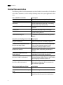
The following tables list the documentation associated with the current release. For details on
each of these documents, as well as for help obtaining them, refer to your application’s release
notes.
User and Reference Guides
Description
User’s Guide
Detailed instructions on using the software.
What’s New
A complete list of the new features for this release.
Online Help
All of the information in the User’s Guide along
with powerful search functionality
Hot Keys Reference Guide
A complete list of hot keys for commonly used
functions
Hot Keys Card
A list of the most frequently used hot keys
Release Notes
A complete list of documentation and information
on late-breaking features
Fixed and Known Bug List
A complete list of fixed and known bugs for this
release
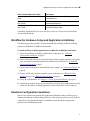
Installation and Configuration Guides Description
Hardware Setup Guide
(for your workstation)
Information on how to set up your workstation’s
video I/O components and other peripherals
Installation and Configuration Guide
(for your operating system)
Information on how to install and configure the
Linux® or IRIX® operating system on your
workstation should you require to do so
Stone and Wire Filesystem and Networking Procedures for configuring your Autodesk Stone®
filesystem, Wire® networking, and Wiretap™
Guide (for this release)
services.
2
Stone Direct Configuration Guide
(for this release)
Detailed connectivity diagrams and configuration
procedures for your Stone storage arrays
Software Installation Guide
(for Linux® or IRIX® workstations)
Information about installing and licensing your
Autodesk Editing or Effects software and installing
and configuring Autodesk Cleaner® XL
Configuration File Reference Guide
(for Linux or IRIX workstations)
Information on how to modify the initialization
and project configuration files associated with
your Autodesk application
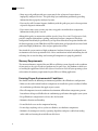
Other Product Reference Guides
Description
Autodesk Cleaner XL User's Guide
Information on how to use Cleaner XL.
Autodesk Cleaner XL Troubleshooting
Guide
Troubleshooting information for Cleaner XL.
Using QuickTime with Linux Workstations
Information on how to use Cleaner XL to convert
QuickTime® files for use on Linux workstations
Workflow for Hardware Setup and Application Installation ❚❘❘
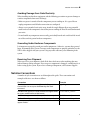
Other Product Reference Guides
Description
Autodesk Burn Installation and User’s
Guide
Information on how to install, set up, and use
Autodesk Burn™
Autodesk Backburner Installation and
User’s Guide
Information on how to install, set up, and use
Autodesk Backburner™
Autodesk Wiretap Web Installation and
User’s Guide
Information on how to install, set up, and use
Autodesk Wiretap™ Web
Consult the Autodesk Web site at www.autodesk.com/discreet-documentation for the latest
version of all documents.
Workflow for Hardware Setup and Application Installation
The following procedure provides the general workflow for installing an Effects or Editing
product on an IBM 6221 or IBM 6224 workstation.
To install an Effects or Editing application on an IBM 6221 or IBM 6224 workstation:
1. Review the guidelines for working with hardware components. See “Hardware
Configuration Guidelines” on page 3.
2. Connect all peripherals (mouse, keyboard, Wacom® tablet, graphics monitor) to the proper
ports, and connect your workstation to the Autodesk® Wire network. See “Peripherals
Connection Diagrams” on page 7.
3. Connect your workstation to Autodesk Stone Direct storage. See “Connecting Storage” on
page 10.
4. Connect a VTR and a broadcast monitor to your workstation. See “IBM 6224 Video
Wiring” on page 17 or “IBM 6221 Video Wiring” on page 15.
5. Set up the audio hardware. See Chapter 4, “Setting Up Audio Hardware,” on page 27.
6. Perform the procedures in the Software Installation Guide for Linux workstations to install
and license your Effects or Editing application, and to install Cleaner XL (if required).
Hardware Configuration Guidelines
In most cases, hardware integration and application installation is done on delivery by an
authorized technician, and some of the procedures in this guide may not be necessary. Still, it is
a good idea to read through all chapters to familiarize yourself with the configuration
procedures for the following reasons:
3
1 Introduction
• Many suspected problems with your system may be due to loosened connections or
improperly configured devices. This guide helps you troubleshoot problems by providing
information about properly configured systems.
• If you need to call Customer Support, familiarity with this guide puts you in a better position
to provide diagnostic information.
• If you want to move your system at any time, or upgrade certain hardware components,
information in this guide is crucial.
Although this guide, in conjunction with the Autodesk Stone Direct 2007 Configuration Guide,
provides complete information regarding configuring hardware components, hardware
configuration should only be performed by an experienced hardware integrator familiar with
the Linux operating system, IBM APro and ZPro workstations, and peripherals associated with
professional high-performance video and post production of film.
Your Autodesk system consists of high-performance hardware that must be configured in an
environment suited to its operational needs. Other considerations include minimizing the risk
of damage due to static discharge and ensuring all components are properly grounded.
Memory Requirements
The amount of memory required for your Effects or Editing system depends on the resolution
of your projects, the type of work you perform and, in some cases, the platform on which you
are running the application. Refer to the Software Installation Guide for your operating system
to determine the memory requirements for your Effects or Editing application.
Ensuring Proper Environmental Conditions
You should consider the following environmental guidelines for all hardware configuration:
• Make sure the rack in which hardware components are installed is open or ventilated. Follow
the ventilation specifications that apply to your system.
• Place all components in an air-conditioned environment. All hardware components generate
heat and must be kept cool. Follow the air-conditioning specifications that apply to your system.
• Keep all hardware components in a clean, dust-free location.
• Minimize vibration and humidity.
• Do not block the vents on the component housing.
• Do not drape anything, such as a jacket or a blanket, over hardware components.
• Minimize electromagnetic noise by separating digital data and power cables from analog
audio cables and running them in different cable ducts.
4
Notation Conventions ❚❘❘
Avoiding Damage from Static Electricity
When installing any hardware equipment, take the following precautions to prevent damage to
sensitive components from static discharge:
• Make sure power is turned off on the component you are working on. It is a good idea to
unplug components until all other connections are configured.
• Always wear a grounded static wrist strap. Attach the strap’s alligator clip to any grounded
metal surface on the component’s chassis that you are working on. Place the wristband around
your wrist.
• Do not handle any components unnecessarily, particularly boards and cards that slide in and
out of slots on their parent hardware components.
Grounding Audio Hardware Components
It is important to properly ground your audio components. Otherwise, you may have ground
loops, or humming in the system. To ensure audio components are properly grounded, use the
XLR-3 cables shipped with your system. Using any other cables may cause humming in the
system.
Receiving Your Shipment
When you receive your shipment, check all the boxes for dents or other markings that may
indicate damage during transport. If you suspect a component is damaged, carefully inspect it
before setting up the system. If you receive a damaged component, call Customer Support.
Notation Conventions
A number of style conventions are used throughout this guide. These conventions and
examples of their use are shown as follows.
Convention
Example
Text that you enter in a command line or shell appears in
Courier bold. You must press the ENTER key after each
command.
rpm -qa
Variable names appear in Courier, enclosed in angle brackets. <variable_name>
No spaces are allowed in variable names.
Variables that appear enclosed in square brackets are optional. [<filename>]
Feedback from the command line or shell appears in Courier.
limit coredumpsize
Directory names, filenames, URLs, and command line utilities
appear in italics.
/usr/discreet
5
1 Introduction
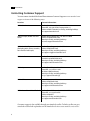
Contacting Customer Support
You can contact Autodesk Media and Entertainment Customer Support at www.autodesk.com/
support or in one of the following ways.
Location:
Contact Information:
Within the Americas:
Hotline (North America): 1-800-925-6442
Direct dial: 415-507-5256 (Country code = 1)
8 AM to 8 PM EST Monday to Friday, excluding holidays
[email protected]
Within Europe, Middle-East and
Africa:
Hotline (from London, UK): +44-207-851-8080
9 AM to 5:30 PM (local time)
Monday to Friday, excluding holidays
[email protected]
Within Asia Pacific:
(Excluding India, China, Australia,
New Zealand and Japan)
Hotline (from Singapore): +65-6555-0399
9 AM to 6 PM (local time)
Monday to Friday, excluding holidays
[email protected]
Within India:
Hotline (from Mumbai): +91-22-6695-2244
9:30 AM to 6:30 PM (local time)
Monday to Friday, excluding holidays
[email protected]
Within Japan:
Hotline (from Tokyo): 0120-107-290
Direct dial: +81-3-6221-1810
10 AM to 6 PM (local time)
Monday to Friday, excluding holidays
[email protected]
Within China:
Direct dial: +86-10-6505-6848
9 AM to 6 PM (local time)
Monday to Friday, excluding holidays
[email protected]
Within Australia and New Zealand: Hotline (from Melbourne): +1-300-36-8355
Direct dial: +61-3-9876-8355
8 AM to 6 PM AEST
Monday to Friday, excluding holidays
[email protected]
Customer support is also available through your Autodesk reseller. To find a reseller near you,
consult the reseller look-up database on the Autodesk web site at www.autodesk.com/resellers.
6
Connecting Peripherals
Summary
Peripherals Connection Diagrams . . . . . . . . . . . . . . . . . . . . . . . . . . . . . . . . . . . . . . . . . 7
Connecting the Keyboard and Mouse . . . . . . . . . . . . . . . . . . . . . . . . . . . . . . . . . . . . . . 9
Connecting the Tablet . . . . . . . . . . . . . . . . . . . . . . . . . . . . . . . . . . . . . . . . . . . . . . . . . . . . 10
Connecting to Gigabit Ethernet (GigE) Networks . . . . . . . . . . . . . . . . . . . . . . . . . . 10
Connecting Storage . . . . . . . . . . . . . . . . . . . . . . . . . . . . . . . . . . . . . . . . . . . . . . . . . . . . . . 10
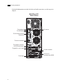
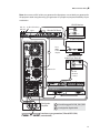
Peripherals Connection Diagrams
You must connect all hardware peripheral devices before you boot your workstation. The
following diagrams identify the ports to which the peripherals connect on IBM 6221 and IBM
6224 workstations.
In both diagrams, a 2-port QLA 2342 fibre channel adapter is shown. Your workstation may be
equipped with a 2-port QLA 2342 fibre channel adapter or a 4-port QLA 2344 fibre channel
adapter. See “Connecting Storage to the QLA Fibre Channel Adapter” on page 11.
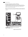
In the IBM APro diagram, a 2-port Gigabit Ethernet network card is shown.Your workstation
may be equipped with a 1-, 2-, or 4-port Gigabit Ethernet network card. See “Connecting to
Gigabit Ethernet (GigE) Networks” on page 10.
7
2 Connecting Peripherals
For detailed information associated with video and audio connections, see their respective
chapters.
IBM ZPro 6221
Workstation
To keyboard
To mouse
To USB tablet
To DVI-Ramp control
(Optional)
To house network
To graphics monitor
(use left connector)
To graphics sync input
To Wire network
To storage
8
To DVS I/O
breakout box (BOB)
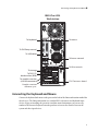
Connecting the Keyboard and Mouse ❚❘❘
IBM APro 6224
Workstation
To keyboard
To mouse
To DVI-Ramp control
To USB tablet
To house network
To Wire network
To storage
To DVS I/O
breakout box (BOB)
To graphics monitor
(use left connector)
DVS Centaurus board
Graphics monitor
reference sync
Connecting the Keyboard and Mouse
Connect the keyboard and mouse to the ports on the back of the Linux workstation marked for
these devices. The Linux workstation uses standard PS/2-style mouse and keyboard input
devices. If you are installing the system in a machine room environment, you can use any
number of PS/2 mouse/keyboard extender products to increase the distance between the
system and these input devices.
9
2 Connecting Peripherals
Connecting the Tablet
The Wacom® Intuos USB tablet is shipped with your system. Connect this tablet to the USB
extender and the Linux workstation before booting the workstation and before installing the
software. For connection information, refer to the appropriate diagram in “Peripherals
Connection Diagrams” on page 7.
All customization with respect to the tablet, including setting tablet margins, should be done in
the Preferences menu of your application. For help, see the description of Pointer preferences in
the user’s guide for your application.
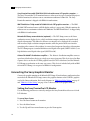
Connecting to Gigabit Ethernet (GigE) Networks
You must use the correct Gigabit Ethernet network card to connect your Linux workstation to
the Wire network. Otherwise, you may degrade the performance of your Wire network. For
information on how to configure the GigE adapter, refer to the Stone and Wire Filesystem and
Networking Guide. Consult the “Peripherals Connection Diagrams” on page 7 as a reference for
network interface card (NIC) locations.
Do the following to maximize Wire network performance in your facility:
• Connect ports from the add-on network card to the switch used for your Wire network.
• Connect the house network to the on-board network port shown in “Peripherals Connection
Diagrams” on page 7. Do not use any of the ports on the add-on network card for your house
network. If the house network is not connected to the on-board network port, consult your
system administrator for help reconfiguring it.
• Use high-quality Category 6 (Cat 6) network cables when connecting the Linux workstation
to your Wire network switch.
Connecting Storage
You can connect your Linux workstation to two types of storage:
• One or more Stone Direct disk arrays that provide storage to individual workstations. Refer to
the Stone Direct 2007 Configuration Guide for information on connecting disk arrays to your
workstation.
• A Stone Shared storage area network (SAN) that provides shared storage for multiple
workstations. Refer to the Autodesk Stone Shared Installation and Configuration Guide for
information on connecting your workstation to a SAN. This storage option is not available for
the 6221 platform.
10
Connecting Storage ❚❘❘
!
WARNING: Consult the Autodesk Web site at www.autodesk.com/discreet-documentation for the
latest version of these guides.The 64-bit Linux operating system has a file system limit of 4
terabytes for SD and 8 terabytes for HD. The 32-bit Linux operating system has a file system limit
of 4 terabytes for either SD or HD. When configuring your storage, ensure each partition does not
exceed this limit, and that inodes are correctly configured. Refer to the Stone and Wire Filesystem
and Networking Guide.
Connecting Storage to the QLA Fibre Channel Adapter
If your system is configured with the QLA 2342 fibre channel adapter, connect the storage to
ports 1 and 2. Archiving devices are not supported with the QLA 2342 fibre channel adapter.
If your system is configured with the QLA 2344 fibre channel adapter, connect the storage to
ports 2 and 3 (the two innermost ports). Connect archiving devices or Stone Shared to ports 1
and 4 (the two outermost ports).
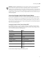
Setting the QLogic QLA Fibre-Channel Adapter BIOS
Use the following settings to correctly configure the QLogic™ QLA Fibre-Channel Adapter
HBA and Advanced Adapter. Either a QLA 2342 or QLA 2344 Fibre-Channel Adapter can be
used. Set the HBA settings to the following values.
HBA Settings
Value
Host Adapter BIOS
Disabled
Frame Size
2048
Loop Reset Delay
5
Adapter Hard Loop ID
Disabled
Hard Loop ID
No Effect
Spinup Delay
Disabled
Connection Options
2 for Direct Connect
Fibre Channel Tape Support
Disabled
Data Rate
1- for all ports of the QLA 2342
Adapter
Data Rate
1- for ports 2 & 3 of the QLA 2344
Adapter
Data Rate
2- for ports 1 & 4 of the QLA 2344
Adapter
Set the Advanced Adapter Settings to the following values.
11
2 Connecting Peripherals
Hardware RAID Configuration
If you are using IR-series hardware RAID disk arrays, you must configure the Discreet® Storage
Manager (DSM) on the Linux workstation. For instructions, refer to the “Installing the DSM on
Linux” section of the Discreet Storage Manager Release Notes, 2nd edition. Consult the storage
area of the Autodesk Web site at www.autodesk.com/discreet-documentation for the latest
version of this guide.
If you are using XR-series hardware RAID disk arrays, it is not necessary to install the Autodesk
Stone Storage Manager on the Linux workstation.
12
Setting Up Video Hardware
Summary
Video Hardware Components . . . . . . . . . . . . . . . . . . . . . . . . . . . . . . . . . . . . . . . . . . . .
Connecting the Sony Graphics Monitor . . . . . . . . . . . . . . . . . . . . . . . . . . . . . . . . . . .
IBM 6221 Video Wiring . . . . . . . . . . . . . . . . . . . . . . . . . . . . . . . . . . . . . . . . . . . . . . . . . . .
IBM 6224 Video Wiring . . . . . . . . . . . . . . . . . . . . . . . . . . . . . . . . . . . . . . . . . . . . . . . . . . .
Setting Up VTR Emulation (Smoke Only) . . . . . . . . . . . . . . . . . . . . . . . . . . . . . . . . . .
13
14
15
17
21
Video Hardware Components
You use the video hardware components described in this section to create video I/O and
graphics-to-video paths. Video I/O enables the input and output of video using a VTR or live
feed. The DVS video board is the hardware component used for the video I/O path, audio, and
VTR control. Graphics-to-video enables output from the graphics display to be converted to a
video signal for display on a broadcast monitor. You create a graphics-to-video path to preview
clips as they appear when broadcast. The NVIDIA graphics board and optional DVI-Ramp are
the hardware components used for this path.
The only video hardware you must provide are a sync generator, a VTR, and an SD or HD SDI
broadcast monitor. The following components are included in your hardware shipment.
DVS Centaurus board and Breakout Box II DVS or SDStation board and SDStation Pro
breakout box — The DVS Breakout Box II connects to the Centaurus board on an IBM 6224
workstation and handles NTSC, PAL, and HD resolutions at a depth of 8 bits. The DVS
SDStationPro breakout box connects to the SDStationBoard on an IBM® 6221 workstation and
handles NTSC and PAL resolutions at a depth of 8 bits.
NVIDIA NV35 Quadro FX 3000G graphics board — The NVIDIA Quadro® FX 3000G is
the graphics board used on both IBM 6221 and 6224 workstations. The frame lock and genlock
features of this board allow video output from the NVIDIA Quadro FX 3000G board to be
synchronized with external devices.
13
3 Setting Up Video Hardware
Sony PremierPro model SDM-P234/B 23-inch widescreen LCD graphics monitor —
The Sony™ PremierPro™ LCD monitor features a widescreen 16:9 aspect ratio for HD projects.
With this monitor, the software runs at a maximum resolution of 1920x1154. The Sony
PremierPro monitor is shipped with IBM 6224 workstations.
IBM ThinkVision C220p model 673560N 22-inch CRT graphics monitor — The IBM
673560N CRT monitor features a full flat display with a 4:3 aspect ratio. With this monitor, the
software runs at a maximum resolution of 1280x1024. The IBM ThinkVision™ is shipped only
with IBM 6221 workstations.
Miranda DVI-Ramp external device (optional) — The DVI-Ramp connects the Linux
workstation to two display devices: a high-resolution computer monitor and a professional
digital video monitor. This allows the software user interface to be displayed on a standard,
non-interlaced, high-resolution computer monitor, while the portion of the user interface
containing video content (video window) is extracted and output on a broadcast video monitor.
The DVI-Ramp outputs a standard definition serial digital video signal (SMPTE-259M-C) or a
high definition serial digital video signal (SMPTE-292M).
Altinex DA1804NT distribution amplifier — The Altinex® distribution amplifier connects
up to four video hardware devices to a single sync source/generator. This device is used to allow
separate devices such as the NVIDIA graphics board, the DVS video board, and the Miranda
DVI-Ramp to synchronize to the same sync source. This device is included only with an IBM
6224 with DVI-Ramp; it is not part of an IBM 6221 configuration.
Connecting the Sony Graphics Monitor
Connect the graphics monitor to the Miranda DVI-Ramp. If your hardware configuration does
not include the Miranda DVI-Ramp, connect the graphics monitor to the NVIDIA® graphics
card of the Linux workstation. Refer to the diagrams in “IBM 6224 Video Wiring” on page 17
and “IBM 6221 Video Wiring” on page 15 to see how to connect the graphics monitor.
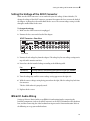
Setting the Sony PremierPro LCD Monitor
Use the following procedures to correctly configure the Sony PremierPro widescreen 23-inch
LCD Monitor.
To set up Zoom Factor:
1. Press the Power button on the monitor.
2. Press the Menu button.
3. Use the Up and Down arrow buttons to go to the Zoom option.
14
IBM 6221 Video Wiring ❚❘❘
4. Select REAL.
5. Press OK.
6. Press Menu.
To set the Auto Adjust Factor:
1. Press the Power button on the monitor.
2. Press the Menu button.
3. Use the Up and Down arrow buttons to go to Screen A.
4. Press OK.
5. Select Auto.
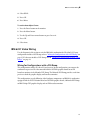
IBM 6221 Video Wiring
Use the diagrams in this section to wire the IBM 6221 workstation for SD video I/O. If your
configuration includes a DVI-Ramp, refer to “Wiring for Configurations with a DVI-Ramp” on
page 15. If it does not include a DVI-Ramp, refer to “Wiring for Configurations without a DVIRamp)” on page 16.
Wiring for Configurations with a DVI-Ramp
This configuration enables SD video I/O and preview. In this configuration, you connect the
workstation to preview SD video material from the NVIDIA graphics board on an SDI
broadcast monitor via the Miranda DVI-Ramp. The Miranda DVI-Ramp provides a real-time
preview to both the graphics display and broadcast monitor.
This configuration uses the following video hardware components: an IBM 6221 workstation
equipped with the DVS SDStation board and NVIDIA graphics board, a Miranda DVI-Ramp,
an IBM C220p CRT graphics display, and an SDI broadcast monitor.
15
3 Setting Up Video Hardware
Generic SD VTR
Video Player/Recorder
(not included)
IN
O U T
1 SDI IN
2 SDI OUT
3 CVBS OUT
4 REF IN
5
DIGITAL VIDEO
REMOTE RS-422
SYNC
ANALOG VIDEO
OUT
IN
VIDEO (REF)
OUT
LTC
GPI
IN
DIGITAL AUDIO IN
OUT
CH 1/2
CH 3/4
CVBS
5 Use cable tagged
AUDIO (WOLK)
DL.CAB_SML_REM
DIGITAL AUDIO OUT
CH 1/2
CH 3/4
CH 5/6
CH 7/8
ANALOG AUDIO OUT
DVS BOB (Front)
DVS BOB (Back)
Linux Workstation
IN
1
SDI Monitor
2
Graphics Monitor
3
4
DVI to
RGB HV
68 pin VHD connector
Miranda
DVI
Ramp
SD Ref DVI 1
S y nG
c en
I
0
NTSC/PAL Sync
(not provided)
S y nG
c en
BNC to
VGA
connector
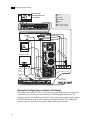
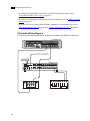
Wiring for Configurations without a DVI-Ramp)
This configuration enables SD video I/O and preview. In this configuration, you connect the
workstation to preview SD video material from the NVIDIA graphics board on an SDI
broadcast monitor. The NVIDIA board sends the video signal to the graphics display and the
DVS SDStation board sends the video signal to the broadcast monitor. This configuration
results in a preview lag between the graphics display and broadcast monitor.
16
IBM 6224 Video Wiring ❚❘❘
This configuration uses the following video hardware components: an IBM 6221 workstation
equipped with the DVS SDStation board and NVIDIA graphics board, an IBM C220p CRT
graphics display, and an SDI broadcast monitor.
Generic SD VTR
Video Player/Recorder
SDI Monitor
RGB Monitor (Optional)
IN
IN
IN
IN
S y nG
c en
O U T
S y nG
c en
NTSC/PAL Sync Generator
(not included)
IN
NTSC/PAL Sync
Remote In
5
DIGITAL VIDEO
SYNC
ANALOG VIDEO
OUT
IN
REMOTE RS-422
VIDEO (REF)
OUT
LTC
GPI
IN
DIGITAL AUDIO IN
OUT
CH 1/2
CH 3/4
CVBS
AUDIO (WOLK)
DIGITAL AUDIO OUT
CH 1/2
CH 3/4
CH 5/6
CH 7/8
ANALOG AUDIO OUT
5 Use cable tagged
DL.CAB_SML_REM
DVS BOB (Front)
DVS BOB (Back)
Linux Workstation
1 REF IN
Set
Terminal
Switch
To Off
2 CVBS OUT
3 SDI OUT
4 SDI IN
1
2
Graphics Monitor
DVI to
RGB HV
3
4
5 BNC cables
BNC to VGA
connector
68 pin VHD connector
IBM 6224 Video Wiring
Use the diagrams in this section to wire the IBM 6224 workstation for video I/O. If your
configuration includes a DVI-Ramp, refer to “Wiring for Configurations with a DVI-Ramp” on
17
3 Setting Up Video Hardware
page 18. If it does not include a DVI-Ramp, refer to “Wiring for Configurations without a DVIRamp” on page 20.
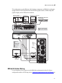
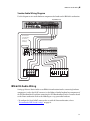
Wiring for Configurations with a DVI-Ramp
This configuration enables SD or HD I/O and preview. In this configuration, you connect the
workstation to preview SD or HD video material from the NVIDIA graphics board on a
broadcast monitor via the Miranda DVI-Ramp. The Miranda DVI-Ramp provides a real-time
preview to both the graphics display and broadcast monitor.
This configuration uses the following video hardware components: an IBM 6224 workstation
equipped with the DVS Centaurus board and NVIDIA graphics board, a Miranda DVI-Ramp,
a Sony PremierPro 23-inch LCD graphics display, an HD/SDI broadcast monitor, and an
Altinex distribution amplifier.
Note the following about this wiring diagram:
• The sync source is connected to the Altinex distribution amplifier. The sync source should
never be connected directly to the Linux workstation.
• The VTR is connected to the SDI In A and SDI Out A ports on the Linux workstation. The SDI
In B and SDI Out B ports are not used for VTR capture or playback.
• VTR control is provided through the RS-422 B port on the main DVS Breakout Box II. The
RS-422 A port on the breakout box is not used.
18
IBM 6224 Video Wiring ❚❘❘
NOTE: Do not use an NTSC or PAL sync generator for HD projects; use a tri-level sync generator for
HD projects instead. Using the wrong sync generator for a project may impact the stability of your
workstation.
HD/SDI Monitor
HD SD 75 Ohm Terminator
Ref Ref
DVI 1
RS232 Miranda DVI Ramp
S D I IN
I
0
H D S D I IN
Graphics Monitor
IBM APro 6224 Workstation
Use a
5BNC
to VGA
adapter
1
VGA
VGA
DVI
Generic HD/SD VTR
Video Player/Recorder
IN
O U T
Serial 1
RS-422
Machine
Control
2
1
IN
OUT
1/2
3/4
5/6
7/8
1/2
3/4
5/6
7/8
RS.422A
AUDIO
WClk
CVBS
GPI
RS.422B
LTC
IN
DIGITAL AUDIO
OUT
DVS BOB (Front)
DVS BOB (Back)
SYSTEM
Distribution
Amplifier
AES/EBU AUDIO
AES/EBU AUDIO
1 Use cable tagged DL.CAB_SML_REM
S y nG
c en
S y nG
c en
2 Use digital-to-digital cable
from house sync generation (Trilevel/NTSC/PAL)
(not included)
19
3 Setting Up Video Hardware
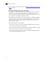
Wiring for Configurations without a DVI-Ramp
This configuration enables SD or HD I/O on a VTR. It uses the following video hardware
components: an IBM 6224 workstation equipped with the DVS Centaurus board and NVIDIA
graphics board, a Sony PremierPro 23-inch LCD graphics display, an HD/SDI broadcast
monitor, and the Altinex distribution amplifier.
NOTE: Do not use an NTSC or PAL sync generator for HD projects; use a tri-level sync generator for
HD projects instead. Using the wrong sync generator for a project may impact the stability of your
workstation.
Graphics Monitor
IBM APro 6224 Workstation
Use a
5BNC
to VGA
adapter
VGA
VGA
DVI
Generic HD/SD VTR
Video Player/Recorder
IN
O U T
RS-422
Machine
Control
1
IN
OUT
1/2
3/4
5/6
7/8
1/2
3/4
5/6
7/8
RS.422A
AUDIO
WClk
CVBS
GPI
RS.422B
LTC
IN
DIGITAL AUDIO
OUT
DVS BOB (Front)
DVS BOB (Back)
S y nG
c en
S y nG
c en
SYSTEM
AES/EBU AUDIO
AES/EBU AUDIO
from house sync generation (Trilevel/NTSC/PAL)
(not included)
1 Use cable tagged DL.CAB_SML_REM
20
Setting Up VTR Emulation (Smoke Only) ❚❘❘
Setting Up VTR Emulation (Smoke Only)
You can configure Autodesk Smoke® to emulate a VTR for both input and output in real time.
You control the emulator from the application or device that sees Smoke as a VTR.
The following procedure describes how to configure the hardware for VTR emulation. Consult
the “VTR Emulation” chapter in the Autodesk Smoke 2007 User’s Guide for more information on
VTR emulation.
NOTE: VTR emulation is not supported on the IBM 6221 platform.
To configure hardware for VTR emulation:
1. Connect the video I/O cables between the devices involved in the VTR emulation process
(out-to-in/in-to-out). Make sure the connections support the video standard you want to
work with.
If you intend to use the emulator as a Player, it is recommended that you connect one black
or colour bar SDI signal to the input of the system serving as the VTR emulator. This ensures
the Player is stable and correctly sync’ed.
NOTE: VTR emulation requires a Smoke workstation with a video board. The Video keyword for
the corresponding device must be uncommented in the software initialisation configuration
file. For an explanation of this keyword, refer to the Configuration File Reference Guide for your
operating system.
2. Connect the audio I/O cables between the devices involved in the VTR emulation process
(out-to-in/in-to-out).
If you intend to use the emulator as a Player, it is recommended that you connect an external
AES signal such as a tone to the input of the system serving as the VTR emulator. This
ensures the Player is stable and correctly sync’ed.
3. Connect an RS-422 control cable to the serial ports between the devices in the VTR
emulation process. Make sure the serial ports correspond to those defined by the Emulator
keywords in the software initialisation configuration file, inti.cfg. For an explanation of this
keyword, refer to the Configuration File Reference Guide for your operating system.
NOTE: The RS-422 cables for VTR emulation require custom pinouts. See “VTR Emulation RS-422
Control Cables” on page 21.
4. Make sure the appropriate video and audio sync setup is in place.
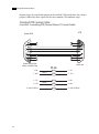
VTR Emulation RS-422 Control Cables
Custom cables are required to control the VTR emulator. The pinouts required by the cable
depend on the workstation and device involved in the VTR emulation process. The following
21
3 Setting Up Video Hardware
diagrams depict the control cable pinouts for the standard VTR control cables (for reference
purposes) followed by those required for the most common VTR emulation setups.
Standard VTR Control Cable:
Linux/AJA Controlling VTR (Normal Video I/O Control Cable)
VTR
Linux/AJA
1
6
2
7
3
8
4
9
5
1
6
2
7
3
8
4
9
5
OEM-2K: MALE DB9
OEM-LH: FEMALE DB9
MALE DB9
2 - RX 7 - RX +
3 - TX 8 - TX+
4 - GND (SHIELD)
22
WHT
2 - TX -
BLK
7 - TX +
RED
3 - RX -
BLK
8 - RX+
GND
4 - GND (SHIELD)
PAIR 1
PAIR 2
Setting Up VTR Emulation (Smoke Only) ❚❘❘
VTR-Emulation Control Cable:
Linux/AJA Master Controlling Linux/AJA Emulator
Linux/AJA Master
Linux/AJA Emulator
1
6
2
7
3
8
4
9
5
1
6
2
7
3
8
4
9
5
OEM-2K: MALE DB9
OEM-LH: FEMALE DB9
OEM-2K: MALE DB9
OEM-LH: FEMALE DB9
2 - RX 7 - RX +
8 - TX 3 - TX+
4 - GND (SHIELD)
WHT
8 - TX -
BLK
3 - TX +
RED
2 - RX -
BLK
7 - RX+
GND
4 - GND (SHIELD)
PAIR 1
PAIR 2
23
3 Setting Up Video Hardware
VTR-Emulation Control Cable:
SGI Master Controlling Linux/AJA Enulator
Linux/AJA Master Controlling SGI Emulator
SGI
(Master or Emulator)
Linux / AJA
(Master or Emulator)
1
6
2
7
3
8
4
9
5
1
6
2
7
3
8
4
9
5
OEM-2K: MALE DB9
OEM-LH: FEMALE DB9
FEMALE DB9
3 - TX 4 - TX +
2 - RX 6 - RX+
5 - GND (SHIELD)
24
WHT
2 - RX -
BLK
7 - RX +
RED
8 - TX -
BLK
3 - TX +
GND
1 - GND (SHIELD)
PAIR 1
PAIR 2
Setting Up VTR Emulation (Smoke Only) ❚❘❘
VTR-Emulation Control Cable:
3rd-Party Device Master Controlling Linux/AJA Emulator
3rd-Party Device Master
Linux/AJA Emulator
1
6
2
7
3
8
4
9
5
1
6
2
7
3
8
4
9
5
OEM-2K: MALE DB9
OEM-LH: FEMALE DB9
MALE DB9
2 - RX 7 - RX +
8 - TX 3 - TX+
4 - GND (SHIELD)
WHT
8 - TX -
BLK
3 - TX +
RED
2 - RX -
BLK
7 - RX+
GND
4 - GND (SHIELD)
PAIR 1
PAIR2
25
3 Setting Up Video Hardware
26
Setting Up Audio Hardware
Summary
About Discreet Native Audio . . . . . . . . . . . . . . . . . . . . . . . . . . . . . . . . . . . . . . . . . . . . . .
Understanding Remote vs Local Control of the Converter . . . . . . . . . . . . . . . . . .
Audio Hardware Components . . . . . . . . . . . . . . . . . . . . . . . . . . . . . . . . . . . . . . . . . . . .
Setting the Voltage of the ADAT Converter . . . . . . . . . . . . . . . . . . . . . . . . . . . . . . . .
IBM 6221 Audio Wiring . . . . . . . . . . . . . . . . . . . . . . . . . . . . . . . . . . . . . . . . . . . . . . . . . . .
IBM 6224 Audio Wiring . . . . . . . . . . . . . . . . . . . . . . . . . . . . . . . . . . . . . . . . . . . . . . . . . . .
Recommended DIP Switch Settings . . . . . . . . . . . . . . . . . . . . . . . . . . . . . . . . . . . . . . .
Updating the Software Initialisation Configuration File . . . . . . . . . . . . . . . . . . . .
27
28
28
29
29
31
33
34
About Discreet Native Audio
Discreet Native Audio is an audio subsystem integrated with the application. On Linux
platforms, Discreet Native Audio is based on the following configurations.
Workstation
Configuration
IBM 6221
DVS SDStationPro breakout box and the DVS SDStation board
IBM 6224
Balanced Audio breakout box component of the DVS Breakout Box II
and the DVS Centaurus board.
Through the external Lucid ADAT converter (ADA 8824) that shipped with your system,
Discreet Native Audio offers the following features. All channels use 24-bit audio resolution.
Application
Features
Flint
2 audio tracks in playback
2 audio input channels
2 audio output channels
Smoke
32 audio tracks maximum
4 audio input channels (DVS SDStation board)
8 audio input channels (DVS Centaurus board)
8 audio output channels
27
4 Setting Up Audio Hardware
Additionally, you can store the audio captured from a VTR or from an imported file at 32 bits
on the framestore. Discreet Native Audio also supports 32-bit audio playback.
Configure audio hardware only after having configured all Linux workstations and video
hardware components.
Understanding Remote vs Local Control of the Converter
You can control the converter either remotely or locally. Remote control of the converter means
that you physically connect the workstation directly to the converter and adjust converter
settings through the audio preferences of the application. Local control means you adjust
converter settings manually, using the DIP switches on the back of the converter.
All diagrams in this chapter indicate the connection you must cable to enable remote control of
the converter.
Audio Hardware Components
The Discreet Native Audio hardware components are described as follows.
Lucid 8824 ADAT converter — Converts signals between the Linux workstation and all
digital or analog audio I/O devices.
DVS SDStationPro breakout box and SDStationBoard — The DVS SDStationPro
breakout box connects to the SDStation board on an IBM 6221 workstation. The SDStation
board is a half-length PCI-bus single board that provides real-time input and output of
uncompressed SD video signals as well as audio data at 24-bit resolution.
The SDStation board handles balanced AES/EBU audio signals from the SDStationPro
breakout box. For Autodesk Flint®, it handles two input and two output audio channels. For
Smoke, it handles four input and eight output audio channels.
DVS Balanced Audio breakout box and Centaurus board — The Balanced Audio
breakout box is the audio component of the DVS Breakout Box II. It provides connections for
audio I/O. This breakout box connects to the DVS Centaurus board on an IBM 6224
workstation. The Centaurus board provides real-time input and output of uncompressed SD
and HD video signals as well as audio data at 24-bit resolution.
The Centaurus board handles balanced AES/EBU audio signals from the Balanced Audio
breakout box. For Flint, it handles two input and two output audio channels. For Smoke, it
handles eight input and eight output audio channels.
28
Setting the Voltage of the ADAT Converter ❚❘❘
Setting the Voltage of the ADAT Converter
Make sure the ADAT converter is set to work with your site’s voltage (110 or 220 volts). To
change the voltage of the ADAT converter, you must first remove the fuse cover on the back of
the adapter. A voltage key is located behind the fuse cover. The current voltage setting is visible
through a small window in the cover.
To change the voltage:
1. Make sure the ADAT converter is unplugged.
2. Remove the fuse cover on the back of the adapter.
ADAT Converter—Rear View
AES/EBU
ADAT Optical
In
Out
Word ClockS/P DIF
Analog Inputs
In
7-8
5-6
3-4
AES/EBU
Out
1-2
8
7
6
7-8
5-6
1-2
8
7
6
5
4
Analog Outputs
3
2
1
3
2
1
In
110
Out
3-4
5
4
Fuse cover
3. Remove the red voltage key from the adapter. The voltage key has two voltage settings on its
top side and it contains two fuses.
4. Insert fuses for the intended voltage according to the following table.
For:
Insert:
110 volts AC
1/2 Amp, 250 VAC slow blowing fuses (Bussman type GDC-500 MA)
220 volts AC
1/4 Amp, 250 VAC slow blowing fuses (Bussman type GDC-250 MA)
5. Turn the voltage key until the correct voltage setting appears on the right side.
6. With the correct voltage setting facing you and on the right, slide the voltage key back into
the converter.
The fuse clicks when it is properly seated.
7. Replace the fuse cover.
IBM 6221 Audio Wiring
Setting up Discreet Native Audio on an IBM 6221 workstation involves connecting the
hardware components (such as the ADAT converter) to the DVS SDStationPro video breakout
box, and then connecting the video breakout box to ports on the Linux workstation. Refer to
the following to set up your audio hardware:
29
4 Setting Up Audio Hardware
• To configure the Lucid ADAT converter for use with the Linux workstation, refer to
“Recommended DIP Switch Settings” on page 33.
• To connect the SDStationPro breakout box to the 6221 workstation, refer to “IBM 6221 Video
Wiring” on page 15.
• To connect the Discreet Native Audio hardware components to the breakout box, refer to
“Flint Audio Wiring Diagram” on page 30 or “Smoke Audio Wiring Diagram” on page 31.
Flint Audio Wiring Diagram
Use this diagram to wire audio hardware components for Flint on the IBM 6221 workstation.
DVS BOB (Front)
DIGITAL VIDEO
VIDEO (REF)
OUT
LTC
GPI
REMOTE RS-422
SYNC
ANALOG VIDEO
OUT
IN
IN
DIGITAL AUDIO IN
OUT
CH 1/2
CVBS
AUDIO (WOLK)
DIGITAL AUDIO OUT
CH 3/4
CH 1/2
CH 3/4
CH 5/6
CH 7/8
ANALOG AUDIO OUT
To serial port 1 on workstation
(for remote control of converter)
Optical Cable
ADAT Converter
Analog Inputs
AES/EBU In
ADAT Optical
In
Out
Word Clock
S/P DIF
7-8
5-6
AES/EBU
3-4
Out
1-2
8
7
6
7-8
5-6
3-4
1-2
8
7
6
5
4
Analog Outputs
3
2
1
3
2
1
IN
IN
In
110
Out
IN
IN
IN
IN
5
4
IN
OUT OUT OUT OUT
VTR
30
Audio mixer
IN
IN
IN
IN
IN
IBM 6224 Audio Wiring ❚❘❘
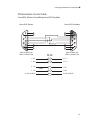
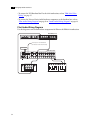
Smoke Audio Wiring Diagram
Use this diagram to wire audio hardware components for Smoke on the IBM 6221 workstation.
DVS BOB (Front)
DIGITAL VIDEO
VIDEO (REF)
OUT
LTC
GPI
REMOTE RS-422
SYNC
ANALOG VIDEO
OUT
IN
IN
DIGITAL AUDIO IN
OUT
CH 1/2
CVBS
AUDIO (WOLK)
DIGITAL AUDIO OUT
CH 3/4
CH 1/2
CH 3/4
CH 5/6
CH 7/8
ANALOG AUDIO OUT
To serial port 1
on workstation
(for remote
control of
converter)
Optical Cable
ADAT Converter
In
ADAT Optical
In
Out
ADAT
SYNC
Analog Inputs
AES/EBU In
Out
MIDI
In
Out/Thru
Word Clock
S/P DIF
7-8
5-6
AES/EBU
3-4
Out
1-2
8
7
6
7-8
5-6
3-4
1-2
8
7
6
5
4
Analog Outputs
3
2
1
3
2
1
IN
IN
In
110
Out
IN
IN
IN
IN
5
4
IN
IN
IN
IN
IN
IN
OUT OUT OUT OUT
VTR
Audio mixer
IBM 6224 Audio Wiring
Setting up Discreet Native Audio on an IBM 6224 workstation involves connecting hardware
components (such as the ADAT converter) to the Balanced Audio breakout box component of
the DVS Breakout Box II, and then connecting the DVS Breakout Box II to the Centaurus board
on the Linux workstation. Refer to the following to set up your audio hardware:
• To configure the Lucid ADAT converter for use with the Linux workstation, refer to
“Recommended DIP Switch Settings” on page 33.
31
4 Setting Up Audio Hardware
• To connect the DVS Breakout Box II to the 6224 workstation, refer to “IBM 6224 Video
Wiring” on page 17.
• To connect the Discreet Native Audio hardware components to the breakout box, refer to
“Flint Audio Wiring Diagram” on page 32 or “Smoke Audio Wiring Diagram” on page 33.
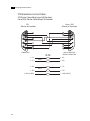
Flint Audio Wiring Diagram
Use this diagram to wire audio hardware components for Flint on the IBM 6224 workstation.
DVS BOB (Front)
IN
OUT
1/2
3/4
5/6
7/8
1/2
3/4
5/6
7/8
RS.422A
AUDIO
WClk
CVBS
RS.422B
GPI
LTC
DIGITAL AUDIO
IN
OUT
To serial port 1 on workstation
(for remote control of converter)
Optical Cable
ADAT Converter
Analog Inputs
AES/EBU In
ADAT Optical
In
Out
Word Clock
S/P DIF
7-8
5-6
AES/EBU
3-4
Out
1-2
8
7
6
7-8
5-6
3-4
1-2
8
7
6
5
4
Analog Outputs
3
2
1
3
2
1
IN
IN
In
110
Out
IN
IN
IN
IN
5
4
IN
OUT OUT OUT OUT
VTR
32
Audio mixer
IN
IN
IN
IN
IN
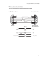
Recommended DIP Switch Settings ❚❘❘
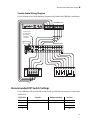
Smoke Audio Wiring Diagram
Use this diagram to wire audio hardware components for Smoke on the IBM 6221 workstation.
DVS BOB (Front)
IN
OUT
1/2
3/4
5/6
7/8
1/2
3/4
5/6
7/8
RS.422A
AUDIO
WClk
CVBS
RS.422B
GPI
LTC
DIGITAL AUDIO
IN
OUT
To serial port 1
on workstation
(for remote
control of
converter)
Optical Cable
ADAT Converter
In
ADAT Optical
In
Out
ADAT
SYNC
Analog Inputs
AES/EBU In
Out
MIDI
In
Out/Thru
Word Clock
S/P DIF
7-8
5-6
AES/EBU
3-4
Out
1-2
8
7
6
7-8
5-6
3-4
1-2
8
7
6
5
4
Analog Outputs
3
2
1
3
2
1
IN
IN
In
110
Out
IN
IN
IN
IN
5
4
IN
IN
IN
IN
IN
IN
OUT OUT OUT OUT
VTR
Audio mixer
Recommended DIP Switch Settings
Use the following table to set the DIP switches on the Lucid ADAT converter for use with a Linux
workstation.
DIP Switch
Controls
Required Setting
Position
1
Local/Remote
Local
Up
2
Input Sync Source
AES 1-2
Down
3
Down
4
Up
33
4 Setting Up Audio Hardware
DIP Switch
Controls
Required Setting
Position
5
Analog Output Source
ADAT
Down
6
AES/EBU Output Source
ADAT
Down
7
Optical Output Source
AES
Up
8
Meter Select
Output
Up
Input
Down
NOTE: Leave DIP switch 1 set to Local, regardless of whether you are controlling the converter
locally or remotely.
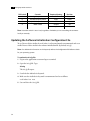
Updating the Software Initialisation Configuration File
To use Discreet Native Audio, the Audiodevice keyword must be uncommented and set to
enable Discreet Native Audio in the software initialisation file (by default, init.cfg).
NOTE: For additional information on this keyword, refer to the Configuration File Reference Guide
for your operating system.
To update the init.cfg file:
1. Log in to the application account and open a terminal.
2. Open the init.cfg file. Type:
dlcfg
The init.cfg file opens.
3. Search for the Audiodevice keyword.
4. Make sure the Audiodevice keyword is uncommented and set as follows:
Audiodevice DVS
5. Save and close the init.cfg file.
34
index
Index
A
ADAT converter, setting the voltage 29
audio hardware components 28
audio wiring
IBM 6221 29
IBM 6224 31
E
emulation, setting up VTR 21
H
hardware configuration guidelines 3
K
keyboard, setting up 9
M
monitor, connecting and setting up graphics 14
mouse, setting up 9
N
notation conventions 5
V
video hardware components 13
video wiring
IBM 6221 15
IBM 6224 16
voltage, setting for the ADAT converter 29
VTR emulation, setting up 21
35
Index
36