1
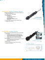
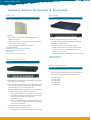
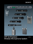
UHF Wireless Microphone Systems
Perfect
performance
(everytime)
this is not a rehearsal.
w w w.pro.sony-europe.com
Feel fre
to expres
you
UHF Wireless
Microphone Systems
Contents
Introduction
p.1
Handheld Transmitters
p.4
Belt pack transmitters
p.5
Stationery receivers
p.6 - p.7
Camera mount receivers
p.8
Powered A/V Mixer
p.9
The WL-800 Series has
Optional Accessories
p.10 - p.13
a rugged construction
Application Charts
p.14 - p.15
Sony offers two
alternative, compatible,
UHF wireless
microphone systems.
designed to withstand
the harsh environment
Specifications
p.16 - p.21
of location work and
the rigors of
day-to-day use in TV
studios and theatre
productions.
Sony is a Registered Trademark of Sony Corporation, Japan.
Reproduction in whole or in part without written permission of Sony Corporation is
prohibited. Design and specifications subject to change without notice.
Weights and dimensions shown are approximate.
1
e
ss
rself
Cost effective
The Pilot Tone; Auto Set-Up; Ceramic; Helical and SAW
filters; Isolator/Ring Modulator; direct 800MHz oscillation;
CPU and EE-PROM and the Sony unique frequency planning
all contribute to make a Sony wireless installation reliable
and cost efficient.
800MHz Band Operation
Sony UHF synthesized wireless microphone systems operate
between 774MHz and 862MHz (TV channels 59 to 69). This
extended frequency range provides the wide choice of
The Freedom Series
operating frequencies necessary for legal transmissions and
covers a limited
to avoid mutual interference.
number of cost
Advanced filtering
effective and lighter
models, making this
range more suitable
for interfacing with
The Sony wireless units all employ Helical, Ceramic and/or
SAW filters as appropriate. This offers stable reception and
thus good audio quality. It also ensures that a minimum of
the precious battery power available is used to supply many
power hungry LC type filters.
It also enables the unique miniaturization seen in most of the
Sony products.
audio installations in
seminar, conference
PLL Frequency Synthesis System
Phase Locked Loop (PLL) frequency synthesis systems and
and entertainment
applications.
direct 800 MHz oscillation are used both in transmitters and
receivers, assuring carrier stability and providing easy access
to multiple frequencies. These PLL controlled systems
enable up to 561, highly stable, operating frequencies to be
RF characteristics, audio
companding and Pilot Tone Squelch
generated within some of the models depending on local
regulations.
functions are the same for the two
systems to ensure their
compatibility.
UHF Wireless Microphone Systems
2
Space Diversity Reception System
Diversity Reception
A space diversity reception system provides unbroken
reception and increased service area by eliminating signal
dropout. Dual antenna inputs and reception circuitry
Ref
lec
ted
incorporated in the diversity receivers, receive signals over
two different transmission paths and select the stronger
Sig
nal
signal as the output. This switching operation is
Direct Signal
undetectable on the audio output of the receivers.
Wireless
Microphone
Pre-Programmed
Frequency Groups
Diversity Receiver
Phase differences between direct and
reflected signals causes cancellation
effects, giving changes in field intensity
Optimum combinations of calculated and practically tested
intermodulation-free frequencies are stored in the CPU of
each receiver to make it easy to chose the correct
frequencies for simultaneous multi-channel operation.
These frequencies are arranged in groups, with each group
pre-programmed to avoid interference when operating close
Field Intensity
to the frequencies of local TV transmitters.
Up to 10 intermodulation-free channels can be used
simultaneously within an 8MHz European TV channel. When
the group facility is selected on the receiver, the grouped
channels automatically step to their correct, intermodulationDistance
free frequencies and the transmitters are then set to
As the distance between the wireless
microphone and the receiver varies, the
signal picked up by the two individual
diversity antennas will also vary.
correspond with the channel information displayed on the
receiver LCD panel. The number of TV channels available
for use varies from area to area.
Sony has not only used ‘standard’ mathematical calculations
to find 3rd order intermodulation free channel plans. Sony
Antenna A
has also applied stringent practical tests. The result is that
FRONT END
IF
when using any of the Sony channel plans with 125kHz
DETECTOR
steps, no audible interference due to inter-transmitter
Selector
Output
intermodulation will occur. Consequently, all channels in a
multi-channel set-up should have the same audio quality.
COMPARATOR
When only applying pure mathematics without the practical
Antenna B
tests, there can in specific circumstances be minor
disturbances. This is a normal and non-manufacturer related
FRONT END
IF
DETECTOR
physical law. The special frequency plan calculated by Sony
The diversity receiver selects the
stronger of the two received signals as
its output.
is programmed into the receivers. By implementing this,
Sony offers the user unique and optimum freedom
from interference.
3
Remote Battery Alarm
on Receiver
Pilot Tone Squelch Circuitry for
Interference Free Reception
For added assurance of continued operation, you can now
The wireless microphone transmiters also transmitt a 32kHz tone signal along with
transmitters; the battery indicator on LCD starts flashing on
the program audio signal. In the receivers, a squelch circuit operates so that the
the handheld and body pack transmitter, both indicating
program signal is only output when the tone signal has been correctly received.
approx. one hour before the batteries go dead. On the
This squelch feature is designed to eliminate interference and noise because the
receiver, the battery indicator on the LCD and LED displays
receiver will only respond to transmissions carrying the tone signal.
also flash, helping to avoid the chance of battery failure at a
monitor the battery reserves of handheld*2 and body pack
critical moment.
Compander System for Wide
Dynamic Range and Low Noise
A linear 2:1 compander (compressor/expander) system is included for improved
audio dynamic range and low noise and interference. The time constants for attack
and release times are carefully chosen individually in the various transmitters to
match the application ensuring minimum signal to noise level while providing smooth
and superior audio quality.
RF Power
By using correct power for the application – both for ENG and stationary systems,
the battery consumption, low weight, small size and high security of interference in
multi channel systems that Sony offer are achievable in off the shelf solutions. This is
partly possible due to the use of filtering techniques such as helical and SAW filters
that draw a minimal amount of power from the incoming signal.
Channel Setting Memory
LCD for Operational Status Information
Transmitters and receivers have a memory back-up of
All receivers and transmitters feature a built-in, easy-to-read LCD panel which
operating frequency. When power is turned on, the previous
provides extensive status information. Most receivers*1 will display the diversity RF
channel setting is automatically recalled and displayed.
and AF signal strength, frequency and channel group chosen, and battery status of
the transmitter.
Most transmitters does in essence have the same information available in the display;
such as AF input level, and RF output, battery status, current channel number and
Note: The use of Sony wireless devices is regulated by the
group number, selected frequency, input attenuation setting, and accumulated
regulatory Authority of each country’s Government
operation time. The operation time is accumulated when unit is on, so if the time
Administration and authorised users are required to obtain
indication is reset to 0:00 at the time of battery replacement, it can display the total
an appropriate operating license.
running time of the battery.
*1 The WRT-820A/840A does not display the battery status
information transmitted.
*2 The WRT-867A does not transmit the battery status
information.
UHF Wireless Microphone Systems
Handheld transmitters
UHF Synthesised Wireless Handheld Microphones
WRT-807A
(Dynamic Capsule)
• High sound quality for vocals - powerful, crisp and clean sound as well as
presence in the low and mid frequency range
•• Choice of capsules
1) Dynamic hyper-cardioid microphone capsule which is employed in
the Sony F-780 professional vocal microphone
2) K-1335 narrow cardioid capsule
SUPPLIED ACCESSORIES
••• Lockable external on/off switch
Mic holder, PF 1/2-inch thread
•••• Easy-to-read LCD screen showing the selected channel, frequency, attenuator,
cumulative working time, AF level, RF level, & transmitter battery status
Stand adapters - PF 1/2-inch fi NS 5/8-inch
- PF 1/2-inch fi W 3/8-inch
••••• LCD for display of channels, attenuator and accumulated operating hours
OPTIONAL ACCESSORIES
•••••• One AA battery, operates continuously for 6 hours
K-1335 optional microphone capsule
••••••• 10 mW RF power output
•••••••• Battery alarm transmitted to compatible receivers
CHARACTERISTICS: SUPER-CARDIOID
••••••••• Newly-developed lockable power switch to prevent accidental operation
Frequency Response Characteristics
Directivity Characteristics
Response (dB)
4
Frequency (Hz)
WRT-810A
(Dynamic Capsule)
• Dynamic microphone with cardioid response
•• Ideal for ENG applications
••• LCD status indication
- RF carrier present
- Input signal above reference level
- TV channel selected
- Audio attenuator setting
- Wireless microphone channel selected
- Battery status
•••• Rugged housing for protection from rough handling
••••• Separate audio on-off and power on-off switches
•••••• Transmits battery status signal
SUPPLIED ACCESSORIES
Mic holder, PF 1/2-inch thread
Stand adapters - PF 1/2-inch fi NS 5/8-inch
- PF 1/2-inch fi W 3/8-inch
Handheld transmitters
5
WRT-830A
(Electret Condenser Capsule)
• Cardioid electret condenser microphone capsule with low handling noise,
ideal for vocal applications
•• Power output selectable to 10mW or 25mW
••• LCD status indication
- RF carrier present
- Input signal above reference level
- TV channel selected
- Audio attenuator setting
- Wireless microphone channel selected
- Battery status
SUPPLIED ACCESSORIES
Mic holder, PF 1/2-inch thread
Stand adapters - PF 1/2-inch fi NS 5/8-inch
- PF 1/2-inch fi W 3/8-inch
•••• Power on-off switch concealed to prevent accidental operation
••••• Transmits battery status signal
WRT-867A
(Dynamic Capsule)
• Hyper-Cardioid dynamic microphone capsule, also used in the acclaimed
F-780 microphone
- resilient body structure for extremely high quality sound
- high quality, edgewise-winding voice coil with lightweight
Copper Clad Aluminium Wire (CCAW) and an AINiCo magnet
- powerful, crisp and clear sound with middle and high
frequency range presence for critical vocal applications
•• Choice of capsules
1) Dynamic hyper-cardioid microphone capsule which is employed in
the Sony F-780 professional vocal microphone
2) K-1335 narrow cardioid capsule
SUPPLIED ACCESSORIES
Mic holder, PF 1/2-inch thread
Stand adapters - PF 1/2-inch fi NS 5/8-inch
••• 10mW power output
- PF 1/2-inch fi W 3/8-inch
Case
•••• Concealed LCD channel indication and operational controls
••••• LED battery status indication
CHARACTERISTICS: SUPER-CARDIOID
Directivity Characteristics
Response (dB)
Frequency Response Characteristics
Frequency (Hz)
UHF Wireless Microphone Systems
6
Belt pack transmitters
UHF Synthesised Body Pack Transmitters
WRT-805A
• Easy-to-read LCD screen showing the selected channel, frequency, attenuator,
cumulative working time, AF level, RF level, & transmitter battery status
•• Battery alarm transmitted for monitoring at compatible receivers
••• Compact, lightweight design with smoothly contoured body pack
•••• Continuous operation up to 6 hours with a single (LR6) AA-size
alkaline battery
••••• 10 mW RF power output
•••••• Newly developed 3.5 mm (5/32-inch) mini phone jack with stable lock
••••••• 1/4 wavelength whip antenna
•••••••• Switchable -40 dB/-60 dB input level and PHASE switches for guitar and
lavalier microphone
••••••••• Microphone options:
GC-0.7MP Guitar Cable, ECM-44BMP/ECM-77BMP/ECM-121BMP/
ECM-122BMP/ECM-166BMP Electret Condenser Microphone and
ECM-310BMP Electret Condenser Headset Microphone
WRT-822A
• Compact and lightweight magnesium alloy body
•• 10 mW RF power output
••• Easy-to-read LCD screen showing the selected channel, frequency, attenuator,
cumulative working time, AF level, RF level, & transmitter battery status
SUPPLIED ACCESSORIES
Soft case
•••• Accepts professional lavalier microphones fitted with SMC9-4P connector
••••• Continuous operation up to 8 hours with two (LR6) AA-size alkaline batteries
WRT-860A
• Ultra-compact design
•• 20mW power output for extended service area
••• Back-lit LCD status indication
- RF carrier present
- input signal above reference level
- TV channel selected / audio attenuator setting / accumulated
time-of-use
- wireless microphone channel selected and operating frequency in MHz
- cumulative battery operating time with manual reset
•••• Accepts professional lavalier microphones fitted with a
SMC9-4P connector
••••• Transmits a battery status signal
•••••• Continuous operation up to 6 hours with two (LR6) AA-size alkaline batteries
SUPPLIED ACCESSORIES
Soft case
Battery case
Mic cable EC-1.5CF
Carrying case
Stationery receivers
7
UHF Synthesized Diversity Tuner
WRR-802A
• UHF Synthesized Diversity Tuner
•• Single-channel Space Diversity Tuner, Half 19-inch rack width, 1U high
••• Same receiver module as the WRU-806A
Use of SAW filters for exceptional rejection of unwanted signals while
maintaining the best possible signal integrity of the wanted signal
•••• Output level control on front panel
••••• Front-mounted passive antennas (supplied)
•••••• MI industry standard fitting for rack mount adapters
••••••• AF, RF, and battery alarm indication by both LED and LCD to double
check operating condition
•••••••• Easy-to-read LCD display showing the selected channel and IM
free group, frequency, RF level, AF level and battery level status
••••••••• Two types of output connectors
- TRS Phone Balanced connector (6.3 mm dia.), LINE level; –20dBm
@ ref. deviation; headroom at +4dBm is 16dB
- XLR connector, MIC or LINE level. MIC level is –58dBm
@ref deviation
SUPPLIED ACCESSORIES
External 9V Power Adapter
Two passive 1/4 λ antennas
Receiver Base Unit
MB-806A
• Six channel operation in a 1U high, 19-inch rack unit
•• Expandable diversity receiver, accepting up to six WRU-806
(or WRU-801A) of any frequency supplied
••• RF input attenuation selector, 0dB/10dB
•••• Balanced output on XLR connectors, switchable MIC (–58dBm @ref
deviation)or LINE level. –20dBm @ ref. Deviation. With LINE level
selected, headroom at +4dBm is 16dB
••••• Front mounting of antennas possible with industry standard BNC/BNC
front adapter from many third party RF suppliers such as
Canford Audio
•••••• Space Diversity Reception for dependable RF reception
••••••• Auto channel assignment of additional receiver modules for instant
programming of interference-free multi-channel operation
•••••••• Supplied passive antennas for rear mounting
SUPPLIED ACCESSORIES
Two passive 1/4 λ antennas
(with provision for front mounting)
UHF Synthesized Receiver Unit
WRU-806A
• Dedicated plug-in diversity receiver module for MB-806A (or WRU-801A)
•• Auto channel assignment for extra receiver modules with self-detection and
skip of unusable channels
••• Pre-programmed groups stored in CPU for intermodulation free operation
of multi-channel systems
•••• AF, RF, and battery alarm indication by both LED and LCD to double
check operating condition
••••• Easy-to-read LCD display showing the selected channel and IM free
group, frequency, RF level, AF level and battery level status
•••••• Use of SAW filters for exceptional rejection of unwanted signals while
maintaining the best possible signal integrity of the wanted signal
••••••• Space Diversity Reception for dependable RF reception
UHF Wireless Microphone Systems
8
Stationery receivers
Two-Channel Diversity Receiver
WRR-840A
• Audio ouput level selectable to -20/-40/-60dBU @ref deviation
•• LCD status indication
- TV channel
- wireless microphone group and channel
••• LED indication of RF and audio signals present
•••• Provides power to two AN-820A antennas via coaxial cable
Single-Channel Diversity Receiver
WRR-820A
• WRR-820A identical to WRR-840A with the following exemptions:
•• Only one receiver channel
••• An additional RF diversity antenna through connector
Two-Channel Diversity Receiver
WRR-850A
• Outstanding RF performance and audio quality
•• Two diversity receivers for two-channel operation
••• RF mutting feature, selectable to operate to 15/25/35dBu
•••• Multi-function system information display includes
-
transmitter battery alarm (when receiving a WRT-860A)
antenna in use (A or B - diversity)
audio level
TV channel and operating frequency in MHz
wireless microphone group and channel number
muting level selected
output level selected
••••• Two-digit LED display of user-assigned identification number
•••••• Front panel headphone monitoring ouput with level control,
selectable to wither or both receivers
••••••• Provides power to two AN-820A antennas over coaxial cable
9
UHF Wireless Microphone Systems
10
Camera mount receivers
UHF Synthesized Portable Receivers
WRR-805A
• Compact, lightweight portable tuner for a wide variety of camcorders that
have a stereo mini jack
•• Easy-to-read LCD screen showing the selected channel, frequency,
attenuator, cumulative working time, AF level, RF level, &
transmitter battery status
••• Continuous operation up to 6 hours with a two AA-size (LR6)
alkaline batteries
•••• Newly developed 3.5 mm (5/32-inch) mini phone jack with stable
screw lock
••••• Ingenious camera mount; swivel, velcro, Betacam plate - single & dual
•••••• Flexible mounting position and direction for secure operation, for DV,
DVCAM, SX and DigiBeta
SUPPLIED ACCESSORIES
Attachment case with a belt clip
Operating instructions
Output cable
OPTIONAL ACCESSSORY
R805AttachmentS, for attachment
to other Sony cameras
R805AttachmentD, for attachment of two
WRR-805A's to other Sony cameras
••••••• Convenient headphone monitoring with volume control
•••••••• Comprehensive RF Squelch functions
WRR-810A
• Monitoring output
•• LED indication of received RF signal level
••• LCD status indication
- audio output
- TV channel selected
- frequency group selected
- wireless microphone channel selected
SUPPLIED ACCESSORIES
Betacam camcorder
mounting kit
1/4λ whip antenna
Output cable
- battery status
- mute function on/off
WRR-855A
(Diversity Receiver)
• Designed for use with Betacam camcorders, water resistant structure
•• LED indications of received RF signal level and audio output
••• LCD shows
- wireless microphone operating channel and group
SUPPLIED ACCESSORIES
1/4λ whip antenna
•••• Powered from camcorder
- direct interface for Sony Betacam SX camcorders
- via optional mounting adapter (BTA-801) with other Sony
camcorders
WRR-860A
(Diversity Receiver)
• Two way powering
- internal batteries
- 12V external DC supply
•• Monitoring output with level control
••• Back-lit LCD status indication
- four-level indication of received RF signal level for each antenna
- A or B antenna in use
- RF muting level selected
- audio output
- wireless microphone group and channel selected
- operating frequency in MHz
- cumulative battery operating time with manual reset
- external power connected
- muting level selected
SUPPLIED ACCESSORIES
Soft case, shoulder strap
Betacam camcorder mounting kit
1/4λ whip antenna x 2
Output cable
DC power cable
Spare battery case
Powered A/V Mixer With Freedom Receiver
SRP-X351P with WRU-806A
• 3U rackmounting
•• 4 balanced mircophone inputs (XLR)
••• signal/RF present LEDs on each channel, CLIP LEDs on outputs
•••• Accepts up to two WRU-806A Freedom Series receiver modules
Routed to Mic 1 & Mic 2 inputs
••••• +48V phantom power
•••••• front panel microphone input (1/4” jack) (MIC 4)
••••••• 3 stereo inputs
•••••••• 4 way A/V source selector (ST 3)
••••••••• 125W per channel (8Ω) Power Amplifier
•••••••••• MIX L & R insert points
••••••••••• MIC group output & insert point
•••••••••••• Infra red remote control (SRP-351RM)
••••••••••••• RS-232C remote
•••••••••••••• AUX send and return
••••••••••••••• output MONO switch
•••••••••••••••• tone controls on master output
••••••••••••••••• large motorised master volume control
Block Diagram
UHF Wireless Microphone Systems
Powered A/V Mixer
11
12
Optional Accessories
Omni directional Electret Condenser Lavalier Microphone
ECM-55 Series
Peripherals for Transmitters
Omni directional Electret Condenser Lavalier Microphone
ECM-77 Series
• Frequency response 30-18,000Hz
•• Max input sound pressure level: 126dB SPL
••• Microphone head; black color, *10.6 x 21mm, 6.5g
•••• Fitted with 1.2m cable, termination as below.
••••• Three types of connections available
• High performance ultra miniature microphone
•• Frequency response 40-20,000Hz
••• Max input sound pressure level: 120dB SPL
•••• Sensitivity (0 dB = 1 V/1 Pa. at 1 kHz): -39 dB (11 mV) 2 dB
- No suffix (e.g. ECM-77B) supplied with XLR-2-12C type
connector for two way powering (AA battery and
12-48V Phantom Power)
- C suffix (e.g. ECM-77BC) supplied with SMC9-4P
connector for use with WRT-822A and WRT-860A
- PT suffix (e.g. ECM-77BPT) supplied with no connector
(Pig Tail) for use with any connector type as desired
••••• Microphone head; *5.6 x 12.5mm, 1.5g
•••••• Fitted with 1.2m cable, termination as below
••••••• Three versions available
- ECM-77B black finish
- ECM-77F beige (skin color) finish
- ECM-77S satin-nickel finish
Omni directional Electret Condenser Lavalier Microphone
ECM-44 Series
•••••••• Four types of connections available
- No suffix (e.g. ECM-77B) supplied with XLR-2-12C type
connector for two way powering (AA battery and
12-48V Phantom Power)
- C suffix (e.g. ECM-77BC) supplied with SMC9-4P
connector for use with WRT-822A and WRT-860A
- MP suffix (e.g. ECM-77BMP) supplied with Mini Jack with
stable lock function for use with WRT-805A, only
available in black
- PT suffix (e.g. ECM-77BPT) supplied with no connector
(Pig Tail) for use with any connector type as
desired, only available in black and beige
• Frequency response 40-15,000Hz
•• Max input sound pressure level: 122dB SPL
••• Microphone head; black color, *8.5 x 14.5mm, 2g
•••• Fitted with 1.2m cable, termination as below
Cardioid, Electret Condenser Lavalier Microphone
ECM-66 Series
••••• Three types of connections available
- No suffix (e.g. ECM-44B) supplied with XLR-2-12C type
connector for two way powering (AA battery and 12-48V
Phantom Power)
- C suffix (e.g. ECM-44BC) supplied with SMC9-4P
connector for use with WRT-822A and WRT-860A
- MP suffix (e.g. ECM-44BMP) supplied with Mini Jack with
stable lock function for use with WRT-805A
- PT suffix (e.g. ECM-44BPT) supplied with no connector
(Pig Tail) for use with any connector type as desired
Cardioid, Electret Condenser Lavalier Microphone
• Frequency response 70-14,000Hz
•• Max input sound pressure level: 130dB SPL
ECM-166BMP
••• Microphone head; black color, *10.6 x 24.2mm, 7g
•••• Fitted with 1.2m cable, termination as below.
••••• Three types of connections available
- No suffix (e.g. ECM-66B) supplied with XLR-2-12C type
connector for two way powering (AA battery and
12-48V Phantom Power)
- C suffix (e.g. ECM-66BC) supplied with SMC9-4P
connector for use with WRT-822A and WRT-860A
- PT suffix (e.g. ECM-66BPT) supplied with no connector
(Pig Tail) for use with any connector type as desired
• Frequency response 100-10,000Hz
•• Microphone head; black color, *12.5 x 23.4mm, 3.5g
••• Fitted with 1.2m cable, termination with Mini Jack with stable lock
function for use with WRT-805A
Optional Accessories
13
Omni directional Electret Condenser Lavalier Microphone
ECM-122BMP
Interface cables
Microphone Cable
EC-1.5CF
• Fitted with an XLR-3-11 connector and an SMC9-4P connector
•• Enables a microphone, or other low-level sound source with a 3-pin
male XLR output connector, to be connected to a
WRT-822A/860A transmitter
• Frequency response 100-10,000Hz
••• Cable Length 1.5m
•• Microphone head; black color, *8.5 x 17mm, 3g
••• Fitted with 1.2m cable, termination with Mini Jack with stable lock
function for use with WRT-805A
Instrument Cables
K-1161 & GC-0.7MP
Cardioid, Electret Condenser Headset Microphone
Picture shown
is GC-0.7MP
ECM-310 Series
• Incorporates impedance converter FET
•• Special active guitar cable for high quality reproduction of
guitar sound
• Headset-style microphone for presenter applications
•• Wide cardioid capsule
••• Lightweight, with flexible microphone positioning for optimum
voice pick-up
••• K-1161: Length 700mm, terminating in the SMC9-4P connector for
use with WRT-822A and WRT-860A
•••• GC-0.7MP: Length 700mm, terminating in a 3 pole Mini-Jack plug
with Stable-Lock function for secure cable operation
•••• Unobtrusive, anti-slide headband
••••• Frequency response 70-12,000Hz
•••••• Two types of connections available
- C suffix (e.g. ECM-310BC) supplied with SMC9-4P
connector for use with WRT-822A and WRT-860A
- MP suffix (e.g. ECM-310BMP) supplied with Mini Jack with
stable lock function for use with WRT-805A
Mini Jack Plug For Freedom With Stable Lock Function
K-1324
• Mini Jack Plug with screw safe lock feature
•• For connecting other microphones to a WRT-805A
••• For connecting the WRR-805A to other equipment as required
Omni-directional Headset Microphone
ECM-350BC
Optional capsule
K-1335
• Narrow cardioid
•• High quality, edgewise-winding voice coil with lightweight Copper
Clad Alumnium Wire (CCAW) and AlNiCo magnet
••• Reduced proximity effect
•••• Exceptional feedback rejection
••••• Smooth sound
• Headset-style microphone for TV/stage vocal applications
•• Lightweight and with flexible microphone positioning for
optimum vocal pick-up
••• Unobtrusive, anti-slide headband
••••Frequency response 40-15,000Hz
••••• Fitted with 1.2m cable terminating in SMC9-4P connector for use
with WRT-822A and WRT-860A transmitters
UHF Wireless Microphone Systems
14
Optional Accessories
Receiving Antenna Components & Accessories
Active Antenna
Antenna Divider
AN-820
WD-820A
• 10dB gain
•• Easy installation on a wall, or on a microphone stand with the
supplied stand adapters
••• Designed to be inconspicuous and harmonize with any surroundings
• Provides diversity signal outputs for up to four receivers
•• Multi-channel operation using various combinations of WRR-820A,
•••• Used in pairs for diversity reception
WRR-840A and WRR-850A receivers
••••• Fig of eight reception free field omni in half sphere
••• Cascade output can be used for an additional receiver
SUPPLIED ACCESSORIES
•••• Two pairs of antenna input connectors allow either two or four
Attachment A, for mounting on to a recessed wall box
antennas to be connected to expand the operating area of a
Attachment B, for fixing direct to a wall
wireless microphone system
Mic stand screw
Mic stand adapter, PF 1/2-inch to NS 5/8-inch
••••• DC 9V supply to operate four AN-820A antennas via coaxial cable
SUPPLIED ACCESSORIES
50ohm BNC termination x 6
UHF Frequency Spectrum Divider
WD-880A
Interconnecting Coaxial Cables
WBC Series
•
50ohm coaxial cables, fitted with BNC connectors at both ends, to
interconnect antennas, dividers and non-portable receivers
- 0.6m, WBC-0.6B-5P
- 10m, WBC-10B-5P
• Permits simultaneous operation of up to 48 UHF wireless microphones in
the frequency band 774 - 820 MHz
•• Ideal for complex, multi-channel applications from large scale live music
events to TV OBs and large theatre productions. Special applications
where RF problems may occur due to outside factors
••• Band pass SAW filters divide the spectrum of TV channels 59 to 64 into
six frequency bands which are output from the WD-880A
-
the RF signal bandwidth from each output gives a receiving system
the capability of simultaneously operating a group of up to eight
wireless microphone channels free of third-order
intermodulation effects
-
band pass SAW filtering eliminates mutual interference between
each of the six groups of eight channels to allows uncompromised
operation on up to 48 channels
•••• Dual inputs and outputs for diversity operation
••••• DC supply to operate AN-820A antennas or
K-1237 antenna booster units over interconnecting coaxial cable
- 20m, WBC-20B-5P
- 30m, WBC-30B-5P
- 0.6m, WBC-50B-5P
Receiver Base Unit
DC Power Supply
K-1234
DC-WL800
• Enables WRT-822A and WRT-860A transmitters, WRR-810A receiver
and DC-WL800 to operate on an external 12V supply
• Plug-in accommodation for up to six WRR-860A receivers to provide a
portable diversity reception unit
•• Ideal for field operations
•• DC 10-17V to DC 3V converter, replaces the battery case of the
transmitter
••• Attached power cable interfaces with the DC 12V output connector
of a Sony camcorder
•••• Load current less than 250mA
••• Front-panel status LCD and channel switching for each receiver
•••• Two-way powering
- AC supply
- DC 12V
••••• Cascade antenna connections
Soft Case For WRT-805A
LCS-T805
•••••• Headphone monitoring output with level control
SUPPLIED ACCESSORIES
1/4λ whip antenna x 2
Coaxial cable x2
Yaghi Anntenna/Anntenna Booster Unit
K-1236/K-1237
• Holding WRT-805A UHF Synthesized Body Pack Transmitter to be
attached to a guitar strap
•• Guitar strap width: 15 mm (19/32 inch) to 70 mm (2 7/8 inches)
Carrying Case
SC-M800
• K-1236
- five element yagi
- 8dB antenna gain
- supplied hand grip, GP-5 type
•• K-1237
- switchable gain, 0/10/20dB
- two-way powering from internal batteries
or external DC 12V supply
K-1237 SUPPLIED ACCESSORIES
Battery case
Coaxial cable 0.3m
• Compact and lightweight polypropylene case
•• Capacity to hold: WRT-805A, WRT-807A, WRR-802A, lavalier
microphones and accessories
••• Dimensions: 460 (W) x 390 (H) x 90 (D) mm (18 1/8 x 15 3/8 x 3 5/8
inches)
•••• Mass: 1.4 kg (3 lb 1.38 oz)
Note: Use of wireless devices may be regulated by national governments.
The user should investigate the local regulations and licensing laws before
using any wireless microphone system.
UHF Wireless Microphone Systems
Optional Accessories
15
16
Application Charts
48 channel WL-800 System*
AN-820A
Fig.1
WD-880A
WD-820A
WRR-850A
12 channel WL-800 System*
AN-820A
WD-820A
WRR-840A
WRR-840A
Fig.2
12 channel Freedom System*
Fig.3
AN 820
WD-820A
MB-806A
MB-806A
Typical Small Auditorium Configuration
Fig.4a
Fig.4b
AN820A
Antenna Inputs
Three
S-Video
Inputs
Audio System
Two optional
WRU-806A
Sony LD
Sony VHS
SRP-X351P
Audio Out
Video Out
Sony DVD
SRP-P150
AN 820A
LCD Projector
Screen
AN 820A
Sony LCD
Projector
*Note: maximum number of channels depending on national frequency regulations
UHF Wireless Microphone Systems
Application Charts
17
18
Specifications
UHF Synthesised Wireless Handheld Microphones
Specifications;
Carrier frequency range;
Switchable frequencies;
WRT-807A;
WRT-810A;
WRT-830A;
WRT-867A;
774-862MHz, selectable (depending on version);
CE62 model 800-814MHz;
774-862MHz, selectable (depending on version);
774-862MHz, selectable (depending on version);
CE69 model 854-862MHz;
-;
-;
-;
CE62 model 561ch selectable;
64 within an 8MHz TV Channel;
64 within an 8MHz TV Channel;
64 within an 8MHz TV Channel;
CE69 model 78ch selectable;
-;
-;
-;
10mW;
10mW or 2.5mW, selectable, into 50ohms;
10mW or 2.5mW, selectable, into 50ohms;
10mW into 50ohms;
Crystal controlled PLL synthesizer;
Crystal-controlled PLL synthesizer;
Crystal-controlled PLL synthesizer;
Crystal-controlled PLL synthesizer;
-;
Within ±0.005%;
Within ±0.005%;
Within ±0.005%;
Type of emission;
110KF3E;
110KF3E;
110KF3E;
110KF3E;
Spurious radiation;
-;
≤2.5µW;
≤2.5µW;
≤2.5µW;
32.768kHz;
Approx. 32kHzv;
Approx. 32kHz;
Approx. 32kHz;
1/4λ wave length wire antenna;
1/4λ wire antenna;
1/4λ wire antenna;
1/4λ helical;
50µs;
50µs;
50µs;
50µs;
Reference deviation;
±5kHz (94dBSPL, 1kHz input);
±5kHz;
±5kHz;
±5kHz;
Maximum deviation;
±40kHz;
±40kHz;
±40kHz;
±40kHz;
-;
15kHz;
15kHz;
15kHz;
50 to 15,000 Hz;
100Hz-13kHz;
100Hz-13kHz;
50Hz-15kHz;
RF power output;
Oscillator;
Frequency stability;
Tone signal;
Antenna;
Pre-emphasis;
Maximum modulation frequency;
Frequency response;
Signal-to-noise ratio 1;
>60dB @±5kHz deviation;
>60dB @±5kHz deviation;
>60dB @±5kHz deviation;
>60dB @±5kHz deviation;
Signal-to-noise ratio 2;
>96dB @±40kHz deviation;
>96dB @±40kHz deviation;
>96dB @±40kHz deviation;
>96dB @±40kHz deviation;
-;
≤1.5%, with reference deviation;
≤1.5%, with reference deviation;
-;
Audio attenuator adjustment range;
0 to 21dB (variable in 3dB steps);
21dB, variable in 3dB steps;
21dB, variable in 3dB steps;
0, 6 and 12dB, selectable;
Max. input sound pressure level;
142dB SPL (with 12dB attenuation);
Audio distortion;
151dBSPL (w/21dB attenuator);
151dB SPL (with 21dB attenuation);
151dB SPL (with 21dB attenuation);
Max. audio input level;
-;
-;
-;
-;
Microphone capsule;
Dynamic;
Dynamic, cardioid;
Electret condenser, cardioid;
Dynamic, cardioid;
Operating voltage;
Internal battery,1.5 V DC 1 x LR6 battery;
Internal battery, 3V 2 x LR6 batteries;
Internal battery, 3V 2 x LR6 batteries;
Internal battery, 1.5V LR6 battery;
Operating current;
Less than 170mA;
≤170mA;
≤170mA;
≤200mA;
Battery life;
Approx. 5 hours;
8H typical;
8H typical;
4H typical;
Operating Temperature;
Storage Temperature;
0°C to +50°C (32°F + 122°F);
0° - 50°C;
0° - 50°C;
0° - 50°C ;
-30°C to +60°C (-22°F + 140°F);
-30° - +60°C;
-30° - +60°C;
-30° - +60°C;
Dimensions;
ø51 x 238mm w/o antenna;
Ø48 x 238mm;
Ø48 x 238mm;
Ø51 x 195mm (228mm including antenna);
Mass;
Approx. 440g (incl. battery);
300g with batteries;
300g with batteries;
325g with battery;
19
UHF Synthesised Wireless Handheld Microphones
Specifications;
WRT-805A;;
Carrier frequency range;
800 – 862 MHz, selectable (depending on version);
774-862MHz, selectable;
774-862MHz, selectable;
Switchable frequencies;
64 within an 8 MHz TV Channel;
64 within an 8MHz TV Channel;
64 within an 8MHz TV Channel;
RF power output;
Oscillator;
Frequency stability;
WRT-822A;;
WRT-860A;;
10 mW;
10mW;
20mW into 25ohms;
crystal-controlled PLL synthesizer;
Crystal controlled PLL synthesizer;
Crystal-controlled PLL synthesizer;
Within ±0.005%;
-;
Within ±0.002%;
Type of emission;
110KF3E;
110KF3E;
110KF3E;
Spurious radiation;
-;
Less than 2.5µW;
Less than 2.5µW;
Tone signal;
Antenna;
Pre-emphasis;
-;
32.768kHz;
Approx. 32kHz;
1/4 λ helical;
1/4λ wire antenna;
1/4λ wire antenna;
-;
50µ sec;
50µs;
Reference deviation;
±5 kHz;
±5kHz (-60dBV, 1kHz input);
±5kHz;
Maximum deviation;
-;
±40kHz;
±40kHz;
Maximum modulation frequency;
-;
-;
15kHz;
100 Hz-15 kHz;
70 to 15,000kHz;
50Hz-15kHz;
Signal-to-noise ratio 1;
>60dB @±5kHz deviation;
>60dB @±5kHz deviation;
>60dB @±5kHz deviation;
Signal-to-noise ratio 2;
>96dB @40KHz deviation;
>96dB @40KHz deviation;
>96dB @40KHz deviation;
Headroom at ref. Level;
39 dB;
39 dB;
39 dB;
-;
1.00%;
-;
21 dB in 3 dB steps;
0 to 21 dB, variable in 3-dB steps;
30dB, variable in 3dB steps;
Frequency response;
Audio distortion;
Audio attenuator adjustment range;
Reference Input Level;
-60 dBV;
-60dBv at Audio Attenuator 0dB;
-;
Max. input level;
-3 dBV (mic position);
7dBV;
-;
Input Impedance;
-;
3kΩ;
-;
Input Connector;
mini-jack with Stable Lock feature, unbalanced;
Sony SMC9-4S;
-;
internal battery, 1.5 V 1 x LR6 battery;
3.0 VDC, LR6 batteries (AA-size);
Internal battery, 3V 2 x LR6 batteries;
Operating voltage;
Operating current;
Battery life;
170 mA;
175mA;
≤185mA;
6 H typical;
Approx. 8 hours ;
6H typical;
Operating Temperature;
-;
0*C to +50*C (32*F to 122*F);
0° - 50°C;
Storage Temperature;
-;
-30*C to +60*C (-22*F to +140*F);
-30° - +60°C;
58(W) x 93(H) x 21(D) mm;
63 x 103 x 17 mm (w/h/d);
63(W) x 78(H) x 17(D)mm;
120 g with battery;
Approx. 145g including battery;
160g with batteries;
Dimensions;
Mass;
UHF Wireless Microphone Systems
20
Specifications
Diversity Receivers
Specifications;;
WRR-802;;;
Receiving frequencies;
CE (62);
WRU-806;
;
;
;
800 – 814 MHz;
-;
800 – 814 MHz;
854 – 862 MHz;
-;
854 – 862 MHz;
Crystal controlled PLL synthesizer;
-;
Crystal controlled PLL synthesizer;
110KF3E;
CE (69);
Oscillator;
MB-806;
110KF3E;
-;
Reference deviation;
±5 kHz;
-;
±5kHz;
Maximum deviation;
±40 kHz;
-;
±40kHz;
Type of reception;
60 dB or more (at *250 kHz detuned);
-;
60 dB or more (at *250 kHz detuned);
Spurious rejection;
70 dB or more;
-;
70 dB or more;
Image rejection ratio;
60 dB or more;
-;
60 dB or more;
100 Hz to 1,5000 Hz;
-;
100 Hz to 15,000 Hz;
Signal-to noise ratio 1;
>60dB, RF input 60dBµ, deviation ±5kHz, modulation 1kHz;
-;
>60dB, RF input 60dBµ, deviation ±5kHz, modulation 1kHz;
Signal-to noise ratio 2;
>96dB, at max deviation;
-;
>96dB, at max deviation;
Headroom at ref. Level;
39dB;
-;
39dB;
1.0 % or less(±40 kHz deviation at 1 kHz modulation);
-;
1.0 % or less(±40 kHz deviation at 1 kHz modulation);
Selectivity;
Frequency range;
Harmonic distortion;
RF muting level;
30 dBµ;
-;
30 dBµ;
32.768 kHz;
-;
32.768 kHz;
LINE: -20 dBm (±5 kHz deviation at 1 kHz modulation);
LINE: -20 dBm (±5 kHz deviation at 1 kHz modulation);
-28 dBu (±5 kHz deviation at 1 kHz modulation);
MIC: –58 dBm(±5 kHz deviation at 1 kHz modulation);
MIC: –58 dBm(±5 kHz deviation at 1 kHz modulation);
-;
-;
LINE: -20 dBm (±5 kHz deviation at 1 kHz modulation);
-;
-;
MIC: or –58 dBm(±5 kHz deviation at 1 kHz modulation);
-;
Audio output impedance;
150 ohms;
150 ohms;
-;
Audio output connector;
XLR-3-12C type TRS phone, 6.3 mm (1/4 inches) dia., balanced;
XLR-3-12C type;
Multi-connector (10-pin);
Antenna connector;
BNC-R type;
BNC-R type;
-;
Power consumption;
-;
30 W;
-;
DC 9 V;
AC 120 V, 60 Hz (U);
DC 9 V;
-;
AC 230 V, 50 Hz (CE);
-;
-;
AC 100 V, 50/60 Hz (J);
-;
Approx. 600 mA;
-;
Approx. 600 mA;
Tone signal frequency;
Audio output level;
Mix output level;
Operating voltage;
Current consumption;
Operating temperature;
0*C to 40*C(32*F to 104*F) ;
0*C to 40*C(32*F to 104*F);
0*C to 40*C(32*F to 104*F);
Storage temperature;
-20*C to 55*C(-4*F to 131*F);
-20*C to 55*C(-4*F to 131*F);
-20*C to 55*C(-4*F to 131*F);
218 x 44 x 210 mm (8 5/8 x 1 3/4 x 8 3/8 inches);
482 x 44 x 300 mm (19 x 1 3/4 x 11 7/8 inches);
57 x 26 x 122 mm (2 1/4 x 1 1/16 x 4 7/8 inches);
Approx. 1.6 kg (3 lb 8 oz);
Approx. 3.6 kg (7 lb 15 oz) w/o WRU-806/A;
Approx. 160 g (5.7 oz);
Operating instructions (1), AC power adapter (1), Antennas (2);
Operating instructions (1), AC power adapter (1), Antennas (2);
Operating instructions (1);
Dimensions (W x H x D);
Mass;
Supplied accessories;
Design and specifications are subject to change without notice.
0 dBµ = 1 µV
0 dBm = 0.775 Vrms (600 ohms loaded)
0 dBu = 0.775 Vrms (unloaded)
21
Diversity Receivers
Specifications;
WRR-820A;
WRR-840A;
WRR-850A;
Carrier frequency range;
774-862MHz (depending on version);
774-862MHz (depending on version);
774-862MHz (depending on version);
Switchable frequencies;
64 within an 8MHz TV Channel;
64 within an 8MHz TV Channel;
64 within an 8MHz TV Channel;
110KF3E;
110KF3E;
110KF3E;
Dual conversion superhetrodyne;
Dual conversion superhetrodyne;
Dual conversion superhetrodyne;
First, crystal-controlled PLL synthesizer. Second, crystal;
First, crystal-controlled PLL synthesizer. Second, crystal;
-;
-;
-;
1st IF 150.75MHz, 2nd IF 10.7MHz;
20dBµ, signal-to-noise ratio ≥30dB A-weighted, deviation ±5kHz;
Type of reception;
Circuit system;
Local oscillators;
Intermediate frequencies;
20dBµ, signal-to-noise ratio ≥30dB A-weighted, deviation ±5kHz;
20dBµ, signal-to-noise ratio ≥30dB A-weighted, deviation ±5kHz;
Spurious signal rejection ratio;
≥60dB;
≥60dB;
>80dB;
Selectivity;
>50dB;
>50dB;
>60dB, ±250kHz detuned;
RF sensitivity;
Image rejection ratio;
>50dB;
>50dB;
>80dB;
Muting level;
<35dBµ;
<35dBµ;
35/25/15dBµ, selectable;
BNC-R type, 50ohms;
BNC-R type, 50ohms;
BNC-R type, 50ohms;
Approx. 32kHz;
Approx. 32kHz;
Approx. 32kHz;
50µs;
50µs;
50µs;
100Hz-15kHz ±3.0dB;
100Hz-15kHz ±3.0dB;
50Hz-15kHz ±3.0dB;
Signal-to-noise ratio 1;
>60dB, RF input 60dBµ, deviation ±5kHz, modulation 1kHz;
>60dB, RF input 60dBµ, deviation ±5kHz, modulation 1kHz;
>60dB, RF input 60dBµ, deviation ±5kHz, modulation 1kHz;
Signal-to-noise ratio 2;
>96dB, at max deviation;
>96dB, at max deviation;
>96dB, at max deviation;
Headroom at ref. Level;
39dB;
39dB;
39dB;
9V;
9V;
9V;
>96dB, A-weighted, RF input 60dBµ, deviation ±40kHz, modulation 1kHz;
>96dB, A-weighted, RF input 60dBµ, deviation ±40kHz, modulation 1kHz;
>96dB, A-weighted, RF input 60dBµ, deviation ±40kHz , modulation 1kHz;
Antenna connector ;
Tone signal;
De-emphasis;
Frequency response;
Power for antenna amplifiers ;
Dynamic range;
Audio distortion;
Audio output level ;
Audio output connectors ;
≤1.0% with deviation ±40kHz, modulation 1kHz;
≤1.0% with deviation ±40kHz, modulation 1kHz;
≤1.0% with deviation ±40kHz, modulation 1kHz;
into 10K ohms, RF input 60dBµ, deviation ±5kHz, modulation 1kHz;
into 10K ohms, RF input 60dBµ, deviation ±5kHz, modulation 1kHz;
-58/-20dBm selectable, RF input 60dBµ, deviation ±5kHz , modulation 1kHz;
-;
-40/-20dBu selectable, phono;
-40/-20dBu selectable, phono;
-60/-40/-20dBu selectable, XLR-3-32;
-60/-40/-20dBu selectable, XLR-3-32;
-;
phono/XLR-3-32 x 2;
phono/XLR-3-32 x 2;
XLR-3-32 x 2;
600ohms;
600ohms;
150ohms, balanced;
Power requirements;
AC 220-240V 50/60Hz;
AC 220-240V 50/60Hz;
AC 220-240V 50/60Hz;
Power consumption;
12W, WRR-820A;
20W, WRR-820A;
30W;
0° - 50°C;
0° - 50°C;
0° - 50°C;
Audio output impedance;
Operating temperature ;
Storage temperature ;
Dimensions ;
Mass;
-20° - +60°C;
-20° - +60°C;
-20° - +60°C;
482(W) x 44(H) x 300(D)mm;
482(W) x 44(H) x 300(D)mm;
482(W) x 44(H) x 300(D)mm;
4.9kg;
5.4kg;
5.4kg;
SRP-X351P
Specifications;;
Frequency response;
20-20 KHz +0.5 / -1dB;
THD;
< 0.05% (-10 dBu, ST in) 20-20kHz;
S/N ratio;
Power Amplifier;
better than 90 dB;
125W per channel (8Ω, 1kHz, 0.1% THD);
170W per channel (4Ω, 1kHz, 0.1% THD);
Mic;
Type: XLR
Stereo STI-3;
Type: Phono ref. level: -10dBu
Max: +10dBu
z: 20kΩ;
Mic group out;
Type: Phono ref. level: -10dBu
Max: +10dBu
z: >10kΩ;
Master Output;
Type: Phono ref. level: -5dBu
Max: +10dBu
z: >10kΩ;
Frequency Response;
ref. level: -54 dBu
Max: -24dBu
60 Hz - 10 MHz +0.5 , -1 dB;
S/N Ratio;
better than 65 dB;
Crosstalk;
better than 50 dB (3.5MHz);
S-Video;
Video;
Dimensions;
Power Requirements;
Mass;
z: 2.2kΩ;
Type: 4 pin mini DIN
Type: Phono
ref. level: 1Vpp
ref. level: 1Vpp
z: 75Ω;
z: 75Ω;
482 (W) x 132 (H) x 350 (D) mm;
230 V ac , 400 W;
approx 15.0 kg;
UHF Wireless Microphone Systems
22
Specifications
Portable receivers
Specifications;
WRR-805A;
WRR-810A;
WRR-855A;
WRR-860A;
Carrier frequency range;
800 – 862 MHz, selectable (depending on version);
774-862MHz, selectable (depending on version);;
774-862MHz, selectable (depending on version);
774-862MHz, selectable (depending on version);;
Switchable frequencies;
64 within an 8MHz TV Channel;
64 within an 8MHz TV Channel;
64 within an 8MHz TV Channel;
64 within an 8MHz TV Channel;
110KF3E;
110KF3E;
110KF3E;
110KF3E;
Circuit system;
Dual conversion superheterodyne;
Dual conversion superhetrodyne;
Dual conversion superhetrodyne;
Dual conversion superhetrodyne;
Local oscillators;
Crystal controlled PLL synthesizer;
crystal-controlled PLL synthesizer;
First, crystal-controlled PLL synthesizer;
First, crystal-controlled PLL synthesizer;
±5kHz at 1kHz;
±5kHz at 1kHz;
±5kHz at 1kHz;
±5kHz at 1kHz;
60 dB or more (at ±250 kHz detuned);
≥60dB;
≥60dB, at ±250kHz detuned;
≥60dB, at ±250kHz from the receiving frequency;
Spurious signal rejection ratio;
70 dB or more;
-;
≥80dB;
≥80dB;
Image distortion ratio;
60 dB or more;
-;
≥80dB;
≥80dB;
Muting level;
15 dBµ ±5 dBµ;
15dBµ, on-off selectable;
15dBµ, on-off selectable;
5, 15, 25dBµ, Off selectable;
BNC-R type, 50ohms;
BNC-R type, 50ohms;
BNC-R type, 50ohms x 2;
BNC-R type, 50ohms;
32.768 kHz;
Approx. 32kHz;
Approx. 32kHz;
Approx. 32kHz;
50µs;
50µs;
50µs;
50µs;
100 Hz to 15,000 Hz ±3 dB;
100Hz-15kHz;
50Hz-15kHz ±3.0dB;
100Hz-15kHz ±3.0dB;
Signal-to-noise ratio 1;
>60dB, RF input 60dBµ, deviation ±5kHz, modulation 1kHz;
>60dB, RF input 60dBµ, deviation ±5kHz, modulation 1kHz;
>60dB, RF input 60dBµ, deviation ±5kHz, modulation 1kHz;
>60dB, RF input 60dBµ, deviation ±5kHz, modulation 1kHz;
Signal-to-noise ratio 2;
>96dB, at max deviation;
>96dB, at max deviation;
>96dB, at max deviation;
>96dB, at max deviation;
Headroom at ref. Level;
39dB;
39dB;
39dB;
39dB;
1% or less (±40 kHz deviation at 1kHz modulation);
≤0.8% with deviation ±22.5kHz, modulation 1kHz;
≤1.0% with deviation ±40kHz, modulation 1kHz;
≤1.0% with deviation ±40kHz, modulation 1kHz;
Type of reception;
Reference deviation;
Selectivity;
Antenna connector;
Tone signal;
De-emphasis;
Frequency response;
Audio distortion;
Audio output level;
-58 dBm (±5 kHz deviation at 1kHz modulation);
-58dBµ into 600ohms with deviation ±5kHz, modulation 1kHz;
-40dBu with deviation ±5kHz , modulation 1kHz;
-58dBu into 600ohms, deviation ±5kHz , modulation 1kHz;
Audio output impedance;
600 ohms, balanced;
150ohms, balanced;
25ohms, unbalanced;
150ohms, balanced;
Audio output connectors;
3.5mm dia. phone balanced (TRS);
SMC9-4S;
15-pin D-sub;
26-pin /XLR-3-32;
Monitoring output;
-;
5mW into 24-45ohms load;
-;
-;
Monitoring connector;
-;
Mini jack;
-;
-;
Operating voltage;
DC 3V, two batteries LR6 (size AA);
Internal battery, 3V 2 x LR6 batteries;
External supply DC 6.5-9.0V, 7V when using a BTA-801;
Internal batteries, 6V 4 x LR6 type. External power, DC 10-17V;
Operating current;
Approx. 170 mA;
≤180mA;
≤200mA at DC 7V;
Internal battery, ≤190mA. External power, ≤100mA;
Battery life;
Approx. 6 hours;
6H typical;
-;
8H typical;
0°C to +50°C (32°F to 122°F);
0° - 50°C;
0° - 50°C;
0° - 50°C;
-20°C to +55°C (-4°F to +131°F);
-20° - +60°C;
-20° - +60°C;
-20° - +60°C;
Dimensions;
44 x 121 x 24 mm (w/h/d);
63(W) x 120(H) x 17(D)mm;
88(W) x 119(H) x 31(D)mm;
97(W) x 131(H) x 33(D)mm;
Mass;
140g including batteries;
220g with batteries;
280g;
500g;
Operating temperature;
Storage temperature;
23
Specifications
Frequency range
K-1234 RECEIVER BASE UNIT
774-862MHz (depending on version)
Specifications
Antenna type
Antenna connector
BNC-R type, 50ohms x 2
Number of elements
Cascade connectors
BNC-R type, 50ohms x 2
Frequency range
Audio output level
-20dB/-58dB, selectable
Gain
Audio output connector
XLR-3-32C x 6
K-1236 ANTENNA
Yagi
5
770-810MHz
8dB
Output VSWR
less than 2.0
Monitor output power
5mW
Output impedance
50ohms
Monitor output connector
phone
Output connector
BNC-J type
Power requirements
DC 10-17V
AC 100-120/220-240V 50/60Hz
Power consumption
Operating temperature
Storage temperature
Dimensions
Mass
Dimensions
429(W) x 269(H) x 65(D)mm
Mass
380g
35W
0° - 50°C
-20° - +60°C
Specifications
K-1237 ANTENNA BOOSTER UNIT
181(W) x 300(H) x318(D)mm
6.4kg
Operating voltage
internal batteries, 3V 2 x LR6 type
external power, DC 12V
Operating current
Specifications
Frequency range
Antenna inputs
WD-820A ANTENNA DIVIDER
774-862MHz
2 inputs x 2 channels
50mA at 12V
Battery life
6H typical
Mass
300g
Dimensions
64(W) x 139(H) x 23(D)mm
BNC-R 50ohms x 4
Distribution outputs
4 outputs x 2 channels,
BNC-R 50ohms x 8
Cascade outputs
1 output x 2 channels,
BNC-R 50ohms x 2
Input/output VSWR
Isolation between outputs
<3
±3.0dB of antenna input signal
Distributed output level
±3.0dB of antenna input signal
Frequency range
2 outputs x 6 channels,
Distributed output level
±3.0dB of antenna input
Antenna operating voltage
DC 12 or 9V, selectable
AC 220-240V 50/60Hz
BNC-R 50ohms x 12
DC 9V
signal
AC 220-240V 50/60Hz
Power requirements
6W
Power consumption
Dimensions
Mass
Specifications
Antenna gain
BNC-R, 50ohms x 2
Distribution outputs
Power consumption
Storage temperature
774 -820MHz
Antenna inputs
Power requirements
Operating temperature
WD-880A UHF FREQUENCY SPECTRUM DIVIDER
>15dB
Cascade output level
Antenna operating voltage
Specifications
0° - 50°C
-20° - +60°C
482(W) x 44(H) x300(D)mm
4.2.kg
AN-820A Active Antenna
10dB ±3dB
16W
Operating temperature
00 - 500C
Storage temperature
-200 - +600C
Dimensions
482(W) x 44(H) x300(D)mm
Mass
4kg
Specifications
RECEIVING ANTENNA COMPONENTS INTERCONNECTING COAXIAL CABLES WBC SERIES
* 50ohm coaxial cables, fitted with BNC connectors at both ends,
to interconnect antennas, dividers and non-portable receivers
Output impedance
50ohms
Output connector
BNC-R type
- 0.6m, WBC-0.6B-5P
<3
- 10m, WBC-10B-5P
9V (from WRT-820A/WRT-840A/
- 20m, WBC-20B-5P
VSWR
Power requirements
Power consumption
Mass
Dimensions
Supplied Accessories
WRT-850A receiver or WD-820A/880A divider)
- 30m, WBC-30B-5P
<35mA
- 0.6m, WBC-50B-5P
250g
70(W) x 117(H) x132(D)mm
Attachment A, for mounting on a recesse wall box
Attachment B, for fixing direct to a wall
Mic stand screw
Mic stand adapter, PF 1/2-inch to NS 5/8-inch
UHF Wireless Microphone Systems
24
Specifications
Camera Model#
SUPPLIED
MOUNTING HDWIRE
CAMERA/WL
MOUNTING HDWIRE
NP-1
BKW-L601 -orBKW-L403
(INCLUDES
A8278-057-A Bracket)
-orQRD-700
Anaton Bauer
bracket
DC CONNECTOR
OUTPUT TYPE
AUDIO INPUT
CONNECTOR TYPE
COMPATIBLE UHF
TUNER
HDWIRE SUPPLIED
WITH TUNER
TUNER RELATE
OPTIONAL HDWIRE
WRR-855A or
WRR-810A or
WRR-805A
1/4 WAVE
ANTENNAS (x1 or 2).
WRR-805 audio cable to
miniJack and XLR also
Velcro strap for
attachment to handgrip
BTA-801 or BTA-802.
For WRR-805 the
R805 AttachmentS
or
R805 AttachmentD is
required for mounting the
805 according to Sony WL
Standard
WRR-855A or
WRR-810A or
WRR-805
1/4 WAVE
ANTENNAS (x1 or 2).
WRR-805 audio cable to
miniJack and XLR also
Velcro strap for attachment
to handgrip
BTA-801 or BTA-802.
For WRR-805 the
R805 AttachmentS
or
R805 AttachmentD is
required for mounting the
805 according to Sony WL
Standard
WRR-855A or
WRR-810A or
WRR-805A
1/4 WAVE
ANTENNAS (x1 or 2).
WRR-805 audio cable to
miniJack and XLR also
Velcro strap for attachment
to handgrip
BTA-801 or BTA-802.
For WRR-805 the
R805 AttachmentS
or
R805 AttachmentD is
required for mounting the
805 according to Sony WL
Standard
WRR-855A
or WRR-810A
1/4 WAVE
ANTENNAS (x1 or 2).
WRR-805 audio cable to
miniJack and XLR also
Velcro strap for attachment
to handgrip
BETACAM SP
BVW-200
BVW-300 BVW-300A
BVW-400 BVW-400A
BVW-D600WS
BVW-D600
PVV-3
4-PIN 12V DC
XLR (x2)
NONE
BVV-5
BETACAM SX
DNW-7
DNW-9WS
DNW-90
V-wedge for Li-Ion
battery included
DNW-90WS
A8278-057-A
bracket
(For 2nd WL
unit only)
Power supplied directly
from camera 4-PIN
12V DC
(FOR 2ND WL ONLY)
XLR (X2)
(For 2nd WL unit
ONLY)
Signal from WL unit
automatically routed to
track 3
DNV-5
DIGITAL BETACAM
DVW-700
DVW-700WS
DVW-707
DVW-709WS
V-wedge for Li-Ion
battery included
A8278-057-A
bracket included
only with
DNW-700
QRD-700
Anaton Bauer
bracket
-or- A8278-057-A
bracket for most
DVW’s
4-PIN 12V DC
NP-1
-
4-PIN 12V DC
DSBK-201
-
CA-WR855
Power supplied
through CA-WR 855
XLR (X2)
DVW-790WS
DVCAM
DSR-130
DSR-200
DSR-300
-
XLR (x2)
Not required for
DSR-300 and
500WS
DSR-500WS
BTA-801 (Includes plate adapter)
CA-WR855
DVCAM, Handheld type
DSR-PD100
WRR-810A and WRR-855A with BTA-801/BTA-802 use the same mounting system and may be interchanged. These are compatible with the BKW-L601,
DSBK-201, BKW-L403, NP-1 and Anton Bauer QRD700. The WRR-855A with the CA-WR855 adapter works ONLY with the DSR-300 & 500(WS).
The WRR-855A with no bracket or adapter, works ONLY with Betacam SX models (plug-in slot)
25
PACKAGE#1
HAND-HELD
PACKAGE#2
BODY-PACK/
LAVALIER
PACKAGE#3
LOW
COST
WRR-855A (tuner)
WRR-855A (tuner)
WRR-855A (tuner)
WRT-830A (transmitter)
WRT-860A w/ECM-77Bc
lavalier microphone
WRT-805A w/ECM-44BMP
or ECM-77BMP
Low-cost transmitter:
WRT-807A or
WRT-810A68
Low-cost transmitter:
WRT-805A or w/ECM44BMP or WRT-822A or
w/ECM-77BC
WRT-807A
(Hand Held)
WRR-855A (tuner)
WRR-855A (tuner)
WRR-805A (tuner)
WRT-807A or
WRT-810A
Low-cost transmitter:
WRT-805A or
w/ECM-44BMP
or
WRT-822A or
w/ECM-77BC
WRT-805A w/ECM44BMP or ECM-77BMP
-orWRT-807A
(Hand Held)
WRR-855A (tuner)
WRR-855A (tuner)
WRR-805A (tuner)
WRT-830A (transmitter)
or
Low-cost transmitter:
WRT-807A
or
WRT-810A
Low-cost transmitter:
WRT-805A or w/ECM44BMP
or
WRT-822A or w/ECM77BC
WRT-805A w/ECM44BMP or ECM-77BMP
-orWRT-807A
WRR-855A (tuner)
WRR-855A (tuner)
WRR-805A (tuner)
WRT-830A or Low-cost
transmitters:
WRT-807A or WRT-810A
Low-cost transmitters:
WRT-805A or w/ECM44BMP or WRT-822A or
w/ECM-77BC
WRT-805A or
w/ECM-44BMP or
WRT-822A or
w/ECM-77BC
WRT-830A(transmitter)
or Low-cost transmitter:
WRR-805A (tuner)
WRT-805A or
w/ECM-44BMP or
WRT-822A or
w/ECM-77BC
Dealer Stamp
UHF Wireless Microphone Systems
Sony Broadcast & Professional Europe
UHF Wireless Microphones Systems
Sony is a registered trademark of the Sony Corporation
Features and specifications are subject to change without notice