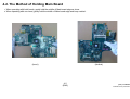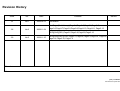
1
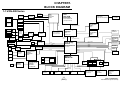
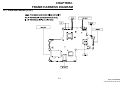
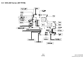
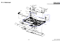
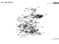
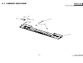
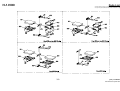
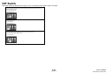
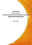
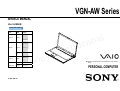
VGN-AW Series SERVICE MANUAL Ver.3-2008K Revision History Area Japanese Model Japanese US American European Canadian VGN-AW50DB/H VGN-AW70B/Q VGN-AW80NS* VGN-AW80S* VGN-AW80US* VGN-AW90NS VGN-AW90S VGN-AW90US VGN-AW110J/H VGN-AW110N/H VGN-AW120J/H VGN-AW125J/H VGN- AW130J/H VGN- AW150Y/H* VGN-AW160J/Q VGN-AW170C VGN-AW170Y/Q VGN-AW180Y/Q VGN-AW190 VGN-AW190C Latin VGN-AW110D VGN-AW120D VGN-AW180AU VGN-AW180FU AEP/UK VGN-AW1RXU/Q VGN-AW11M/H VGN-AW11S/B VGN-AW11SR/B VGN-AW11XU/Q VGN-AW11Z/B VGN-AW11ZR/B Asian/Oceania/ International South Africa Lineup Chinese VGN-AW15G/H VGN-AW17GU/Q ʳ VGN-AW19/Q ʳCTO Model 9-852-394-03 e d i f n o C y n o S l a i t n Design and specifications are subject to change without notice. PERSONAL COMPUTER Information in this document is subject to change without notice. Sony, VAIO and CLIE are trademarks or registered trademarks of Sony. Microsoft, Windows, Windows Media, Outlook, Bookshelf and other Microsoft products are trademarks or registered trademarks of Microsoft Corporation in the United States and other countries. The word Bluetooth and the Bluetooth logo are trademarks of Bluetooth SIG, Inc. AMD, the AMD logo, other AMD product names and combinations thereof are trademarks of Advanced Micro Devices, Inc. Intel Inside logo, Pentium, Celeron and Core are trademarks or registered trademarks of Intel Corporation. Transmeta, the Transmeta logo, Crusoe Processor, the Crusoe logo and combinations thereof are trademarks of Transmeta Corporation in the USA and other countries. Graffiti, HotSync, PalmModem, and Palm OS are registered trademarks, and the Hotsync logo and Palm are trademarks of Palm, Inc. or its subsidiaries. (M) and Motrola are trademarks of Motrora, Inc. Other Motrola products and services with (R) mark like Dragomball are the trademarks of Motrola, Inc. All other names of systems, products and services in this manual are trademarks or registered trademarks of their respective owners. In this manual, the (TM) or (R) mark are not specified. Caution Markings for Lithium/Ion Battery - The following or similar texts shall be provided on battery pack of equipment or in both the operating and the service instructions. Service and Inspection Precautions 1. Obey precautionary markings and instructions 4. Inspect after completing service Labels and stamps on the cabinet, chassis, and components identify areas requiring special precautions. Be sure to observe these precautions, as well as all precautions listed in the operating manual and other associated documents. After servicing, inspect to make sure that all screws, components, and wiring have been returned to their original condition. Also check the area around the repair location to ensure that repair work has caused no damage, and confirm safety. CAUTION: The battery pack used in this device may present a fire or chemical burn hazard if mis- 2. Use designated parts only 5. When replacing chip components... treated. Do not disassemble, heat above 60°C The set’s components possess important safety characteristics, such as noncombustibility and the ability to tolerate large voltages. Be sure that replacement parts possess the same safety characteristics as the originals. Also remember that the mark, which appears in circuit diagrams and parts lists, denotes components that have particularly important safety functions; be extra sure to use only the designated components. Never reuse components. Also remember that the negative side of tantalum capacitors is easily damaged by heat. CAUTION: Danger of explosion if battery is incorrectly replaced. Replace only with the same or equivalent type recommended by the manufacturer. Discard used batteries according to the manufacturer’s instructions. (140°F) or incinerate. Dispose of used battery promptly. Keep away from children. CAUTION: Changing the back up battery. • Overcharging, short circuiting, reverse charging, multilation or incineration of the cells must be avoided to prevent one or more of the following occurrences; release of toxic materials, release of hydrogen and/or oxygen gas, rise in surface temperature. • If a cell has leaked or vented, it should be replaced immediately while avoiding to touch it without any protection. 3. Always follow the original design when mounting parts and routing wires The original layout includes various safety features, such as inclusion of insulating materials (tubes and tape) and the mounting of parts above the printer board. In addition, internal wiring has been routed and clamped so as to keep it away from hot or high-voltage parts. When mounting parts or routing wires, therefore, be sure to duplicate the original layout. 7KH FRPSRQHQWV LGHQWLILHG E\ PDUN FRQWDLQ FRQ¿GHQWLDOLQIRUPDWLRQ 6WU LF WO\ IROORZ WKH LQVWU XF WLRQV ZKHQHYHU WKH FRPSRQHQWVDUHUHSDLUHGDQGRUUHSODFHG 2 6. When handling flexible print boards... • The temperature of the soldering-iron tip should be about 270°C. • Do not apply the tip more than three times to the same pattern. • Handle patterns with care; never apply force. Caution: Remember that hard disk drives are easily damaged by vibration. Always handle with care. [Sony Confidential] VGN-AW Series (9-852-394-XX) TABLE OF CONTENTS Section Title Page Section CHAPTER1. BLOCK DIAGRAM 1-1.VGN-AW Series………………………………………….. 1-1 (to 1-1) Title Page CHAPTER4. OTHERS 4-1.Replacing the CPU………………………………… 4-1 4-2. Holding Method of Main Board………………….. 4-2 (to 4-2) CHAPTER2. FRAME HARNESS DIAGRAM 2-1.VGN-AW Series (TOP)…………………………………… 2-1 2-2.VGN-AW Series (BOTTOM)…………………………….. 2-2 (to 2-2) CHAPTER3. EXPLODED VIEWS AND PARTS LIST Note……………………………………………………………. 3-2 Screws S-1.Screws……………………………………………… 3-3 Palmrest P-1.Palmrest………….………………………………… 3-4 Main Board M-1.Main Board ……………………………………….. 3-5 Bottom B-1.Bottom………….………………………………….. 3-6 CABINET KBCOVER C-1.CABINET KBCOVER…………………………….. 3-7 ODD D-1.ODD………………………………………………… 3-8 HDD H-1.HDD………………………………………………… 3-9 LCD L-1.LCD……………………………………………….… 3-10 ACCESSORIES A-1.ACCESSORIES…………………………………… 3-11 DIP Switch…………………………………………………….. 3-12 (to 3-12) x SPECIFICATIONS are listed on page 3-1 of “CHAPTER3. EXPLODED VIEWS AND PARTS LIST. x History of the changes is shown as the “Revision History” at the end of this data. 3 [Sony Confidential] VGN-AW Series (9-852-394-XX) CHAPTER1. BLOCK DIAGRAM 1-1.VGN-AW Series EEPROM (HDCP) HDMI Connector HDMI Connector nVIDIA NB9P/NB9M GDDR3 LVDS/VGA LVDS 18.4”’TFT SPDIF/HP CPU Intel C2D Processor GFX HDMI Clock Gen. ICS9LPR321AKLF(MLF64) X.TAL 14.318MHz Micro-FCBGA-478 (478 pin socket P) SPDIF /HP OUT Jack VGA D-type-15p PCIE X16 Ext.Mic in Jack USB 2.0 CONN*2 1 Watt (8 0hm) HDA 200pin R+ R- 1 Watt (8 0hm) 1 Watt (8 0hm) 2W AMP L+ YAMAHA YDA144B L- (R-ch) (L-ch) 1 Watt (8 0hm) SO-DIMM 0 667/800MHz DDR(II) FSB 667/800/1066MHz EQ Circuit R GDDR3 VRAM ALC889DSD CODEC L NB9P-GS 32Mx32bitx4 NB9M-GS 32Mx32bitx2 North Bridge Cantiga USB 2.0 CONN.X2 SO-DIMM 1 667/800MHz DDR(II) PM45 FCBGA-1329 200pin Express Card USB2.0 Sub Woofer 2 Watt (40)hm 2W AMP YDA153 X4 DMI (Direct Media Interface) Controller Link0 Mini-Card PCIE Digital Mic MDC1.5 Modem 12pin RJ11 HDA CAM (1.3M) PCIE JIMICRON JMB368 CF POWER SWITCHES BD2056AFJ SD PCIE FeliCa SATA 5 IR Receiver SATA 1 LPC Winbond WPCE775L Mini PCI (TV) F/PAL LQFP-128 SATA ODD Ethernet G-LAN 88E8055 MARVELL 10/100/1000 XBUS RJ45 Bluetooth SATA 0 B-CAS Transformer Netswap NS682403P USB2.0 SATA 4 RICOH R5C833 CardBus CardReader i-LINK I.LINK USB2.0 USB2.0 PCI BUS MS DUO ROBOSON 1.7 PCIE 676 mBGA USB2.0 Finger Print Sensor (UPEK) PCIE + USB2.0 South Bridge ICH9-M/ ICH9-Enhanced USB2.0 PWM PS/2 GPIO Expander W83L604G FAN Lid Switch & LED Touchpad 1-1 (END) Flash BIOS 1MB SMB Channel 1 SSD SSD HDD SATA HDD2 SATA HDD1 SMB Channel 2 BATT CONN Thermal Sensor EMC1402-2-ACZL (CPU/GMCH) Thermal Sensor G781P8f (VGA/DIMM) Thermal Sensor G709T1UF (H/W) uSOP8 [Sony Confidential] VGN-AW Series (9-852-394-XX) CHAPTER2. FRAME HARNESS DIAGRAM 2-1. VGN-AW Series (TOP) 2-1 [Sony Confidential] VGN-AW Series (9-852-394-XX) 2-2. VGN-AW Series (BOTTOM) 2-2 (END) [Sony Confidential] VGN-AW Series (9-852-394-XX) CHAPTER3. EXPLODED VIEWS AND PARTS LIST ΗThe parts list is compiled by blocks of a Palmrest and bottom etc. The sections of the parts list are different depending on the model. Please refer to list of contents shown. x Double-click on the paper clip mark in the Spec column to open the specifications list. x To open the parts list, Microsoft office Excel or Excel viewer is required. Section Page Note…………………………………………………………… 3-2 Screws S-1.Screws………………………………………………… Palmrest P-1.Palmrest………….…………………………………… Main Board M-1.Main Board …………………………………………… Bottom B-1.Bottom…………………………………………………. CABINET KBCOVER C-1.CABINET KBCOVER………………………………… 3-3 HDD H-1.HDD…………………………………………………….. LCD L-1.LCD…………………………………………………….. ACCESSORIES A-1.ACCESSORIES……………………………..………… DIP Switch……………………………..…………………… J 3-4 3-5 3-6 3-7 ODD D-1.ODD…………………………………………………… AW50DB/H AM 3-8 3-9 3-10 3-11 3-12 EU AO Palmrest Main Board Bottom ODD HDD LCD Accessories P-1 M-1 B-1 D-1 H-1 L-1 A-1 AW70B/Q P-1 M-1 B-1 D-1 H-1 L-1 A-1 AW80NSҘʽ P-1 M-1 B-1 D-1 H-1 L-1 A-1 AW80SҘʽ P-1 M-1 B-1 D-1 H-1 L-1 A-1 AW80USҘʽ P-1 M-1 B-1 D-1 H-1 L-1 A-1 AW90NS P-1 M-1 B-1 D-1 H-1 L-1 A-1 AW90S P-1 M-1 B-1 D-1 H-1 L-1 A-1 AW90US P-1 M-1 B-1 D-1 H-1 L-1 A-1 AW110D P-1 M-1 B-1 D-1 H-1 L-1 A-1 AW110J/H P-1 M-1 B-1 D-1 H-1 L-1 A-1 AW110N/H P-1 M-1 B-1 D-1 H-1 L-1 A-1 AW120D P-1 M-1 B-1 D-1 H-1 L-1 A-1 AW120J/H P-1 M-1 B-1 D-1 H-1 L-1 A-1 AW125J/H P-1 M-1 B-1 D-1 H-1 L-1 A-1 AW130J/H P-1 M-1 B-1 D-1 H-1 L-1 A-1 AW150Y/HҘ P-1 M-1 B-1 D-1 H-1 L-1 A-1 AW160J/Q P-1 M-1 B-1 D-1 H-1 L-1 A-1 AW170C P-1 M-1 B-1 D-1 H-1 L-1 A-1 AW170Y/Q P-1 M-1 B-1 D-1 H-1 L-1 A-1 AW80AU P-1 M-1 B-1 D-1 H-1 L-1 A-1 AW180FU P-1 M-1 B-1 D-1 H-1 L-1 A-1 AW180Y/Q P-1 M-1 B-1 D-1 H-1 L-1 A-1 AW190 P-1 M-1 B-1 D-1 H-1 L-1 A-1 A-1 AW190C P-1 M-1 B-1 D-1 H-1 L-1 AW1RXU/Q P-1 M-1 B-1 D-1 H-1 L-1 A-1 AW11M/H P-1 M-1 B-1 D-1 H-1 L-1 A-1 AW11S/B P-1 M-1 B-1 D-1 H-1 L-1 A-1 AW11SR/B P-1 M-1 B-1 D-1 H-1 L-1 A-1 AW11XU/Q P-1 M-1 B-1 D-1 H-1 L-1 A-1 AW11Z/B P-1 M-1 B-1 D-1 H-1 L-1 A-1 AW11ZR/B P-1 M-2 B-1 D-1 H-1 L-1 A-1 AW15G/H P-1 M-1 B-1 D-1 H-1 L-1 A-1 AW17GU/Q P-1 M-1 B-1 D-1 H-1 L-1 A-1 AW19/Q P-1 M-1 B-1 D-1 H-1 L-1 A-1 Spec CTO Model 3-1 [Sony Confidential] VGN-AW Series (9-852-394-XX) Note x If there is the Remarks column in the parts list, the features of applicable models are indicated in it for the parts that are different depending on each model. For the abbreviations used in the remarks column, please refer to the <table 1>. xParts List is attached on the upper right portion of each EXPLODED VIEW. x Items marked “*” are not stocked since they are seldom required for routine service. Some delay should be anticipated when ordering these items. xThe mechanical parts with no reference number in the exploded views are not supplied. xThe parts marks “$” are the Reuse Parts. xThe parts marks with “&” indicates specific parts handling for Japan region. Disregard “&” marking for other than Japan region. x Color after description in [ ] shows color variation name of the main body. x The model that is accompanied by asterisk () is the CTO model. xWhen replacing the HDD of RAID setting, please exchange to the same HDD that was installed. <table 1> Full-Name Bluetooth Felica Wireless WAN Wireless LAN 1seg Tuner Finger Print Sensor Security Chip Flash Memory Camera Basically, the parts marked “z” should be used for service. The parts marked “” in the parts list are substitution parts. If the part marked “z” is not available, you can order the parts marked “”, but it may not be stocked. Short-Name BT Felica WAN WLAN 1seg FP TPM F Mem Camera x If “No-” is described on the left side of the Short-Name, it means ‘not equipped’. Example: “No-BT” “No-Felica” etc. x When several descriptions are listed, each description is separated with “, (comma)” or “or”. “Comma” means plus. Example.1: The parts for the model equipped with BT and Felica and WLAN ÆBT, Felica, WLAN Example.2: The parts for the model equipped with BT or Felica ÆBT or Felica x If the color is in the remarks column, it indicates the color of parts itself. 3-2 [Sony Confidential] VGN-AW Series (9-852-394-XX) S-1. SCREWS Parts List x Double-click on the paper clip mark to open the parts list. x To open the parts list, Microsoft office Excel or Excel viewer is required. B1 M2*L2.5 Silver B2 B3 M2.6*L9 M2*L3 Silver Black B4 B5 B6 M2*L5 M2*L8 Silver Silver 3-3 M2*L8 Black B7 M2*L1.6 Black B8 B9 B10 M3*L3 M3*L6 M3*L8 Silver Black Black [Sony Confidential] VGN-AW Series (9-852-394-XX) P-1. Palmrest Parts List x Double-click on the paper clip mark to open the parts list. x To open the parts list, Microsoft office Excel or Excel viewer is required. B5 27 B3 24 B5 26 28 27 6 10 26 B4 22 28 37 B3 12 15 B3 16 23 38 14 9 13 25 B3 31 33 5 B3 17 3 20 36 1 B3 19 7 35 39 8 21 B3 11 18 4 2 B3 3-4 [Sony Confidential] VGN-AW Series (9-852-394-XX) M-1. Main Board Parts List x Double-click on the paper clip mark to open the parts list. x To open the parts list, Microsoft office Excel or Excel viewer is required. 3-5 [Sony Confidential] VGN-AW Series (9-852-394-XX) B-1.Bottom Parts List • Double-click on the paper clip mark to open the parts list. • To open the parts list, Microsoft office Excel or Excel viewer is required. 3-6 [Sony Confidential] VGN-AW Series (9-852-394-XX) C-1. CABINET KBCOVER Parts List x Double-click on the paper clip mark to open the parts list. x To open the parts list, Microsoft office Excel or Excel viewer is required. B7 702 703 704 706 705 B7 701 3-7 [Sony Confidential] VGN-AW Series (9-852-394-XX) D-1.ODD Parts List x Double-click on the paper clip mark to open the parts list. x To open the parts list, Microsoft office Excel or Excel viewer is required. 3-8 [Sony Confidential] VGN-AW Series (9-852-394-XX) H-1.HDD Parts List x Double-clickon the paper clip markto open the parts list. x To open the parts list, Microsoft office Ex cel or Ex cel ivewer is req uired. 3-9 [Sony Confidential] VGN-AW Series (9-852-394-XX) L-1.LCD Parts List x Double-click on the paper clip mark to open the parts list. x To open the parts list, Microsoft office Excel or Excel viewer is required. 3-10 [Sony Confidential] VGN-AW Series (9-852-394-XX) A-1. ACCESSORIES Parts List x Double-click on the paper clip mark to open the parts list. x To open the parts list, Microsoft office Excel or Excel viewer is required. 2005 POWER CORD 2007 Battery Pack 2006 AC ADAPTER 2013 RF Cable 2014 REMOTE CONTROLLER 3-11 [Sony Confidential] VGN-AW Series (9-852-394-XX) DIP Switch DIP switch setting is different by the type of LCD. For setting method, please refer to the table. VGN-AW70B/AW80NS/AW80S/AW80USAW90NS/AW90S/AW90US (J) VGN-AW150Y/AW160J/AW170C/AW170Y/AW180AU/AW180FU/AW180Y/AW190/AW190C (AM) VGN-AW1RXU/AW11XU (EU) VGN-AW17GU/AW19 (AO) 18.4 TFT (Samsung) VGN-AW110D/AW110J/AW110N/AW150Y˂AW190/AW190C (AM) VGN-AW11M/AW (EU) VGN-AW15G (AO) 18.4 TFT (Samsung) VGN-AW50DB/ AW80NS/AW80S/AW80USAW90NS/AW90S/AW90US (J) VGN-AW120D/AW120J/AW125J/AW130J/ AW150Y/AW190/AW190C (AM) VGN-AW11S/AW11SR/AW11Z/AW11ZR (EU) 18.4 TFT (Samsung) 3-12 (END) [Sony Confidential] VGN-AW Series (9-852-394-XX) CHAPTER 4. OTHERS 4-1.Replacing the CPU 1. Removing the CPU 1. Insert a flat-blade screwdriver into the notch as shown illustration and rotate it so that the protrusion comes to the 2. Installing the CPU 1. Align the triangle reference mark of the mark the CPU with that of the CPU lock release position. 2. Pull the CPU gently upward to lift it out of the CPU socket socket and insert all the pins of the CPU to the corresponding holes of the CPU socket. 2. Insert the flat head (-) screwdriver into the specified position and rotate th screwdriver to the LOCK position. 1 1 Unlock Lock 2 2 Reference marks 2 Unlock Lock 1 4-1 [Sony Confidential] VGN-AW Series (9-852-394-XX) 4-2. The Method of Holding Main Board 1. When operating with both hands, gently hold the middle of Main board edge as show. 2. When operating with one-hand, gently hold the middle of Main board edge and keep vertical. (Level) (Vertical) 4-2 (END) [Sony Confidential] VGN-AW Series (9-852-394-XX) VGN-AW Series (J/AM/EU/AO) This manual and the constituent data may not be replicated, copied nor reprinted in whole or in part without prior written authorization of Sony Corporation 9-852-394-03 Sony Corporation 21 English 2008KF00-1 © 2008 Sony Corporation Published by Sony Corporation VAIO Business Group VAIO Global CS Dept. Revision History Suffix Ver. Date -01 Ver.1 2008.09.12 -02 Ver.2 2008.11.04 Contents QM No. First Edition First Page (ModelLineup),Page3-1,Page3-3,Page3-4,Page3-5, Page3-6,Page3-7,Page3-8,Page3-9,Page3-10, Page3-11, Page3-12 [ADD][CHG][DEL] Page3-5,Page3-6,Page3-9,Page3-10 -03 Ver.3 2008.11.25 [ADD][CHG][DEL][COR] Page3-1,Page3-4,Page3-5,Page3-6, Page3-8, Page3-9, Page3-10, Page3-11 <Remarks> 324 [Sony Confidential] VGN-AW Series (9-852-394-XX)