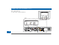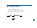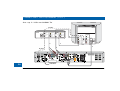
1
DOLBY
Manufactured under license from Dolby Laboratories.
“Dolby” and the double-D symbol are trademarks of
Dolby Laboratories. Confidential Unpublished Works.
©1992-1997 Dolby Laboratories, Inc. All rights reserved.
This product incorporates copyright protection technology that is protected by
U.S. patents and other intellectual property rights. Use of this copyright protection
technology must be authorized by Macrovision, and is intended for home and other
limited pay-per-view uses only unless otherwise authorized by Macrovision.
Reverse engineering or disassembly is prohibited.
Pace and
are trademarks and/or registered trademarks of
Pace Micro Technology plc.
HDMI, the HDMI logo and High-Definition Multimedia Interface are trademarks or
registered trademarks of HDMI Licensing LLC.
Other trademarks listed herein are the property of their respective owners.
The model and serial number of the Pace TDC775D are on a label on
its base.
Copyright © 2005 Pace Micro Technology plc All rights reserved
CONTENTS
SAFETY INFORMATION . . . . . . . . . . . . . . . . . . . . . . . . . . . . 2
IMPORTANT SAFETY INSTRUCTIONS . . . . . . . . . . . . . . . . 3
OVERVIEW . . . . . . . . . . . . . . . . . . . . . . . . . . . . . . . . . . . . . . . 8
FRONT PANEL . . . . . . . . . . . . . . . . . . . . . . . . . . . . . . . . . . . . 9
REAR PANEL . . . . . . . . . . . . . . . . . . . . . . . . . . . . . . . . . . . . 10
GETTING THE CABLES READY . . . . . . . . . . . . . . . . . . . . . 12
CONNECTING A VCR CONTROLLER (IR transmitter) . . 13
CONNECTING A REMOTE EYE (IR receiver) . . . . . . . . . . 14
CONNECTING THE EQUIPMENT . . . . . . . . . . . . . . . . . . . 15
Activating baseband loopthrough for a DVD
or similar equipment . . . . . . . . . . . . . . . . . . . . . . . . . . . . 15
Set-up A: HDMI TV (+ optional home theater) . . . . . . . 16
Set-up B: DVI TV (+ optional home theater) . . . . . . . . . 18
Set-up C: VCR and HDMI TV . . . . . . . . . . . . . . . . . . . . . 20
Set-up D: VCR, Home Theater and HDMI TV . . . . . . . . 23
Set-up E: DVD and HDMI TV . . . . . . . . . . . . . . . . . . . . . 25
Set-up F: VCR, DVD, Home Theater and HDMI TV . . . 27
Set-up G: Component-video HDTV
(+ optional home theater) . . . . . . . . . . . . . . . . . . . . . . . . 29
Set-up H: DVD and Component-video HDTV
(+ optional home theater) . . . . . . . . . . . . . . . . . . . . . . . . 31
Set-up I: VCR, DVD, Home Theater and
Component-video HDTV . . . . . . . . . . . . . . . . . . . . . . . . 34
CONNECTING TO THE AC POWER SUPPLY . . . . . . . .
Connecting the TV to the AC power supply . . . . . . . . .
Connecting the power cord to the set-top . . . . . . . . . .
Connecting equipment to the AC wall outlets . . . . . . .
TURNING ON AND TUNING IN . . . . . . . . . . . . . . . . . . .
Turning the set-top on and off . . . . . . . . . . . . . . . . . . . .
Tuning the TV and VCR to the set-top . . . . . . . . . . . . . .
RF BYPASS . . . . . . . . . . . . . . . . . . . . . . . . . . . . . . . . . . . . . .
TDC775D DVR FUNCTIONS . . . . . . . . . . . . . . . . . . . . . . .
MAKING HDTV-DISPLAY SETTINGS . . . . . . . . . . . . . . . .
USING THE SETUP MENUS . . . . . . . . . . . . . . . . . . . . . . . .
SOLVING PROBLEMS . . . . . . . . . . . . . . . . . . . . . . . . . . . . .
Apparent “problems” that may be caused
by certain menu settings . . . . . . . . . . . . . . . . . . . . . . . . .
36
37
37
37
38
38
38
40
42
43
57
58
61
To enhance the set-top, the on-screen menus may be updated
from time to time, over the cable. They may therefore differ
from those shown in this manual.
The latest issue of this manual, with related information, is
available on the Pace website at:
www.pacemicro.com/manuals.asp
1
SAFETY INFORMATION
This digital set-top has been manufactured and tested with your
safety in mind. However, improper use can result in potential
electric shock or fire hazards. To avoid defeating the safeguards that
have been built into the set-top, please observe the precautions
discussed in this document.
Warnings on the set-top
CAUTION
ATTENTION
RISK OF ELECTRIC SHOCK
DO NOT OPEN
RISQUE DE CHOC ELECTRIQUE
NE PAS OUVRIR
Other warnings
TO REDUCE THE RISK OF ELECTRIC SHOCK, DO NOT REMOVE THE
COVER OF THE SET-TOP.
THERE ARE NO USER-SERVICEABLE PARTS INSIDE IT.
TO REDUCE THE RISK OF FIRE OR ELECTRIC SHOCK, DO NOT
EXPOSE THIS SET-TOP TO RAIN OR MOISTURE.
DO NOT PERFORM ANY SERVICING UNLESS YOU ARE QUALIFIED TO
DO SO. REFER ALL SERVICING TO QUALIFIED SERVICE PERSONNEL.
SERVICING THE SET-TOP YOURSELF WILL INVALIDATE THE WARRANTY.
Installation
The installation of the set-top should be carried out by a qualified
installer and should conform to local codes.
The lightning flash with arrowhead symbol,
within a triangle, is intended to alert you to the
presence of uninsulated “dangerous” voltages
within the set-top’s enclosure that may be of
sufficient magnitude to constitute a risk of
electric shock to persons.
2
The exclamation point within a triangle is
intended to alert you to the presence of
important instructions in the literature
accompanying the set-top.
Note to the installer
This reminder is provided to call the attention of the cable-TV-system
installer to Section 820-40 of the National Electrical Code (USA),
which provides guidelines for proper grounding and, in particular,
specifies that the cable ground shall be connected to the grounding
system of the building, as close to the point of cable entry as is practical.
Service address:
Pace Micro Technology (Support Services) Ltd.
3701 FAU Boulevard, Suite 200
Boca Raton
Florida, 33431, U.S.A.
IMPORTANT SAFETY INSTRUCTIONS
Before you install or use the apparatus, you must read
and understand these Important Safety Instructions.
At all times when using the apparatus you must follow
these Important Safety Instructions to reduce the risk of
fire, electrical shock and injury to persons.
10. Protect the power cord from being walked on or pinched
particularly at plugs, convenience receptacles, and the point
where they exit from the apparatus.
1. Read these instructions.
12. Use only with the cart, stand, tripod, bracket, or table
specified by the manufacturer, or sold with the apparatus.
When a cart is used, use caution when moving the cart/
apparatus combination to avoid injury from tip-over.
2. Keep these instructions.
3. Heed all warnings.
11. Only use attachments/accessories specified by the
manufacturer.
4. Follow all instructions.
5. Do not use this apparatus near water.
6. Clean only with dry cloth.
7. Do not block any ventilation openings. Install in accordance
with the manufacturer’s instructions.
8. Do not install near any heat sources such as radiators, heat
registers, stoves, or other apparatus (including amplifiers)
that produce heat.
9. Do not defeat the safety purpose of the polarized or
grounding-type plug. A polarized plug has two blades with
one wider than the other. A grounding type plug has two
blades and a third grounding prong. The wide blade or the
third prong are provided for your safety. If the provided plug
does not fit into your outlet, consult an electrician for
replacement of the obsolete outlet.
13. Unplug this apparatus during lightning storms or when
unused for long periods of time.
14. Refer all servicing to qualified service personnel. Servicing is
required when the apparatus has been damaged in any way,
such as power-supply cord or plug is damaged, liquid has
been spilled or objects have fallen into the apparatus, the
apparatus has been exposed to rain or moisture, does not
operate normally, or has been dropped.
3
SAFETY INFORMATION (cont.)
In addition to the Important Safety Instructions, please read the
Safety Information below.
Power sources
You must operate the set-top only from the type of power source
indicated on the marking label. If you are not sure of the type of power
supply to the home, consult the dealer or local power company.
Overloading
Do not overload wall outlets, extension cords or other power
outlets as this can result in a risk of fire or electric shock.
Lightning
For added protection for the set-top during a lightning storm, or
when it is left unattended and unused for long periods of time,
disconnect the antenna, cable system and telecommunication line
cord from the set-top. See also item 13 in the Important Safety
Instructions.
Placement and mounting
Do not place the set-top on an unstable or uneven surface. The settop may fall, causing serious injury to a child or adult and serious
damage to the set-top. If you mount the set-top, for example to a
wall or ceiling, follow the manufacturer’s instructions and use a
mounting accessory recommended by the manufacturer. See also
item 12 in the Important Safety Instructions.
4
Ventilation
Slots and openings in the casing of the set-top are provided for
ventilation, to ensure reliable operation of the set-top and to
protect it from overheating.
• never block the ventilation openings by placing the set-top on a
bed, sofa, rug or other similar surface;
• never cover the ventilation openings with items such as
newspapers, table-cloths or curtains;
• do not place the set-top in a built-in installation such as a
bookcase or rack unless proper ventilation is provided or you
have adhered to the manufacturer’s instructions;
• maintain a minimum distance of 3 inches around the set-top
for sufficient ventilation.
See also item 7 in the Important Safety Instructions.
Water and moisture
Do not expose this set-top to dripping or splashing and ensure that
no objects filled with liquids, such as vases, are placed on the settop. See also item 5 in the Important Safety Instructions.
Entry of objects and liquids
Never push objects of any kind into the set-top through openings
as they may touch dangerous voltage points or short-out parts that
could result in fire or electric shock. Never spill liquid of any kind on
the set-top.
SAFETY INFORMATION (cont.)
Risk of fire or scorching
Never place naked flame sources, such as lighted candles, on the
set-top.
Outdoor antenna grounding
Be sure that any outside antenna or cable system connected to the
set-top is grounded so as to provide some protection against
voltage surges and static charges that have built up. Article 810 of
the National Electrical Code (USA), ANSI/NFPA 70 provides
information with regard to proper grounding of the mast and
supporting structure, grounding of the lead-in wire to an antennadischarge unit, size of grounding conductors, location of antennadischarge unit, connection to grounding electrodes and
requirements for the grounding electrode. See the diagram below.
(Example antenna grounding as per
National Electrical Code, ANSI/NFPA 70)
antenna lead-in wire
ground clamps
antenna-discharge unit
(NEC section 810-20)
electric service equipment
ground clamps
grounding conductors
(NEC section 810-21)
power service grounding electrode system
(NEC ART 250, PART H)
Power lines
You must not locate an outside antenna system in the vicinity of
overhead power lines or other electric light or power circuits, or where
it can fall into such power lines or circuits. When installing an outside
antenna system, you must take extreme care to avoid touching such
power lines or circuits, as contact with them might be fatal.
Transporting
Move the combination of set-top and cart with care. Quick stops,
excessive force and uneven surfaces may cause the combination of
set-top and cart to overturn. See also item 12 in the Important
Safety Instructions.
Ambient temperature
The operating temperature range of the set-top is 32-104°F. If the
ambient temperature around the set-top falls outside this range,
you must correct this in order for the set-top to work correctly and
safely. For example, if the temperature is too high, switch on the air
conditioning.
Replacement parts
When replacement parts are required, be sure that the service
technician has used replacement parts specified by the
manufacturer or that have the same characteristics as the original
part. Unauthorized substitutions may result in fire, electric shock or
other hazards. See also item 14 in the Important Safety Instructions.
5
SAFETY INFORMATION (cont.)
Safety check
Upon completion of any servicing or repairs to the set-top, ask the
service technician to perform safety checks to determine that the
set-top is in its proper operating condition. See also item 14 in the
Important Safety Instructions.
SAVE THIS INFORMATION FOR FUTURE REFERENCE
The POWER OUTLET plug is designed only for connection to the AC
power cord for a TV. The maximum power it can supply is 500 watts.
Do not connect any equipment that uses more than 500 watts, or any
non-TV equipment such as a toaster or hair drier.
Safety aspects of connections
Full details of the rear panel are on page 10.
Connecting
Do not connect the set-top (or any other equipment such as a TV
or VCR) to the power supply until you have properly connected all
the other cables.
The set-top operates with a 120 V AC, 60 Hz power supply. Do
not connect the set-top to any supply other than this.
This set-top is equipped with a two-wire power cord, with a
polarized plug at one end. The other end of the cord is fitted with
a polarized connector, which is shaped such that it can only be fitted
one way into the power input jack of the set-top. Connect this end
first, before inserting the polarized plug into the wall socket-outlet.
Disconnecting
Disconnect the set-top from the power supply before you
disconnect any other equipment from its rear panel.
6
The CABLE IN connector is designed for
connection to a cable network only.
You must not connect any other equipment,
such as a VCR, to this input.
The only way to disconnect the set-top from the power supply is
to remove the power cord from the wall socket-outlet. The set-top
must therefore be installed near to the wall socket-outlet, which
should be easily accessible.
POWER INPUT
SAFETY INFORMATION (cont.)
Epilepsy and on-screen images
Regulatory information
Certain people are susceptible to epileptic seizures or losing
consciousness when faced with certain types of flashing lights in our
daily environment.
These people are exposed to the risk of seizures if they watch
certain television images or if they view certain images while they
are browsing the Web. These phenomena may appear even when
the subject has no previous history of this problem or has never
suffered an epileptic seizure.
If you, or a member of the family, has already suffered symptoms
linked to epilepsy (seizure or loss of consciousness) in the presence
of stimulation by light, please consult the doctor before using this
product.
If you or any person using the equipment experiences dizziness,
involuntary movements or convulsion, please immediately stop
viewing and consult a doctor.
When you are browsing the Web or playing a Web-based game,
take the following precautions:
• Use the equipment in a well-lit room, and turn down the
brightness of the television screen.
• Sit at a reasonable distance from the television screen.
• Take a break for ten minutes every hour.
You should avoid using the Web if you are tired or have lost some
sleep.
CAUTION: Do not attempt to modify the set-top without
written authorization from the manufacturer. Unauthorized
modification could void your authority to operate the set-top.
NOTE
The set-top has been tested and found to comply with the limits for a
Class B digital device, pursuant to Part 15 of the FCC Rules. These
limits are designed to provide reasonable protection against harmful
interference in a residential installation. The set-top generates, uses
and can radiate radio-frequency energy and, if not installed and used in
accordance with the instructions, may cause harmful interference to
radio communications.
However, there is no guarantee that interference will not occur in a
particular installation. If the set-top does cause harmful interference to
radio or television reception, which can be determined by turning the
set-top off and on, you are encouraged to try to correct the
interference by one or more of the following measures:
• Reorient or relocate the receiving antenna.
• Increase the separation between the set-top and the receiver.
• Connect the set-top to an outlet on a circuit different from that to
which the receiver is connected.
• Consult the dealer or an experienced radio/TV technician for help.
7
OVERVIEW
• Read all the safety information on page 2 through 7.
• Familiarize yourself with the front and rear panels of the set-top (see page 9
and page 10).
• Do you want to control a VCR from the set-top? If so, connect a VCR
controller (IR transmitter) (see page 13).
• Is the set-top in a TV cabinet with closed non-transparent doors or
somewhere else where its IR-receive window is blocked from view? If so,
connect a remote eye (IR receiver) (see page 14).
• Decide how you want to connect the set-top (and to which equipment) and
look at the table (right) to see which set-up you should use.
Using the TV’s HDMI connector:
HDMI TV (+ optional home theater
receiver)
Set-up A
DVI HDTV (+ optional home theater
receiver)
Set-up B
VCR and HDMI TV
Set-up C
VCR, home theater receiver and HDMI TV
Set-up D
DVD player and HDMI TV
Set-up E
VCR, DVD player, home theater receiver
and HDMI TV
Set-up F
• Be aware of menu settings that could affect your choice of set-up (see page 57).
• Connect the equipment together according to your chosen set-up, but do not
yet connect the power cords (see page 15 through 35).
• Connect the power cords and turn on the equipment (see page 36 through
38).
• Check that you can see a picture on the TV and do any necessary tuning (see
page 38).
• Check whether the HDTV-display settings are appropriate for the TV being
used and change them if necessary (see page 44 through 54).
• Any problems? Consult the “Solving Problems” section on page 58.
8
Using the TV’s component video and stereo
audio connectors:
HDTV (+ optional home theater receiver)
Set-up G
DVD player and HDTV
(+ optional home theater receiver)
Set-up H
VCR, DVD player, home theater receiver
and HDTV
Set-up I
FRONT PANEL
menu channel U and D
To display on-screen menus To change channel up or
bypass down
To turn the RF bypass feature on/off
guide
To display an on-screen guide
smart-card slot
info
For future use
To display on-screen information
power button
To turn the set-top on/off
power light
(beside button)
Lights blue when the set-top is
on; red when the set-top is in
standby; off when the set-top is
off
front-panel display
Appears when the set-top is
turned on
Shows the program channel
number or the time
Also used to display HDTV
settings (see page 43)
play/record lights
Indicate the play and record
state of each display channel
Lights green to signify
playback; red to signify
record
Lights when the set-top is receiving a signal Lights when there is an unread message
from the remote control
Lights when the set-top outputs High Lights while the bypass feature is on
Definition Television (HDTV) content
L, R, U and D
To move left/right/up/
down in an on-screen
menu/guide
select button
To select items in
menus/guides
VIDEO IN; AUDIO
IN L AND R
Baseband inputs – for
future use
USB connector
– for future use
Lights when the set-top receives Lights if the current program has a special
multi-channel sound broadcast security flag
9
REAR PANEL
COMPONENT
VIDEO OUT
Component video output
for analog HDTV
AUDIO IN
Audio baseband input
(stereo, L and R)
SECONDARY
AUDIO OUT
Audio baseband outputs
(stereo, L and R)
S-VIDEO
S-video output
COMPONENT
VIDEO IN
Component analog
video input
TO TV
RF output to the
TV or VCR
10
CABLE IN
From cable
service-provider
PRIMARY
AUDIO OUT
Audio baseband outputs
(stereo, L and R)
IR RECEIVE
Infra-red input from
a remote “eye”
TV PASS MODULE
Connector for a TV pass®
module (for installer’s use only)
IR TRANSMIT
Infra-red output
to control a VCR
VIDEO IN
Video baseband
input
VIDEO OUT
Video baseband
output
1394
For connection
to a 1394compatible
device
SATA
For connection
to an external
hard drive
HDMI
Video and audio
output for digital HDTV
UNIVERSAL
SERIAL BUS (USB)
For future use
ETHERNET
For future use
DIGITAL AUDIO OUT
Electrical S/PDIF audio output
DIGITAL AUDIO IN
Electrical S/PDIF audio input
POWER OUTLET
(500 W max.)
POWER INPUT
(Make this connection last of all)
OPTICAL AUDIO IN
Optical S/PDIF audio input
OPTICAL AUDIO OUT
Optical S/PDIF audio output
REAR PANEL (cont.)
CABLE IN
Connect the cable service here.
TO TV
Connect to the RF/antenna input on a TV or VCR.
COMPONENT
VIDEO OUT
If the HDTV does not have an HDMI (see
below), connect the HDTV here.
COMPONENT
VIDEO IN
Connect equipment such as a DVD player, if it has
component video jacks.
TV PASS MODULE
Connect a TV pass® module, if required.
PRIMARY AUDIO
OUT
Connect to the stereo audio inputs on a stereo
TV, stereo VCR or optional stereo amplifier.
IR TRANSMIT
Connect to an optional VCR controller.
IR RECEIVE
Connect to an optional “remote eye”.
S-VIDEO
Connect to the S-video baseband input (if
present) on a VCR or TV.
SECONDARY AUDIO Connect to the stereo audio inputs on a
secondary TV, VCR or optional stereo amplifier
OUT
AUDIO IN
VIDEO OUT
VIDEO IN
Connect to the stereo audio outputs on a DVD
player (or similar).
USB
(UNIVERSAL
SERIAL BUS)
Connect to compatible optional equipment that
supports a USB 1.1 interface, for example: a
printer, digital camera, keyboard or mouse.
ETHERNET
Connect to an optional PC network.
HDMI
(HIGH DEFINITION
MULTIMEDIA
INTERFACE)
If the HDTV has an HDMI, connect it here for a
digital audio/video connection (instead of using
the AUDIO and 3 analog COMPONENT
VIDEO connectors).
1394
Connect to a 1394-compatible device.
SATA
Connect to an optional external hard drive.
DIGITAL AUDIO
OUT
Connect to the electrical digital audio input on
optional digital audio equipment, such as an audio
decoder or home theater receiver.
OPTICAL AUDIO
OUT
Connect to the optical digital audio input on
optional digital audio equipment.
DIGITAL AUDIO IN
Connect to any electrical digital audio output
that loops through the set-top.
OPTICAL AUDIO IN Connect to any optical digital audio output that
loops through the set-top
Connect to the video baseband input on a VCR
(or a standard TV).
POWER OUTLET
Connect to the video baseband output on a DVD
player (or similar).
Connect the TV’s power cord here to provide AC
power to a TV.
POWER INPUT
Connect the set-top’s power cord here.
11
GETTING THE CABLES READY
Below is a list of cables (and their connectors) that are shown in the diagrams on page 13 through
34, along with a key to how they are depicted in the diagrams. (Options are shown as dashed lines.)
Cable type
Connector type
75 Ω coaxial
male F-type
HDMI
HDMI 19-pin type A
1
HDMI (to DVI)
HDMI 19-pin type A
2
Component video 75 Ω coax male RCA jack
12
Cable numbers
Drawn as
9, 12
Video 75 Ω coaxial
male RCA jack
S-video
4-way male mini-DIN
Stereo audio coaxial
male RCA jack
3, 6, 7, 10
75 Ω digital audio coaxial*
male RCA jack
8, 11
Digital audio optical
Optical S/PDIF
VCR controller
male 3.5 mm jack
IR receive
male 3.5 mm jack
USB
USB 1.1 series A plug
4, 5
* Any cable connected to DIGITAL AUDIO IN or DIGITAL AUDIO OUT must be 75 Ω coaxial, not regular audio cable.
CONNECTING A VCR CONTROLLER (IR transmitter)
You can control a VCR by connecting a VCR controller (IR transmitter) to the rear panel of the settop. As an example, if you set up timers in the set-top (to switch to specific programs at set times),
the emitter on the VCR controller will cause the VCR to record at those times.
The Pace VCR controller for use with this set-top is not supplied with the set-top. Contact the cable
operator for details. It has an emitter that is designed to stick near to the remote-control sensor of
the VCR it controls.
Installing the VCR controller
1. Refer to the VCR’s user guide to find out where its remote-control sensor is. (This is also known
as the IR or infrared sensor.)
2. Select a location on the VCR to attach the IR emitter. This must be within 3 inches of the
remote-control sensor. Make sure the area is clean and dry.
3. Remove the covering from the adhesive strip on the IR emitter.
4. Making sure the round end points towards the remote-control sensor, stick the emitter onto the
VCR.
5. Insert the 3.5 mm jack plug on the other end of the VCR controller into the socket labeled
“IR TRANSMIT” on the rear panel of the set-top.
6. You must then use the on-screen menus to set up the set-top to recognize the brand of VCR
that is being used. Consult the instructions for the on-screen menus and the instructions for the
VCR controller for further details on how to do this.
VCR
IR emitter
remote-control sensor
(the position of this will vary according
to the brand and model of VCR)
3.5 mm jack plug
IR emitter
adhesive strip
3.5 mm jack plug
13
CONNECTING A REMOTE EYE (IR receiver)
You may need to install the set-top in an equipment closet with closed non-transparent doors or
some other location where the remote-control sensor (IR-receive window) on the set-top’s front
panel is blocked from view (for example, if the TV is wall-mounted). In that case, you need to connect
a remote eye (IR receiver) to the set-top’s rear panel. The IR signals from the remote control can be
received by the remote eye and they then reach the set-top through the remote eye’s cable. This is
not supplied with the set-top.
1. Select a location for the remote eye. This will typically be on the top or side of the TV, but could
be in a different, but convenient, location. Make sure that it is in a position where there is a clear
path between the remote control and the remote eye.
2. Make sure that you can conveniently route the cable. The cable on the remote eye is
approximately 10 feet long, so make sure that the location you have chosen is within 10 feet of
the IR RECEIVE jack on the set-top’s rear panel.
3. Make sure the area where you will attach it is clean and dry.
4. A small adhesive patch is supplied with the remote eye. Remove the paper from one side of the
patch and stick the patch to the back (larger, flat side) of the remote eye.
5. Remove the paper from the other side of the adhesive patch and stick the remote eye at the
position you want. Make sure that the window at the curved end of the remote eye points
towards the position from which the remote control will be operated.
6. Insert the 3.5 mm jack plug on the other end of the remote eye’s cable into the socket labeled
“IR RECEIVE” on the rear panel of the set-top.
front of
HDTV
remote
eye
adhesive patch
3.5 mm jack plug
remote eye
14
CONNECTING THE EQUIPMENT
On the following pages are diagrams that show you how to connect typical
equipment (HDTV, VCR, DVD player and home theater receiver) to the set-top.
The connected items are shown individually and then in combination (see the
tables, right). Some of the connections may change when extra equipment is
added. For example, when a you add a home theater receiver, some cables that
previously went to the TV can, instead, go to the home theater receiver.
Activating baseband loopthrough for a
DVD or similar equipment
To activate baseband loopthrough, simply put the set-top into standby by pressing
the POWER button on the remote (making sure the remote control is set to
control the set-top) or by pressing the power button on the front panel. When
the set-top is in standby, the light beside the power button is red.
Using the TV’s HDMI connector:
HDMI TV (+ optional home theater
receiver)
Set-up A
DVI HDTV (+ optional home theater
receiver)
Set-up B
VCR and HDMI TV
Set-up C
VCR, home theater receiver and HDMI TV
Set-up D
DVD player and HDMI TV
Set-up E
VCR, DVD player, home theater receiver
and HDMI TV
Set-up F
If you activate baseband loopthrough, the following occur:
COMPONENT VIDEO IN
loops to
COMPONENT VIDEO OUT
VIDEO IN
loops to
VIDEO OUT
AUDIO IN
loops to
PRIMARY AUDIO OUT and
SECONDARY AUDIO OUT
DIGITAL AUDIO IN
loops to
DIGITAL AUDIO OUT
OPTICAL AUDIO IN
loops to
OPTICAL AUDIO OUT
Using the TV’s component video and stereo
audio connectors:
HDTV (+ optional home theater receiver)
Set-up G
DVD player and HDTV
(+ optional home theater receiver)
Set-up H
VCR, DVD player, home theater receiver
and HDTV
Set-up I
15
CONNECTING THE EQUIPMENT (cont.)
Set-up A: HDMI TV
(+ optional home theater)
HDTV
COMPONENT
VIDEO IN
Y IN
RF CABLE
PB/CB IN
S-VIDEO
IN
HDMI
ANTENNA/
RF IN
HOME THEATER
RECEIVER
POWER
VCR IN
VIDEO IN
LEFT
AUDIO IN
COAXIAL
AUDIO IN
POWER
LEFT
AUDIO IN
LEFT
AUDIO IN
RIGHT
AUDIO IN
RIGHT
AUDIO IN
OPTICAL
AUDIO IN
1
8
CABLE INPUT
VIDEO IN
DIGITAL AUDIO IN
RIGHT
AUDIO IN
16
PR/CR IN
CONNECTING THE EQUIPMENT (cont.)
About Set-up A: Using an HDMI cable to connect a TV
(optional home theater shown)
This is the most basic set-up, with only an HDTV and optional home theater connected.
• The set-top has a high-definition multimedia interface (HDMI) connector.
• The HDTV has an HDMI, so use an HDMI cable (1) to connect it to the set-top’s HDMI.
HDMI carries both high-resolution digital video and digital audio.
• To enhance the sound, you can connect a home theater receiver.
• There is a choice of two S/PDIF outputs: (i) electrical (labeled DIGITAL AUDIO OUT, which is
shown connected by cable 8 in the diagram, opposite) and (ii) optical (labeled OPTICAL
AUDIO OUT).
• When you add a home theater receiver, the set-top’s audio connection to the TV (via HDMI) is
not needed, so you may wish to mute (turn off) the audio on the TV
.
Cable Wiring Diagram A
RF Cable TV
TDC775D
set-top
HDMI
HDTV
Digital Audio
Cable TV
RF
Home
Theater
17
CONNECTING THE EQUIPMENT (cont.)
Set-up B: DVI TV
(+ optional home theater)
HDTV
COMPONENT
VIDEO IN
DVI
Y IN
PB/CB IN
ANTENNA/
RF IN
RF CABLE
PR/CR IN
S-VIDEO
IN
VIDEO IN
POWER
LEFT
AUDIO IN
LEFT
AUDIO IN
RIGHT
AUDIO IN
RIGHT
AUDIO IN
3
HOME THEATER
RECEIVER
POWER
VCR IN
VIDEO IN
LEFT
AUDIO IN
2
DIGITAL AUDIO IN
COAXIAL
AUDIO IN
OPTICAL
AUDIO IN
RIGHT
AUDIO IN
CABLE INPUT
18
8
CONNECTING THE EQUIPMENT (cont.)
About Set-up B: Using an HDMI-to-DVI cable to connect a TV
(optional home theater shown)
If the TV has a DVI connector, you can still take advantage of the digital video signal.
• The set-top has a high-definition multimedia interface (HDMI) connector.
• The HDTV has a DVI, so use a special HDMI-to-DVI cable (2) to connect it to the set-top’s
HDMI. Both DVI and HDMI carry high-resolution digital video.
• Use baseband audio cables: cable 3 from the set-top’s PRIMARY AUDIO OUT jacks to the
HDTV’s baseband audio inputs, as shown.
• To enhance the sound, you can connect a home theater receiver, using the set-top’s DIGITAL
AUDIO OUT connector (as shown) or its OPTICAL AUDIO OUT connector. In that case,
cable 3 is not needed.
Cable Wiring Diagram B
RF Cable TV
TDC775D
set-top
DVI & Audio
HDTV
Digital Audio
Cable TV
RF
Home
Theater
19
CONNECTING THE EQUIPMENT (cont.)
Set-up C: VCR and HDMI TV
RF CABLE
VCR
VIDEO IN
TV / RF
OUT
LEFT
AUDIO IN
POWER
ANTENNA/
RF IN
RIGHT
AUDIO IN
HDTV
S-VIDEO
OUT
VIDEO OUT
LEFT
AUDIO OUT
S-VIDEO
IN
RIGHT
AUDIO OUT
COMPONENT
VIDEO IN
5
Y IN
S-VIDEO
IN
PB/CB IN
HDMI
VIDEO IN
LEFT
AUDIO IN
PR/CR IN
ANTENNA/
RF IN
RIGHT
AUDIO IN
6
1
4
8
CABLE INPUT
RIGHT
AUDIO IN
7
RF CABLE
20
POWER
LEFT
AUDIO IN
CONNECTING THE EQUIPMENT (cont.)
About Set-up C: Using an HDMI cable to connect a TV and S-video cable to connect
a VCR
In this set-up, a VCR is added to the basic set-up. The way in which you connect the HDTV to the
set-top (either HDMI or component video) does not affect the way you connect the VCR. Therefore
an HDMI connection between the set-top and the TV is shown on page 20. (It could be component
video instead).
• If the VCR and HDMI TV have S-video connectors, use S-video cables (4 and 5), as this gives a
better quality picture. If there are no S-video connectors, use the baseband video jacks and
video 75 ohm coaxial cables.
• Use baseband audio jack cables: cable 6 (from the set-top’s PRIMARY AUDIO OUT jacks) and
cable 7 (between the VCR and the HDMI TV).
• The path for recording on the VCR is cables 6 (baseband stereo audio) and cable 4 (S-video) (or
via baseband video jacks).
• The path for playing back from the VCR is cables 7 (baseband stereo audio) and cable 5 (Svideo) (or via baseband video jacks).
• If the HDTV has only one pair of baseband audio input jacks and you are using them to connect
the set-top to the HDTV (for example, if you are using component video, rather then HDMI),
you can connect the baseband audio cables (7) from the VCR to the AUDIO IN jacks on the
set-top. The audio then loops through the set-top when the VCR is playing back. The set-top
needs to be turned off for this baseband loopthrough to occur.
21
CONNECTING THE EQUIPMENT (cont.)
Cable Wiring Diagram C
RF Cable TV
TDC775D
set-top
HDMI or [DVI & Audio]
HDTV
Audio & Video
Cable TV
RF
VHS
Recorder
Audio & Video
Cable Wiring Diagram D
RF Cable TV
TDC775D
set-top
HDMI or [DVI & Audio]
HDTV
Digital Audio
Home
Theater
A&V
Cable TV
RF
Stereo Audio
VHS
Recorder
22
Audio & Video
CONNECTING THE EQUIPMENT (cont.)
Set-up D: VCR, Home Theater
and HDMI TV
RF CABLE
HDTV
VCR
S-VIDEO
OUT
VIDEO IN
TV / RF
OUT
ANTENNA/
RF IN
VIDEO OUT
LEFT
AUDIO OUT
LEFT
AUDIO IN
POWER
S-VIDEO
IN
RIGHT
AUDIO IN
RIGHT
AUDIO OUT
COMPONENT
VIDEO IN
5
Y IN
S-VIDEO
IN
PB/CB IN
HDMI
VIDEO IN
RF CABLE
6
4
7
PR/CR IN
LEFT
AUDIO IN
LEFT
AUDIO IN
RIGHT
AUDIO IN
RIGHT
AUDIO IN
POWER
ANTENNA/
RF IN
7
HOME THEATER
RECEIVER
VCR IN
DIGITAL AUDIO IN
VIDEO IN
POWER
LEFT
AUDIO IN
COAXIAL
AUDIO IN
OPTICAL
AUDIO IN
RIGHT
AUDIO IN
1
8
8
CABLE INPUT
23
CONNECTING THE EQUIPMENT (cont.)
About Set-up D: Adding a home theater receiver to Set-up C
All of the points mentioned in Set-up C apply
• To enhance the sound, connect a home theater receiver.
• There is a choice of two S/PDIF outputs: (i) electrical (labeled DIGITAL AUDIO OUT, which is
shown connected by cable 8 in the diagram, opposite) and (ii) optical (labeled OPTICAL
AUDIO OUT).
• When you add a home theater receiver, the set-top’s audio connection to the TV (via HDMI) is
not needed, so you may wish to mute (turn off) the audio on the TV.
• Instead of the VCR’s baseband audio output going to the TV, it connects via cables 7 to the home
theater receiver.
• When the set-top is turned off, there are the following audio loopthroughs, which allow you to
connect additional equipment to the home theater receiver:
24
DIGITAL AUDIO IN
loops through to
DIGITAL AUDIO OUT
OPTICAL AUDIO IN
loops through to
OPTICAL AUDIO OUT
AUDIO IN
loops through to
PRIMARY AUDIO OUT
AUDIO IN
loops through to
SECONDARY AUDIO OUT
CONNECTING THE EQUIPMENT (cont.)
Set-up E: DVD and HDMI TV
HDTV
COMPONENT
VIDEO IN
Y IN
COMPONENT
VIDEO OUT
DVD
Y
POWER
LEFT
AUDIO OUT
PB/CB IN
9
PB/CB
COAXIAL OPTICAL
RIGHT
AUDIO OUT
PR/CR
S-VIDEO
IN
HDMI
DIGITAL AUDIO OUT
ANTENNA/
RF IN
PR/CR IN
VIDEO IN
POWER
LEFT
AUDIO IN
LEFT
AUDIO IN
RIGHT
AUDIO IN
RIGHT
AUDIO IN
10
1
RF CABLE
8
CABLE INPUT
25
CONNECTING THE EQUIPMENT (cont.)
About Set-up E: Using component video cables to connect a DVD player and an
HDMI TV
In this set-up, a DVD player is added to the basic set-up. In this example, the set-top and HDTV are
connected by an HDMI cable. The component video option is shown in Set-up H on page 31.
• If the set-top is connected to the HDTV by an HDMI cable, you can connect video directly
between the DVD player and HDTV. There is no need to loop the video through the set-top.
• This set-up assumes that the DVD player has component video output jacks and you make the
connection using three cables (9). If it does not have component video outputs, then you can
connect it to the HDTV using any spare baseband video or S-video input jacks on the HDTV.
• The audio connection from the DVD player can go directly to the HDTV, as shown by cables 10
on page 25 (provided that there are enough audio input jacks on the HDTV).
• If the HDTV’s audio inputs are limited, you can use the set-top’s baseband audio loopthrough
feature to loop the audio through the set-top. The set-top must be turned off for this audio
loopthrough to occur.
Cable Wiring Diagram E
Cable TV
RF
RF Cable TV
TDC775D
set-top
DVD
Player
26
HDMI or [DVI & Audio]
HDTV
Audio & Video
CONNECTING THE EQUIPMENT (cont.)
RF CABLE
Set-up F: VCR, DVD,
Home Theater
and HDMI TV
VCR
S-VIDEO
OUT
VIDEO IN
TV / RF
OUT
VIDEO OUT
LEFT
AUDIO IN
POWER
ANTENNA/
RF IN
LEFT
AUDIO OUT
S-VIDEO
IN
RIGHT
AUDIO IN
HDTV
RIGHT
AUDIO OUT
RF CABLE
6
4
7
5
COMPONENT
VIDEO IN
Y IN
COMPONENT
VIDEO OUT
DVD
Y
POWER
LEFT
AUDIO OUT
DIGITAL AUDIO OUT
OPTICAL
PB/CB IN
VIDEO IN
POWER
LEFT
AUDIO IN
LEFT
AUDIO IN
PR/CR
RIGHT
AUDIO IN
RIGHT
AUDIO IN
HOME THEATER
RECEIVER
VCR IN
PR/CR IN
PB/CB
COAXIAL
RIGHT
AUDIO OUT
S-VIDEO
IN
HDMI
9
ANTENNA/
RF IN
1
DIGITAL AUDIO IN
VIDEO IN
POWER
LEFT
AUDIO IN
COAXIAL
AUDIO IN
OPTICAL
AUDIO IN
RIGHT
AUDIO IN
11
8
CABLE INPUT
27
CONNECTING THE EQUIPMENT (cont.)
About Set-up F: Combining all the equipment with an HDMI TV
This set-up shows the best use of cables and connectors if the HDTV has an HDMI and if the DVD
player has component video connectors.
• Although the video and audio from the set-top to the VCR could be looped through the home
theater receiver, it is not necessary to do this and it requires more cables.
• When you add a home theater receiver, as shown, the set-top’s audio connection to the TV (via
HDMI) is not needed, so you may wish to mute (turn off) the audio on the TV.
• The digital audio output from the DVD player loops through the set-top to the home theater
receiver. For this to occur, the set-top must be turned off.
Cable Wiring Diagram F
DVD
Player
28
TDC775D
set-top
HDMI or [DVI & Audio]
HDTV
Digital Audio
Home
Theater
A&V
RF Cable TV
Digital Audio
Cable TV
RF
Stereo Audio
VHS
Recorder
Video
Video
CONNECTING THE EQUIPMENT (cont.)
Set-up G: Component-video HDTV
(+ optional home theater)
HDTV
COMPONENT
VIDEO IN
Y IN
PB/CB IN
ANTENNA/
RF IN
RF CABLE
HOME THEATER
RECEIVER
POWER
VCR IN
VIDEO IN
LEFT
AUDIO IN
PR/CR IN
S-VIDEO
IN
VIDEO IN
POWER
LEFT
AUDIO IN
LEFT
AUDIO IN
RIGHT
AUDIO IN
RIGHT
AUDIO IN
DIGITAL AUDIO IN
COAXIAL
AUDIO IN
OPTICAL
AUDIO IN
12
3
RIGHT
AUDIO IN
8
CABLE INPUT
29
CONNECTING THE EQUIPMENT (cont.)
About Set-up G: Using component-video cables to connect an HDTV
(optional home theater shown)
This is the most basic set-up for a non-HDMI TV, with only an HDTV and optional home theater.
• The set-top has component-video connectors as well as an HDMI.
• Use component-video cables (12) to connect the HDTV to the set-top.
• In addition, connect baseband audio cables (3) between the PRIMARY AUDIO OUT jacks on
the set-top and the baseband audio in jacks on the HDTV.
• To enhance the sound, you can connect a home theater receiver, in which case baseband audio
cable 3 is not needed.
• There is a choice of two S/PDIF outputs: (i) electrical (labeled DIGITAL AUDIO OUT, which is
shown connected, by cable 8 in the diagram, opposite) and (ii) optical (labeled OPTICAL
AUDIO OUT).
Cable Wiring Diagram G
RF Cable TV
TDC775D
set-top
Digital Audio
Cable TV
RF
Home
Theater
30
Y, Pb, Pr & Audio
HDTV
CONNECTING THE EQUIPMENT (cont.)
Set-up H: DVD and Component-video HDTV
(+ optional home theater)
HDTV
RF CABLE
COMPONENT
VIDEO IN
Y IN
COMPONENT
VIDEO OUT
DVD
PB/CB IN
Y
POWER
PB/CB
LEFT
AUDIO OUT
PR/CR
RIGHT
AUDIO OUT
9
HOME THEATER
RECEIVER
POWER
DIGITAL AUDIO OUT
ANTENNA/
RF IN
OPTICAL COAXIAL
11
10
VCR IN
VIDEO IN
POWER
LEFT
AUDIO IN
LEFT
AUDIO IN
RIGHT
AUDIO IN
RIGHT
AUDIO IN
DIGITAL AUDIO IN
VIDEO IN
LEFT
AUDIO IN
PR/CR IN
S-VIDEO
IN
OPTICAL
AUDIO IN
COAXIAL
AUDIO IN
12
3
RIGHT
AUDIO IN
8
CABLE INPUT
31
CONNECTING THE EQUIPMENT (cont.)
About Set-up H: Using component-video cables to connect a DVD player and an
HDTV
In this set-up, a DVD player is added to Set-up G.
• As the HDTV has component video inputs, you can loop the DVD player’s video through the
set-top, using cables 9 and 12, as shown. The set-top must be turned off for loopthrough to
occur.
• If the DVD player does not have component video outputs, then you can connect it directly to
the HDTV using any spare baseband video or S-video input jacks that the HDTV may have.
• The audio connection from the DVD player could go directly to the HDTV (provided that there
are enough audio input jacks on the HDTV).
• If the HDTV’s audio inputs are limited, you can use the set-top’s baseband audio loopthrough
feature to loop the audio through the set-top (cables 10 and 3) as shown. The set-top must be
turned off for this audio loopthrough to occur.
• To enhance the sound, you can connect a home theater receiver, in which case baseband audio
cables 3 and 10 are not needed.
• There is a choice of two S/PDIF inputs and outputs on the set-top: (i) electrical (labeled
DIGITAL AUDIO, which are shown connected, by cables 8 and 11 in the diagram, opposite, and
(ii) optical (labeled OPTICAL AUDIO).
• Audio from the set-top reaches the home theater receiver via cable 8 when the set-top is on.
• Audio from the DVD player loops through the set-top to the home theater receiver via cables
11 and 8 (for this to occur, the set-top must be off).
32
CONNECTING THE EQUIPMENT (cont.)
Cable Wiring Diagram H
RF Cable TV
Y, Pb, Pr Video
TDC775D
set-top
HDTV
Digital Audio
Cable TV
RF
DVD
Player
Y, Pb, Pr Video & Digital Audio
Home
Theater
33
CONNECTING THE EQUIPMENT (cont.)
Set-up I: VCR, DVD,
Home Theater and
Component-video HDTV
RF CABLE
VCR
TV / RF
OUT
POWER
ANTENNA/
RF IN
VIDEO IN
VIDEO OUT
LEFT
AUDIO IN
S-VIDEO
OUT
LEFT
AUDIO OUT
RIGHT
AUDIO IN
RIGHT
AUDIO OUT
HDTV
S-VIDEO
IN
5
RF CABLE
10
4
6
COMPONENT
VIDEO IN
Y IN
COMPONENT
VIDEO OUT
DVD
PB/CB IN
Y
POWER
PB/CB
LEFT
AUDIO OUT
PR/CR
RIGHT
AUDIO OUT
DIGITAL AUDIO OUT
PR/CR IN
OPTICAL COAXIAL
11
9
HOME THEATER
RECEIVER
POWER
VCR IN
DIGITAL AUDIO IN
VIDEO IN
LEFT
AUDIO IN
OPTICAL
AUDIO IN
COAXIAL
AUDIO IN
RIGHT
AUDIO IN
8
CABLE INPUT
34
12
S-VIDEO
IN
VIDEO IN
LEFT
AUDIO IN
LEFT
AUDIO IN
RIGHT
AUDIO IN
RIGHT
AUDIO IN
ANTENNA/
RF IN
POWER
CONNECTING THE EQUIPMENT (cont.)
About Set-up I: Combining all the equipment for a component-video HDTV
This set-up shows the best use of cables and connectors if the HDTV and the DVD player have
component video connectors.
• The audio output from the VCR goes to the home theater receiver (via cable 10) to enhance
the sound during playback.
• Although the video and audio from the set-top to the VCR could be looped through the home
theater receiver, it is not necessary to do this and it requires more cables.
• Although the component video output from the DVD player goes to the set-top, the
loopthrough from the COMPONENT VIDEO IN jacks is only to the COMPONENT VIDEO
OUT jacks. It is not looped though to the VIDEO OUT jack or S-VIDEO OUT jack.
Cable Wiring Diagram I
RF Cable TV
TDC775D
set-top
Y, Pb, Pr Video
HDTV
Digital Audio
DVD
Player
Digital Audio
A&V
Cable TV
RF
Y, Pb, Pr Video &
VHS
Recorder
Stereo Audio
Home
Theater
Video
35
CONNECTING TO THE AC POWER SUPPLY
VCR
S-VIDEO
OUT
TV / RF
OUT
POWER
S-VIDEO
IN
ANTENNA/
RF IN
VIDEO IN
VIDEO OUT
LEFT
AUDIO IN
LEFT
AUDIO OUT
RIGHT
AUDIO IN
RIGHT
AUDIO OUT
HDTV
COMPONENT
VIDEO IN
Y IN
COMPONENT
VIDEO OUT
DVD
PB/CB IN
S-VIDEO
IN
HDMI
Y
LEFT
AUDIO OUT
POWER
DIGITAL AUDIO OUT
PB/CB
OPTICAL COAXIAL
RIGHT
AUDIO OUT
PR/CR
ANTENNA/
RF IN
PR/CR IN
VIDEO IN
POWER
LEFT
AUDIO IN
LEFT
AUDIO IN
RIGHT
AUDIO IN
RIGHT
AUDIO IN
HOME THEATER
RECEIVER
VCR IN
DIGITAL AUDIO IN
VIDEO IN
POWER
LEFT
AUDIO IN
WALL AC OUTLETS
COAXIAL
AUDIO IN
OPTICAL
AUDIO IN
RIGHT
AUDIO IN
CABLE INPUT
36
WALL AC OUTLET
CONNECTING TO THE AC POWER SUPPLY (cont.)
WARNINGS
Do not connect the set-top (or any other equipment such as a TV or VCR) to the AC power supply until
you have properly connected all the other cables.
Do not defeat the safety purpose of the polarized plugs on power cords. A polarized plug has two blades
with one wider than the other. This plug fits into the outlet in only one way; match the wide blade of the
plug to the wide slot of the outlet.
Disconnect the set-top from the AC power supply before you disconnect any other equipment from its
rear panel.
The only way to disconnect the set-top from the AC power supply is to remove the AC power cord (or
switch the wall socket-outlet switch, if present, to its OFF position). The set-top must therefore be
installed near to the AC power socket-outlet, which should be easily accessible.
Connecting the TV to the AC power supply
If the TV has a rating of less than 500 W, connect the power cord from the TV into the connector
labeled “POWER OUTLET” on the rear panel of the set-top. This saves a wall outlet (although, if
the TV is rated 500 W or more, you must connect it to a wall outlet).
Connecting the power cord to the set-top
Before you connect the set-top to a wall outlet, connect the polarized socket on the power cord
into the plug labeled “POWER INPUT” on the set-top’s rear panel.
Connecting equipment to the AC wall outlets
Connect the polarized plugs on the power cords from the set-top, VCR and any other equipment
into AC wall outlets. If these outlets have switches, switch them ON.
37
TURNING ON AND TUNING IN
Turning the set-top on and off
After you have connected the set-top to the AC wall outlet (and switched this outlet ON, if it has a
switch), wait until you can see the time on its front-panel display.
Press the button labeled power on the front panel of the set-top to turn it on. The light beside the
power button lights blue, to show that the set-top is ON.
Tuning the TV and VCR to the set-top
The set-top’s RF output port (labeled “TO TV”) can transmit signals on either channel 3 or channel
4. The cable operator has set up the set-top to transmit on the channel that is suitable for the
installation location and should have told you which channel this is. You must tune the TV and the
VCR to this output channel so that programs can be watched and recorded through the RF coaxial
cables. To do the tuning, refer to the diagram on page 39 and carry out the following steps.
1. Make sure that all the equipment, including the set-top, is turned on.
Make sure that you have NOT selected a baseband input at the TV.
Make sure that the bypass feature is turned off (BYPASS is NOT lighted on the front panel).
2. On the VCR, switch the TV/VCR switch to “TV”.
3. Tune the TV to the set-top’s RF output channel (3 or 4, as stated by the cable operator).
Front panel display, showing the
time
To turn on the set-top,
press the power button.
The light beside the
button lights blue.
38
TURNING ON AND TUNING IN (cont.)
You should now be able to see on the TV a program that is coming from the set-top. If you cannot
see a program, check that the RF coaxial cables are securely and correctly connected (see the set-up
diagrams). If there is still a problem, check with the cable operator that you are using the correct RF
output channel.
1. When you can see a set-top program on the TV, switch the TV/VCR switch on the VCR to
“VCR”.
If you can still see the picture on the TV, everything is tuned correctly. If the picture disappears, carry
out the following final step.
2. Tune the VCR by setting the VCR’s RF output channel to the same RF channel number as the
set-top and TV (either 3 or 4, as stated by the cable operator).
Everything should now be tuned correctly.
Find out from the cable operator whether
the set-top’s RF output is channel 3 or
CABLE INPUT
Set the VCR’s RF output to the same
VCR
ANTENNA/
RF IN
TV / RF
OUT
NOTE
Regardless of the program channel number selected on the set-top (and shown on its front-panel
display), the RF output channel number will always be fixed (either 3 or 4, as quoted by the cable
operator). The TV and VCR must be tuned to this channel if you want to watch and record programs
through the RF coaxial cables.
TV
ANTENNA/
RF IN
Tune the TV to the same channel number as
the set-top’s RF output (see step 3)
39
RF BYPASS
You use the RF bypass feature to make the regular (analog) channels bypass the set-top and pass
directly to the TV and/or VCR.
For the RF bypass to work, the equipment must be connected by RF leads (see the diagram, right).
Other connections are possible in addition to those shown (see connections A to I) provided that
the RF connection is included.
When you turn on the bypass, you can use the TV’s remote control to tune to any of the regular
(analog) channels and watch that channel on the TV. At the same time, you can record a different
channel (digital or analog) on the VCR. For this to happen, you must turn on the set-top (so that
front-panel power light, around the power button, lights up), select on it the channel you wish to
record (shown on its front panel) and set up the VCR to record from the set-top.
When you turn off the bypass, you see on the TV, the channel that is selected on the set-top. This
is the same channel that the VCR receives. So, when the bypass is off, you can record only the channel
that you are watching on the TV.
CABLE INPUT
VCR
ANTENNA/
RF IN
TV / RF
OUT
TV
ANTENNA/
RF IN
40
RF BYPASS (cont.)
Turning bypass on and off
To turn on the bypass feature, press the bypass button on the set-top’s front panel. To turn it off,
press bypass again.
While the bypass is on, the word BYPASS is lighted on the set-top’s front panel.
About the bypass feature
If the TV has an RF input only, you can watch only regular (analog) channels while the bypass feature
is turned on. You must turn off the bypass in order to watch the channel that the set-top is tuned to.
If, however, the TV is an HDTV or has additional inputs such as baseband inputs and has been
connected up as shown on pages 15 to 35, you can watch the channel that the set-top is tuned to
without turning off the bypass. You do this by selecting the appropriate input on the TV.
If the stereo TV has picture-in-picture capability, you can turn on the bypass feature so that there are
two inputs to the TV: (1) a regular channel through the bypass and (2) the set-top’s channel through
the video/stereo audio cables. You could achieve the same effect by using an external RF splitter
instead of the bypass feature.
41
The TDC775D set-top has an internal hard disk that is used to record and play back television
programs, giving much more control of the viewing experience. For example, you can pause live
television and resume viewing from the point at which you left off. You can also use the set-top to
record favorite programs, and watch one program while recording another.
With the TDC775D set-top you can:
• Pause live TV
• Instantly replay live TV
• Fast forward up to the point of live TV
• Watch a scene in slow motion
• Rewind through a program you have been watching
• Record high definition digital video
• Record one program while watching another
• Record two programs while watching a previously recorded program
• Schedule the set-top to record a program or a whole series
• Fully manage the stored recordings
• Back up digital recordings to a VCR
• Retain full control over any parental viewing restrictions you have set up
The TDC775D DVR functions are controlled from the remote control; consult the information
supplied by the cable operator for more details. Also read the operating instructions that are supplied
with the remote control
42
NOTE
The exact functionality of the DVR
depends on the on-screen program
guide. For more details, consult the
information supplied by the cable
operator.
MAKING HDTV-DISPLAY SETTINGS
About HDTV-display settings
You need to set the appropriate aspect (width-to-height) ratio and TV display (screen resolution)
settings for HDTV. Higher screen resolutions result in better quality pictures, but the resulting picture
may not, in some circumstances, fill the TV screen. If this occurs, it should be possible to zoom the
picture in various ways (see page 45). An explanation of resolutions is on page 47.
In addition to the aspect and display settings, you can change: the “Auto Pillarbox” feature; the Closed
Captions settings; and the front panel display settings. You can also reset the HDTV-display settings
to the factory defaults.
Use the L, R, U, D and select buttons on the front panel to change the settings. Check and change
the settings by looking at the set-top’s front panel. You can also look at the on-screen menus,
although please note, in some circumstances these may not be visible.
Putting the set-top into “HDTV settings mode”
1. Make sure that the set-top is switched on.
2. Press the power button on the set-top, then within 1 second, press the
menu button.
The front panel displays “ASPt” as shown far right. Depending on the set-up, you
may also see the HD Power Menu, shown right, on the TV screen.
3. Once you have finished making changes (see pages 44 to 54), to remove the
HD Power Menu, and return to normal viewing, press the power button.
power button.
menu button
front-panel display
Pace Power Menu
TV Aspect Capability
TV Display Capability
Auto Pillarbox
Closed Captions
Front Panel Settings
Restore Defaults
43
MAKING HDTV-DISPLAY SETTINGS (cont.)
If a screen is connected and set up, the HD Power Menu is displayed. As you use this menu, the frontpanel display changes, as shown right. Therefore, if you do not have a TV or monitor set up, you can
use the front panel display to help you change the settings. To change the setting for an item, proceed
as follows.
1. Press the front-panel U or D button until you highlight the item you want.
2. Using the front panel, press the R button, to highlight the setting for that item, or open the submenu, if there is one. On sub-menus, press the front-panel U or D button until you highlight the
item you want.
3. Press the select button until the setting you want appears.
4. Press L on the front panel to save the displayed setting as the current setting for that item and
return to the top-level menu.
To remove the top-level menu and return the front-panel to its normal display (time or channel
number), press the power button.
power
menu
power
power
power
power
power
The front-panel display changes as you
highlight each item in the top-level menu
power
44
MAKING HDTV-DISPLAY SETTINGS (cont.)
Explanation of screen aspect ratio
Use the HDTV-display menu (see page 44) to set the correct aspect ratio (width-to-height ratio) for
the TV. If it is a wide-screen TV, set 16:9 (otherwise set 4:3).
Appropriate TV Display (see page 48) and Aspect-Ratio settings should ensure that the picture, on
the HDTV screen, is not distorted (stretched or squashed) and that it fills as much of the screen as
possible.
There are, however, several ways in which the TV picture content is transmitted on the cable from
the headend. The main four ways are shown in the diagrams, right. Generally, programs are
transmitted either as “standard definition” (480i; 4:3) or as “high definition” (1080i or 720p; 16:9).
However, sometimes 16:9 pictures are transmitted in standard format and 4:3 pictures are
transmitted in high definition format. In these cases, dark bars are transmitted as part of the picture,
as shown. In addition, in some circumstances, the set-top and/or the TV itself may add further dark
bars.
Zooming to maximize picture size
The remote control that is supplied with the set-top should have a Zoom button. If it has, you can
use this to “zoom” the picture in various ways, if necessary, to make it fill the screen or to eliminate
distortion (see the examples on page 46).
Standard definition
4:3 transmission
Standard definition 4:3
transmission, but with a
16:9 picture in it, so dark
bars are added at the top
and bottom for
transmission
High definition
16:9 transmission
Note, however, that the HDTV itself may have zoom features that also affect how the picture displays
itself on the TV screen and different TVs can have different effects.
High definition 16:9
transmission, but
with a 4:3 picture in
it, so dark bars are
added at the sides
for transmission
45
MAKING HDTV-DISPLAY SETTINGS (cont.)
EXAMPLE 1: you have a 4:3 HDTV, connected by HDMI or COMPONENT VIDEO
jacks, and the menu settings are 1080i (or 720p) and 4:3
Reduced picture sizes you may see,
depending on the different ways
the picture can be transmitted
EXAMPLE 2: you have a 16:9 HDTV, connected by HDMI or COMPONENT VIDEO jacks, and the menu settings are 1080i (or 720p) and 16:9
Picture sizes you may see,
depending on the different ways
the picture can be transmitted
STRETCH: picture-content is
maintained for those pictures
that had dark bars, but images
are stretched sideways
Press Zoom button
Pressing the Zoom button
causes a zooming of the
picture so that it better fits
the screen. The symbol 480p
appears briefly on the screen
when you do this zooming.
Press Zoom
again
Press Zoom button
Pressing the Zoom button once
causes a stretching of the picture so
that it fits the screen from
side-to-side. However, you may
prefer to press Zoom again to zoom.
Press Zoom
button
Press Zoom
button
46
ZOOM: images are properly shaped,
but content is sometimes lost at
the top and bottom of the screen
or at the sides.
Press Zoom
again
MAKING HDTV-DISPLAY SETTINGS (cont.)
Setting the TV Aspect Ratio
If you have not done so, put the set-top into “HDTV settings mode”, as described on page 43. The
front panel displays “ASPt”, shown right.
The flow diagram on the far right shows how you use the arrow and select buttons on the settop’s front panel to change the display and make the settings. See also the instructions below.
1. To change the TV Aspect Ratio, press the R button. The current TV Aspect
TV Aspect Ratio
Ratio (4:3 or 16:9) displays on the front panel. Depending on the set-up, you
4:3
16:9
may also see the menu, shown right, on the TV screen.
2. Press the U or D button to choose the TV Aspect Ratio you want.
3. Press the select button to confirm the choice and change to that TV Aspect Ratio.
4. Press the L button. The front panel will display “ASPt” again.
5. To continue making the settings, see the next section.
47
MAKING HDTV-DISPLAY SETTINGS (cont.)
About TV Display (resolution settings)
You must make the appropriate TV Display setting(s) on the set-top, so that it is compatible with the
TV.
In order to display the best picture every time, you should select every resolution that the TV is
capable of displaying. This should ensure that programs are displayed with the minimum distortion.
TV Display Capability settings
• 480i is standard definition NTSC and is
transmitted in a 4:3 aspect ratio (see right);
• 480p is enhanced digital TV and can be
transmitted in either a 4:3 or 16:9 aspect ratio;
• 720p and 1080i are HDTV and are transmitted in
a 16:9 aspect ratio (see right).
480i transmission:
The aspect ratio is 4:3
1080i transmission:
The aspect ratio is 16:9
Further information
The setting(s) you make affect the output at the HDMI and COMPONENT VIDEO OUT (YPbPr)
connectors. The output at the VIDEO OUT and S-VIDEO OUT jacks is always the standard
definition 480i.
If equipment is connected via an HDMI cable, it may also pass information back to the set-top, which
may affect what settings are available.
48
NOTE
When an HDTV/monitor with a
HDMI is connected to the set-top,
the set-top requests information
about its display. The set-top then
processes the information and
reconfigures the TV Display
Capabilities to those that the
display supports.
The set-top also records the ID of
the HDTV/monitor. In this way, one
device only is supported at any
time.
Once the HDTV/monitor has
updated the TV Display Capabilities
you may change these settings if
you wish, and these will then be
stored along with the ID.
If you restore the settings, as
described on page 55, the TV
Display Capabilities are restored to
the factory settings. If you want to
restore the settings to those which
the HDTV/monitor’s display
supports, reconnect the set-top to
the HDTV/monitor.
MAKING HDTV-DISPLAY SETTINGS (cont.)
Changing the TV Display Capability
If you have not done so already, put the set-top into “HDTV settings mode”, as described on
page 43. The front panel displays “ASPt”.
The flow diagram on the right shows how you use the arrow and select buttons on the set-top’s
front panel to change the display and make the settings. See also the instructions below.
1. To change the TV Display Capability press the D button. The front panel displays “res”
(short for “resolution”), as shown in the flow diagram.
2. Press the R button. The first TV Display Capability resolution displays on
TV Display Capability
1080i : YES
the front panel (1080i, although it is displayed as 1080). Depending on
720p : YES
the set-up, you may also see the TV Display Capability menu, shown
480p : YES
right, on the TV screen.
480i
: YES
3. To check the resolution’s setting, press the R button. * Either “YES”
1080i
(selected) or “nO” (not selected) displays. If you can see the on-screen menus,
Yes
the menu shown right displays.
No
- If this is the correct setting, press the L button. The front panel will display
“1080” again.
- If you want to change the setting, press U or D. (On the on-screen menu, the highlight moves
between the available settings.) Press the select button to confirm the choice and change to
the new setting. Then press the L button. The front panel displays “1080” again.
4. Press U or D to display all the resolutions, and repeat step 3 for each. The available resolutions
are: 1080i, 720p, 480p and 480i. (See page 48 for more information about these.)
5. When you are satisfied that all the TV resolutions are correct, press the L button.The front panel
displays “res” again. To continue making the settings, see page 50.
This diagram shows an example only. Please
make sure that, for each resolution, you select
the correct setting (YES or nO) for the TV.
NOTE
*If you use the select button at step
3, it will change the setting. If you
accidentally press the select button,
and the menus disappear from your
screen, immediately press the select
button again to restore the menus.
49
MAKING HDTV-DISPLAY SETTINGS (cont.)
Auto Pillarbox
If the TV connected to the set-top is a 16:9 TV that does not automatically detect 4:3 transmissions
(and therefore does not add black bars to the sides of the picture), then 4:3 transmissions may display
“stretched” to fit the 16:9 screen. If this effect is not desired, you can set the set-top to add black
bars to the 4:3 picture, so that it is transmitted to the TV at a 16:9 aspect ratio. See the example
below.
4:3 transmission
16:9 TV with no automatic
detection of 4:3,
Auto-pillarbox switched off
16:9 TV with no automatic
detection of 4:3,
Auto-pillarbox switched on
Changing the Auto Pillarbox setting
If you have not done so already, put the set-top into “HDTV settings mode”, as described on
page 43. The front panel displays “ASPt”.
1. To change the Auto Pillarbox setting, press the D button until the front panel displays “PiLL”, as
shown right.
50
MAKING HDTV-DISPLAY SETTINGS (cont.)
2. Press the R button. Either “On” (switched on) or “Off ” (switched off) displays. If you can see the
on-screen menus, the menu shown right displays.
3. If you want to change the setting, press U or D. Press the select button to confirm the choice
and change to the new setting.
4. Press the L button. The front panel displays “PiLL” again.
To continue making the settings, see the next section.
Auto Pillarbox?
On
Off
NOTE
16:9 picture in a 4:3 transmission
Sometimes 4:3 transmissions may contain a 16:9 picture, with black borders at the top and bottom. On a
16:9 TV this may display with black borders all the way around the picture. To remove these borders, you
can use the “Zoom” button on the remote control. See the example below. For more information about
using Zoom, see page 45.
4:3 transmission
16:9 TV with no automatic
detection of 4:3,
Auto-pillarbox switched off
16:9 TV with no automatic
detection of 4:3,
Auto-pillarbox switched on
Use 'Zoom' to increase the picture size.
(Note: the picture may lose some
definition due to the expansion)
51
MAKING HDTV-DISPLAY SETTINGS (cont.)
Making Closed Caption settings
Closed captioning is a means of displaying alerts and subtitles on the TV screen, superimposed on
whatever the viewer is watching. You can turn closed captions on or off, as required, and you can
also change the closed captions’ appearance.
Turning closed captions on or off
If you have not done so already, put the set-top into “HDTV settings mode”, as described on
page 43. The front panel displays “ASPt”.
1. To change the Closed Captions setting, press the D button until the front panel displays “CC”, as
shown right.
2. Press the R button. Either “On” (switched on) or “Off ” (switched off) displays. If you can see the
menus, the Closed Captions menu displays, see right.
3. If you want to change the setting, press the select button - the setting changes.
4. Press the L button. The front panel displays “CC” again.
To continue making the settings, see the next section.
52
Closed Captions
CC : OFF
Configure Captions
MAKING HDTV-DISPLAY SETTINGS (cont.)
Making Closed Caption settings
Closed captioning is a means of displaying alerts (for example, hurricane warnings) and subtitles on
the TV screen, superimposed on whatever is being watched.
Use the HDTV-display menu (see page 44) to turn closed captions on, if required (the default is off).
To make additional closed captioning settings, highlight “CC Config” in the HDTV-display menu, then
press select. A second menu appears, as shown right.
You can use this menu to change the appearance of the closed captions. You highlight and make
settings in this menu in the same way as you do for the Main Menu (as described on page 44).
As you use this menu, the front-panel display will change, but it can be difficult to interpret the
abbreviations displayed in it.
Use the first six menu items to change the appearance of the closed captions. The Closed
Caption Example at the bottom of the menu changes to reflect the settings you make.
Std Def CC refers to one of 4 possible closed-caption services (CC1 to CC4) that you can select
for standard definition channels. These are used for different languages or special services provided
by the caption authors. The standard caption service is CC1.
Hi Def CC refers to one of 6 possible closed-caption services (Digital 1 to Digital 6) that you can
select for high definition channels. These are used for different languages, as well as special needs, and
are available only if the caption authors have provided them. The standard service is Digital 1.
Caption Style has two available settings: Viewer and Program. You must select “Viewer” to save
the closed-caption settings that you, the viewer, have made in this menu. These settings will then be
used for all the closed captions that will appear on the TV. You need to do this to override the
settings that the caption authors use for them (the caption authors’ settings are known as “Program”).
Size
Font
Character Color
Character Shading
Background Color
Background Shading
Std Def CC
Hi Def CC
Caption Style
Reset to Defaults
Back to Main Menu
Small
Style 1
Red
Auto
Yellow
Auto
CC1
Digital 1
Viewer
Closed Caption Example
Reset to Defaults: Highlight and
select this menu item only if you wish to
reset every item in this menu to its
standard setting (used by the authors).
These are “Auto” for Size, Font,
Character and Background, “CC1” and
“Digital 1” for the closed-caption
services and “Program” for Caption
Style.
To go back to the HDTV-display Main
Menu (see page 44) at any time,
highlight “Back To Main Menu” then
press select on the front panel or
remote control.
53
MAKING HDTV-DISPLAY SETTINGS (cont.)
Front Panel Settings
Occasionally, the brightness of the set-top's front panel LED display may change, for example the LED
display may dim automatically when the set-top is put in standby. You can use the Front Panel Settings
to set the brightness levels of the display at its brightest and dimmest.
Changing the Front Panel Display Settings
If you have not done so already, put the set-top into “HDTV settings mode”, as described on page
43. The front panel displays “ASPt”.
1. To change the Front Panel Display settings, press the D button until the front panel displays
“brit”, as shown right
2. Press the R button. The Front Panel Setting menu, shown right, displays.
Front Panel Setting
3. Press the U or D buttons to highlight “Dim Level” or “Bright Level” as
Dim Level : Low
required (“Dim Level” is the brightness of the display at its dimmest; “Bright
Bright Level : High
Level” is the brightness of the display at its brightest.)
4. Use the select button to choose the setting you want (the setting changes each time you press
select): “Low”, “Std” (Standard) or “High”.
5. When you have made all the changes you want to make, press the L button to re-display the
HD Power Menu.
Exiting the HDTV menus
Once you have finished making changes, to exit the HD Power Menu, and return to normal viewing,
press the power button.
54
MAKING HDTV-DISPLAY SETTINGS (cont.)
Restoring the factory default settings
If you wish, you can restore the HDTV factory settings. All the changes you have made will be lost
and the settings will revert to those which were programmed in the factory. The factory settings are:
HDTV menu item
Options
Factory default setting
TV Aspect Ratio
–
16:9
TV Display Capability
1080i
720p
480p
480i
Yes
Yes
Yes
Yes
Auto Pillarbox
–
Off
Closed Captions
–
Off
Front Panel Setting
Dim Level
Bright Level
Low
High
55
MAKING HDTV-DISPLAY SETTINGS (cont.)
If you have not done so, put the set-top into “HDTV settings mode”, as described on page 43. The
front panel displays “ASPt”.
The flow diagram on the right shows how you use the arrow, select and power buttons on the
set-top’s front panel to change the display and make the settings. See also the instructions below.
1. Press the D button until the front panel displays “rSEt” (short for “restore factory settings”), as
shown right.
2. Press the R button. “YES” displays on the set-top’s front panel. (If you no longer wish to restore
the factory settings, press the L button.
3. To restore the factory settings, press the select button.
4. The factory settings are restored. If you want to continue changing the settings, press L then see
the sections from page 43 onwards. If you have finished changing the settings, press the power
button. The set-top will switch on with the restored settings.
NOTE
If the set-top and HDTV are connected via a HDMI cable, some HDTVs may pass information about the
required settings back to the set-top (see page 48). If you wish to restore the set-top’s settings to those
created by the HDTV, you should disconnect the set-top from the HDTV before you restore the factory
default settings. When you reconnect the HDTV to the set-top via the HDMI cable, the HDTV will pass
back the information again.
Always disconnect the set-top from the AC power supply before you connect or disconnect
any other equipment to or from its rear panel.
56
USING THE SETUP MENUS
The Setup menus allow you to make further settings to control how your set-top works. These are available from the TV Guide and should
be fully described in the information provided by the cable service provider. Also there may be on-screen information to explain these
menus.
However, please note there are certain items and settings which may affect how the set-top and TV work. See the table below for
information about these.
Item
Cable Box
Setup
Setting
Front LED
Display
AC Outlet
Options
Current Time,
Current Channel
Switched,
Unswitched
Notes
If set to “Current Time”, the time displays on the front panel when the set-top is switched
on. If set to “Current Channel”, the channel number displays.
If set to “Switched”, the AC outlet on the set-top’s rear panel is on when the set-top is on,
and off when the set-top is in standby, so any TV that is receiving its power from this AC
outlet will switch off when the set-top is put in standby. If set to “Unswitched”, the AC
outlet is always on, so any TV that is receiving its power from this AC outlet will continue to
receive power whether the set-top is switched on or in standby.
RF Bypass
On, Off
You must set this to “On” in order to use RF Bypass.
For more information about RF Bypass, see page 40.
Configuration
Allows you to view the configuration of the set-top.
Audio
Default Audio Channel Default,
Set the language track that the set-top first attempts to use when tuning to a channel.
Track
English, Español,
“Channel Default” means the set-top will use the default audio track for the program.
Français, Português Selecting a language means the set-top will use the corresponding language track, if available.
Optimal
Selecting this option enables the set-top to regulate the volume to minimize sudden changes
Stereo
in volume, for example during a commercial break.
Audio
TV Speakers,
If you select “Advanced”, further settings are displayed, allowing you to set the Compression
Output
Stereo, Advanced
(to None, Light or Heavy) and the Stereo Output (to Mono, Stereo or Matrix Stereo).
Screen position
This allows you to adjust how the picture displays in the TV screen.
Other items and options may be available on these screens. The menus may be subject to change in the future, as the set-top advances with new technology.
57
SOLVING PROBLEMS
If the installed system does not seem to be working properly, first make sure that all the cables are securely connected,
then carry out the following checks, in the order shown.
Check
Is anything lighted on
the set-top’s front
panel?
NO
YES
Does the remote
control operate the
set-top?
YES
Please see the next page
58
NO
Suggested solution
Further checks, if there is still a problem
Power may not be reaching the set-top.
Make sure that the power cord is
properly plugged in. If there is a switch by
the wall AC power outlet, switch it to
ON.
Check that the wall AC power outlet is working
(for example by plugging in a lamp).
Try a new power cord.
See also page 61.
The set-top may not be turned on.
Check if the light beside the power
button on the front panel is blue. If it is
red, press the power button on the
front panel to turn on the set-top.
Check that nothing is blocking the path from the
remote control to the front panel (or remote eye,
if you are using one). Check that any remote eye is
securely plugged into the set-top.
Check that the remote control is currently set to
operate the set-top (consult the instructions
supplied with the remote control).
If the remote control will still not operate the settop, replace the batteries in the remote control.
If there is still a problem, try to operate the set-top
by using its front-panel buttons. If this works, then
the remote control may be faulty. Try a new one.
SOLVING PROBLEMS (cont.)
Check
Can you see a picture
on the TV screen?
NO
Suggested solution
Further checks, if there is still a problem
The TV and other equipment may not be
turned on. Check that they are plugged
into AC power outlets and turned on.
Make sure the RF-bypass feature is turned OFF (the
word BYPASS on the front panel is not lighted).
Check that you have selected the appropriate AV
input on the TV: HDMI, COMPONENT VIDEO
(YPbPr) or VIDEO IN (depending on how the
system is connected up).
If the video path between the set-top and the TV
loops through other equipment (such as a VCR)
you may need to turn off this equipment for the
loopthrough to work.
Check the HDTV Resolution setting (see page 48).
Note that the component video (YPbPr) jacks on
some HDTVs do not accept all resolutions. If a
particular resolution does not seem to work, try a
different one.
Note: Depending on the set-top’s
settings, if the set-top is switched off, any
TV that is attached to the set-top’s
POWER OUTLET may also turn off.
These settings can be changed using the
Setup menus. For more information, see
page 57.
YES
Is the picture distorted
or too small?
NO
Please see the next page
YES
Check that the screen resolution and
aspect ratio, as set on the set-top, are
appropriate for the TV. Change them if
necessary.
If the screen resolution and aspect ratio seem to be
correct, try to improve the picture by using the
Zoom button on the set-top’s remote control or
any zoom controls on the TV itself (consult the
instructions that came with the TV). See pages 45
and 46.
59
SOLVING PROBLEMS (cont.)
Check
Is there any sound?
NO
Suggested solution
Further checks, if there is still a problem
Check that the audio cables are securely
and correctly connected.
Check that you have not muted the sound on the
set-top and/or TV. Adjust the volume on the settop and/or TV.
If you can hear only mono sound, first check that
the program is likely to have stereo sound (an old
movie, for example, may not). See also page 61.
For the signal to loop through the settop from a DVD (or similar equipment)
to reach the TV, you must activate
baseband loopthrough by turning off the
set-top.
Check that all the audio and video cables are
securely and correctly connected, including any to a
home theater receiver that you may have installed
in the system.
YES
Can you see and hear a
DVD that you are
trying to play?
NO
YES
Can you see only
regular (analog)
channels but not any
digital channels?
60
YES
The RF-bypass feature may be turned on. See also page 61.
Press the BYPASS button on the
remote control to turn the feature OFF
(make sure the word BYPASS is not
lighted on the front panel).
SOLVING PROBLEMS (cont.)
Apparent “problems” that may be caused by certain menu settings
Problem
Reason
No audio
There is a menu to select a second soundtrack (SAP: secondary audio program).
If this is selected, but no SAP is being transmitted, there may be no audio.
The HDTV turns off when you
play the DVD player or other
attached equipment.
If the HDTV is attached to the AC outlet on the set-top’s rear panel, it will be affected by a menu
item called “AC Outlet”. If this is set to “Switched”, then, when you turn off the set-top to play
back from the DVD player, the attached HDTV will also turn off.
The HDTV turns on when you
record on the VCR.
If the HDTV is attached to the AC outlet on the set-top’s rear panel, it will be affected by a menu
item called “AC Outlet”. If this is set to “Switched”, then, when you turn on the set-top to
record on the VCR, the attached HDTV will also turn on.
Rf-bypass occurs when you turn
off the set-top.
There is a menu where you can set the RF-bypass feature to turn on automatically when you turn
off the set-top (although this menu may not be available).This feature should not cause a problem
as it is still possible (by pressing BYPASS) to turn on the RF-bypass when the set-top is on. These
are the circumstances in which you could record one channel from the set-top while you watch,
on the TV, a different (analog) channel direct from the cable through a fitted RF-bypass module.
The VCR controller does not
work.
You need to use a menu to set up the VCR controller and to set up the set-top to recognize the
brand and model of VCR.
61