1
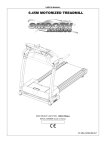
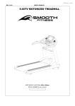
USER’S MANUAL
SMOOTH AGILE TRAINER
USER WEIGHT LIMITATION: 350lbs(160kgs).
SERIAL NUMBER (found on frame):
ST-MNL-WT100-SMUS-06
2
SMOOTH AGILE TRAINER
PREASSEMBLY
For future service or related questions:
Please staple your receipt and/or write in the name and phone number of the retail store where you purchased your Smooth
Fitness AGILE Dynamic Motion Trainer.
Name: ______________________________ Phone Number: ___________________ Receipt: ______________________
Open the boxes:
You are now ready to open the boxes of your new equipment. Make sure to inventory all of the parts that are included in the boxes.
Check the Parts List for a full count of the number of parts included for this product to be assembled properly. If you are missing
any parts or have any assembly questions call your local dealer or contact us directly at 888-800-1167.
Gather your tools:
Before starting the assembly of your unit, make sure that you have gathered all the necessary tools you may require to assemble
the unit properly. Having all of the necessary equipment at hand will save time and make the assembly quick and hassle-free.
Clear your work area:
Make sure that you have cleared away a large enough space to properly assemble the unit. Make sure the space is free from
anything that may cause injury during assembly. After the unit is fully assembled, make sure there is a comfortable amount of free
area around the unit for unobstructed operation.
Invite a friend:
Some of the assembly steps may require heavy lifting. It is recommended that you obtain the assistance of another person when
assembling this product.
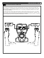
User Weight Limitation:
Please note that there is a weight limitation for this product. If you weigh more than 350lbs. it is not recommended that you use this
product. Serious injury may occur if the user’s weight exceeds the limit shown here. This product is not intended to support users
whose weight exceeds this limit.
www.smoothfitness.com
3
POWER REQUIREMENTS
Power Requirements:
IMPROPER CONNECTION OF THE EQUIPMENT GROUNDING CONNECTOR CAN RESULT IN THE RISK OF AN ELECTRIC
SHOCK. CHECK WITH A QUALIFIED ELECTRICIAN OR SERVICE MAN IF YOU ARE IN DOUBT AS TO WHETHER THE
PRODUCT IS PROPERLY GROUNDED. DO NOT MODIFY THE PLUG PROVIDED WITH THE PRODUCT, IF IT WILL NOT FIT
THE OUTLET; HAVE A PROPER OUTLET INSTALLED BY A QUALIFIED ELECTRICIAN.
This AGILE Trainer can be seriously damaged by sudden voltage changes in your home’s electrical power. Voltage spikes, surges
and noise interference can result from weather conditions or from other appliances being turned on or off. To reduce the possibility
of AGILE Trainer damage, always use a surge protector (not included) with your AGILE Trainer.
Surge protectors can be purchased at most hardware stores. The manufacturer recommends a single outlet surge protector with a
UL 1449 rating as a Transient Voltage Surge Suppressor (TVSS) with a UL suppressed voltage rating of 400V or less and an
electrical rating 110VAC, 15 amps.
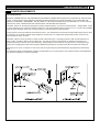
This AGILE Trainer must be grounded to reduce the risk of electrical shock. Grounding provides a path of least resistance for
electric current, should the AGILE Trainer malfunction. This AGILE Trainer is equipped with an electrical cord that has an
equipment-grounding conductor and a grounding plug. Always plug the power cord into a surge protector, and plug the surge
protector into an appropriate outlet that is properly installed and grounded in accordance with all local codes and ordinances.
This product is for use on a nominal 110-volt circuit, and has a grounding plug that looks like the plug illustrated in the drawing
below.
GFCI outlets and GFCI Circuit Breakers are NOT recommended for use on this product. GFCI outlets and GFCI Circuit Breakers
may cause this equipment to function improperly.
4
SMOOTH AGILE TRAINER
SUPPLIED COMPONENTS
This list identifies the major components you will use to assemble this product.
BOX - A
Main Frame
Assembly
Main
Frame
Assembly
Handlebar Assembly
Handlebar
Assembly
BOX - B
Fixed Handlebar
Console Support
Tube
Base Frame
Upright-Left
Undercarriage Cover
Upright-Right
www.smoothfitness.com
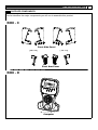
SUPPLIED COMPONENTS
This list identifies the major components you will use to assemble this product.
BOX - C
Front Side Panel
[ 712 / 711 ]
[ 709 / 710 ]
Pivot Arm Cover
BOX - D
Computer
Computer
5
6
SMOOTH AGILE TRAINER
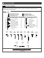
SUPPLIED HARDWARE
This list identifies the hardware you will use to assemble the product. To help distinguish
between the various types of screws and bolts, use the scale below to measure them and
compare them to the sizes listed.
BOX - E
701 Upright Side Cover-Left
702 Upright Side Cover-Right
703 Console Back Cover
717 Pivot Cap 2PCS
718 Pivot Side Cap 2PCS
721 Pedal Arm Front Pivot 4PCS
501
12 x 62 - M10 x 20mm Bolt
2P CS
512
4 x 12 mm Screw
10PCS
502
20 x 78 - M14 x 35mm Bo lt
2PC S
513
4 x 19mm Screw
6P CS
503
M5 x 8mm Screw
2P CS
514
12 x 18 x 24.5mm Sleeve
2P CS
504
M8 x 20mm Allen Hea d Bolt
4PC S
515
12 x 22 x 2 Was her
2PC S
505
M8 x 40mm Allen Hea d Bolt
2PC S
516
M5 x 6mm Bolt
2P CS
506
M8 x 65mm Allen Hea d Bolt
2PCS
517
M8 Nylon Nut
4PC S
507
M10 x 20mm Allen Head Bolt
4PC S
518
8x20x1 .5mm Cup Washer
4PC S
508
M10 x 62 mm Allen Head Bolt
1P CS
519
M8x105x20 m
m Carriage Bolts
4PC S
509
M6 x 40mm Sc rew
2PCS
520
M6x12mm Allen Head Bolt
8P C S
510
12 x 20 x 2 Spring Washe r
2PCS
521
6x13x1mm Washer
8P C S
511
M10 Nylon Nut
1P CS
A
Screwdriver-L
(1 piece)
B
2.5mm
Allen key
C
5mm
Allenkey
D
6mm
Allen key
E
8mm
Allenkey
(1 piece)
(1 piece)
(1 piece)
(1 piece)
F
Wrench
H
5mm
AllenWrench
Water Bottle
(1 piece)
(1 piece)
(1 piece)
(1 piece)
K
L
PowerCord
Chest Belt
4mm
Allen key
(1 piece)
(1 piece)
(1 piece)
J
I
G
Slotted
Screwdriver
MILLIMETERS
www.smoothfitness.com
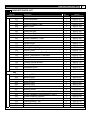
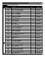
COMPLETE PARTS LIST
Item No.
Description
Qty.
Part No.
100
101
102
103
104
105
106
107
108
109
110
111
112
113
114
115
116
117
118
119
120
121
122
Fixed Handlebar
Crossbar
Console Support Tube
Base Frame
Main Frame
Pedal Arm-Left
Pedal Arm-Right
Action Handlebar - Left
Action Handlebar - Right
Upright-Left
Upright-Right
Moving Linkage-Left
Moving Linkage-Right
Incline Frame
Incline Transmission Tube-Front
Incline Transmission Tube-Back
Clamp Bracket
Flywheel
Tension Wheel Bracket
Pedal Swing Arm
Hold Base-Front
Hold Base-Back
1
1
1
1
1
1
1
1
1
1
1
1
1
1
1
1
2
1
1
2
1
1
AGILE-101
AGILE-102
AGILE-103
AGILE-104
AGILE-105
AGILE-106
AGILE-107
AGILE-108
AGILE-109
AGILE-110
AGILE-111
AGILE-112
AGILE-113
AGILE-114
AGILE-115
AGILE-116
AGILE-117
AGILE-118
AGILE-119
AGILE-120
AGILE-121
AGILE-122
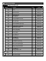
200
201
202
203
204
205
206
207
208
209
210
211
212
213
214
Bearing 6004
Bearing 6005
Bearing 6300
Bearing 6804
Bearing 2203
Bearing 6205
Bearing 608zz
Action Handlebar Shaft Bushing 2"x38-20
Action Handlebar Shaft Bushing 2"x38-9
Elector-magnetic System
Oil-Impregnated Bearing
Clamp Bushing- Top
Clamp Bushing- Bottom
Belt
4
2
6
4
2
4
8
2
2
1
2
2
2
1
AGILE-201
AGILE-202
AGILE-203
AGILE-204
AGILE-205
AGILE-206
AGILE-207
AGILE-208
AGILE-209
AGILE-210
AGILE-211
AGILE-212
AGILE-213
AGILE-214
7
8
SMOOTH AGILE TRAINER
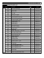
COMPLETE PARTS LIST
Item No.
215
216
217
218
219
220
221
222
224
225
226
227
228
229
230
231
232
233
234
235
238
239
240
241
242
243
244
245
246
247
248
249
250
252
253
300
302
303
Description
Qty.
Part No.
Aluminum Disk
Crank
Crank 25x186.7
Crank Disk Axle
Wheel
Pedal Buffer Set
Level Adjuster
Crank Disk
Fixed Handlebar End Cap
Hand Pulse Sensor Cover
Oval Tube Cap
Hand Pulse Sensor Back Cover
Fixed Handlebar Foam Grip
Electro-magnetic System Bracket
Flywheel Axle Fixing Plate
Speed Sensor Base
Pedal Support Base
Pedal Fixing Base
Crank Disk Oval Cap
Switch Fascia
Bearing 2201
5/16" Cable Tie
1/8" Cable Tie
3/8" Cable Tie
Wheel Bushing
Bearing 6000
Self-adhesive Wire Clip
Incline Frame Bushing #1
Incline Frame Bushing #2
Incline Frame Bushing #3
Incline Frame Bushing #4
3/16" Cable Tie
1/4" Cable Tie
Bearing Support Tube
Rear Shroud Holder
1
1
1
1
2
2
2
1
2
2
2
2
2
1
1
1
2
2
1
1
2
1
1
4
4
3
1
2
2
2
23
1
9
1
1
AGILE-215
AGILE-216
AGILE-217
AGILE-218
AGILE-219
AGILE-220
AGILE-221
AGILE-222
AGILE-224
AGILE-225
AGILE-226
AGILE-227
AGILE-228
AGILE-229
AGILE-230
AGILE-231
AGILE-232
AGILE-233
AGILE-234
AGILE-235
AGILE-238
AGILE-239
AGILE-240
AGILE-241
AGILE-242
AGILE-243
AGILE-244
AGILE-245
AGILE-246
AGILE-247
AGILE-248
AGILE-249
AGILE-250
AGILE-252
AGILE-253
Rear Shroud-Left
Rear Shroud-Right
1
1
AGILE-302
AGILE-303
www.smoothfitness.com
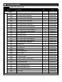
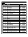
COMPLETE PARTS LIST
Item No.
Description
Qty.
Part No.
304
Rear Side Panel-Left
1
AGILE-304
305
Rear Side Panel-Right
1
AGILE-305
306
Switch Plate
1
AGILE-306
307
Pedal
2
AGILE-307
308
Toe Cap
2
AGILE-308
309
Pedal Soft Cushion
2
AGILE-309
310
Pedal Bushing Cover-Left
2
AGILE-310
311
Pedal Bushing Cover-Right
2
AGILE-311
312
Console Housing - Upper
1
AGILE-312
313
Console Housing – Bottom
1
AGILE-313
314
Console Plastic Cover
1
AGILE-314
315
Rubber Strip-4
4
AGILE-315
316
Rubber Strip-3
4
AGILE-316
317
Rubber Strip-2
4
AGILE-317
318
Rear Shroud Plug-1
2
AGILE-318
319
Rear Shroud Plug-2
2
AGILE-319
320
Rubber Strip-1
4
AGILE-320
321
Cable Plug
2
AGILE-321
322
Incline Transmission Tube Holder
1
AGILE-322
323
Moving Linkage Bushing
4
AGILE-323
324
Control Board Cover
1
AGILE-324
325
Pedal Swing Arm Cap
2
AGILE-325
326
Taper Fixing Insert
35
AGILE-326
327
Support Lump
1
AGILE-327
328
Oblong Cushion
2
AGILE-328
329
Circular Cushion
2
AGILE-329
330
Rubber Cushion – Front
2
AGILE-330
331
Rubber Cushion – Rear
2
AGILE-331
332
Fixing Insert
22
AGILE-332
333
Fixing Insert-Metal Inside
7
AGILE-333
336
Action Handlebar Front Cover
4
AGILE-336
337
Action Handlebar Cover
2
AGILE-337
338
Elbow-Left
2
AGILE-338
339
Elbow-Right
2
AGILE-339
340
Button
1
AGILE-340
341
Taper Fixing Insert-Metal Inside
3
AGILE-341
9
10
SMOOTH AGILE TRAINER
COMPLETE PARTS LIST
Item No.
Description
Qty.
Part No.
400
402
25 x 10 x 55 - M10 x 15mm Bolt
2
AGILE-402
403
M5 x 8mm Allen Head Bolt
7
AGILE-403
404
M6 x 12mm Allen Head Bolt
11
AGILE-404
405
M8 x 15mm Allen Head Bolt
23
AGILE-405
406
M8 x 25mm Allen Head Bolt
2
AGILE-406
407
M10 x 20mm Allen Head Cap Bolt
4
AGILE-407
408
M10 x 40mm Allen Head Bolt
1
AGILE-408
409
M4 X 40mm Allen Head Cap Bolt
1
AGILE-409
410
M8 x 50mm Allen Head Cap Bolt
2
AGILE-410
411
M10 x 40mm Allen Head Cap Bolt
2
AGILE-411
412
M12 x 70mm Allen Head Cap Bolt
2
AGILE-412
414
M8 x 20mm Bolt
6
AGILE-414
415
M3 x 8mm Screw
2
AGILE-415
416
M8 x 65mm Allen Head Cap Bolt
2
AGILE-416
417
M6 x 12mm Allen Head Cap Bolt
2
AGILE-417
418
M8 x 16mm Allen Head Cap Bolt
4
AGILE-418
419
M8 x 90mm Allen Head Bolt
4
AGILE-419
421
M8 Nylon Nut
8
AGILE-421
422
M10 Nylon Nut
3
AGILE-422
423
M14 Nylon Nut
3
AGILE-423
424
M8 Blind Nut
2
AGILE-424
425
M6 x 15mm Screw
2
AGILE-425
426
3/4" x 16 Nut
2
AGILE-426
427
Flywheel Axle
1
AGILE-427
428
10 x 36mm Shaft
2
AGILE-428
429
12 x 210 - M14 x 70mm Shaft
1
AGILE-429
430
Bushing 12 x 60
4
AGILE-430
431
M4 x 15mm Screw
2
AGILE-431
432
4 x 12mm Round Head Screw
8
AGILE-432
433
Action Handlebar Shaft
1
AGILE-433
434
Pedal Arm Support Axle
2
AGILE-434
435
Crank Axle Bushing
2
AGILE-435
436
M10 C Clip
6
AGILE-436
437
M12 C Clip
2
AGILE-437
www.smoothfitness.com
11
COMPLETE PARTS LIST
Item No.
438
439
440
441
442
443
444
445
446
447
448
449
450
451
452
453
454
456
457
458
459
460
461
462
463
464
465
466
467
468
500
501
502
503
504
505
506
507
508
509
Description
Qty.
Part No.
M42 C Clip
10 x 18 x T1.0 Fiber Washer
15 x 8 x T2.0 Spring Washer
10 x 16 x T2.0 Spring Washer
20 x 6 x T2.0 Washer
32 x 6 x T2.0 Washer
35 x 14 x T2.0 Washer
10 x 18 x T5.1 Washer
M3 x 16mm Screw
M3 x 10mm Screw
4 x 12mm Screw
M2 x 6mm Screw
4 x 12mm Coarse Thread Screw
M32 C Clip
M4 x 45mm Screw
M4 x 8mm Screw
7 x 12 - M5 x 5mm Pin Nut
10 x 23 x T2.0 Washer
6 x 10 x 1 Spring Washer
28.6 x 35.5 Bushing
12 x 20 x 0.5 Washer
12 x 20 x 2 PU Washer
4 x 12mm Self Tapping Screw
M8 x 16mm Bolt
4 x 12mm Screw-cone point
4 x 30mm Screw
M4 Nut
M5 Nut
5 x 0.6mm Lock Washer
M5 x 15mm Screw
2
2
11
7
3
1
2
4
2
18
38
8
23
2
2
4
4
4
2
2
2
2
6
8
4
2
2
2
1
1
AGILE-438
AGILE-439
AGILE-440
AGILE-441
AGILE-442
AGILE-443
AGILE-444
AGILE-445
AGILE-446
AGILE-447
AGILE-448
AGILE-449
AGILE-450
AGILE-451
AGILE-452
AGILE-453
AGILE-454
AGILE-456
AGILE-457
AGILE-458
AGILE-459
AGILE-460
AGILE-461
AGILE-462
AGILE-463
AGILE-464
AGILE-465
AGILE-466
AGILE-467
AGILE-468
12 x 62 - M10 x 20mm Bolt
20 x 78 - M14 x 35mm Bolt
M5 x 8mm Screw
M8 x 20mm Allen Head Bolt
M8 x 40mm Allen Head Bolt
M8 x 65mm Allen Head Bolt
M10 x 20mm Allen Head Bolt
M10 x 62mm Allen Head Bolt
M6 x 40mm Screw
2
2
2
4
2
2
4
1
2
AGILE-501
AGILE-502
AGILE-503
AGILE-504
AGILE-505
AGILE-506
AGILE-507
AGILE-508
AGILE-509
12
SMOOTH AGILE TRAINER
COMPLETE PARTS LIST
Item No.
510
511
512
513
514
515
516
517
518
519
520
521
600
601
602
603
604
605
606
607
608
609
610
611
612
613
614
615
616
617
618
619
620
621
622
623
624
626
Description
Qty.
Part No.
12 x 20 x 2 Spring Washer
M10 Nylon Nut
4 x 12mm Screw
4 x 19mm Screw
12 x 18 x 24.5mm Sleeve
12 x 22 x 2 Washer
M5 x 6mm Bolt
M8 Nylon Nut
8 x 20 x 1.5mm Cup Washer
M8 x 105 x 20mm Carriage Bolt
M6 x 12mm Allen Head Bolt
6 x 13 x 1mm Washer
2
1
10
6
2
2
2
4
4
4
8
8
AGILE-510
AGILE-511
AGILE-512
AGILE-513
AGILE-514
AGILE-515
AGILE-516
AGILE-517
AGILE-518
AGILE-519
AGILE-520
AGILE-521
Speed Sensor
Magnetic Sensor
Power Switch
Power Breaker
Power Insert Set
Receiver
Transformer
Computer PC Board
Elevation Motor
Control Board
Button Sticker
Overlay
Elector-magnetic Wire
Power Connect Wire
8Pin Power Wire-Top 200mm
8Pin Power Wire-Upper 1000mm
8Pin Power Wire-Middle 900mm
8Pin Power Wire-Lower 800mm
8Pin Power Wire-Bottom 2700mm
3C Power Wire 1000mm
Hand Pulse Sensor Wire-Top 350mm
Hand Pulse Sensor Wire-Upper 620mm
Hand Pulse Sensor Wire-Lower 650mm
Receiver Wire 350mm
Control Board Connect Wire 250mm
1
1
1
1
1
1
1
1
1
1
1
1
1
3
1
1
1
1
1
1
2
2
2
1
1
AGILE-601
AGILE-602
AGILE-603
AGILE-604
AGILE-605
AGILE-606
AGILE-607
AGILE-608
AGILE-609
AGILE-610
AGILE-611
AGILE-612
AGILE-613
AGILE-614
AGILE-615
AGILE-616
AGILE-617
AGILE-618
AGILE-619
AGILE-620
AGILE-621
AGILE-622
AGILE-623
AGILE-624
AGILE-626
www.smoothfitness.com
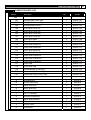
COMPLETE PARTS LIST
Item No.
Description
Qty.
Part No.
700
701
Upright Side Cover-Left
1
AGILE-701
702
Upright Side Cover-Right
1
AGILE-702
703
Console Back Cover
1
AGILE-703
704
Pivot Arm Cover-LL
1
AGILE-704
705
Pivot Arm Cover-LR
1
AGILE-705
706
Pivot Arm Cover-RR
1
AGILE-706
707
Pivot Arm Cover-RL
1
AGILE-707
708
Pivot Arm Insert
2
AGILE-708
709
Front Side Panel-LL
1
AGILE-709
710
Front Side Panel-LR
1
AGILE-710
711
Front Side Panel-RR
1
AGILE-711
712
Front Side Panel-RL
1
AGILE-712
713
Front Side Frame-LL
1
AGILE-713
714
Front Side Frame-LR
1
AGILE-714
715
Front Side Frame-RR
1
AGILE-715
716
Front Side Frame-RL
1
AGILE-716
717
Pivot Cap
2
AGILE-717
718
Pivot Side Cap
2
AGILE-718
719
Undercarriage Cover-Left
1
AGILE-719
720
Undercarriage Cover-Right
1
AGILE-720
721
Pedal Arm Front Pivot Cover
4
AGILE-721
A
Screwdriver-L
1
AGILE-A
B
2.5mm Allen Key
1
AGILE-B
C
5mm Allen Key
1
AGILE-C
D
6mm Allen Key
1
AGILE-D
E
8mm Allen Key
1
AGILE-E
F
14 x 17 Wrench
1
AGILE-F
G
Slotted Screwdriver
1
AGILE-G
H
5mm Allen Wrench
1
AGILE-H
I
Water Bottle
1
AGILE-I
J
Power Cord
1
AGILE-J
K
Chest Belt
1
AGILE-K
13
14
SMOOTH AGILE TRAINER
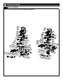
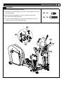
PARTS DIAGRAM
MOST OF THE PARTS SHOWN HERE HAVE BEEN PRE-ASSEMBLED.
703
224
326
101
228
509
424
450
608
321
314
208
449
447
504
321
102
340
612
312
611
450
313
433
208
www.smoothfitness.com
15
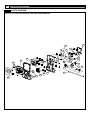
PARTS DIAGRAM
MOST OF THE PARTS SHOWN HERE HAVE BEEN PRE-ASSEMBLED.
505
447 227
326
225
103
338
225
326
227 447
447
336
432
701 506
336 432
339
209
338
416
339 447
336
432 336
201
504
506 702
448
448
110
721 501
201
448
337
108
510 451
448
514
112
109
337
209
504
416
111
113
517
519
518
517
326
514
238 451
515 510
515 238
519
518
320
332
513
517
518
501 721
513
315
332
326
320
316
332
709
519
519
518
519
317
315
512
710 513
326
447
332
713
513
316
332
714
513 712
317
326
711
447
332
716
715
512
513
16
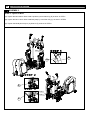
SMOOTH AGILE TRAINER
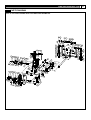
PARTS DIAGRAM
MOST OF THE PARTS SHOWN HERE HAVE BEEN PRE-ASSEMBLED.
308
308
309
309
404
406
404
406
307
450
307
450
331
330
331
232
414
310 326
421
405 330
414
421
207
421
220
430 207
448 310
437 233
421
220
448
207
419 311
448
419
430
204 502
721
323
417 457
442 438
205
232
405
459
326
323
106
233
204
459
721
107
502 460
323 437
460
405
405 311
448
205 438
442 457
417
www.smoothfitness.com
17
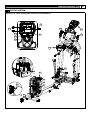
PARTS DIAGRAM
MOST OF THE PARTS SHOWN HERE HAVE BEEN PRE-ASSEMBLED.
423 444
717 503
206
718 503
717
458 206
120
206 458
206 444
423
407
441
516
456
117
421 429
407
423
456
325
212
325
248
245
508
412
229
442 439
427 405
210
440
215
246
412
115
418
440
1 16-1
1 16-2
440
116 -3
230
418
116 -1
122
327
464
425
422
226
221
221
426
404 405
216 434
440 411
414
434
218
404
253 202
443
435
441
217
426 465
602 431
441
411
226
609 408
246
247
213
440
214
248
114
211
322
403
405 440
234 441
435 202
222
245
213
116
404 436
243 405
212
247
410
118 243
439 436
441
117
511
18
SMOOTH AGILE TRAINER
PARTS DIAGRAM
MOST OF THE PARTS SHOWN HERE HAVE BEEN PRE-ASSEMBLED.
704
450
708
705
436 428
326
512
242
436
219
450
250
512
436
448
428 242
707
708
450
326
448
326
448 240 512 719
403
119 409 121
329
461
463
706
328
219
436
512
104
329
402 445 203 445 422
468
507
326
318
461
319
448
448
463
607
448
461
241
239
601
333
463
332
241
249
454
448
610
452
453
318
235
403
306
319
415
302
324
448
603
304
720
448 467
250
105
448
512
466
446 231
333
252
461
328
244
604
333
605
332
403
448
303
305
326
450
512
www.smoothfitness.com
19
PARTS DIAGRAM
MOST OF THE PARTS SHOWN HERE HAVE BEEN PRE-ASSEMBLED.
615
623
621
624
615
626
623
616
606
340
623
617
622
620 607 609
619
617
601
613
618
613
620
619
620
613
614
614
620
619
20
SMOOTH AGILE TRAINER
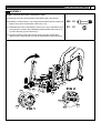
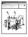
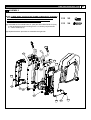
ASSEMBLY
STEP 1: Connect the Main Frame to Base Frame
(A) Rotate Incline Frame (114) up to vertical position.
(B) Place cardboard block under Main Frame tube to provide clearance to
position Base Frame (104) for assembly.
507
X4
(C) Position Base Frame (104) under mounting bracket of the Main Frame
(105) and align the 4 hole bolt pattern.
(D) Remove cardboard block and lower Main Frame (105) onto Base Frame
(104). Mounting Brackets should seat fully onto Base Frame (104).
Secure using four M10 x 20mm Allen Head Bolts (507).
507
114
105
104
A
c
B
507
618
619
104
105
Mounting Brackets
www.smoothfitness.com
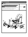
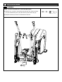
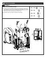
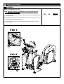
ASSEMBLY
STEP 2: Connect the Incline Transmission Tube
(A) Remove the Incline Transmission Tube Holder (322), and discard.
(B) Rotate the Incline Frame (114) to align the bolt holes with the mating bolt
holes in the Incline Transmission Tube-Front (115).
508 X1
(C) Assemble the Incline Transmission Tube-Front (115) to the Base Frame
(104) with M10 x 62mm Allen Head Bolt (508) and M10 Nylon Nut (511)
by 6mm Allen Key (D) and Wrench (F).
511 X1
(D) Connect the 8Pin Power Wire-Lower (618) to the 8Pin Power Wire
-Bottom (619), and fixed the wire into the Self-adhesive Wire Clip (244).
114
115
D
508
F
511
105
115
FIG 2
104
332
619
114
FIG 1
618
244
21
22
SMOOTH AGILE TRAINER
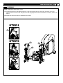
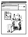
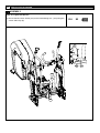
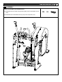
ASSEMBLY
STEP 3: Assemble the Undercarriage Covers
NOTE:THE UNDERCARRIAGE COVER-LEFT(719) FITS OVER THE 8PIN
POWER WIRE-LOWER (618). BE CAREFUL NOT TO DISCONNECT
THE WIRE WHEN ASSEMBLING THE UNDERCARRIAGE COVER
-LEFT (719).
512
X4
(A) Lift the Pedal Arm and assemble the Undercarriage Cover-Left (719) to the
Base Frame (104), and secure using four 4 x 12mm Screws (512).
(B) Repeat the above procedure to assemble the right side.
107
512
106
105
512
720
104
618
719
www.smoothfitness.com
23
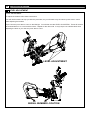
ASSEMBLY
STEP 4: Attach the Pivot Arm Covers
(A) Thread the free end of the Pedal Swing Arm (120) through the hole in the Pivot Arm Cover-RL (707) and
maneuver the Pivot Arm Cover-RL(120) to it’s final upright position. See the illustrations in STEP1, STEP2, and
STEP3.
(B) Repeat the above procedure to assemble the left side.
STEP1
120
707
STEP2
707
707
120
120
STEP3
707
120
705
24
SMOOTH AGILE TRAINER
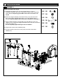
ASSEMBLY
STEP 5: Assemble the Upright
(A) Assemble the Upright-Left (110) and Upright-Right (111) to the
Handlebar assembly and secure using two M8 x 56mm Allen Head Bolts
(506). Do not completely tighten M8 x 56mm Allen Head Bolts until
step D.
506 X2
(B) Place the Upright Assembly to the Base Frame (104) and secure with
M6 x 12mm Allen Head Bolt (520) and 6 x 13 x 1mm Washer (521).
Do not completely tighten M6 x 12mm Allen Head Bolts until STEP 11.
518 X4
517 X4
519 X4
(C) Align the M8x105x20mm Carriage Bolt (519) with M8x20x1.5mm Cup
Washer (517) to thread the Upright and Base Frame, and then use the M8
Nylon Nut to tight (517).
Do not completely tighten M8 Nylon Nut until STEP 11.
520 X8
521 X8
(D) Tighten M8 x 56mm Allen Head Bolt (506).
(E) Connect the 8Pin Power Wire-Lower (618) to the 8Pin Power WireMiddle (617).
506 111
109
102
108
110 506
110
519
520
521
517
518
111
518
517
518
520
521
521
517
519
521
617
520
520
521
519
521
520
618
520
521
521
520
518
517
519
www.smoothfitness.com
ASSEMBLY
STEP 6: Assemble the Pivot Arm Covers
(A) Assemble the Pivot Arm Cover-RR (706) and the Pivot Arm Cover (707)
using the press-fit pins and secure to the frame using four 4 x 12mm
Screws (512).
512
X4
(B) Repeat the above procedure to assemble the left side.
707
705
706
512
704
512
512
25
26
SMOOTH AGILE TRAINER
ASSEMBLY
STEP 7: Connect the Pedal Arm to the Pedal Swing Arm
(A) Slide the 20 x 78-M14 X 35mm Bolt (502) through the Pedal Arm-Right
(107) and Pedal Swing Arm (120) the secure by 8mm Allen Key (E).
(B) Repeat the above procedure to assemble the left side.
502
E
502
X2
www.smoothfitness.com
ASSEMBLY
STEP 8: Assemble the Pivot Cap
503
X2
717
X2
718
X2
NOTE: ALIGN THE 3 SNAP FIT TABS ON THE PEDAL SIDE CAPS (718)
WITH THE 3 SNAP FIT ON THE PEDAL CAPS (717).
(A) Assemble the Pivot Cap (717) to the Pedal Swing Arm (120) and secure
using the M5 x 8mm Screw (503) by Slotted Screwdriver(G).
(B) Press the Pedal Side Cap (718) to the Pedal Cap (717).
717
503
717 503 718 503 717
G
27
28
SMOOTH AGILE TRAINER
ASSEMBLY
STEP 9: Assemble the Console Support Tube
NOTE: INSERT BOTH ENDS OF THE CONSOLE SUPPORT TUBE AT THE
SAME TIME.
504
(A) Connect the 8Pin Power Wire-Upper (616) to the 8Pin Power Wire-Middle
(617).
X2
(B) Assemble the Consol Support Tube (103) to the Upright and secure using
the M8 x 20mm Allen Head Bolt (504).
FIG 1
616
103
616
617
110
110
111
504
www.smoothfitness.com
ASSEMBLY
STEP 10: Assemble the Fixed Handlebar
(A) Assemble the Fixed Handlebar (101) to the Console Support Tube (103)
and Crossbar (102).
(B) Secure the Fixed Handlebar (101) to the Crossbar (102) with two
M8 x 20mm Allen Head Bolts (504).
504 X2
505 X2
(C) Secure the Fixed Handlebar (101) to the Console Support Tube (103)
with two M8 x 40mm Allen Head Bolts (505).
101
103
101
505
103
102
504
102
29
30
SMOOTH AGILE TRAINER
ASSEMBLY
STEP 11: Tighten all Bolts
(A) Tighten the M8 x 65mm Allen Head Cap Bolt by 6mm Allen Key (D) as show in STEP1.
(B) Tighten the M6 x 12mm Allen Head Bolt (520) by 4mm Allen Key (L) as show in STEP2.
(C) Tighten the M8 Nylon Nut (517) by Wrench (F) as show in STEP3.
STEP 1
STEP1
416
STEP 2
L
STEP 3
STEP 2
STEP 3
F
D
www.smoothfitness.com
ASSEMBLY
STEP 12: Assemble Upright Side Covers
(A) Press the Upright Side Cover-Left (701) and Upright Side Cover-Right
into the Upright sides.
701
X1
702
X1
701
110
702
111
31
32
SMOOTH AGILE TRAINER
ASSEMBLY
STEP 13: Connect the Moving Linkage
(A) Connect the Action Handlebar-Right (109) to the Moving Linkage-Right
(113) and secure using the 12 x 62-M10 x 20mm Bolt (501), 12 x 2 x 2mm
Spring Washer (510), 12 x 22 x 2mm Washer (515), and 12 x 18 x 24.5
Sleeve (514) by 6mm Allen Key (D), as show in FIG1.
(B). Repeat the above procedure to assemble the left side.
501 X2
510 X2
514 X2
515 X2
FIG 1
D
515
109
501 514
113
D
515 514
501 510
113
www.smoothfitness.com
ASSEMBLY
STEP 14: Assemble the Pedal Arm Front Pivot Covers
(A) Press the Pedal Arm Front Pivot Cover (721) into the ends of the Action
Handlebar-Right (109) and Pedal Arm-Right (107).
(B) Repeat the above procedure on the left side.
108
109 107
721
721
721
X4
33
34
SMOOTH AGILE TRAINER
ASSEMBLY
STEP 15: Tighten Set Screws
(A) Secure the M5 x 6mm Screw (516) to the Pedal Swing Arm (120) using the
2.5mm Allen Key (B).
516
X2
B
516
106
120
B
516
120
www.smoothfitness.com
ASSEMBLY
STEP 16: Assemble the Front Side Panels
NOTE: THERE ARE 2 HOLES IN THE FRAME COMPONENTS THROUGH
WHICH THE INSIDE AND OUTSIDE PLASTIC PANELS CONNECT
TO EACHOTHER. USE THESE HOLES AS REFERENCES TO
CORRECTLY POSITION THE PLASTIC PANELS.
(A) Assemble the Front Side Panel-LL (709) and Front Side Panel-LR (710)
to the left Upright and secure using one 4 x 12 Screw (512) and three
4 x 19mm Screws (513).
512
X2
513
X6
(B) Repeat the above procedure to assemble the right side.
111
110
710
513
513
512
711
712
513
709
512
513
35
36
SMOOTH AGILE TRAINER
ASSEMBLY
STEP 17: Assemble the Console
NOTE: BE SURE TO PUSH THE WIRES INTO THE CONSOLE BEFORE
YOU SECURE TO THE FRAME.
(A) Connect the 8Pin Power Wire-Top (615) to the 8Pin Power Wire-Upper (616)
as show in FIG1.
(B) Assemble the Computer (312) to the Console Support Tube (103) and secure
using two M6 x 40mm Screws (509).
(C) Connect the Hand Pulse Sensor Wire-Upper (622) to Computer (312) as
show in FIG2.
FIG 1
615
616
312
103
FIG 2
312
622
509
509
X2
www.smoothfitness.com
ASSEMBLY
STEP 18: Assemble Console Back Cover
(A) Assemble the four Taper Fixing Inserts (326) to the Console Back Cover
(703).
(B) Assemble the Console Back Cover (703) to the Computer (312).
312
703
326
X4
37
38
SMOOTH AGILE TRAINER
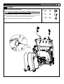
LEVEL ADJUSTMENT
LEVEL ADJUSTMENT:
To adjust the levelers follow these instructions:
You will need someone to help you with this procedure, as you will need to tip, the AGILE Dynamic Motion Trainer
while adjusting the levelers
Tip the AGILE Dynamic Motion Trainer to the left/right. You will then see the LEVEL ADJUSTERS. These will need to
be screwed either in or out to level the trainer. Repeat for the other side. It may help to use a bubble level when
adjusting the level on your AGILE Dynamic Motion Trainer.
LEVEL ADJUSTMENT
SERIAL NUMBER LOCATION
www.smoothfitness.com
39
LITE-TOUCH CONTROL OPERATION
LITE-TOUCH CONTROL:
The Intensity Level and Motion Level can be controlled using the Lite-Touch controls on the hand grips of the
action handlebars. As the illustration indicates, the right Lite-Touch Controller controls the Motion Level and the
left Lite-Touch Controller controls the Intensity Level. You can see the corresponding readouts on the console
follow this same orientation.
To use the Lite-Touch Controls, simply start a program or select START and begin your work out. To increase
either the Motion Level or the Intensity Level, move your thumb to the thumb groove with the “+” indicator. If you
hold your thumb in the thumb groove the level will continue to increase until you remove your thumb. To decrease
the level simply place your thumb in the groove marked with the “-“ indicator.
40
SMOOTH AGILE TRAINER
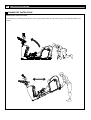
TRANSPORT INSTRUCTION
TRANSPORT INSTRUCTIONS:
To transport your AGILE Dynamic Motion Trainer simply lift the back end and roll it away to the desired location, as
shown.
www.smoothfitness.com
MUSCLE CHART
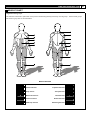
Targeted muscle groups:
The exercise routine that is performed on this product will develop primarily lower body muscle groups. These muscle groups
are shown in gray color on the chart below.
MUSCLE GROUPS
A
Shoulder muscles
B
Pectoral muscles
C
Bicep muscle
D
Abdominal muscles
E
Forearm muscles
F
Quadricep muscles
Calf muscles
G
Trapezius muscles
H
Tricep muscles
I
Back muscles
J
Gluteal muscles
K
Hamstring muscles
L
41
42
SMOOTH AGILE TRAINER
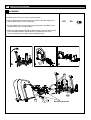
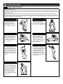
STRETCHING ROUTINE
Warm up and cool down:
A successful exercise program consists of a warm-up, aerobic exercise, and a cool-down. Do the entire program at least two and
preferably three times a week, resting for a day between workouts. After several months, you can increase your workouts to four
or five times per week.
Warming up is an important part of your workout, and should begin every session. It prepares your body for more strenuous
exercise by heating up and stretching out your muscles, increasing your circulation and pulse rate, and delivering more oxygen to
your muscles. At the end of your workout, repeat these exercises to reduce sore muscle problems. We suggest the warm-up and
cool-down exercises on the following pages:
Toe Touch:
Slowly bend forward from
your waist, letting your back
and shoulders relax as you
stretch toward your toes.
Reach down as far as you
can and hold for 15 counts.
Shoulder Lift:
Lift your right shoulder up
toward your ear for one
count. Then lift your left
shoulder up for one count as
you lower your right shoulder.
Inner Thigh Stretch:
Sit with the soles of your feet
together with your knees
pointing outward. Pull your
feet as close into your groin
as possible. Gently push
your knees towards the floor.
Hold for 15 counts.
Hamstring Stretch:
Sit with your right leg
extended. Rest the sole of
your left foot against your
right inner thigh. Stretch
toward your toe as far as
possible. Hold for 15 counts.
Relax and then repeat with
left leg extended.
Side Stretch:
Open your arms to the side
and continue lifting them until
they are over your head.
Reach your right arm as far
upward toward the ceiling as
you can for one count. Feel
the stretch up your right side.
Repeat this action with your
left arm.
Calf-Achilles Stretch:
Lean against a wall with your
left leg in front of the right
and your arms forward. Keep
your right leg straight and the
left foot on the floor; then
bend the left leg and lean
forward by moving your hips
toward the wall. Hold, and
then repeat on the other side
for 15 counts.
Head Roll:
Rotate your head to the right
for one count, feeling the
stretch up the left side of your
neck. Next, rotate your head
back for one count, stretching
your chin to the ceiling and
letting your mouth open.
Rotate your head to the left
for one count, and finally,
drop your head to your chest
for one count.
www.smoothfitness.com
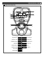
COMPUTER OPERATION
I
A
B
J
C
K
D
E
F
G
L
M
H
N
DTAT DISPLAY-1
A
I
DTAT DISPLAY-2
INTENSITY LEVEL
B
J
MOTION LEVEL
INTENSITY PROFILE
C
K
MOTION PROFILE
PROGRAMS
D
L
INTENSITY-UP
EXPRESS MOTION
E
M
START
INTENSITY-DOWN
F
N
MOTION-UP
STOP / ENTER
G
MOTION-DOWN
H
43
44
SMOOTH AGILE TRAINER
COMPUTER OPERATION
DISPLAY FUNCTIONS:
There are 6 display areas to show all the necessary information prior to and during the workout.
INTENSITY LEVEL DISPLAY:
Displays intensity level from 1 to 20.
8 x 16 DOT MATRIX INTENSITY LEVEL PROFILE DISPLAY:
Displays all operating instructions prior to the workout and displays intensity level profiles during the workout.
8 x 8 DOT MATRIX MOTION LEVEL PROFILE DISPLAY:
Displays motion level profiles during the workout.
MOTION LEVEL DISPLAY:
Displays motion levels from 1 to 12.
DATA DISPLAY 1:
Prior to using a preset program, data display 1 displays and allows user to set age, workout time and target heart rate.
During the workout, data display 1 displays TIME, RPM or PULSE depending on which display mode is selected. Scan mode
can also be selected to view all available data.
DATA DISPLAY 2:
Prior to using a preset program, data display 2 displays and allows user to set weight, distance target, calorie target or watt
target.
During the workout, data display 2 displays DISTANCE, CALORIES or WATTS depending on which display mode is selected.
Scan mode can also be selected to view all available data.
DISPLAY MODES:
Mode 1: Scan mode (scans through display modes 2-4)
Mode 2: TIME and DISTANCE
Mode 3: RPM and CALORIES
Mode 4: PULSE and WATTS
COMPUTER OPERATION:
POWER ON:
Plug in the POWER CORD and set the power switch to ON. All the LED windows will light up and begin scanning. The
INTENSITY LEVEL Dot Matrix displays and begins scrolling “SELECT-QUICK-START-OR-PROGRAM”. The other LED
windows will show the factory settings as follows:
INTENSITY LEVEL window display: “1”
MOTION LEVEL window display: “1”
DATA DISPLAY-1: displays (default AGE): ”35”, AGE LED light on.
DATA DISPLAY-2: displays (default WEIGHT): “150” lb, WEIGHT LED light on.
During the workout, press the STOP button twice to return to POWER ON status.
SLEEP MODE:
The computer will automatically enter SLEEP MODE if left idle for 3 minutes without any input in POWER ON status. When
the computer is in SLEEP MODE, press any button or pedal and the machine will return to POWER ON status. You can turn
SLEEP MODE off but the console will be drawing power indefinitely if it is plugged in to keep the LEDs lit. To turn SLEEP
MODE off, get the console to POWER ON status then press INTENSITY UP and DOWN buttons and hold for 5 seconds.
Data display 2 will show “1”. Press the START button and data display 2 will display the SLEEP MODE status. To toggle
between “On” and “Off”, select INTENSITY UP or DOWN then press STOP/ENTER to confirm and return to POWER ON
status.
PAUSE/STOP:
During the workout, press the STOP button or stop pedaling for 10 seconds to enter PAUSE status. The INTENSITY LEVEL
Dot Matrix display will show “PAUSE”. All the figures on the console will be frozen. Press the START button or start pedaling
to resume the program and all the displays will
www.smoothfitness.com
45
COMPUTER OPERATION
continue the performance until the program finishes. If you leave the pedal stopped for over 3 minutes or press the STOP
button twice, all the data will return to 0 and the computer will return to POWER ON status.
ENGLISH/METRIC CONVERSION:
The console display can show ENGLISH and METRIC information. The factory should have the proper setting on this for the
different markets. In case it needs to be converted between METRIC and ENGLISH readout, please follow the procedure
below:
1.Set the POWER SWITCH to ON. Press both the STOP and MOTION UP button at the same time and hold for 3 seconds.
The INTENSITY LEVEL Dot Matrix will display and scrolling “KM” or “ML”. KM is displayed for METRIC and ML for ENGLISH.
2. Press the INTENSITY UP/DOWN button to switch between Metric and English then pressing STOP/ENTER to save the
setting and return to Power On status.
SOUND on/off:
From the POWER ON status press and hold INTENSITY UP and DOWN buttons for 5 seconds to get to the
display control mode. The data display 2 will be displaying “1”. Press INTENSITY UP once so that “2” is
displaying then press the START button. To toggle between sound “on” or “off” use the INTENSITY UP or
DOWN button then press STOP/ENTER to confirm and return to POWER ON status.
PROGRAM OPERATING INSTRUCTION
QUICK START:
When the console is in POWER ON status, press the START button to activate the QUICK START program. The Intensity
Level Display shows “1” and the INTENSITY LEVEL Dot Matrix displays the intensity level profile. The Motion Level Display
shows “1” and the MOTION LEVEL Dot Matrix displays motion level profile. Press the INTENSITY UP/DOWN button to
change the intensity level. Press the MOTION UP/DOWN button to change the motion level. The TIME, CALORIES and
DISTANCE will count up from 0.
TARGET PROGRAM:
When the console is in POWER ON status, press the TARGET program button once to enter the TARGET TIME program set
up:
Press TARGET program button twice to enter the TARGET DISTANCE program set up,
Press TARGET PROGRAM button three times to enter the TARGET CALORIES program set up
Continue the rotation among these three target programs by pressing the TARGET program button.
Target Time:
Press the TARGET program button once to get to the TARGET TIME program, then press STOP/ENTER to enter the set up
procedure.
TIME display shows the factory default setting “30:00” . Press INTENSITY UP/DOWN button to adjust the target time and
press STOP/ENTER to confirm.
AGE display shows factory default setting “35” . Press INTENSITY UP/DOWN button to adjust the user age and press
STOP/ENTER to confirm.
WEIGHT display shows factory default setting “68(kgs)/150(Lb). Press INTENSITY UP/DOWN button to adjust the user
weight and press STOP/ENTER to confirm.
Press START button to start the target time program. Time counts down to 0, Distance and Calories count up. Press
INTENSITY UP/DOWN to adjust the resistance and press MOTION UP/DOWN to adjust the motion.
Target Distance:
Press the TARGET program button twice to get to the TARGET DISTANCE program then press STOP/ENTER to enter the
set up procedure.
DISTANCE display shows factory default setting “5.00”. Press INTENSITY UP/DOWN button to adjust the target distance and
press STOP/ENTER to confirm.
AGE display shows factory default setting “35”. Press INTENSITY UP/DOWN button to adjust the user age and press
STOP/ENTER to confirm.
46
SMOOTH AGILE TRAINER
COMPUTER OPERATION
WEIGHT display shows factory default setting “68(kgs)/150(Lb). Press INTENSITY UP/DOWN button to adjust the user
weight and press STOP/ENTER to confirm.
Press START button to start the target distance program. Distance counts down to 0, Time and Calories count up. Press
INTENSITY UP/DOWN to adjust the resistance and press MOTION UP/DOWN to adjust the motion.
Target Calories:
Press the TARGET program button three times to get to the TARGET CALORIES program, then press
STOP/ENTER to enter the set up procedure.
CALORIES display shows factory default setting “50”. Press INTENSITY UP/DOWN button to adjust the target
calories and press STOPE/ENTER to confirm.
AGE display shows factory default setting “35”. Press INTENSITY UP/DOWN button to adjust the user age and press
STOP/ENTER to confirm.
WEIGHT display shows factory default setting “68(kgs)/150(Lb). Press INTENSITY UP/DOWN button to adjust the user
weight and press STOP/ENTER to confirm.
Press START button to start the target distance program. Distance counts down to 0, Time and Calories count up. Press
INTENSITY UP/DOWN to adjust the resistance and press MOTION UP/DOWN to adjust the motion.
FAT BURNING PROGRAM
When the console is in POWER ON status, press the FAT BURNING program button then press STOP/ENTER
to continue the set up procedure.
TIME display shows factory default setting “30:00”. Press INTENSITY UP/DOWN button to adjust the target time and press
STOP/ENTER to confirm.
AGE display shows factory default setting “35”. Press INTENSITY UP/DOWN button to adjust the user age and press
STOP/ENTER to confirm.
WEIGHT display shows factory default setting “68(kgs)/150(Lb). Press INTENSITY UP/DOWN button to adjust the user
weight and press STOP/ENTER to confirm.
Press START button to start the FAT BURNING program. Time counts down to 0, Distance and Calories count up. Dot Matrix
display shows the pre-set INTENSITY and MOTION profile. Press INTENSITY UP/DOWN to adjust the resistance and press
MOTION UP/DOWN to adjust the motion.
INTERVAL PROGRAM
When the console is in POWER ON status, press the INTERVAL program button once to select the INTENSITY INTERVAL
program then press STOP/ENTER to enter the program set up procedure.
OR
Press INTERVAL program button twice to select the MOTION INTERVAL program then press STOP/ENTER to enter the
program set up procedure.
Continue the rotation between these two INTERVAL programs by pressing the INTERVAL program button.
Intensity Interval Program
When the console is in INTENSITY INTERVAL program set up, INTENSITY LEVEAL DISPLAY shows “L1”. This indicates the
intensity level for the intervals. Use the INTENSITY UP/DOWN buttons to change the intensity then press STOP/ENTER
button to enter to confirm.
TIME display shows factory default setting “32:00”. Press INTENSITY UP/DOWN button to adjust the target time and press
STOP/ENTER to confirm.
AGE display shows factory default setting “35”. Press INTENSITY UP/DOWN button to adjust the user age and press
STOP/ENTER to confirm.
WEIGHT display shows factory default setting “68(kgs)/150(Lb). Press INTENSITY UP/DOWN button to adjust the user
weight and press STOP/ENTER to confirm.
www.smoothfitness.com
47
COMPUTER OPERATION
Press START button to start the INTENSITY INTERVAL program. Time counts down to 0, Distance and Calories count up.
Dot Matrix display shows the pre-set INTENSITY and MOTION profile. Press INTENSITY UP/DOWN to adjust the resistance
and press MOTION UP/DOWN to adjust the motion.
Motion Interval Program
When the console is in MOTION INTERVAL program set up, MOTION LEVEAL DISPLAY shows “L1”. This indicates the
intensity level for the intervals. Use the INTENSITY UP/DOWN buttons to change the intensity then press STOP/ENTER
button to confirm.
TIME display shows factory default setting “32:00”. Press INTENSITY UP/DOWN button to adjust the target time and press
STOP/ENTER to confirm.
AGE display shows factory default setting “35”. Press INTENSITY UP/DOWN button to adjust the user age and press
STOP/ENTER to confirm.
WEIGHT display shows factory default setting “68(kgs)/150(Lb). Press INTENSITY UP/DOWN button to adjust the user
weight and press STOP/ENTER to confirm.
Press START button to start the MOTION INTERVAL program. Time counts down to 0, Distance and Calories count up. Dot
Matrix display shows the pre-set INTENSITY and MOTION profile. Press INTENSITY UP/DOWN to adjust the resistance and
press MOTION UP/DOWN to adjust the motion.
ENDURANCE PROGRAM
When the console is in POWER ON status, press the ENDURANCE program button then press STOP/ENTER to
continue to the set up procedure.
Workout Level set up
TIME display shows “L1”, Press INTENSITY UP/DOWN button to adjust the workout level and press STOP/ENTER to
confirm.
TIME display shows factory default setting “32:00”. Press INTENSITY UP/DOWN button to adjust the target time and press
STOP/ENTER to confirm.
AGE display shows factory default setting “35”. Press INTENSITY UP/DOWN button to adjust the user age and press
STOP/ENTER to confirm.
WEIGHT display shows factory default setting “68(kgs)/150(Lb). Press INTENSITY UP/DOWN button to adjust the user
weight and press STOP/ENTER to confirm.
Press START button to start the ENDURANCE program. Time counts down to 0, Distance and Calories count up. Dot Matrix
display shows the pre-set INTENSITY and MOTION profile. Press INTENSITY UP/DOWN to adjust the resistance and press
MOTION UP/DOWN to adjust the motion.
WATTS CONTROL PROGRAM
The function of Watts Control program is to allow the user to set a desired workout load (watts). The user’s
workout load is controlled automatically by increasing or decreasing the resistance as the user changes their
stride cadence (RPM). The intensity will be reduced when user increases RPM and the intensity will be increased
when the user decreases the RPM.
When the console is in POWER ON status, press the WATTS CONTROL program button then press
STOP/ENTER to continue the set up procedure.
WATTS display shows factory default setting “110”. Press INTENSITY UP/DOWN button to adjust the target Watts and press
STOP/ENTER to confirm.
TIME display shows factory default setting “32:00”. Press INTENSITY UP/DOWN button to adjust the target time and press
STOP/ENTER to confirm.
AGE display shows factory default setting “35”. Press INTENSITY UP/DOWN button to adjust the user age and press
STOP/ENTER to confirm.
48
SMOOTH AGILE TRAINER
COMPUTER OPERATION
WEIGHT display shows factory default setting “68(kgs)/150(Lb). Press INTENSITY UP/DOWN button to adjust the user
weight and press STOP/ENTER to confirm.
Press START button to start the WATTS program. Time counts down to 0, Distance and Calories count up. Dot Matrix display
shows the pre-set INTENSITY and MOTION profile. Press INTENSITY UP/DOWN to adjust the resistance and press MOTION
UP/DOWN to adjust the motion
TARGET HEART RATE CONTROL PROGRAM :
The TARGET HEART RATE CONTROL program is designed to keep the user training at their chosen heart rate level to
achieve the proper workout result. A heart rate monitoring device must be used for this program. The equipment provides a
standard contact handgrip on the moving handle bar to sense the user heart beat during the workout. The user must hold the
contact handgrips on the moving handle bar constantly in order to monitor the user heart rate during the workout. A wireless
chest belt transmitter is highly recommended for this program.
IMPORTANT: The console software will calculate the user’s SAFE MAXIMUM HEART RATE based on the formula:
220pbm-AGE. User’s are encouraged to consult with a doctor or personal
Training consultant to more accurately estimate their SAFE MAXIMUM HEART RATE in order to workout safely.
When the console is in POWER ON status, press the HEART RATE CONTROL program button. The 8x16 Dot Matrix displays
“HEART RATE CONTROL” Press STOP/ENTER to continue to the set up procedure.
TIME display shows factory default setting “30:00”. Press INTENSITY UP/DOWN button to adjust the target time and press
STOP/ENTER to confirm.
AGE display shows factory default setting “35”. Press INTENSITY UP/DOWN button to adjust the user age and press
STOP/ENTER to confirm.
PULSE display shows the calculated TARGET HEART RATE based on the user age setting from the above step. The
TARGET HEART RATE = 85% MAXIMUM SAFE HEART RATE. Press INTENSITY UP/DOWN button to adjust the target
heart rate then press the STOP/ENTER bottom to confirm.
WEIGHT display shows factory default setting “68(kgs)/150(Lb). Press INTENSITY UP/DOWN button to adjust the user
weight and press STOP/ENTER to confirm.
Press the START button to start the 3 minute WARM UP. The purpose of warm up program is to bring the user’s heart rate to
65% of the MAXIMUM SAFE HEART RATE. Time counts down from “3.00” to “0:00”. Intensity Level Profile displays “WARM
UP” 3 times. During the WARM UP, if the actual heart rate is less than 65% of the user’s MAXIMUM SAFE HEART RATE, the
intensity level will be increased by 1 level every 15 seconds. If the actual heart rate reaches 65% MAXIMUM SAFE HEART
RATE twice within the warm up, the HEART RATE CONTROL program will start.
If user’s actual hear rate fails to reach 65% of MAXIMUM SAFE HEART RATE during the warm up, the user will be placed
nd
rd
into a 2 or 3 (if necessary) 3 minute warm up program. If user’s actual heart rate fails to reach 65% of the MAXIMUM SAFE
HEART RATE after the 3rd 3 warm up program, the INTENSITY LEVEL PROFILE dot matrix will display “FAIL” then return to
POWER ON status in 10 seconds.
Once the user successfully enters the HEART RATE CONTROL program, the computer will actively adjust the motion level
and intensity level to keep the users at the TARGET HEART RATE. If the user is consistently below the TARGET HEART
RATE, the MOTION LEVEL will increase 1 level every 15 seconds until reach LEVEL 12 and then the INTENSITY LEVEL will
increase 1 level every 15 seconds. If the user reaches and exceeds the TARGET HEART RATE, the MOTION LEVEL will
decrease 1 level every 15 seconds until level 1 and then the INTENSITY LEVEL will decrease 1 level every 15 seconds. The
program will continue until the time runs out. If the user’s heart rate continues to exceed the TARGET HEART RATE for 3
minutes, or the time counts down to “0:00”, the heart rate control program will stop and start the 1 minute COOL DOWN
function. Time counts down from “1:00” and INTENSITY LEVEL AND MOTION LEVEL at level 1.
www.smoothfitness.com
49
WARRANTY
LIMITED HOME USE WARRANTY
Warranty Coverage: EVO Fitness and Smooth Fitness, Inc. ("Smooth Fitness") warrants to the original owner that each new product
to be free from defects in workmanship and material, under normal use and conditions.
Period of Coverage: The Warranty on this product runs from the date of original purchase using the following schedule:
Model Name
AGILE DMT
Frame
Lifetime
Parts & Electronics
5 years
Labor
1 year
Labor: Smooth Fitness will reimburse for labor costs for One (1) year. Smooth Fitness reserves the right to either:
Hire and reimburse an independent service technician who will come into the home for the repair,
OR
In the event that there is not an available certified Smooth Fitness service technician, Smooth will send the part directly to the
consumer and will pay $75 US per occurrence for the labor costs of such repair. If multiple repair attempts must be made for one
reported problem, Smooth will only reimburse once per occurrence.
Smooth Fitness reserves the right to inspect damaged parts for misuse. Your Original Receipt is proof of purchase and should be
kept with the product manual. You may be required to show proof of purchase prior to warranty service being initiated.
Remedy Provided by Smooth Fitness: Smooth Fitness will provide a replacement part free of charge if a defect is found during the
Warranty period. Smooth Fitness may at its discretion, choose to provide any of following parts or repair options. In the event that a
part is determined in need of replacement, upon receipt of the part by Smooth Fitness, Smooth Fitness may send out the part by UPS
ground or another such carrier directly to the customer’s home. The customer is responsible for the cost of sending the part to
Smooth Fitness.
For the 9.25X Model Only: This warranty covers all parts including frame, electronics and wear parts for a lifetime. If Smooth Fitness
in its sole discretion determines that the treadmill cannot or should not be repaired, it may decide to purchase the unit for the
residual value in accordance with the following: 25% of retail purchase price after 5 years, 15% after 10 years, 5% after 15 years.
Any redemption may be by repair or replacement of the affected parts and/or product at the sole discretion of Smooth Fitness, by
personnel approved by Smooth Fitness.
Parts repaired or replaced pursuant to this Warranty shall be warranted for the unexpired portion of the Warranty applying to the
original product. Any technical advice furnished before or after delivery in regard to the use or application of Smooth Fitness
products is furnished without charge and on the basis that it represents Smooth Fitness' best judgment under the circumstances but
that the advice is used at your sole risk.
Procedure for Obtaining Your Remedy Under This Warranty: To obtain service on a Smooth Fitness product, call Smooth Fitness. In
the instance that service is not available in an area, Smooth Fitness, at its discretion, can either 1) find a service technician in your
area to perform warranty service, 2) have a local dealer perform warranty service, or 3) send the warranty parts to you and reimburse
as described above. To help the technician assist you, please have the following information ready:
•
Model name or number from the cover of the manual;
•
Serial number located on the frame of the unit; and
•
The part description and the order number.
Limitations on Warranty: This Warranty will only apply to the original end user. This Warranty does not cover wear and tear (except
the 9.25X treadmill), any problems, damages or failures that are caused by accident, improper assembly, failure to observe cautionary
labels on the product, failure to operate the product correctly, power grid failures or spikes from your local electricity provider, abuse
or freight damage. Smooth Fitness does not warrant against any damage or defects that may result from repair or alterations made to
the product by an unauthorized repair facility.
This Warranty shall terminate if you sell or otherwise transfer this product. This Warranty does not apply to any product shipped or
handled outside of the United States or Canada. This Warranty does not apply if the product is used as a rental product or in
commercial use. Consequential and incidental damages are not recoverable under this Warranty. (Some states do not allow
the exclusion or limitation of incidental or consequential damages, so the above limitation or exclusion may not apply to you.)
THIS WARRANTY IS EXPRESSLY IN LIEU OF ALL OTHER EXPRESS WARRANTIES. ALL IMPLIED WARRANTIES,
INCLUDING WARRANTIES OF MERCHANTABILITY OR FITNESS FOR ANY PARTICULAR PURPOSE, ARE LIMITED IN DURATION TO
ONE (1) YEAR FROM THE EFFECTIVE DATE OF THIS WARRANTY. SMOOTH FITNESS IS NOT
LIABLE FOR CONSEQUENTIAL OR INCIDENTAL DAMAGES RESULTING FROM ANY DEFECT IN PARTS NOR FOR
ANY BREACH OF EXPRESS OR IMPLIED WARRANTIES. SMOOTH FITNESS' SOLE LIABILITY UNDER THIS
WARRANTY IS LIMITED TO THE TERMS DESCRIBED IN THIS FORM. THIS WARRANTY GIVES YOU SPECIFIC LEGAL
RIGHTS, AND YOU MAY ALSO HAVE OTHER RIGHTS WHICH VARY FROM STATE TO STATE.
FORM WS-1 (rev. 08/2005)
50
SMOOTH AGILE TRAINER
Smooth thFitness
780 5 Ave
King of Prussia, PA 19406
Toll Free Customer Service:
1.888.800.1167
Website:
www.smoothfitness.com
Copyright © 2005 Greenmaster Industrial Corp. All rights reserved.