1
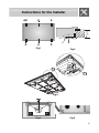
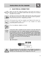
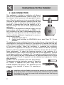
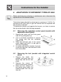
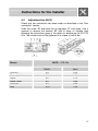
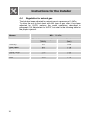
Contents
1
INSTRUCTIONS FOR SAFE AND PROPER USE _____________________ 4
2
INSTRUCTIONS FOR DISPOSAL – OUR ENVIROMENTAL CARE _______ 7
3
POSITIONING OF THE HOB _____________________________________ 8
4
ELECTRICAL CONNECTION ____________________________________ 13
5
GAS CONNECTION ___________________________________________ 14
6
ADAPTATION TO DIFFERENT TYPES OF GAS _____________________ 16
7
FINAL OPERATIONS __________________________________________ 19
8
USING THE HOB______________________________________________ 22
9
CLEANING AND MAINTENANCE_________________________________ 25
THESE INSTRUCTIONS ARE VALID ONLY FOR END USER COUNTRIES
WHOSE IDENTIFICATION SYMBOLS APPEAR ON THE COVER OF THIS
MANUAL.
INSTRUCTIONS FOR THE INSTALLER: these are intended for the
authorized person who is to check the gas supply system and install,
commission and test the appliance.
INSTRUCTIONS FOR THE USER: these contain user advice,
description of the commands and the correct procedures for cleaning
and maintenance of the appliance.
@
Further product information is available from the website www.smeg.com
3
Precautions for Safety and Use
1
INSTRUCTIONS FOR SAFE AND PROPER USE
THIS MANUAL IS AN INTEGRAL PART OF THE APPLIANCE AND
THEREFORE MUST BE KEPT IN ITS ENTIRETY AND IN AN
ACCESSIBLE PLACE FOR THE WHOLE WORKING LIFE OF THE
COOKING HOB. WE ADVISE READING THIS MANUAL AND ALL THE
INSTRUCTIONS THEREIN BEFORE USING THE COOKING HOB.
ALSO KEEP THE SERIES OF NOZZLES SUPPLIED. INSTALLATION
MUST BE CARRIED OUT BY QUALIFIED PERSONNEL IN
ACCORDANCE WITH THE REGULATIONS IN FORCE. THIS
APPLIANCE IS INTENDED FOR DOMESTIC USES AND CONFORMS
TO CURRENT REGULATIONS IN FORCE. THE APPLIANCE HAS
BEEN BUILT TO CARRY OUT THE FOLLOWING FUNCTIONS:
COOKING AND HEATING-UP OF FOOD. ALL OTHER USES ARE
CONSIDERED IMPROPER. THE MANUFACTURER DECLINES ALL
RESPONSIBILITY FOR IMPROPER USE.
THIS APPLIANCE HAS BEEN MANUFACTURED TO COOK FOOD, DO
NOT USE THE APPLIANCE TO HEAT ROOMS.
TO BE INSTALLED ONLY BY AN AUTHORIZED PERSON.
NEVER LEAVE PACKAGING RESIDUES UNATTENDED IN THE
HOME. SEPARATE WASTE PACKAGING MATERIALS BY TYPE AND
CONSIGN THEM TO THE NEAREST SEPARATE DISPOSAL CENTRE.
REPLACED APPLIANCES MUST BE TAKEN TO A SPECIAL GARBAGE
COLLECTION CENTRE.
THE APPLIANCE MUST BE CONNECTED TO EARTH IN
COMPLIANCE WITH ELECTRICAL SYSTEM SAFETY REGULATIONS.
THE PLUG TO BE CONNECTED TO THE POWER SUPPLY LEAD AND
THE RELATIVE SOCKET MUST BE OF THE SAME TYPE AND
COMPLY WITH THE RELEVANT REGULATIONS. THE SOCKET MUST
BE ACCESSIBLE AFTER THE APPLIANCE IS BUILT IN.
NEVER DISCONNECT THE PLUG BY PULLING ON THE POWER
SUPPLY LEAD.
4
Precautions for Safety and Use
IMMEDIATELY AFTER INSTALLATION, CARRY OUT A QUICK TEST
ON THE APPLIANCE FOLLOWING THE INSTRUCTIONS PROVIDED
LATER IN THIS MANUAL. SHOULD THE APPLIANCE NOT FUNCTION,
DISCONNECT IT FROM THE SUPPLY AND CALL THE NEAREST
TECHNICAL ASSISTANCE CENTRE.
NEVER ATTEMPT TO REPAIR THE APPLIANCE YOURSELF.
AFTER EACH USE OF THE APPLIACE, ALWAYS CHECK THAT THE
CONTROL KNOBS ARE TURNED TO OFF
NEVER PLACE FLAMMABLE OBJECTS IN THE OVEN: IF IT SHOULD
ACCIDENTALLY BE SWITCHED ON, THIS MIGHT CAUSE A FIRE.
THE IDENTIFICATION PLATE, WITH TECHNICAL DATA, SERIAL
NUMBER AND MARKING IS CLEARLY VISIBLE UNDER THE CASING.
THE PLATE ON THE CASING MUST NOT BE REMOVED.
BEFORE CONNECTING THE DEVICE, MAKE SURE THAT IT HAS
BEEN REGULATED FOR THE TYPE OF GAS THAT WILL FEED IT,
CHECKING THE LABEL UNDER THE HOB.
NEVER PLACE PANS WITH BOTTOMS WHICH
PERFECTLY FLAT AND SMOOTH ON THE HOB GRIDS.
ARE
NOT
DURING USE THE APPLIANCE BECOMES VERY HOT. TAKE CARE
NEVER TO TOUCH THE HEATING ELEMENTS INSIDE THE OVEN. TO
AVOID BURNS AND SCALDS CHILDREN SHOULD BE KEPT AWAY.
INSTALL THE APPLIANCE SO THAT WHEN DRAWERS OR DOORS
OF UNITS INSTALLED AT HOB HEIGHT ARE OPENED, ACCIDENTAL
CONTACT WITH PANS ON THE HOB IS NOT POSSIBLE.
WARNING - IN ORDER TO PREVENT ACCIDENTAL TIPPING OF THE
APPLIANCE, FOR EXAMPLE BY A CHILD CLIMBING ONTO THE
OPEN OVEN DOOR, THE STABILIZING MEANS MUST BE
INSTALLED.
PLEASE
REFER
TO
INSTRUCTIONS
FOR
INSTALLATION.
NEVER USE PANS OR GRIDDLE PLATES WHICH PROJECT BEYOND
THE OUTSIDE EDGE OF THE HOB.
5
Precautions for Safety and Use
THE APPLIANCE IS NOT INTENDED FOR USE BY YOUNG CHILDREN OR
INFIRM PERSONS UNLESS THEY HAVE BEEN ADEQUATELY
SUPERVISED BY A RESPONSIBLE PERSON TO ENSURE THEY CAN USE
THE APPLIANCE SAFELY. YOUNG CHILDREN SHOULD BE SUPERVISED
TO ENSURE THAT THEY DO NOT PLAY WITH THE APPLIANCE.
DO NOT SPRAY ANY SPRAY PRODUCTS NEAR THE ELECTRICAL
APPLIANCE WHILE IT IS IN OPERATION.
DO NOT USE SPRAY PRODUCTS WHILE THE PRODUCT IS STILL HOT.
WHERE THIS APPLIANCE IS INSTALLED IN MARINE CRAFT OR
CARAVANS, IT SHALL NOT BE USED AS A SPACE HEATER.
DO NOT MODIFY THIS APPLIANCE.
DO NOT USE STEAM JETS FOR CLEANING THE APPLIANCE.
THE STEAM COULD REACH THE ELECTRONICS, DAMAGING THEM
AND CAUSING SHORT-CIRCUITS.
DO NOT STORE FLAMMABLE MATERIALS IN THE APPLIANCE
STORAGE DRAWER OR NEAR THIS APPLIANCE.
THE INSTRUCTIONS PACKAGED WITH THIS APPLIANCE CONTAIN
IMPORTANT INFORMATION ABOUT INSTALLATION AND USE.
UNSUITABLE FOR USE IN MARINE CRAFT, CARAVANS OR MOBILE
HOMES, UNLESS EACH BURNER IS FITTED WITH A FLAME
SAFEGUARD
IN CASE OF SERVICE, CONTACT YOUR NEAREST SERVICE AGENT
OR DISTRIBUTOR LISTED ON THE WARRANTY CARD.
The manufacturer declines all responsibility for injury or damage
caused by failure to comply with the above regulations or deriving from
tampering with even just one part of the appliance and the use of nonoriginal spare parts.
6
Instructions for disposal
2
ENVIROMENTAL RESPONSIBILITY
Our product's packing is made of non-polluting materials, which are
therefore compatible with the environment and recyclable. Please
help by disposing of the packaging correctly. You can obtain the
addresses of collection, recycling and disposal centres from your
retailer or from the competent local organisations.
Do not discard the packaging or any part of it, or leave it
unattended. It can constitute a suffocation hazard for children,
especially the plastic bags.
Your old appliance also needs to be disposed of correctly.
Important: hand over your appliance to the local agency authorised
for the collection of electrical appliances no longer in use. Correct
disposal enables intelligent recovery of valuable materials.
Before disposing of your appliance it is important to remove doors
and leave shelves in the same position as for use, to ensure that
children cannot accidentally become trapped inside during play. It is
also necessary to cut the connecting cable to the power grid,
removing it along with the plug.
7
Instructions for the Installer
3
POSITIONING OF THE HOB
It is the law that all gas appliances are installed by authorised
persons.
Clearance around the appliance must comply with the requirements of
AS5601.
The following operation requires building and/or carpentry work so must
be carried out by a competent tradesman. Installation can be carried
out on various materials such as masonry, metal, solid wood or plastic
laminated wood as long as they are heat resistant (T 90°C).
3.1
Attachment to support structure
Create an opening with the dimensions shown in the figure in the top
surface of the counter, keeping a minimum distance of 50 mm from the
rear border.
This appliance is classified as “type Y” in relation to fire hazards and
can therefore be mounted against walls higher than the work surface on
condition that a certain distance “X” be kept between the appliance and
the wall as shown in the figure so as to avoid damage from
overheating.
Make sure there is a minimum of 750 mm between the hot plate flames
and any shelf that may be installed directly above them.
Carefully position the insulating seal supplied on the outer perimeter of
the hole made in the counter top as shown in figure 4 (the dimensions
in the figure refer from the hole to the inside of the seal), trying to
ensure that it sticks across the whole of its surface by applying light
pressure with your hands. Fix the hob to the unit using the appropriate
brackets B and spacer A as shown in figures 1, 2 and 3. Spacer A will
help to keep the hob top at the right distance from the edge of the
counter top to avoid future overheating during operation and must be
used solely in the front left-hand corner of the appliance. Carefully
trim the surplus away from edge C beyond the seal (Fig.5).
8
Instructions for the Installer
B
B
20 ÷ 40
A+B
A
B
B
B
B
Fig.1
Fig.2
A
B
Fig.3
Fig.4
Fig.5
9
Instructions for the Installer
Overall dimensions: location of gas and electrical connection points (all
measures in mm).
A
B
C
D
A
B
C
D
60 cm
hob
35
65
30
80
3.2 Clearances above and around domestic appliances
Extract from AS5601
10
90 cm
hob
105
50
50
75
Instructions for the Installer
REQUIREMENTS
1. Overhead clearances – (Measurement A)
Range hoods and exhaust fans shall be installed in
accordance with the manufacturer’s instructions. However,
in no case shall the clearance between the highest part of
the hob of the cooking appliance and a range hood be less
than 600 mm or, for an overhead exhaust fan, 750 mm.
Any other downward facing combustible surface less than
600 mm above the highest part of the hob shall be
protected for the full width and depth of the cooking surface
area in accordance with Clause 5.12.1.2. However, in no
case shall this clearance to any surface be less than 450
mm.
2.
Side clearances – (Measurements B & C)
Where B, measured from the periphery of the nearest
burner to any vertical combustible surface, is less than 200
mm, the surface shall be protected in accordance with
Clause 5.12.1.2 to a height C of not less than 150 mm
above the hob for the full dimension (width or depth) of the
cooking surface area. Where the cooking appliance is fitted
with a ‘splashback’, protection of the rear wall is not
required.
3.
Additional requirements for Freestanding and Elevated
Cooking
Appliaces – (Measurements D & E)
Where D, the distance from the periphery of the nearest
burner to a horizontal combustible surface is less than 200
mm, then E shall be 10 mm or more, or the horizontal
surface shall be above the trivet. See insets above.
11
Instructions for the Installer
NOTES
1. Requirement 3 does not apply to a freestanding or elevated
cooking appliance which is designed to prevent flames or
the cooking vessels from extending beyond the periphery of
the appliance.
2. The ‘cooking surface area’ is defined as that part of the
appliance
3. where cooking normally takes place and does not include
those parts of the appliance containing control knobs.
4. For definition of hob, see Clause 1.4.64.
5. For definition of trivet, see Clause 1.4.109.
6. Consideration is to be given to window treatments when
located near cooking appliances. See Clause 5.3.4.
12
Instructions for the Installer
4
ELECTRICAL CONNECTION
Make sure that the voltage and capacity of the power line conform to
the data shown on the plate located under the casing. Do not remove
this plate for any reason.
The plug on the end of the supply cable and the wall socket must be
the same type and conform to the current electrical system regulations.
Check that the power line is adequately grounded.
On the power line, install an omnipolar cut-off device with contact cutoff distance greater than or equal to 3 mm, located in an easily
accessible position near the unit.
Do not use reducers, adapters or shunts.
If the power cable is replaced, the wire section on the new cable must
not be less than 1 mm 2 (3 x 1 cable), keeping in mind that the end to
be connected to the hob must have the ground wire (yellow-green)
longer by at least 20 mm. Use only H05V2V2-F cable or similar which
has a maximum temperature of 90°C. Any replacement needed should
be carried out by a specialised technician who should make the mains
connections according to the following diagram.
L = brown
N = blue
= yellow-green
The manufacturer will not be liable for any damage to persons or
property caused by non-observance of the above instructions or
deriving from the tampering of even a single part of the hob.
13
Instructions for the Installer
5 GAS CONNECTION
This appliance is suitable for installation with Natural
Gas or ULPG (propane/butane). Refer to page 12 for
the relevant burner pressure and appropriate injector
sizes. When the appliance is to be connected to Natural
Gas then the pressure regulator supplied must be fitted
to the gas inlet. A test point (for checking the gas
pressure) is supplied either with the regulator or as a
separate fitting in the case of ULPG (propane/butane)
appliances.
Connection of the appliance to the gas supply must be
in accordance with the requirements of AS5601. A ½”
BSP connector at the inlet is recommended and the gas
supply line to the appliance must be of adequate length
to allow sufficient withdrawal of appliance for service or
disconnection and be:
1. annealed copper pipe or;
2. flexible hose according to AS/NZ1869 & be at least Class “B”, 10 mm
diameter.
The appliance must be installed with provision to allow the gas to be turned off and
disconnected for servicing and removal of the appliance as required from the gas
supply. Before the appliance is operated make certain all relevant parts are placed
in the correct position. When the installation is completed the installation
connections of appliance will require to be leak tested, the burner operating
pressure and flame checked and adjusted. Warranty service calls do not cover
these adjustments! To check the operating pressure of the appliance it is
recommended at least 2 large size burners are used. Ensure appliance is secured
to wall when installation is completed. N.G. The regulator supplied must be fitted to
the ½ BSP thread at the rear of the appliance. An approved manual shut-off valve
must be installed. The N.G. regulator must be checked and adjusted to 1.0kPa
after installation.
U.L.P.G. Can be connected to the inlet fitting directly.
The pressure must be checked to ensure it is operating
at 2.75kPa. A separate test point fitting must be
installed between the piping & the appliance for the
pressure to be checked to ensure it is operating at
2.75kPa.
Installation with the flexible hose must be carried out so that the length
of the piping does not exceed 2 metres fully extended; make sure that
the hoses do not come into contact with moving parts and that they are
not crushed in any way.
14
Instructions for the Installer
5.1
Connection to liquid gas
Use a pressure regulator and make the connection on the gas cylinder
following the guidelines established by the regulations in force. Make
sure that the feed pressure complies with the values indicated in the
table at point “5.3 Burner and nozzle characteristics table”.
5.2
Room ventilation
Caution – This hob may only be installed and operated in rooms
permanently ventilated in accordance with current regulations. For
proper operation of a gas appliance it is essential for the air necessary
for combustion of the gas to be able to flow naturally into the room. Air
must flow directly into the room through openings in its outside walls.
This (these) opening (s) must have a free passage cross-section of at
least 100 cm2, or 200 cm2 for appliances not equipped with gas safety
device. These openings must be constructed so that they cannot be
obstructed indoors or outdoors, and should preferably be close to the
floor on the side opposite to the combustion gas discharge point. If it is
not possible to make the openings in the room where the cooker is
installed, the necessary air may be taken from an adjoining room,
proveded it is not a bedroom or a room with fire risk.
5.3
Combustion discharge
Combustion gases may be discharged by means of hoods connected
to a flue with reliable natural draught, or a fan extraction system. An
effective extraction system requires careful design by an authorised
specialist, and must comply with the regulation distances and positions.
After installation, the engineer must issue a certificate of compliance.
15
Instructions for the Installer
6
ADAPTATION TO DIFFERENT TYPES OF GAS
Before performing any cleaning or maintenance work, disconnect the
appliance from the electrical socket.
The hob has been adjusted for natural gas at a pressure of 1.0 kPa. For
functioning with other types of gas the nozzles must be replaced and
the primary air adjusted.
To replace the nozzles and regulate the burners, you have to remove
the top as described in the following paragraph.
6.1
1.
2.
3.
4.
6.2
1.
2.
3.
16
Removing the separable control panel (models with
separable control panel)
Remove the knobs and the knob guard
tube “A” by pulling them up;
Use a crosshead screwdriver to remove
the screws and the two cylindrical
supports “B”;
Raise the left-hand side of the control
panel slightly and shift it to the right to
remove it completely;
In models with electric hotplate, the body
of the pilot light has to be removed to free
the control panel;
Removing the hob (models with integrated control
panel)
Remove the knobs, the
griddles, the burner caps, the
flame caps and the two rear
plugs;
Remove the screws “A”
which fix the burner supports;
Raise the hob, sliding it off
the ignition plugs and/or the
thermocouples and the gas
tap rods;
Instructions for the Installer
6.3
Adjustment for ULPG
Check that the connection has been made as described in the “Gas
connection” section.
Undo the screw “D” and push the air regulator “C” fully down. Use a
spanner to remove the nozzles “B” and fit those of suitable type
following the instructions given in the tables for bottled gas ULPG 2.75
kPa. The nozzle must not be tightened to a torque of over 3 Nm.
Burner
Auxiliary
Semi rapid
Rapid
Rapid Large
Fish Pan
Wok
ULPG – 2.75 kPa
Nominal gas consumption
(MJ/h)
4.8
5.9
8.6
9.5
9.5
15.0
Injector
(mm)
0.60
0.65
0.78
0.85
0.85
1.05
17
Instructions for the Installer
6.4
Regulation for natural gas
The hob has been adjusted for natural gas at a pressure of 1.0kPa.
To allow the unit to work back with this type of gas, after it has been
adjusted for ULPG, perform the same operations described in
paragraph “5.3 Adjustment for ULPG”, but refer to the following table for
the proper injectors.
Burner
Auxiliary
Semi rapid
Rapid
Rapid Large
Fish Pan
Wok
18
NG – 1.0 kPa
Nominal gas consumption
(MJ/h)
4.8
5.9
8.6
11.4
11.4
15.0
Injector
(mm)
0.98
1.10
1.25
1.50
1.50
1.70
Instructions for the Installer
7
FINAL OPERATIONS
Having carried out the above adjustments, reassemble the appliance
following, backwards, the instructions in paragraph “5.1 Removing the
separable control panel / 5.2 Removing the hob”.
7.1
Regulation of minimum for natural gas
Light the burner and take it to the minimum .
Remove the gas tap knob and turn the
adjustment screw at the side of the tap shaft
until there is a regular minimum flame. Replace
the knob and check burner flame stability:
(rapidly turning the knob from maximum to
minimum position, the flame should not go out).
Repeat the operation on all the gas taps.
19
Instructions for the Installer
7.2
Arrangement of the burners on the hob (Hob with
separable control panel)
60 cm. hob
BURNERS
1.
2.
3.
4.
5.
Auxiliary
Semirapid r
Semirapid l
Rapid large
Wok
90 cm. hob
BURNERS
1.
2.
3.
4.
5.
20
Auxiliary
Semirapid
Rapid
Fish burner
Wok
Instructions for the Installer
7.3
Arrangement of the burners on the hob (Hob with
built-in control panel).
60 cm. hob
BURNERS
1.
2.
3.
4.
5.
7.4
Auxiliary
Semirapid r
Semirapid l
Rapid
Wok
Lubrication of gas taps
With time it may happen that the gas taps get blocked and hard to turn.
Clean them inside and re-grease them. This operation must be done
by an authorised person.
21
Instructions for the user
8
USING THE HOB
Before turning on the burners, make sure that the burner rings, caps
and grids have been fitted correctly.
In the ultrarapid burner, notch A must be aligned with pin B.
Grid C provided is intended for use with woks (Chinese pans).
Adapter D comes only with open grids models and is intended for use
with small sized vessels.
8.1
Ignition of the burners
The device is fit with electronic ignition. Simply press and
simultaneously turn the knob counter-clockwise on the low point flame
symbol, until the burner is ignited. In models with safety valve, the knob
has to be turned to the ignition symbol before it is pressed, and after
ignition the knob has to be kept pressed for about 2 seconds to keep
the flame lit and to activate the safety device.
The burner might go off when the knob is released. In this case repeat
the aforesaid operation keeping the knob pressed for more than 2
seconds.
Should the burners go off accidentally in the models with valves, a
safety device will trip after approximately 20 seconds to block the gas
outlet even if the cock is open.
8.2
Practical advice for using the burners
For better burner performance and minimum gas
consumption, flat bottomed, even pans must be used,
with covers and proportional in size to the burners (see
paragraph “7.3 Diameter of the pans”).
To avoid overcooking or damage to the surface top
22
Instructions for the user
while cooking, all pans or griddles must be positioned
within the cooking hob perimeter and must be a
minimum distance of 3-4 cm from the knobs.
8.3
Diameter of the pans
Burners
Ø min. and max. (en cm.)
Auxiliary
12-14
Semirapid
16-20
Rapid medio
22-26
Rapid large
22-26
Ultrarapid
22-26
Fish burner
8.4
Special oval-shaped vessels
Electric elements
8.4.1 Turning on electric elements
Hobs may be fitted with an electric element of varying
diameter. The electric element is controlled by a switch
and is turned on by rotating the appropriate knob to the
desired position.
8.4.2 Using the electric elements
The settings shown in the table are merely indicative.
POSITION
HEAT
INTENSITY
POSSIBLE COOKING
0
Off
1
Wreak
To melt butter, chocolate, etc.
To heat small amounts of liquid.
2
Soft
To heat larger amounts of liquid.
3
Slow
To defrost frozen food and prepare
stews, cooking at or just below
boiling point.
23
Instructions for the user
4
Medium
To cook food which has to reach
boiling point, to roast delicate meat
or fish.
5
Strong
For roasts, steaks and large boiled
joints.
6
Very strong
To boil large amounts of water, to
fry.
WARNING
When switching on the electric element for the
first time, or if the electric element has not been
used for a long time, to remove any humidity
from the insulating material it should be dried
out by placing the electric element on position 1
for 30 minutes.
To use correctly remember to:
•
Switch the electric element only after having placed the pan on it.
•
Use flat and thick bottomed pans.
•
Never use pans which are smaller than the electric element.
•
Dry the bottom of the pan before placing it on the electric element.
•
When cooking with flammable oils and fats, never leave the
appliance.
•
The electric elements will stay hot for a long time after use: do not
touch them or place any objects on them.
•
If any dents appear in the electric element surface, switch it off
immediately and contact the nearest authorised servicing centre.
•
Never place sheets of aluminium foil directly on the surface of the
hotplate.
24
Instructions for the user
9
CLEANING AND MAINTENANCE
Never use a steam jet to clean the appliance.
Before any intervention, disconnect the power supply of the device.
9.1
Cleaning
Clean the cooking top regularly every time you use it, obviously after it
has cooled.
9.1.1 Regular daily cleaning of the hob
In order to clean and preserve the surface, always use specific
products only, which do not contain abrasive substances or chlorinebased acid substances.
How to use: pour the product on a damp cloth and wipe the surface,
rinse thoroughly and dry with a soft cloth or deerskin.
9.1.2 Food stains or residues
Do not use metallic sponges or sharp scrapers: they will
damage the surface.
Use normal non-abrasive products and remove spots or
residuals with non-scratch sponges or, if need be, with wood
or plastic utensils.
Rinse thoroughly and dry with a soft cloth or deerskin.
25
Instructions for the user
9.2
Cleaning of cooking hob components
CAUTION: do not wash these components in a dishwasher.
In normal use of the hob, the stainless steel burner caps and panstands tend to be burnished by the high temperature. Clean these parts
using very fine abrasive sponges or similar commercial products. Then
use a specific paste polish to restore the steel’s shine. Your local
authorised after-sales technician is able to supply professional products
for appliance cleaning and care.
Grids, caps, flame cap crowns and burners can be
removed for ease of cleaning. Wash them in warm
water using a non-abrasive detergent, taking care to
remove all tough spots. Before remounting, allow the
components to fully dry out. In fact, humidity residues
inside the burner holes might impair burner operation.
9.2.1 Ignition plugs and safety devices
For good functioning of the lighting ignition plugs and the safety
devices, keep them very clean.
Check frequently and clean with a damp cloth when necessary.
9.2.2 The electric element
After use, to make sure that the surfaces are clean and long lasting, the
electric element must be treated with specific cleaning products which
are available on the market. This necessary operation prevents
oxidisation (rust formation).
9.2.3 The cover
Clean the glass or steel cover, where mounted, with warm water. Never
use abrasive sponges or detergents.
Never lower the cover when burners or electric elements are on or
still hot.
Attention: the glass lid may break if overheated. Make sure that all the
burners are switched off and let them cool down before lovering the lid.
26
Instructions for the user
9.2.4 Preventive maintenance
This appliance does not need any special maintenance. However, a
few simple operations have to be carried out periodically to prevent
malfunctioning:
Burners: the burners must be cleaned periodically to ensure correct
combustion; make sure that all the openings and flame ports are clean
and free of obstacles, and that the burners rest firmly on their supports.
Gas connection: the gas connection must be checked periodically.
Flexible pipes: if a flexible pipe is used, it must be inspected
periodically (once a year) for leakages: if the surface of the pipe
appears rigid and cracked, disconnect immediately the cooker from the
gas supply and replace the pipe with a new one.
Valves: if the gas valves get stuck or hard to turn, they need to be
cleaned and re-greased; this operation must be carried out by an
authorised person.
27
Instructions for the user
9.3
PROBLEMS AND CAUSES
Each of the following cases is caused by an abnormal operation of the
appliance and should be dealt with by a authorised persons: please
contact your local dealer or Service Center in case you detect any of
these malfunctioning.
PROBLEM
The flame is very long with
bright yellow tips.
Black deposits on the
bottom of the pans.
The flame is very short
and
noisy. The flame moves
away from the burner
ports.
The flame extinguishes
when the burner knob is
set to the low flame
position.
The valve knob is hard to
rotate.
28
CAUSE
Defect of comburent air or
incorrect injectors.
Burner dirty or flame ports
obstructed.
Excess of comburent air.
WHAT TO DO
Clean the burner.
Call Service Center if the
problem remains.
Call Service Center.
Incorrect adjustment of the Call Service Center.
minimum heat input or
excess of comburent air.
Gas valve worn out or Call Service Center.
needs lubrification.
914773237/ E