1
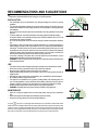
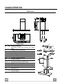
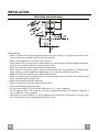
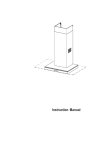
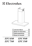
Instructions Manual
SHWL900S - SHWL900B
INDEX
EN
RECOMMENDATIONS AND SUGGESTIONS ..................................................................................................................... 3
CHARACTERISTICS ............................................................................................................................................................. 4
INSTALLATION...................................................................................................................................................................... 5
USE ........................................................................................................................................................................................ 8
MAINTENANCE ..................................................................................................................................................................... 9
2
2
RECOMMENDATIONS AND SUGGESTIONS
The Instructions for Use apply to several versions of this appliance. Accordingly, you may find
descriptions of individual features that do not apply to your specific appliance.
INSTALLATION
• The manufacturer will not be held liable for any damages resulting from incorrect or improper
installation.
• The minimum safety distance between the cooker top and the extractor hood is 650 mm (some
models can be installed at a lower height, please refer to the paragraphs on working dimensions
and installation).
• Check that the mains voltage corresponds to that indicated on the rating plate fixed to the inside of
the hood.
• For Class I appliances, check that the domestic power supply guarantees adequate earthing.
Connect the extractor to the exhaust flue through a pipe of minimum diameter 120 mm. The route
of the flue must be as short as possible.
• Do not connect the extractor hood to exhaust ducts carrying combustion fumes (boilers, fireplaces,
etc.).
• If the extractor is used in conjunction with non-electrical appliances (e.g. gas burning appliances), a
sufficient degree of aeration must be guaranteed in the room in order to prevent the backflow of
exhaust gas. The kitchen must have an opening communicating directly with the open air in order
to guarantee the entry of clean air. When the cooker hood is used in conjunction with appliances
supplied with energy other than electric, the negative pressure in the room must not exceed 0,04
mbar to prevent fumes being drawn back into the room by the cooker hood.
• In the event of damage to the power cable, it must be replaced by the manufacturer or by the
technical service department, in order to prevent any risks.
“WARNING: Failure to install the screws or fixing device in accordance with these instructions may
result in electrical hazards.”
2°
USE
•
•
•
•
•
•
•
•
•
The extractor hood has been designed exclusively for domestic use to eliminate kitchen smells.
Never use the hood for purposes other than for which it has been designed.
Never leave high naked flames under the hood when it is in operation.
Adjust the flame intensity to direct it onto the bottom of the pan only, making sure that it does not
engulf the sides.
Deep fat fryers must be continuously monitored during use: overheated oil can burst into flames.
Do not flambè under the range hood; risk of fire
This appliance is not intended for use by persons (including children) with reduced physical, sensory or mental capabilities, or lack of experience and knowledge, unless they have been given supervision or instruction concerning use of the appliance by a person responsible for their safety.
Children should be supervised to ensure that they do not play with the appliance.
“WARNING: Accessible parts may become hot when used with cooking appliances.”.
MAINTENANCE
• Switch off or unplug the appliance from the mains supply before carrying out any maintenance
work.
• Clean and/or replace the Filters after the specified time period (Fire hazard).
• Clean the hood using a damp cloth and a neutral liquid detergent.
The symbol
on the product or on its packaging indicates that this product may not be treated as household waste. Instead it
shall be handed over to the applicable collection point for the recycling of electrical and electronic equipment. By ensuring this product
is disposed of correctly, you will help prevent potential negative consequences for the environment and human health, which could
otherwise be caused by inappropriate waste handling of this product. For more detailed information about recycling of this product,
please contact your local city office, your household waste disposal service or the shop where you purchased the product.
EN
3
3
CHARACTERISTICS
Dimensions
Min.
Min.
650mm 650mm
Components
Q.ty Product Components
1 Hood Body, complete with: Controls, Light, Blower,
Filters
2
1 Telescopic Chimney comprising:
2.1
1 Upper Section
2.2
1 Lower Section
9
1 Reducer Flange ø 150-120 mm
10
1 Damper ø 150
14.1
2 Air Outlet Connection Extension
15
1 Air Outlet Connection
Ref. Q.ty Installation Components
7.2.1
2 Upper Chimney Section Fixing Brackets
7.3
1 Air Outlet Connection Support
11
6 Wall Plugs
12a
6 Screws 4,2 x 44,4
12c
6 Screws 2,9 x 9,5
Q.ty Documentation
1 Instruction Manual
15
Ref.
1
EN
14.1
7.3
9
12a 7.2.1
11
10
2.1
12c
2
2.2
11
12a
1
4
4
INSTALLATION
1÷2
Wall drilling and bracket fixing
11
116 116
650 min.
12a
X
7.2.1
320
7.3
Wall marking:
• Draw a vertical line on the supporting wall up to the ceiling, or as high as practical, at the
centre of the area in which the hood will be installed.
• Draw a horizontal line at 650 mm above the hob.
• Place bracket 7.2.1 on the wall as shown about 1-2 mm from the ceiling or upper limit aligning the centre (notch) with the vertical reference line.
• Mark the wall at the centres of the holes in the bracket.
• Place bracket 7.2.1 on the wall as shown at X mm below the first bracket (X = height of the
upper chimney section supplied), aligning the centre (notch) with the vertical line.
• Mark the wall at the centres of the holes in the bracket.
• Mark a reference point as indicated at 116 mm from the vertical reference line and 320 mm
above the horizontal reference line.
• Repeat this operation on the other side.
• Drill ø 8 mm holes at all the centre points marked.
• Insert the wall plugs 11 in the holes.
• Fix the lower bracket 7.2.1 using the 12a screws (4,2 x 44,4) supplied.
• Fix the upper bracket 7.2.1 and the air outlet connection support 7.3 together using the 2
screws 12a (4,2 x 44,4) supplied.
• Insert the two screws 12a (4,2 x 44,4) supplied in the hood body fixing holes, leaving a gap
of 5-6 mm between the wall and the head of the screw.
EN
5
5
Mounting the hood body
• Before attaching the hood body, tighten the two screws Vr located on the hood body mounting points.
• Hook the hood body onto the screws 12a.
• Fully tighten the support screws 12a.
• Adjust the screws Vr to level the hood body.
Vr
12a
Connections
DUCTED VERSION AIR EXHAUST SYSTEM
When installing the ducted version, connect the hood to the
chimney using either a flexible or rigid pipe ø 150 or 120mm, the
choice of which is left to the installer.
To install a ø 150 pipe
• To install the dumper 10
• Fix the pipe in position using sufficient pipe clamps (not supplied).
To install a ø 120 pipe
• To install a ø 120 mm air exhaust connection, insert the reducer flange 9 on the dumper 10.
• Fix the pipe in position using sufficient pipe clamps (not supplied).
• Remove any activated charcoal filters.
•
•
•
•
•
RECIRCULATION VERSION AIR OUTLET
Insert the connection extension pieces laterally 14.1 in connection 15.
Insert the Connector 15 into the Support bracket 7.3 and fix it
with a screw.
Make sure that the outlet of the extension pieces 14.1 is horizontally and vertically aligned with the chimney outlets.
Connect the air outlet connection 15 to the hood body outlet
using either a flexible or rigid pipe ø 150 mm, the choice of
which is left to the installer.
Ensure that the activated charcoal filters have been inserted.
EN
ø 150
10
ø 120
9
10
7.3
14.1
15
ø 150
6
6
ELECTRICAL CONNECTION
• Connect the hood to the mains through a two-pole switch having a contact gap of at least 3 mm.
• Remove the grease filters (see paragraph Maintenance) being
sure that the connector of the feeding cable is correctly inserted
in the socket placed on the side of the fan.
Flue assembly
7.2.1
Upper exhaust flue
• Slightly widen the two sides of the upper flue and hook them
behind the brackets 7.2.1, making sure that they are well
seated.
• Secure the sides to the brackets by using the 4 screws 12c (2,9
x 9,5) supplied.
• Make sure that the outlet of the extensions pieces is aligned
with the chimney outlets.
12c
2.1
2
2.2
12c
Lower exhaust flue
• Slightly widen the two sides of the flue and hook them between the upper flue and the wall, making sure that they are
well seated.
• Fix the lower part laterally to the hood body by using the 2
screws 12c (2,9 x 9,5) supplied.
EN
7
7
USE
A
B
C
D
E
F
G
H
I
L
Control panel
Button
A
B
C
D
E
F
G
H
I
L
Function
Display
Turns the suction motor on/off.
Decreases the working speed.
Increases the working speed.
Activate intensive speed from any other speed, including motor off. This speed is set to operate for 10
minutes, after which the system returns to the speed
that was set before. Suitable to deal with maximum
levels of cooking fumes.
Press and hold the button for approximately 5 seconds, with all the loads turned off (Motor and Lights),
to turn the Activated Charcoal Filter alarm On and
Off.
24H function
Turns the suction motor on at speed one and effects
one 10 minute extraction every hour.
Delay function
Activate automatic switch-off with a 30’ delay. Suitable to complete elimination of residual odours. Can
be activated from any position, and is disabled by
pressing the button or turning the motor off.
Press and hold the button for approximately 5 seconds, with all the loads turned off (Motor and Lights),
to turn the Remote Control On and Off.
When the filters alarm is triggered, the alarm can be
reset by pressing and holding this button for approximately 3 seconds.
These indications are only visible when the motor is
turned off.
Displays the set speed
Displays the set speed
Displays the set speed
Displays HI and the time remaining once every second.
FC+Dot (2 flashes)–Alarm On.
FC+Dot (1 flash)–Alarm Off.
Displays 24 and the dot at the bottom right flashes
once every second, while the motor is running.
It is disabled by pressing the button.
Displays the operating speed and the dot at the bottom right flashes once a second.
IR+Dot (2 flashes)–Alarm On.
IR+Dot (1 flash)–Alarm Off.
FF flashes three times.
When the procedure terminates, the indication shown
previously turns off:
FG indicates the need to wash the metal grease
filters. The alarm is triggered after the Hood has been
in operation for 100 working hours.
FC indicates the need to change the activated charcoal filters, and also to wash the metal grease filters.
The alarm is triggered after the Hood has been in
operation for 200 working hours.
Decreases the intensity of the Lighting each time the
Button is pressed, in cycle.
Turns the lighting system on and off at maximum
intensity.
Increases the intensity of the Lighting each time the
Button is pressed, in cycle.
Keyboard Lock: it is possible to lock the keyboard, for example when cleaning the Glass surface, when the
Hood has Motor and Lights turned off.
Press A for approximately 5 Seconds to enable or disable the Keyboard Lock, which is always confirmed
by:
- 1 flash of “00” Keyboard lock Enabled.
- 2 flashes of “00” Keyboard lock Disabled.
EN
8
8
MAINTENANCE
Metal grease filters
They can be washed in the dishwasher, and need to be cleaned
whenever the FG sign appears on the display or at least once
every 2 months use, or more frequently if use is particularly
intensive.
Resetting the alarm signal
• Turn the Lights and the Suction Motor off.
• Press button G and hold it for at least 3 seconds (see Use
paragraph).
Cleaning the Filters
• Remove the Filters one at a time, pushing them towards the
back of the unit and at the same time pulling downward.
• Wash the Filters without bending them, and leave them to dry
completely before replacing. (If the surface of the filter
changes colour as time goes by, this will have absolutely no
effect on the efficiency of the filter itself.)
• Replace, taking care to ensure that the handle faces forwards.
EN
9
9
Activated Charcoal Filter (Recirculation Version)
It cannot be washed or regenerated, and must be changed when the FC symbol on the display
appears, or at least once every 4 months. The Alarm signal, if it has been activated, only
appears when the Suction motor is turned on.
Activating the alarm signal
• In Recirculation Version Hoods, the Filter Saturation Alarm must be activated on
installation or at a later date.
• Turn the Lights and the Suction Motor off.
• Press D and hold for approximately 5 Seconds:
• The message FC+Puntino flashes twice, A.C. Filter saturation alarm ACTIVATED
• The message FC+Puntino flashes once, A.C. Filter saturation alarm DEACTIVATED
CHANGING THE ACTIVATED CHARCOAL FILTER
Resetting the alarm signal
• Turn the Lights and the Suction Motor off.
• Press button G and hold it for at least 3 seconds (see Use paragraph).
Changing the Filter
• Remove the metal grease filters.
• Remove the saturated activated carbon filter by releasing the
fixing hooks.
• Fit the new filter by hooking it into its seating.
• Refit the metal grease filters.
Lighting
LIGHT REPLACEMENT
20 W halogen light.
• Remove the snap-on lamp cover by levering it from under the
metal ring, supporting it with one hand.
• Remove the halogen lamp from the lamp holder by pulling
gently.
• Replace the lamp with a new one of the same type, making
sure that you insert the two pins properly into the housings on
the lamp holder.
• Replace the snap-on lamp cover.
EN
1
10
436006002_ver2