1
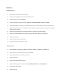
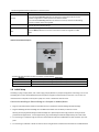
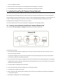
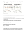
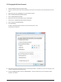
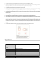
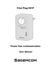
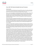
User Manual PL500EW 500Mbps HomePlug AV 2-Port Wireless Range Extender Safety CE This equipment is in compliance with the requirements of the following regulations: CE Mark, 89/336/EEC Features HomePlug Features Power voltage range is 100 to 240 V AC 50-60Hz. Support the HomePlug AV protocol and the IEEE1901 protocol. PLC physical link rate is up to 500Mbpsbps. Support the following modulation schemes: OFDM QAM 4096/1024/256/64/16/8, QPSK, BPSK, and ROBO. Support 128-bit AES link encryption and user NMK authentication, for providing secure power line communication. Support windowed OFDM with noise mitigation based on patented line synchronization technique, for improving data integrity in noisy conditions. Support channel self-adaptation and channel estimation for maximizing real-time throughput. Support priority-based CSMA/CA channel access scheme for maximizing efficiency and throughput. Support four-level QoS. Support ToS and CoS packet classifications. Support IGMP multicast management session. Wireless Features Support IEEE802.11b, IEEE802.11g, IEEE802.11n, IEEE802.3, IEEE802.3u, IEEE802.11i and IEEE802.11e. Support 2T2R mode. Transmission data rate is up to 300Mbps. Support WEP and WPA for secure data transmission. Support DHCP server. Support restoring factory default settings. Support the following wireless security modes: WEP, WPA-PSK, WPA2-PSK, and WPA/WPA2-PSK Support system status display. Support system log. 1 HomePlug Powerline HomePlug Powerline is an excellent solution that can be used to extend your network. In the home or small office building, use HomePlug Ethernet Bridges to link multiple locations without the need to run long Ethernet cables. Combined with a broadband DSL/Cable connection, every room with electrical power outlets will have easy access to high-speed Internet connection. With the HomePlug AV speed of up to 500Mbps, this easy-to-setup solution can provide fast streaming HD movies, online multiplayer games, and other data intensive activities for today’s HD Entertainment Center demand. 1.1 Introduction Each HomePlug AV Ethernet Bridge allows you to connect one device that has an Ethernet port to a Powerline network. In operation, the HomePlug AV Ethernet Bridge is completely transparent, and simply passes data between the Ethernet port and the Powerline network. Any Ethernet-enabled device may be connected to the HomePlug AV Ethernet Bridge’s Ethernet port. 1.2 System Diagram Add high-speed Internet access to any room in your home with this HomePlug AV Ethernet Bridge. You can stream HD movies and music, play online multi-player games and much more. Note: HomePlug AV Ethernet Bridge needs to pair with at least one other HomePlug AV compatible device such as this one in order to create a working system. 1.3 Casing Details Front Casing Status Lights The following table describes the status of LED indicators on the front panel: LED Indicator Power LAN1 LAN2 Data Color Green Status On Green Blink Green Green Green Green Green Orange Red Green Orange Off On Blink Off On Blink Off On On On Off Blink Blink Description System runs normally. System is resetting. System is in the process of password synchronization. Device is powered off or system is down. Connection via the LAN1 interface succeeds. Data is being transmitted via the LAN1 interface. No connection is established via the LAN1 interface. Connection via the LAN2 interface succeeds Data is being transmitted via the LAN2 interface. No connection is established via the LAN2 interface. HomePlug transmission rate equals to or is greater than 40Mbps. HomePlug transmission rate is between 20Mbps and 40Mbps. HomePlug transmission rate is smaller than or equals to 20Mbps. Device is not connected to the power line network. Wireless data is being transmitted. WPS negotiation is in progress and wireless data is being transmitted. The following table describes pushbuttons on the front panel: Button Description It is used to set the status of the device members. Press and hold the Security pushbutton for more than 10 seconds to exit the current Security network and generate a random password of network member. Press and hold the Security pushbutton for less than 3 seconds, and then the HomePlug becomes a member of the existing AVLN. Press the Reset pushbutton for more than 3 seconds and then release it. System Reset restores the factory default settings. It has the following functions: Press the WPS pushbutton for less than 3 seconds to enable the negotiation of PBC WPS mode. Interface and Switch Description The following table describes interfaces and switch on the HomePlug Interface Description LAN1 RJ45 LAN interface, for connecting a hub, switch, or computer on a LAN. LAN2 RJ45 LAN interface, for connecting a hub, switch, or computer on a LAN. OFF ON Turn on or turn off the device. 1.4 Initial Setup HomePlug is a plug and play device; user is able to plug and play without any complex configuration and settings. You can use HomePlug AV to connect networkable devices like computers and game consoles directly to each other. You can also connect devices like a computer or Blu-ray Disc™ player to a router or modem for Internet access. Connect the HomePlug AV Ethernet Bridge to a Computer or Modem/Router 1. Plug one end of the Ethernet Cable into the Ethernet Port on the bottom of the HomePlug AV Ethernet Bridge 2. Plug the HomePlug AV Ethernet Bridge into a AC Wall Power Outlet near the device you want to connect Warning: Do not plug this HomePlug AV Ethernet Bridge into a powerstrip that has surge protection. Doing so will degrade Powerline performance. For best performance, plug all HomePlug AV Ethernet Bridges directly into a wall outlet. 3. For connecting to a computer: Plug the other end of the Ethernet Cable into an OPEN Ethernet Port located on your computer. 4. For connecting to a Modem or Router for Internet access: Plug the other end of the Ethernet Cable into an OPEN Ethernet Port on your Modem or Router. 5. Make sure that the Data LED light on each HomePlug AV Ethernet Bridge turns solid green. 6. Your HomePlug AV Ethernet Bridges are now connected forming a HomePlug AV network. 2 Individual HomePlug AV Network Setup (Optional) All HomePlug AV Ethernet Bridges ship with a default security key so they will automatically link to all other HomePlug AV Ethernet Bridges sharing the same electrical lines. If there are other HomePlug AV Ethernet Bridges in the building (such as in an office or apartment building), you may want to create your own individual HomePlug AV network group so other HomePlug AV Ethernet Bridges cannot connect to your network. This section describes how to use the Security button for configuration in the following situations: 2.1 Creating a new individual HomePlug AV network (Network AB) Two unassociated Bridges (Bridge A and Bridge B) are forming a new network—Network AB The procedure is as follows: 1. Press and hold the Security button on Bridge A for no more than 10 seconds. Must release after 10 seconds. Once released, the Power light will flash. The password to Bridge A has just been erased and random security key has been generated. It must now be linked to your network to adopt the new network security key. 2. Press and hold the security button on Bridge B for 10 seconds and release it when the Power light flashes. The password to Bridge B has just been erased and random security key has been generated. It must now be linked to your network to adopt the new network security key. 3. Currently, Bridge A and Bridge B are not networked 4. Press and hold the Security button on Bridge A for 1~3 seconds then release. 5. The Power light on Bridge A starts to flash. 6. Within 120 seconds after the Power light on Bridge A starts to flash, press and hold the Security button on Bridge B for 1~3 seconds then release. 7. Both Bridge A and Bridge B are now networked together. 2.2 Adding Bridge C to existing Network AB (Network ABC) One unassociated Bridge C is added to an existing Network AB. The procedure is as follows: 8. Press and hold the Security button on Bridge C for no more than 10 seconds. Must release after 10 seconds. Once released, the Power light will flash. The password to Bridge C has just been erased and random security key has been generated. It must now be linked to your network to adopt the new network security key. 9. Press and hold the security button on Bridge A for 1~3 seconds. The Power light on Bridge A starts to flash. 10. Within 120 seconds after the Power light on Bridge A starts to flash, press and hold the security button on Bridge C for 1~3 seconds then release. 11. Bridge A, Bridge B and Bridge C are now networked to each other. 2.3 Removing Bridge B from Bridge A & C Network and join with Bridge D & E (Network BDE) The procedure is as follows: 1. Press and hold the Security button on Bridge B for no more than 10 seconds. Must release after 10 seconds. Once released, the Power light will flash. The password to Bridge B has just been erased and removes itself from Bridge A & C. 2. Press and hold the Security button on Bridge D for 1~3 seconds. 3. Within 120 seconds after the Power light on Bridge D starts to flash, press and hold the Security button on Bridge B for 1~3 seconds then release. 4. Bridge B and Bridge D are now connected to each other, which in turn becomes part of Network BDE. 2.4 Setting Up the Wireless Extender By default, the wireless parameters has been pre-configured as follows: Wireless SSID : Sineoji_PL500EW Wireless password : 1234567890 Default IP address : 192.168.33.1 To connect to the Wireless Extender, select the wireless search utility in Windows and locate “Sineoji_Pl500EW”. You will be prompted to enter the password. Enter “1234567890” and the wireless connectivity has been setup successfully. 2.5 Changing the Wireless Password 1. Plug the HomePlug directly on the power socket. 2. Connect an Ethernet cable to LAN 1 of the HomePlug and the other end to the Ethernet port of the Desktop PC or Notebook. 3. Right mouse click on the “NETWORK” icon of your Windows Desktop 4. Select “OPEN NETWORK AND SHARING CENTRE” 5. Select “CHANGE ADAPTER SETTINGS” 6. Right mouse click on the desired LAN and select “PROPERTIES”. 7. Double click on “INTERNET PROTOCOL VERSION 4(TCP/IPv4) 8. Select “USE THE FOLLOWING ADDRESS” 9. Enter the following: IP address: 192.168.33.X (where X will be any numerical value from 10 – 254) Subnet Mask: 255.255.255.0 10. Select OK and proceed to the Browser and enter the following IP address “192.168.33.1) to access the setup page. Enter “admin” as the password to access the setup. 11. Proceed to “WIRELESS SETUP” and select “WIRELESS BASIC”. Enter the passphrase you wish to change the default password. Click “APPLY”. 12. After changing the wireless password, ensure that you change the adapter settings to “OBTAIN AN IP ADDRESS AUTOMATICALLY”. 3 Troubleshooting and Disclaimer If your HomePlug AV Ethernet Bridges have difficulty communicating with each other, check the following: Try power cycling the unit by unplugging it from the wall for 10 seconds and plugging it in again. Hold the security/reset button down for more than 15 seconds to reset to default setting. The HomePlug AV Ethernet Bridge’s light will flash, the units will reset and attempt to link using default factory settings. Try plugging the HomePlug AV Ethernet Bridge into an adjacent plug. HomePlug AV Ethernet Bridges work better when plugged directly into the wall outlet. Connecting these Ethernet Bridges to a power strip or surge protector may degrade network performance or completely stop network signals. This HomePlug AV Ethernet Bridge should not be used on GFI protected outlets as some outlets will filter out HomePlug Powerline signal. This HomePlug AV Ethernet Bridge should not be used in areas with excessive heat. Certain florescent or incandescent lights are noise sources on the electrical and can degrade performance. If your building has more than one circuit breaker box, your HomePlug AV Ethernet Bridges may not be able to connect between the different circuit breaker boxes. In this case, connect one HomePlug AV Ethernet Bridge to a power outlet located on each of the circuit boxes. Connect Ethernet cable between each of the HomePlug AV Ethernet Bridges to link the different circuits together. This will allow the HomePlug AV Ethernet Bridges from different circuit breaker boxes to connect. To enter standby mode for this device, simply remove the Ethernet cable and wait about 3 minutes. 4 Specifications PLC Module Specification Chip Protocol Powerline Communication Rate Signal Band Modulation Mode Encryption Operation Mode Multicast Wi-Fi Module Specification Chip Flash Memory Qualcomm Atheros AR7420/AR1540 HomePlug AV IEEE1901 IEEE 802.3 10/100 Ethernet (100Mbps) IEEE 802.3u Fast Ethernet 500Mbps 2~68MHz Support OFDM 4096/1024/256/64/16/8-QAM, QPSK, BPSK, and ROBO 128-bit AES Support priority-based CSMA/CA channel access scheme Support IGMP management multicast session. Qualcomm Atheros AR9341 64Mbps DDR SDRAM: Protocol Wireless Frequency Range Channel Wireless Signal Rate Output Power Receiving Sensitivity Operation Mode Multiple SSID Security Authentication 256Mbps IEEE 802.11b/g/n IEEE 802.3/3x/3u 2.4 GHz~2.484 GHz 1~13 11b: 11/5.5/2/1Mbps 11g: 54/48/36/24/18/12/9/6Mbps 11n: up to 300Mbps in 40MHz mode and up to 150Mbps in 20MHz mode. 11b: 16~17 dBm 11g: 14~17 dBm 11n: 11~16 dBm 11b: 11Mbps/-84dBm 11g: 54Mbps/-75dBm 11n: 300Mbps/-64dBm 2Tx/2Rx Up to 4 BSSIDs WEP, WPA-PSK, WPA2-PSK, and WPA/WPA2-PSK SSID hiding MAC address access control list System Specification LED Indicator Power Socket Ethernet Port Antenna Button Consumption Environment Requirements Operating Temperature Storage Temperature Operating Humidity Storage Humidity Rated Input Physical Characteristics Dimension Weight Power: Indicate power status. LAN1: Indicate the connection status of LAN1 interface. LAN2: Indicate the connection status of LAN2/WAN interface. Data: Indicate Powerline Communication data rate. WPS: Indicate WPS connection status. UK Plug 2 x RJ45 for 10/100 Ethernet (Auto MDI/MDI-X) PCB-Antenna x 2 Security: Set the status of device members. Reset: Restore factory default settings. WPS: Press this pushbutton for less than 3 seconds to enable the negotiation of PBC mode. 6.5W 0~40ºC -10~70ºC 10%~85%, non-condensing 5%~90%, non-condensing 100~240 V AC, 50/60Hz L × W × H: 107mm × 62mm × 48.5mm 180g Warranty Product carried a warranty of 3 years from the date of purchase. Warranty registration can be done via online at http://www.sineoji.com/support/product-registration. Ensure a copy of the proof of purchase is submitted online during the registration process. The Warranty will not apply in respect: a. b. c. If the Product has not been installed, operated, maintained or used in accordance with the manufacturer's instructions or specifications provided with the Product; If the factory-applied serial number has been altered or removed from the Product; Which has suffered damage, malfunction or failure resulting from alterations, any alterations (hardware or software), accident, misuse, abuse, fire, liquid spillage, use on an incorrect voltage, power surges and dips, thunderstorm activity, force majeure, voltage supply problems, tampering or unauthorized repairs by any persons, use of defective or incompatible accessories, the operation of a computer virus of any kind. d. e. To any third-party software or hardware not contained in the Product as originally configured by the manufacturer; To service and support of any software operating system or application installed on any Product, except to assist in restoring the Product to its factory default settings; or To the full extent permitted by law: Sineoji will not be liable for any loss, damage or alterations to third party hardware, software, programs, data and/or information stored on any media or any part of the Product, no matter how occurring; or for any loss or damage arising from loss of use, loss of profits or revenue, or for any resulting indirect or consequential loss or damage. Sineoji aggregate liability in respect of all claims under the Standard Warranty shall not exceed the original purchase price of the Product or, at Sineoji’s discretion, replacement of the Product with a like or similar Product. Technical support Mail Skype Tel Website : [email protected] : tech.sineoji : +65-63392591 : www.sineoji.com