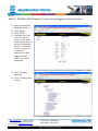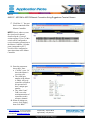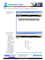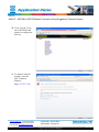
1
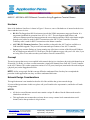
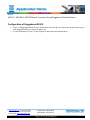
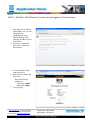
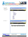
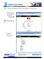
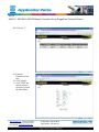
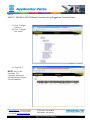
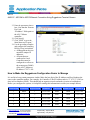
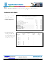
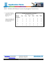
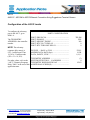
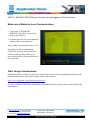
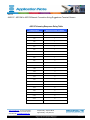
Reference: AN2107
Date: 10 February 2009
Product Type: ASC/2
ASC/2M to ASC/2 Ethernet Connection
Using Ruggedcom Terminal Servers
Purpose
This application note gives the necessary hardware components and a procedure to use Ethernet-type
communications to connect an ASC/2M Master Controller and four ASC/2 Local Controllers.
Introduction
There are many factors involved in a successful implementation of an Ethernet-type Communications Network.
Most of these factors are beyond the scope of this application note and are not included here. We assume that
you are knowledgeable with the various Microsoft Windows® operating systems, administrative functions, and
general LAN/WAN terminology and topologies. Figure 1 shows the basic design discussed in this document.
For more information, contact Econolite Technical Support.
Figure 1. ASC/2M to ASC/2 Ethernet Connection through Ruggedcom Terminal Servers
www.econolite.com For more information,
call or e-mail Econolite Technical Support:
800-225-6480 / [email protected]
1 of 3
Prepared By: Stephen Muth
Approved By: Gary Duncan
Rev. NC
ASC/2
AN2107: ASC/2M to ASC/2 Ethernet Connection Using Ruggedcom Terminal Servers
Hardware
Most of the hardware listed here is shown in Figure 1. However, some of the hardware is internal to the devices
shown and thus is not in view.
•
RS 910. The Ruggedcom RS910 unit meets/exceeds the NEMA temperature range specification. It is
temperature-hardened for operation from -40°C to +85°C. The unit supports both 10base-t and
100base-tx Ethernet speeds and auto negotiates the correct duplex operation. DB-9 male-female straightthrough serial cables are used for RS232 connections to the ASC/2 Local Controllers. Econolite
Telemetry cable is used for RS232 connections to the Master controller.
•
ASC/2 RS-232 Telemetry Interface. These modules are housed in the ASC/2 and are available as a
field-installable upgrade. They meet all environmental specifications of our ASC/2 controller.
•
Laptop. Any common Desktop or Laptop running any of the latest versions of the Microsoft Windows
OS, an Ethernet port and an RS-232 serial port. (Set the IP address to agree with your LAN. Also, if you
are using XP or Vista, make sure that your windows firewall is turned OFF.)
Concept
The major concept that we try to accomplish in this network design is to simulate a physical serial channel on an
IP network. To do this, we create a socket connection (virtual serial channel) from each ASC/2 Local Controller
to the ASC/2 Master. This socket connection consists of a TCP port (virtual port) associated with each serial port
(physical port) on the Ruggedcom RS910s.
NOTE: At first, most people find this concept difficult to understand. But, after they have completed the
procedure in this application note, they are able to understand this better.
Network Design Considerations
This application note is not intended to describe all of the variables that go into network design.
If you need design assistance in this area, please call your Econolite sales representative, and he/she will make
arrangements.
NOTES:
•
All devices on an Ethernet network must contain a unique IP address. But the Subnet mask must be
identical on each device.
•
This application note assumes that you know how to set up a master-local communications serial
channel, and so that procedure is not given here.
www.econolite.com For more information,
call or e-mail Econolite Technical Support:
800-225-6480 / [email protected]
2 of 3
Prepared By: Stephen Muth
Approved By: Gary Duncan
Rev. NC
ASC/2
AN2107: ASC/2M to ASC/2 Ethernet Connection Using Ruggedcom Terminal Servers
Configuration of Ruggedcom RS910
1. There is a Ruggedcom manual on the CD that ships with each unit; use instructions in this manual to give
each Ruggedcom RS910 a unique IP address set.
2. Use the illustration in Figure 1 of this application note and connect the hardware.
www.econolite.com For more information,
call or e-mail Econolite Technical Support:
800-225-6480 / [email protected]
3 of 3
Prepared By: Stephen Muth
Approved By: Gary Duncan
Rev. NC
ASC/2
AN2107: ASC/2M to ASC/2 Ethernet Connection Using Ruggedcom Terminal Servers
3. Now that each switch has
an IP address set, you can
start particular
configuration. Open
Internet Explorer and
enter the IP address of the
first RS910.
4. If you see a screen like
this, click “Continue to
this website”.
5. A screen similar to this
comes into view.
6. Enter the User Name and
Password.
The present factory
settings are:
Username: admin
Password: admin
7. Click [Login].
www.econolite.com For more information,
call or e-mail Econolite Technical Support:
800-225-6480 / [email protected]
4 of 3
Prepared By: Stephen Muth
Approved By: Gary Duncan
Rev. NC
ASC/2
AN2107: ASC/2M to ASC/2 Ethernet Connection Using Ruggedcom Terminal Servers
8. Click “Serial
Protocols.”
9. Click “Configure
Serial Ports.”
10. Click Port “1.”
www.econolite.com For more information,
call or e-mail Econolite Technical Support:
800-225-6480 / [email protected]
5 of 3
Prepared By: Stephen Muth
Approved By: Gary Duncan
Rev. NC
ASC/2
AN2107: ASC/2M to ASC/2 Ethernet Connection Using Ruggedcom Terminal Servers
11. Enter the Parameters
listed here for Port 1.
12. Click [Apply].
13. Click “Back.”
14. Configure Port 2 the
same way as Port 1
except, in the “Name”
field, enter the name of
the Local controller to
which it is connected.
For our example, it is
“Controller1".
Remember to click
[Apply] and then
“Back” to go to the
Main menu.
15. Click “Configure
Protocols.”
16. Click “Configure Raw
Socket”
www.econolite.com For more information,
call or e-mail Econolite Technical Support:
800-225-6480 / [email protected]
6 of 3
Prepared By: Stephen Muth
Approved By: Gary Duncan
Rev. NC
ASC/2
AN2107: ASC/2M to ASC/2 Ethernet Connection Using Ruggedcom Terminal Servers
17. Click Port “1,” the port
that is connected to the
Master Controller.
NOTE: Here is where we start
the virtual serial channel
described in the “Concept”
section on Page 2. Port 1 of this
switch will be configured to
receive incoming connections to
the Master Controller. All other
ports (connected to ASC/2
Locals) will be configured to
start connections to the Master
Controller.
18. Enter the parameters
shown here. Note:
• “Call Dir” set to “In”
shows the Master is
receiving calls.
• The virtual port
number of the Master
is 50000. All Local
controllers will talk to
this port and will
have a unique port
number.
• The “Max Conns”
field is set to the
maximum number of
controllers on this
telemetry channel.
19. When all settings are
correct, click [Apply],
then click “Back.”
www.econolite.com For more information,
call or e-mail Econolite Technical Support:
800-225-6480 / [email protected]
7 of 3
Prepared By: Stephen Muth
Approved By: Gary Duncan
Rev. NC
ASC/2
AN2107: ASC/2M to ASC/2 Ethernet Connection Using Ruggedcom Terminal Servers
20. Click Port “2” to start
the configuration for
that port.
21. Enter the parameters
shown here. Note:
• “Call Dir” set to
“Out” makes a
socket connection, as
mentioned in the
“Concept” section
on Page 2.
• “Max Conns” is only
“1”. This controller
will only talk with
the Master.
• The Remote Port is
set to that of the
Master Controller.
• The “IP Address” is
set to that of that
Master Controller.
22. When all settings are
correct, click [Apply],
then click “Back.”
www.econolite.com For more information,
call or e-mail Econolite Technical Support:
800-225-6480 / [email protected]
8 of 3
Prepared By: Stephen Muth
Approved By: Gary Duncan
Rev. NC
ASC/2
AN2107: ASC/2M to ASC/2 Ethernet Connection Using Ruggedcom Terminal Servers
23. Click “Log out” to log
out of this RS910 and
prepare to configure the
next one.
24. To continue with this
example, enter this
URL in Internet
Explorer:
https://172.27.1.202
www.econolite.com For more information,
call or e-mail Econolite Technical Support:
800-225-6480 / [email protected]
9 of 3
Prepared By: Stephen Muth
Approved By: Gary Duncan
Rev. NC
ASC/2
AN2107: ASC/2M to ASC/2 Ethernet Connection Using Ruggedcom Terminal Servers
25. Enter the User Name
and Password. If you
did not change them,
they should be:
Username: admin
Password: admin
NOTE: Most of the steps that
follow are a repeat of the steps
above.
26. Click “Serial
Protocols.”
27. Click “Configure
Serial Ports.”
www.econolite.com For more information,
call or e-mail Econolite Technical Support:
800-225-6480 / [email protected]
10 of 3
Prepared By: Stephen Muth
Approved By: Gary Duncan
Rev. NC
ASC/2
AN2107: ASC/2M to ASC/2 Ethernet Connection Using Ruggedcom Terminal Servers
28. Click Port “1”.
29. Enter the
Parameters listed
here.
30. Click [Apply].
31. Click “Back” the
number of times
necessary to reach
the Main Menu.
www.econolite.com For more information,
call or e-mail Econolite Technical Support:
800-225-6480 / [email protected]
11 of 3
Prepared By: Stephen Muth
Approved By: Gary Duncan
Rev. NC
ASC/2
AN2107: ASC/2M to ASC/2 Ethernet Connection Using Ruggedcom Terminal Servers
32. Click “Configure
Protocols.”
33. Click “Configure
Raw Socket”
34. Click Port “1”.
NOTE: Port 2 is not
listed here. The
remaining instructions
will only include one port
for each controller.
www.econolite.com For more information,
call or e-mail Econolite Technical Support:
800-225-6480 / [email protected]
12 of 3
Prepared By: Stephen Muth
Approved By: Gary Duncan
Rev. NC
ASC/2
AN2107: ASC/2M to ASC/2 Ethernet Connection Using Ruggedcom Terminal Servers
35. Enter the parameters shown
here. Note that the “Remote
Port” and
“IP address” fields point at
the ASC/2 Master
controller.
36. Click [Apply].
37. Click “Back” to go to the
Main Menu and “Logout.”
38. Use the preceding examples
and configure the remaining
RS910s. Keep in mind that:
• All Ruggedcom devices
must have unique IP
addresses
• All ports that are
connected to Local
Controllers must be
configured to call out to
the remote port (50000)
of the ASC/2 Master at
IP address 172.27.1.201.
How to Make the Ruggedcom Configuration Easier to Manage
It is useful to keep certain parameters similar. Make the last digit of the IP Address and Port Numbers the
same as the controller number. For example, for Controller 2, the IP Address ends in “2” (172.27.1.202) as
does its Port Number (50002). This should help to organize records and makes it easier to troubleshoot.
Before you configure the system, it is helpful to catalog this information in a table (see example below).
Intersection#
Controller#
Physical Port#
IP address
Local Port #
Remote Port #
Remote IP
1
Master
1
172.27.1.201
50000
50000
172.27.1.201
1
1
2
172.27.1.201
50001
50000
172.27.1.201
2
2
1
172.27.1.202
50002
50000
172.27.1.201
3
3
1
172.27.1.203
50003
50000
172.27.1.201
4
4
1
172.27.1.204
50004
50000
172.27.1.201
www.econolite.com For more information,
call or e-mail Econolite Technical Support:
800-225-6480 / [email protected]
13 of 3
Prepared By: Stephen Muth
Approved By: Gary Duncan
Rev. NC
ASC/2
AN2107: ASC/2M to ASC/2 Ethernet Connection Using Ruggedcom Terminal Servers
Configuration of the Master
1. To configure the ASC/2M
telemetry settings, go to
MM-1-0-9.
TELEMETRY SETUP AND OPTIONS
2. Enter the settings shown.
TELEMETRY SETUP
CH1
DATA RATE (bps)................................................. 19.2K
DATA FRAMING (parity, stop) ............................ 8,N,1
COMMANDS / SECOND .....................................
25
COMMAND TIME ................................................
724
WINDOW ..............................................................
80
BUFFER LEVEL ...................................................
3
RTS TO CTS DELAY ...........................................
0
TRANSMIT TIME ................................................
0
3. To enable devices in the
ASC/2M, go to MM-1-0-2.
You will probably have more
settings here because of more
locals than this example.
DEVICE#
1........
2........
3........
4........
5........
6........
7........
8........
www.econolite.com For more information,
call or e-mail Econolite Technical Support:
800-225-6480 / [email protected]
14 of 3
SYSTEM
DET.
.
.
.
.
ENABLE DEVICES
CONT.
SPEED
TRAP
x
.
x
.
x
.
x
.
x
x
x
x
.
.
.
.
CH2
****
****
****
****
****
****
****
****
TELEM.
CHAN.
x
.
.
.
.
.
Prepared By: Stephen Muth
Approved By: Gary Duncan
Rev. NC
ASC/2
AN2107: ASC/2M to ASC/2 Ethernet Connection Using Ruggedcom Terminal Servers
4. To set up the Telemetry
Sequence for Channel 1 in
the ASC/2M, go to
MM-1-0-3.
Again, your settings will
probably be different for
your application.
LOCAL
TELEM
ADDRESS
1...
2...
3...
4...
5...
6...
www.econolite.com For more information,
call or e-mail Econolite Technical Support:
800-225-6480 / [email protected]
15 of 3
TELEMETRY SEQUENCE CHANNEL 1
(See HELP for caution.)
CTR
AUX
SDA1
SDA2
SDB1
1-24
1-24
1-32
1-32
1-32
SDB2
1-32
1
2
3
4
1
2
3
4
1
2
3
4
0
0
0
0
0
0
0
0
0
0
0
0
0
0
0
0
0
0
0
0
0
0
0
0
Prepared By: Stephen Muth
Approved By: Gary Duncan
Rev. NC
ASC/2
AN2107: ASC/2M to ASC/2 Ethernet Connection Using Ruggedcom Terminal Servers
Configuration of the ASC/2 Locals
To configure the telemetry
port in the ASC/2, go to
MM-1-6.
PORT3 CONFIGURATION
The TELEMETRY
ADDRESS is the controller
number.
PORT3 PROTOCOL ...................................................
PORT3 ENABLE ........................................................
PORT3 MILISEC TIMING ........................................
PORT3 RTS TO CTS DELAY ...................................
PORT3 RTS TURN-OFF DELAY .............................
TELEM
YES
NO
0
0
NOTE: The telemetry
response delay metric is
922= 1 millisecond. Thus
19,362 is 21 milliseconds
(922 x 21 = 19,362).
DUPLEX — HALF or FULL ......................................
MODEM DATA RATE (bps) .....................................
DATA, PARITY, STOP .................... .........................
FULL
19.2K
8, N, 1
TELEMETRY ADDRESS ..........................................
SYSTEM DETECTOR 9 – 16 ADDRESS .................
For other values, refer to the
TELEMETRY RESPONSE DELAY ..........................
“ASC/2 Telemetry Response
Delay Table” at the end of this ADDITIONAL SCREEN(S) .......................................
application note.
(?)
0
19362
www.econolite.com For more information,
call or e-mail Econolite Technical Support:
800-225-6480 / [email protected]
16 of 3
Prepared By: Stephen Muth
Approved By: Gary Duncan
Rev. NC
ASC/2
AN2107: ASC/2M to ASC/2 Ethernet Connection Using Ruggedcom Terminal Servers
Make sure of Master-to-Local Communications
1. To go to the “TELEMETRY
RESPONSE STATUS” screen, in the
master, go to MM-3-6.
2. If all has gone well, the screen should be
similar to the screen shown here.
Notice (make sure) that packet loss is <1%.
Depending on your communications
architecture, you may want to adjust the
telemetry response delay (either up or
down) in the locals to get the packet loss as
low as possible.
Other Design Considerations
Ruggedcom builds a number of serial device servers that can be used to accomplish this task and may be
better than the products used in this example. Refer to their website:
http://www.ruggedcom.com/products/ruggedservers/
For more assistance with design considerations and product selection, please contact your Econolite sales
Representative.
www.econolite.com For more information,
call or e-mail Econolite Technical Support:
800-225-6480 / [email protected]
17 of 3
Prepared By: Stephen Muth
Approved By: Gary Duncan
Rev. NC
ASC/2
AN2107: ASC/2M to ASC/2 Ethernet Connection Using Ruggedcom Terminal Servers
ASC/2 Telemetry Response Delay Table
Delay metric
Amount of time in msec
0
0
922
1
1844
2
2766
3
3688
4
4610
5
5532
6
6454
7
7376
8
8298
9
9220
10
10142
11
11064
12
11986
13
12908
14
13830
15
14752
16
15674
17
16596
18
17518
19
18440
20
19362
21
20284
22
21206
23
22128
24
23050
25
www.econolite.com For more information,
call or e-mail Econolite Technical Support:
800-225-6480 / [email protected]
18 of 3
Prepared By: Stephen Muth
Approved By: Gary Duncan
Rev. NC