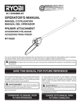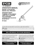
1
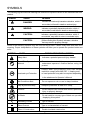
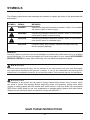
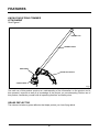
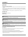
10A ELECTRIC
POWER HEAD
21142
Owner’s Manual
TOLL-FREE HELPLINE: 1-888-90WORKS (888.909.6757)
Read all safety rules and instructions carefully before operating this tool.
CONTENTS
Introduction .......................................................................................................................... 2
General Safet y Instr uction...............................................................................3 - 5
Symbols ............................................................................................................................ 6 -7
Electrical .............................................................................................................................. 8
Features ............................................................................................................................8 - 9
Assembly ........................................................................................................................ 9 -12
Operation .......................................................................................................................12-16
Maintenance ................................................................................................................. 16 -17
Troubleshooting ................................................................................................................. 17
Warranty. ........................................................................................................................... 1 8
Exploded view and Part list ........................................................................................... 19 -20
SPECIFICATIONS
10A ELECTRIC POWER HEAD
Input.................................................................................120V, AC only, 60Hz, 10Amps
Weight ........................................................................................................9.9lbs(4.5kg)
O
•
OU
SP
SI
GH
•R E
REPAIR
N
BL
E , R E LIA B LE
&
T
2
GENERAL SAFETY INSTRUCTIONS
WA R N I N G
Read and understand all instructions before using this product. Failure to follow all
instructions listed below may result in electric shock, fire and/or serious personal injury. Do not
use without guard and handle in place.
READ ALL INSTRUCTIONS
•For safe operation, read and understand all instructions before using this product. Follow all
safety instructions. Failure to follow all safety instructions listed below, can result in serious
personal injury
•Do not allow children or untrained individuals to use this unit.
•Check the work area before each use. Remove all objects such as rocks, broken glass, nails,
wire, or string which can be thrown or become entangled in the machine.
•Use Safety Glasses – Always wear eye protection with side shields marked to comply with ANSI
Z87.1. Failure to do so could result in objects being thrown into your eyes, resulting in possible
serious injury.
•Always wear safety glasses with side shields. Everyday glasses have only impact resistant
lenses. They are NOT safety glasses. Following this rule will reduce the risk of eye injury. Use
face mask if operation is dusty
•Dress Properly – Use rubber gloves and substantial footwear is recommended when working
outdoors. Wear heavy long pants, long sleeves, boots, and gloves. Do not wear loose-fitting
clothing, short pants, sandals, jewelry of any kind, or go barefoot.
•Secure long hair above shoulder level to prevent entanglement in moving parts.
•Keep children away – Keep all bystanders, children, and pets at least 50 ft. away.
•Stay alert – Do not operate this unit when you are tired, ill, or under the influence of alcohol,
drugs, or medication.
•Do not operate in poor lighting.
•Keep all parts of your body away from any moving part.
•Do not operate power tools in explosive atmospheres, such as in the presence of flammable
liquids, gases, or dust. Power tools create sparks which may ignite the dust or fumes.
•To reduce the risk of electric shock, this tool has a polarized plug (one blade is wider than the
other) and will require the use of a polarized extension cord. The plug will fit into a polarized
extension cord only one way. If the plug does not fit fully into the extension cord, reverse the
plug. If the plug still does not fit, obtain a correct polarized extension cord. A polarized extension
cord will require the use of a polarized wall outlet. This plug will fit into the polarized wall outlet
only one way. If the plug does not fit fully into the wall outlet, reverse the plug. If the plug still
does not fit, contact a qualified electrician to install the proper wall outlet. Do not change the
equipment plug, extension cord receptacle, or extension cord plug in any way.
•Avoid body contact with grounded surfaces such as pipes, radiators, ranges, and refrigerators.
There is an increased risk of electric shock if your body is grounded.
•Avoid Dangerous Environments – Don’t expose power tools to rain or wet conditions. Water
entering a power tool will increase the risk of electric shock.
3
GENERAL SAFETY INSTRUCTIONS
•Warning – To reduce the risk of electric shock - Use outdoor extension cords marked W-A, W,
SW-A, SOW-A, STW-A, STOW-A, SJW-A, SJTW-A, or SJTOW-A. These cords are rated for
outdoor use and reduce the risk of electric shock.
•Ground Fault Circuit Interrupter (GFCI) protection should be provided on the circuit(s) or
outlet(s) to be used for the gardening appliance. Receptacles are available having built-in GFCI
protection and may be used for this measure of safety.
•Use Right Appliance - Do not force tool. Use the correct tool for your application. The correct
tool will do the job better and safer at the rate for which it is designed.
•Do not operate the equipment while barefoot or when wearing sandals or similar lightweight
footwear. Wear protective footwear that will protect your feet and improve your footing on
slippery surfaces.
•Do not use on a ladder or unstable support. Stable footing on a solid surface enables better
control of the unit in unexpected situations.
•Do Not Overreach – Keep firm footing and balance. Overreaching can result in loss of balance.
•Avoid Unintentional Starting – Do not carry plugged in appliance with finger on trigger. Be sure
the switch trigger is not engaged before plugging in.
•Do not use tool if switch trigger does not turn it on or off. Any tool that cannot be controlled with
the switch trigger is dangerous and must be repaired.
•Disconnect Appliance – Remove appliance from power source before storing, servicing,
changing accessories such as cutting line. Such preventive safety measures reduce the risk of
starting the tool accidentally.
•Use only identical manufacturer’s replacement parts and accessories. Use of any other parts
may create a hazard or cause product damage.
•Maintain appliance with care – Replace string head if cracked, chipped, or damaged in any
way. Be sure the string head is properly installed and securely fastened. Keep cutting edge
sharp and clean for best performance and to reduce the risk of injury. Follow instructions for
lubricating and changing accessories. Inspect appliance cord periodically, and if damaged, have
it repaired by an authorized service facility. Inspect extension cords periodically and replace if
damaged. Keep handles dry, clean, and free from oil and grease. Failure to do so can cause
serious injury.
•Make sure all guards, straps, deflectors and handles are properly and securely attached.
•Never use flailing devices, wire, or rope on any attachment.
•Use only the manufacturer’s replacement string in the cutting head when using a string trimmer
attachment. Do not use any other cutting attachment, for example, metal wire, rope, or the like.
To install any other brand of cutting head to the string trimmer can result in serious personal
injury.
•Never operate unit without the grass deflector in place and in good condition.
•Check damaged parts – Before further use of the tool, a guard or other part that is damaged
should be carefully checked to determine that it will operate properly and perform its intended
function. Check for alignment of moving parts, binding of moving parts, breakage of parts,
mounting and any other conditions that may affect its operation. A guard or other part that is
damaged must be properly repaired or replaced by an authorized service center to avoid risk
4
GENERAL SAFETY INSTRUCTIONS
of personal injury.
•Maintain a firm grip on both handles while trimming. Keep string head below waist level. Never
cut with the string head located over 30 in. or more above the ground.
•Store idle appliances - When not in use, power head should be stored indoors in a dry, locked
place out of the reach of children. Do not allow appliance to be used as a toy. Close attention is
necessary when used near children.
•Extension Cord - Make sure your extension cord is in good condition. When using an extension
cord, be sure to use one heavy enough to carry the current your product will draw. A wire gauge
size (A.W.G.) of at least 14 is recommended for an extension cord 50 feet or less in length.
A cord exceeding 100 feet is not recommended. If in doubt, use the next heavier gauge. The
smaller the gauge number, the heavier the cord. An undersized cord will cause a drop in line
voltage resulting in loss of power and overheating.
•Turn off controls before unplugging.
•Keep the air vents clean and free of debris to avoid overheating the motor. Clean after each
use.
•Stop the unit and disconnect the power source when not in use. Carry the unit with the motor
stopped.
•Store unplugged and out of the reach of children when not in use.
•Do not hang unit so that the switch trigger is depressed.
•Do not use multiple cords.
•Do not abuse the cord – Never carry the unit by the extension cord or yank extension cord to
disconnect unit. Keep the cord clear of operator and obstacles at all times. Do not expose cords
to heat, oil, water, or sharp edges. Do not handle plug with wet hands.
•If the power supply cord is damaged, it must be replaced only by the manufacturer or by an
authorized service center to avoid risk.
•If appliance is not working as it should , has been dropped, damaged, dropped into water,
return it to service center.
•Don’t grasp the exposed cutting blades or cutting edges when picking up or holding the
appliance.
•Don’t Force Appliance – It will do the job better and with less likelihood of a risk of injury at the
rate for which it was designed.
•When operating the trimmer keep extension cord behind trimmer.
•Do not put any objects into openings. Do not use with any openings blocked, keep free of dust,
lint, hair and anything that may reduce air flow.
•Save these instructions. Refer to them frequently and use them to instruct others who may use
this power tool. If you loan someone this power tool, loan them these instructions also.
5
SYMBOLS
The following signal words and meanings are intended to explain the levels of risk associated with this
product.
SYMBOL
SIGNAL
MEANING
DANGER:
Indicates an imminently hazardous situation, which if
not avoided, will result in death or serious injury.
WARING:
Indicates a potentially hazardous situation, which, if
not avoided, could result in death or serious injury.
CAUTION:
Indicates a potentially hazardous situation, which, if
not avoided, may result in minor or moderate injury.
CAUTION:
(Without Safety Alert Symbol) Indicates a situation
that may result in property damage.
Some of the following symbols may be used on this product. Please study them and learn their
meaning. Proper interpretation of these symbols will allow you to operate the product better and
safer.
SYMBOL
NAME
DESIGNATION/EXPLANATION
Safety Alert
Indicates a potential personal injury hazard.
R e a d T h e O p e r a t o r ’s
Manual
To r e d u c e t h e r i s k o f i n j u r y, u s e r m u s t r e a d a n d
u n d e r s t a n d o p e r a t o r ’s m a n u a l b e f o r e u s i n g t h i s
product.
Head and eye Protection
Always wear eye protection with side shields
marked to comply with ANSI Z87.1. Hearing and/
or head protection may also be required depending
in the attachment’s Operator’s Manual.
Wet Conditions Alert
Do not expose to rain or use in damp locations.
Keep Bystanders Away
Keep all bystanders at least 50 ft. away.
Ricochet
Thrown objects can ricochet and result in personal
injury or property damage.
No Blade
Do not install or use any type of blade on a product
displaying this symbol.
Alternating Current
Type of current
Direct Current
Type or a characteristic of current
Class II Construction
Double-insulated construction
6
SymbolS
Some of the following symbols may be used on this product. Please study them and learn their
meaning. Proper interpretation of these symbols will allow you to operate the product better and
safer.
SYMBOL
name
DESIGNATION/EXPLANATION
V
Volts
Voltage
A
Amperes
Current
Hz
Hertz
Frequency (cycles per second)
W
Watt
Power
min
Minutes
Time
SERVICE
Servicing requires extreme care and knowledge and should be performed only by a qualified
service technician. For service we suggest you return the product to your nearest AUTHORIZED
SERVICE CENTER for repair. When servicing, use only identical replacement parts.
WA R N I N G
To avoid serious personal injury, do not attempt to use this product until you read
thoroughly and understand completely the operator’s manual. If you do not understand
the warnings and instructions in the operator’s manual, do not use this product. Call
GREENWORKS customer service for assistance.
WA R N I N G
The operation of any power tool can result in foreign objects being thrown into your eyes,
which can result in severe eye damage. Before beginning power tool operation, always
wear safety goggles or safety glasses with side shields and, when needed, a full face
shield. We recommend Wide Vision Safety Mask for use over eyeglasses or standard
safety glasses with side shields. Always use eye protection which is marked to comply
with ANSI Z87.1.
SAVE THESE INSTRUCTIONS
7
electrical
EXTENSION CORDS
When using a power tool at a considerable distance from a power source, be sure to use an
extension cord that has the capacity to handle the current the product will draw. An
undersized cord will cause a drop in line voltage, resulting in overheating and loss of power. Use
the chart to determine the minimum wire size required in an extension cord. Only round jacketed
cords listed by Underwriter’s Laboratories (UL) should be used.
When working outdoors with a product , use an extension cord that is designed for outside use.
This type of cord is designated with “W-A” or “W” on the cord’s jacket.
Before using any extension cord, inspect it for loose or
exposed wires and cut or worn insulation.
**Ampere rating (on product data plate)
0-2.0
2.1-3.4
3.5-5.0
Cord Length
25’
50’
100’
5.1-7.0
7.1-12.0
12.1-16.0
Wire Size (A.W.G.)
16
16
16
16
16
16
16
16
14
16
14
12
14
14
10
14
12
—
**Used on 12 gauge - 20 amp circuit.
NOTE: AWG = American Wire Gauge
WA R N I N G
Keep the extension cord clear of the working area.Position the cord so that it will not get
caught on lumber, tools, or other obstructions while you are working with a power tool.
Failure to do so can result in serious personal injury.
WA R N I N G
Check extension cords before each use. If damaged replace immediately. Never use the
product with a damaged cord since touching the damaged area could cause electrical
shock resulting in serious injury.
FEATURES
KNOW YOUR PRODUCT(See Figure 1.)
The safe use of this product requires an understanding of the information on the tool and in this
operator’s manual as well as a knowledge of the project you are attempting. Before use of this
product, familiarize yourself with all operating features and safety rules, in both this manual and
the operator’s manuals for all attachments that your are using with this power head.
8
FEATURES
REAR HANDLE
LOCK-OUT BUTTON
COUPLER
CORD
RETAINER
SWITCH TRIGGER
FRONT HANDLE
Fig.1
CORD RETAINER
The cord retainer helps prevent accidental unplugging of the extension cord.
LOCK-OUT BUTTON
The lock-out button reduces the possibility of accidental starting.
FRONT HANDLE
The power head is equipped with a front handle assembly for ease of operation and to prevent
loss of control.
ASSEMBLY
UNPACKING
This product requires assembly.
• Carefully remove the product and any accessories from the box. Make sure that all items listed
in the packing list are included.
• Inspect the product carefully to make sure no breakage or damage occurred during shipping.
• Do not discard the packing material until you have carefully inspected and satisfactorily
operated the product.
• If any parts are damaged or missing, please call1-888-90WORKS for assistance.
WA R N I N G
Do not use this product if any parts on the packing list are already assembled to your product
when you unpack it. Parts on this list are not assembled to the product by the manufacturer and
require customer installation. Use of a product that may have been improperly assembled could
result in serious personal injury.
9
assembly
PACKING LIST
•Power Head
•Front Handle with Hardware
•Operator’s Manual
WA R N I N G
If any parts are damaged or missing do not operate this product until the parts are replaced. Use
of this product with damaged or missing parts could result in serious personal injury.
WA R N I N G
Do not attempt to modify this product or create accessories not recommended for use with this
product. Any such alteration or modification is misuse and could result in a hazardous condition
leading to possible serious personal injury.
WA R N I N G
Do not connect to power supply until assembly is complete. Failure to comply could result in
accidental starting and possible serious personal injury.
INSTALLING AN ATTACHMENT TO THE POWER HEAD(See Figure 2.)
WA R N I N G
Read and understand entire Operator’s Manual for each optional attachment used on this power
head and follow all warnings and instructions. Failure to follow all instructions may result in
electric shock, fire and/or serious personal injury.
WA R N I N G
This electric power head is designed to be only used with the attachment models that are
specified in this Operator’s Manual. It is not designed to be used with brush cutters or other
attachment models. Use of other attachments could cause serious personal injuries or property
damage.
WA R N I N G
Never install, remove, or adjust any attachment while power head is running. Failure to stop the
motor can cause serious personal injury. Never operate power head without an attachment.
10
ASSEMBLY
POWER HEAD SHAFT
POSITIONING HOLE
KNOB
BUTTON
ATTACHMENT SHAFT
Fig.2
This electric power head may be used with only the following Greenworks, and Ryobi Expand-it
attachments.
GW 29402 Straight Shaft String Trimmer, 29017 Hedge Trimmer, 29027 Pole Saw,
29047 Tiller, 29057 brush Cutter, 29067 Blower
RY15518 Edger RY15520 Pruner RY15523 Straight Shaft String Trimmer RY15525 Curved
Shaft String Trimmer RY15550 Tiller RY15519 Blower
NOTE: When using string trimmer attachments, use only .080 in. diameter line.
The attachment connects to the power head by means of a coupler device.
• Unplug the power head.
• Loosen the knob on the coupler and remove the hanger cap from the attachment.
• Push in the button located on the attachment shaft. Align the button with the guide recess on
the power head coupler and slide the two shafts together. Rotate the attachment shaft until the
button locks into the positioning hole.
NOTE: If the button does not release completely in the positioning hole, the shafts are not locked
into place. Slightly rotate from side to side until the button is locked into place.
• Tighten the knob securely.
WA R N I N G
Be certain the knob is fully tightened before operating equipment; check it periodically for
tightness during use to avoid serious personal injury.
ATTACHING THE FRONT HANDLE(See Figure 3.)
FRONT HANDLE
WING NUT
BOLT
WASHER
11
Fig.3
assembly
•Unplug the power head.
•Press the front handle onto the power head shaft so that the handle is angled toward the rear
handle.
•Place the front handle along the power head shaft to a position that allows for comfortable
operation.
•Slide the bolt through the holes in the front handle.
•Slide the washer onto the bolt.
•Place the wing nut onto the bolt and tighten the wing nut securely.
operation
WA R N I N G
Read and understand entire Operator’s Manual for each optional attachment used on this power
head and follow all warnings and instructions. Failure to follow all instructions may result in
electric shock, fire and/or serious personal injury.
WA R N I N G
Do not allow familiarity with product to make you careless. Remember that a careless fraction of
a second is sufficient to inflict serious injury.
WA R N I N G
Always wear eye protection with side shields marked to comply with ANSI Z87.1. Hearing and/
or head protection may also be required depending on the type of attachment used and as
prescribed in the attachment’s Operator’s Manual. Failure to do so could result in objects being
thrown into your eyes and other possible serious injuries.
WA R N I N G
Do not use any attachments or accessories not recommended by the manufacturer of this
product. The use of attachments or accessories not recommended can result in serious personal
injury.
CONNECTING TO POWER SUPPLY(See Figure 4 -5.)
The power head is designed with a cord retainer that prevents the extension cord from being
pulled loose while using.
•Form a loop with the end of the extension cord.
•Insert loop portion of extension cord through opening in the bottom of the rear handle and place
over cord retainer.
•Slowly pull loop against cord retainer until the slack is removed.
•Plug power head into extension cord.
12
OPERATION
Fig.4
Fig.5
NOTE: Failure to remove all excess cord slack from extension cord retainer could result in plug
loosening from receptacle.
LOCK-OUT BUTTON(See Figure 6.)
The lock-out button reduces the possibility of accidental starting. The lock-out button is located
on the handle above the switch trigger. The lock-out button must be depressed before you pull
the switch trigger. The lock resets each time the trigger is released.
STARTING AND STOPPING THE POWER HEAD(See Figure 6.)
• To start the power head: Depress the lock-out button and squeeze the switch trigger.
• To stop the power head: Release the switch trigger.
LOCK-OUT BUTTON
SWITCH TRIGGER
Fig.6
13
operation
OPERATING THE POWER HEAD(See Figures 7)
WA R N I N G
Motor housing may become hot during operation. Do not rest or place your arm, hand, or any
body part against the motor housing during operation. Only hold the unit as shown in figures 7 13 (depending on attachment used) during trimmer operation with all body parts clear of motor
housing (or as shown in the applicable attachment Operator’s Manual). Extended contact with
the motor housing may result in burns or other injuries.
WA R N I N G
Always position the unit on the operator’s right side. The use of the unit on the operator’s left side
will expose the user to hot surfaces and can result in possible burn injury.
WA R N I N G
To avoid burns from hot surfaces, never operate unit with the bottom of the motor above waist
level..
Hold the power head with your right hand on the rear handle and your left hand on the front
handle. Keep a firm grip with both hands while in operation. Power head should be held at a
comfortable position with the rear handle about hip height.
Always operate power head at full throttle. If debris becomes wrapped around the attachment,
RELEASE THE SWITCH TRIGGER, unplug the unit, and remove the debris.
14
OPERATION
USE WITH 29402
WA R N I N G
Always hold the power head away from the body keeping clearance between the body and the
product. Any contact with the attachment cutting head can result in burns and/or other serious
personal injury..
15
operation
WA R N I N G
Extreme care must be taken when using a blade attachment to ensure safe operation. Read
the safety information for safe operation when using a blade attachment and refer to the safety
rules and instructions in your attachment manual. Never use a brush cutter attachment with this
electric power head. Improper operation of a blade or any attachment could result in serious
injury.
maintenance
WA R N I N G
When servicing, use only identical replacement parts. Use of any other parts may create a
hazard or cause product damage.
WA R N I N G
Always wear eye protection with side shields marked to comply with ANSI Z87.1, along with
hearing protection. Head protection may also be required depending on the type of attachment
used and as prescribed in the attachment’s Operator’s Manual. Failure to do so could result in
objects being thrown into your eyes and other possible serious injuries.
WA R N I N G
Before inspecting, cleaning, or servicing the machine, shut off motor, wait for all moving parts
to stop, and disconnect extension cord. Failure to follow these instructions can result in serious
personal injury or property damage.
GENERAL MAINTENANCE
Avoid using solvents when cleaning plastic parts. Most plastics are susceptible to damage from
various types of commercial solvents and may be damaged by their use. Use clean cloths to
remove dirt, dust, lubricant, grease, etc.
WA R N I N G
Do not at any time let brake fluids, gasoline, petroleum-based products, penetrating lubricants,
etc., come in contact with plastic parts. Chemicals can damage, weaken or destroy plastic which
may result in serious personal injury.
You can often make adjustments and repairs described here. For other repairs, have the power
head serviced by an authorized service dealer.
CLEANING THE POWER HEAD
•Stop the motor and disconnect from power supply.
•Clean dirt and debris from the power head using a damp cloth with a mild detergent.
16
maintenance
NOTE: Do not use any strong detergents on the plastic housing or the handle. They can be damaged by
certain aromatic oils such as pine and lemon, and by solvents such as kerosene.
STORING THE POWER HEAD
•Clean all foreign material from the product.
•Store it in a well-ventilated place that is inaccessible to children.
•Keep away from corrosive agents such as garden chemicals and de-icing salts.
troubleshooting
PROBLEM
Motor fails to start when switch
trigger is depressed.
CAUSE
SOLUTION
Power cord is not plugged in or
Plug in the power cord.
connection is loose.
Household circuit breaker is tripped. Check circuit breaker.
17
LIMITED FOUR-YEAR WARRANTY
GREENWORKS™ hereby warranties this product, to the original purchaser with proof of
purchase, for a period of four (4) years against defects in materials, parts or workmanship.
GREENWORKS™, at its own discretion will repair or replace any and all parts found to be
defective, through normal use, free of charge to the customer. This warranty is valid only for
units which have been used for personal use that have not been hired or rented for industrial/
commercial use, and that have been maintained in accordance with the instructions in the
owners’ manual supplied with the product from new.
ITEMS NOT COVERED BY WARRANTY:
1. Any part that has become inoperative due to misuse, commercial use, abuse, neglect,
accident, improper maintenance, or alteration; or
2. The unit, if it has not been operated and/or maintained in accordance with the owner's
manual; or
3. Normal wear, except as noted below;
4. Routine maintenance items such as lubricants, blade sharpening;
GREENWORKS HELPLINE (1-888-90WORKS):
Warranty service is available by calling our toll-free helpline, 9am to 5pm EST. Monday – Friday
at 1-888-909-6757 (1-888-90WORKS).
TRANSPORTATION CHARGES:
Transportation charges for the movement of any power equipment unit or attachment are the
responsibility of the purchaser. It is the purchaser’s responsibility to pay transportation charges
for any part submitted for replacement under this warranty unless such return is requested in
writing by GREENWORKS.
18
EXPLODED VIEW
19
PART LIST
PartsNum.
Model Num.
Description.
1
2
3
4
5
6
7
8
9
10
11
12
13
14
15
16
17
18
19
20
21
22
23
24
25
26
27
28
29
30
31
32
31301524L
31301524R
3220313
33301511
34101524
36301511
33904524
33901524
34102524
33204511
33101511
36101511B
33103511-2
3220205
32101511
33201511
3210852
34201511
33104511
33102511
36401511
34209402
32205302A
3410801
36404167
34103511
34104511
3290608
32200178
33109524
34104524
34105524
Left motor housing
Right motor housing
Screw
Hook
Switch knob
Switch
Spring
Spring
Trigger
Pin
Soft shaft assb.
Motor
Bracket
Screw
Bearing
Shaft
Bearing
Gear box sealing cushion
Gear box cap
Connector
AC cable
Cord sleeve
Screw
Cord clamp
Terminal block
Assistant handle
Cap
Washer
Bolt
Pipe
Chuck
Collar
1
1
13
1
1
1
1
1
1
1
1
1
1
4
1
1
1
1
1
1
1
1
1
1
1
1
1
1
1
1
1
1
33
33902511
Spring
1
20
Q'ty.
COnTEnTS
nOTES
21
COnTEnTS
nOTES
22
COnTEnTS
nOTES
23
TOLL-FREE HELPLINE: 1-888-90WORKS (888.909.6757)
Rev: 00 (07-30-11)
Printed in China on 100% Recycled Paper
STRAIGHT SHAFT
TRIMMER ATTACHMENT
29402
Owner’s Manual
TOLL-FREE HELPLINE: 1-888-90WORKS (888.909.6757)
Read all safety rules and instructions carefully before operating this tool.
TABLE OF CONTENTS
Introduction .......................................................................................................................... 2
General Safety Rules. .......................................................................................................... 3
.......................................................................................................... 4
Symbols ............................................................................................................................4 - 5
Features ............................................................................................................................... 6
Assembly .......................................................................................................................... 7- 9
Operation ...................................................................................................................... 10 -13
Maintenance. ..................................................................................................................... 14
Warranty ............................................................................................................................ 1 5
INTRODUCTION
This product has many features for making its use more pleasant and enjoyable. Safety, performance, and dependability have been given top priority in the design of this product making it
easy to maintain and operate.
PRODUCT SPECIFICATIONS
String Cutting Width......................................................................................................................18 in.
String Diameter................................................................................................................0.080 in. max.
Weight..........................................................................................................................3.25 lbs(1.47Kg)
2
general SAFETY RULES
WA R N I N G
Failure to follow all instructions listed below may result in electric shock, fire, and/or serious
personal injury.
SAVE THESE INSTRUCTIONS
•Read these instructions and the instructions for the power head thoroughly before using the
straight shaft trimmer attachment.
•Know the tool. Read and understand the operator’s manual and observe the warnings and
instruction labels affixed to the tool.
•Do not allow children or untrained individuals to use this unit.
•Wear safety glasses or goggles that are marked to comply with ANSI Z87.1 standard and
hearing protection when operating this unit.
•Wear heavy long pants, boots, and gloves. Do not wear loose fitting clothing, short pants,
jewelry of any kind, or go barefoot.
•Secure long hair so it is above shoulder level to prevent entanglement in any moving parts.
•Keep all bystanders, children, and pets at least 50 ft. away. Bystanders should be encouraged
to wear eye protection.
•Stay alert, watch what you are doing, and use common sense when operating a power tool.
Do not use tool while tired or under the influence of drugs, alcohol, or medication. A moment of
inattention while operating power tools may result in serious personal injury.
•Do not operate in poor lighting.
•Do not overreach. Keep proper footing and balance at all times. Proper footing and balance
enables better control of the tool in unexpected situations.
•Keep all parts of your body away from any moving part.
•For electric power head always remove power cord before making any adjustments or repairs.
•Inspect unit before each use for loose fasteners and damaged or missing parts. Correct before
using the trimmer attachment. Failure to do so can cause serious injury.
•Use only original manufacturer’s replacement parts. Failure to do so may cause poor
performance, possible injury, and will void your warranty.
•Do not, under any circumstance, use any attachment or accessory on this product, which
was not provided with the product, or identified as appropriate for use with this product in the
operator’s manual.
•Avoid dangerous environments. Do not use the attachment in damp or wet locations. Do not
use in rain.
•Use the right attachment. Do not use attachment for any job except that for which it is intended.
•Replace string head if cracked, chipped, or damaged in any way. Be sure the string head is
properly installed and securely fastened. Failure to do so can cause serious injury.
•Make sure all deflectors and handles are properly and securely attached.
•Use only flexible, non-metallic line recommended by the manufacturer. Never use wire, wire
rope, or flail blades, which can break off and become dangerous projectiles.
3
SPECIFIC SAFETY RULES
•Never operate string trimmer without the grass deflector in place and in good condition.
•Maintain a firm grip on both handles while trimming.
•Keep string head below waist level. Never cut with the string head located over 30 in. or more
above the ground.
•Clear the work area before each use. Remove all objects such as rocks, broken glass, nails,
wire, or string which can be thrown or become entangled in the cutting line.
•Save these instructions. Refer to them frequently and use them to instruct others who may use
this tool. If you loan someone this tool, loan them these instructions also to prevent misuse of
the product and possible injury.
SYMBOLS
Some of the following symbols may be used on this product. Please study them and learn their
meaning. Proper interpretation of these symbols will allow you to operate the product better and
safer.
SYMBOL NAME
EXPLANATION
Safety Alert Symbol
Precautions that involve your safety.
Read the Operator’s Manual
To reduce the risk of injury, user must read and
understand operator’s manual before using
this product.
Eye and Hearing Protection
Wear eye protection which is marked to comply
with ANSI Z87.1 as well as hearing protection
when operating this equipment.
Keep Bystanders Away
Keep all bystanders at least 50 ft. away.
Ricochet
Thrown objects can ricochet and result in personal
injury or property damage.
No Blade
Do not install or use any type of blade on a product
displaying this symbol.
4
SYMBOLS
The following signal words and meanings are intended to explain the levels of risk associated with
this product..
SYMBOL
SIGNAL
MEANING
DANGER
Indicates an imminently hazardous situation, which, if not avoided,
will result in death or serious injury.
WARNING
Indicates a potentially hazardous situation, which, if not avoided,
could result in death or serious injury.
CAUTION
Indicates a potentially hazardous situation, which, if not avoided,
may result in minor or moderate injury.
CAUTION
((Without Safety Alert Symbol) Indicates a situation that may
result in property damage.
SERVICE
Servicing requires extreme care and knowledge and should be performed only by a qualified
service technician. For service we suggest you return the product to your nearest AUTHORIZED
SERVICE CENTER for repair. When servicing, use only identical replacement parts.
WA R N I N G
To avoid serious personal injury, do not attempt to use this product until you read thoroughly
and understand completely the operator’s manual. If you do not understand the warnings and
instructions in the operator’s manual, do not use this product. Call customer service for assistance.
WA R N I N G
The operation of any power tool can result in foreign objects being thrown into your eyes, which
can result in severe eye damage. Before beginning power tool operation, always wear safety
goggles or safety glasses with side shields and, when needed, a full face shield. We recommend
Wide Vision Safety Mask for use over eyeglasses or standard safety glasses with side shields.
Always use eye protection which is marked to comply with ANSI Z87.1.
SAVE THESE INSTRUCTIONS
5
FEATURES
KNOW YOUR STRING TRIMMER
ATTACHMENT
See Figure 1.
HANGER CAP
TRIMMER SHAFT
GEAR HEAD
GRASS DEFLECTOR
STRING HEAD
Fig.1
The safe use of this product requires an understanding of the information on the product and in
this operator’s manual as well as a knowledge of the project you are attempting. Before use of
this product, familiarize yourself with all operating features and safety rules.
GRASS DEFLECTOR
The trimmer includes a grass deflector that helps protect you from flying debris.
6
assembly
UNPACKING
This product requires assembly.
•Carefully remove the items from the box. Make sure that all items listed in the packing list are
included.
•Inspect the product carefully to make sure no breakage or damage occurred during shipping.
•Do not discard the packing material until you have carefully inspected and satisfactorily
operated the product.
•If any parts are damaged or missing, please call 1-888-909-6757 for assistance.
PACKING LIST
Straight Shaft Trimmer Attachment
Grass Deflector
Operator’s Manual
WA R N I N G
If any parts are damaged or missing, do not operate this product until the parts are replaced.
Failure to heed this warning could result in serious personal injury.
WA R N I N G
Do not attempt to modify this product or create accessories not recommended for use with this
product. Any such alteration or modification is misuse and could result in a hazardous condition
leading to possible serious personal injury.
WA R N I N G
Do not connect to power head until assembly is complete. Failure to comply could result in
possible serious personal injury.
ATTACHING THE GRASS DEFLECTOR
See Figure 2.
NOTE: Install the grass deflector before the attachment is connected to the power head.
•Remove the wing screw from the grass deflector.
•Insert the tab on the mounting bracket in the slot on the grass deflector.
•Align the screw hole in the mounting bracket with the screw hole in the grass deflector.
•Insert the wing screw through the mounting bracket and into the grass deflector.
•Tighten the screw securely.
7
ASSEMBLY
WING SCREW
TAB
SLOT
GRASS DEFLECTOR
Fig.2
JOINING THE POWER HEAD TO THE STRAIGHT SHAFT TRIMMER
ATTACHMENT
See Figure 3.
POWER HEAD SHAFT
POSITIONING HOLE
KNOB
ATTACHMENT SHAFT
8
Fig.3
ASSEMBLY
WA R N I N G
Never attach or adjust any attachment while power head is running. Failure to stop the motor
may cause serious personal injury.
The straight shaft trimmer attachment connects to the power head by means of a coupler device
• Remove the hanger cap from the attachment shaft.
• Loosen the knob on the coupler of the power head shaft.
• Push in the button located on the straight shaft trimmer attachment. Align the button with the
guide recess on the power head coupler and slide the two shafts together. Rotate attachment
shaft until button locks into the positioning hole.
NOTE: If the buttons do not release completely in the positioning holes, the shafts are not locked
into place. Slightly rotate from side to side until the button is locked into place.
• Tighten the knob securely.
WA R N I N G
Be certain the knob is fully tightened before operating equipment. Check it periodically for
tightness during use to avoid serious injury.
REMOVING THE ATTACHMENT FROM THE POWER HAED
For removing or changing the attachment:
• Stop the power head.
• Remove power cord from power head.
• Loosen the knob.
• Push in the button and twist the shafts to remove and separate ends.
9
OPERATION
WA R N I N G
Do not allow familiarity with this product to make you careless. Remember that a careless
WA R N I N G
Always wear safety goggles or safety glasses with side shields that comply with ANSI Z87.1
when operating power tools. Failure to do so could result in objects being thrown into your eyes
resulting in possible serious injury.
WA R N I N G
Do not use any attachments or accessories not recommended by the manufacturer of this
product. The use of attachments or accessories not recommended can result in serious personal
injury.
APPLICATIONS
You may use this product for the purpose listed below:
• Trimming grass and weeds from around porches, fences, and deck.
INSTALLING STRING IN STRING HEAD
See Figure 4-5
string for best performance.
inal manufacturer's replacement
• Unplug the power head from the power supply. Hold the string head and unscrew the spool
retainer. To remove the spool retainer: Turn the spool retainer clockwise
• Remove the empty spool from the string head. Keep the spring attached to the spool.
• To install the new spool, make sure the two strings are captured in the slots opposite each
other on the new spool. Make sure the ends of each string is extended approximately 6 in. (152
mm) beyond each slot.
• Thread the strings into the eyelets in the string head. Carefully push the spool into the string
head (gently pull the strings to the outside if necessary). When the spool is positioned in the
string head, grasp the strings and pull sharply to release them from the slots in the spool.
• Push down and turn the spool counterclockwise until it no longer turns. Hold the spool down
and rotate clockwise a small amount. Release the spool. The spool should be locked down in
the string head. If not, hold down and rotate until locked.
• Make sure the string head and the spool retainer are installed on the drive shaft. To install the
spool retainer: Turn the spool retainer counterclockwise
• Pull the strings again to rotate the spool into cutting position. Push the spool retainer down
while pulling on string(s) to manually advance the string and to check for proper assembly of
the string head
10
OPERATION
Fig.5
Fig.4
LINE TRIMMING CUT-OFF BLADE
See Figure 6.
The trimmer is equipped with a line trimming cut-off blade on the grass deflector. Replace the
string when trimming efficiency diminishes. This will maintain best performance.
CUT-OFF BLADE
Fig.6
11
OPERATION
OPERATING THE TRIMMER
See Figure 7.
Fig.7
Hold the trimmer with your right hand on the rear handle and your left hand on the front handle.
position with the rear handle about hip height.
Cut tall grass from the top down. This will prevent grass from wrapping around the shaft housing
and string head which could cause damage from overheating. If grass becomes wrapped around
the string head, STOP THE MOTOR, disconnect the power cord, and remove grass.
WA R N I N G
Always hold the string trimmer away from the body keeping clearance between the body and the
product. Any contact with the housing or string trimmer cutting head can result in burns and/or
other serious personal injury.
12
OPERATION
CUTTING TIPS
See Figures 8 - 9.
DANGEROUS CUTTING AREA
DIRECTION OF ROTATION
BEST CUTTING AREA
Fig.8
• Avoid hot surfaces by always keeping the tool away from your body. (Proper operating position
7
• Keep the trimmer tilted toward the area being cut; this is the best cutting area.
• The trimmer cuts when passing the unit from right to left. This will avoid throwing debris at the
8
• Use the tip of string to do the cutting; do not force string head into uncut grass.
• Wire and picket fences cause extra string wear and breakage. Stone and brick walls, curbs,
and wood may wear string rapidly.
• Avoid trees and shrubs. Tree bark, wood moldings, siding, and fence posts can easily be
damaged by the string.
WA R N I N G
When servicing, use only identical replacement parts. Use of any other parts may create a
hazard or cause product damage.
WA R N I N G
Always wear safety goggles or safety glasses with side shields that comply with ANSI Z87.1
during power tool operation or when blowing dust. If operation is dusty, also wear a dust mask.
13
MAINTENANCE
WA R N I N G
Before inspecting, cleaning, or servicing the machine remove power cord. Failure to follow these
instructions can result in serious personal injury or property damage.
GENERAL MAINTENANCE
Avoid using solvents when cleaning plastic parts. Most plastics are susceptible to damage from
various types of commercial solvents and may be damaged by their use. Use clean cloths to
remove dirt, dust, oil, grease, etc.
WA R N I N G
Do not at any time let brake fluids, gasoline, petroleumbased products, penetrating oils, etc.,
come in contact with plastic parts. Chemicals can damage, weaken or destroy plastic which may
result in serious personal injury.
You can often make adjustments and repairs described here. For other repairs, have the trimmer
serviced by an authorized service dealer.
ATTACHING THE STORAGE HANGER
See Figure 9.
There are two ways to hang the attachment for storage.
• To use the hanger cap, push in the button and place the hanger cap over the end of the
attachment shaft. Slightly rotate the cap from side to side until the button locks into place.
• The secondary hole in the attachment shaft can be used for hanging purposes as well.
STORING THE ATTACHMENT
• Store the attachment in a well-ventilated place that is inaccessible to children.
• Keep away from corrosive agents such as garden chemicals and deicing salts.
HANGER CAP
HOLE
SECONDARY HOLE
BUTTON
Fig.9
14
LIMITED FOUR-YEAR WARRANTY
4
GREENWORKS™ hereby warranties this product, to the original purchaser with proof of
purchase, for a period of four (4) years against defects in materials, parts or workmanship.
GREENWORKS™, at its own discretion will repair or replace any and all parts found to be
defective, through normal use, free of charge to the customer. This warranty is valid only for
units which have been used for personal use that have not been hired or rented for industrial/
commercial use, and that have been maintained in accordance with the instructions in the
owners’ manual supplied with the product from new.
ITEMS NOT COVERED BY WARRANTY:
1. Any part that has become inoperative due to misuse, commercial use, abuse, neglect,
accident, improper maintenance, or alteration; or
2. The unit, if it has not been operated and/or maintained in accordance with the owner's
manual; or
3. Normal wear, except as noted below;
4. Routine maintenance items such as lubricants, blade sharpening;
GREENWORKS HELPLINE (1-888-90WORKS):
Warranty service is available by calling our toll-free helpline, 9am to 5pm EST. Monday – Friday
at 1-888-909-6757 (1-888-90WORKS).
TRANSPORTATION CHARGES:
Transportation charges for the movement of any power equipment unit or attachment are the
responsibility of the purchaser. It is the purchaser’s responsibility to pay transportation charges
for any part submitted for replacement under this warranty unless such return is requested in
writing by GREENWORKS.
15
CONTENTS
NOTES
16
CONTENTS
NOTES
17
CONTENTS
NOTES
18
TOLL-FREE HELPLINE: 1-888-90WORKS (888.909.6757)
Rev: 01 (12-10-11)
Printed in China on 100% Recycled Paper