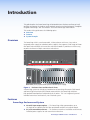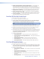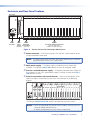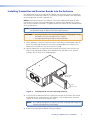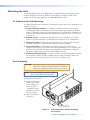
1
User Guide
Fiber Optic Products
PowerCage 1600 Enclosure
™
Modular Power Enclosure for Fiber Optic and Twisted Pair Extenders
68-1717-01 Rev. C
02 12
Safety Instructions • English
Warning
This symbol is intended to alert the user of important operating and maintenance (servicing) instructions in the literature provided with the equipment.
Power sources • This equipment should be operated only from the power source indicated on the product. This
equipment is intended to be used with a main power system with a grounded (neutral) conductor. The third
(grounding) pin is a safety feature, do not attempt to bypass or disable it.
This symbol is intended to alert the user of the presence of uninsulated
dangerous voltage within the product’s enclosure that may present a risk of
electric shock.
Power disconnection • To remove power from the equipment safely, remove all power cords from the rear of
the equipment, or the desktop power module (if detachable), or from the power source receptacle (wall plug).
Caution
Read Instructions • Read and understand all safety and operating instructions before using the equipment.
Retain Instructions • The safety instructions should be kept for future reference.
Follow Warnings • Follow all warnings and instructions marked on the equipment or in the user information.
Avoid Attachments • Do not use tools or attachments that are not recommended by the equipment
manufacturer because they may be hazardous.
Consignes de Sécurité • Français
Ce symbole sert à avertir l’utilisateur que la documentation fournie avec le
matériel contient des instructions importantes concernant l’exploitation et la
maintenance (réparation).
Ce symbole sert à avertir l’utilisateur de la présence dans le boîtier
de l’appareil de  tensions dangereuses non isolées posant des risques
d’électrocution.
Attention
Lire les instructions• Prendre connaissance de toutes les consignes de sécurité et d’exploitation avant
d’utiliser le matériel.
Conserver les instructions• Ranger les consignes de sécurité afin de pouvoir les consulter à l’avenir.
Respecter les avertissements • Observer tous les avertissements et consignes marqués sur le matériel ou
présentés dans la documentation utilisateur.
Eviter les pièces de fixation • Ne pas utiliser de pièces de fixation ni d’outils non recommandés par le
fabricant du matériel car cela risquerait de poser certains dangers.
Sicherheitsanleitungen • Deutsch
Power cord protection • Power cords should be routed so that they are not likely to be stepped on or pinched
by items placed upon or against them.
Servicing • Refer all servicing to qualified service personnel. There are no user-serviceable parts inside. To prevent
the risk of shock, do not attempt to service this equipment yourself because opening or removing covers may
expose you to dangerous voltage or other hazards.
Slots and openings • If the equipment has slots or holes in the enclosure, these are provided to prevent
overheating of sensitive components inside. These openings must never be blocked by other objects.
Lithium battery • There is a danger of explosion if battery is incorrectly replaced. Replace it only with the
same or equivalent type recommended by the manufacturer. Dispose of used batteries according to the
manufacturer’s instructions.
Avertissement
Alimentations • Ne faire fonctionner ce matériel qu’avec la source d’alimentation indiquée sur l’appareil. Ce
matériel doit être utilisé avec une alimentation principale comportant un fil de terre (neutre). Le troisième
contact (de mise à la terre) constitue un dispositif de sécurité : n’essayez pas de la contourner ni de la
désactiver.
Déconnexion de l’alimentation• Pour mettre le matériel hors tension sans danger, déconnectez tous les
cordons d’alimentation de l’arrière de l’appareil ou du module d’alimentation de bureau (s’il est amovible) ou
encore de la prise secteur.
Protection du cordon d’alimentation • Acheminer les cordons d’alimentation de manière à ce que personne
ne risque de marcher dessus et à ce qu’ils ne soient pas écrasés ou pincés par des objets.
Réparation-maintenance • Faire exécuter toutes les interventions de réparation-maintenance par un
technicien qualifié. Aucun des éléments internes ne peut être réparé par l’utilisateur. Afin d’éviter tout danger
d’électrocution, l’utilisateur ne doit pas essayer de procéder lui-même à ces opérations car l’ouverture ou le
retrait des couvercles risquent de l’exposer à de hautes tensions et autres dangers.
Fentes et orifices • Si le boîtier de l’appareil comporte des fentes ou des orifices, ceux-ci servent à empêcher les
composants internes sensibles de surchauffer. Ces ouvertures ne doivent jamais être bloquées par des objets.
Lithium Batterie • Il a danger d’explosion s’ll y a remplacment incorrect de la batterie. Remplacer uniquement
avec une batterie du meme type ou d’un ype equivalent recommande par le constructeur. Mettre au reut les
batteries usagees conformement aux instructions du fabricant.
Vorsicht
Dieses Symbol soll dem Benutzer in der im Lieferumfang enthaltenen
Dokumentation besonders wichtige Hinweise zur Bedienung und Wartung
(Instandhaltung) geben.
Stromquellen • Dieses Gerät sollte nur über die auf dem Produkt angegebene Stromquelle betrieben werden.
Dieses Gerät wurde für eine Verwendung mit einer Hauptstromleitung mit einem geerdeten (neutralen) Leiter
konzipiert. Der dritte Kontakt ist für einen Erdanschluß, und stellt eine Sicherheitsfunktion dar. Diese sollte nicht
umgangen oder außer Betrieb gesetzt werden.
Dieses Symbol soll den Benutzer darauf aufmerksam machen, daß im Inneren
des Gehäuses dieses Produktes gefährliche Spannungen, die nicht isoliert sind
und die einen elektrischen Schock verursachen können, herrschen.
Stromunterbrechung • Um das Gerät auf sichere Weise vom Netz zu trennen, sollten Sie alle Netzkabel aus der
Rückseite des Gerätes, aus der externen Stomversorgung (falls dies möglich ist) oder aus der Wandsteckdose
ziehen.
Achtung
Lesen der Anleitungen • Bevor Sie das Gerät zum ersten Mal verwenden, sollten Sie alle Sicherheits-und
Bedienungsanleitungen genau durchlesen und verstehen.
Aufbewahren der Anleitungen • Die Hinweise zur elektrischen Sicherheit des Produktes sollten Sie
aufbewahren, damit Sie im Bedarfsfall darauf zurückgreifen können.
Befolgen der Warnhinweise • Befolgen Sie alle Warnhinweise und Anleitungen auf dem Gerät oder in der
Benutzerdokumentation.
Keine Zusatzgeräte • Verwenden Sie keine Werkzeuge oder Zusatzgeräte, die nicht ausdrücklich vom
Hersteller empfohlen wurden, da diese eine Gefahrenquelle darstellen können.
Instrucciones de seguridad • Español
Este símbolo se utiliza para advertir al usuario sobre instrucciones importantes de operación y mantenimiento (o cambio de partes) que se desean
destacar en el contenido de la documentación suministrada con los equipos.
Este símbolo se utiliza para advertir al usuario sobre la presencia de elementos con voltaje peligroso sin protección aislante, que puedan encontrarse
dentro de la caja o alojamiento del producto, y que puedan representar
riesgo de electrocución.
Precaucion
Leer las instrucciones • Leer y analizar todas las instrucciones de operación y seguridad, antes de usar el
equipo.
Conservar las instrucciones • Conservar las instrucciones de seguridad para futura consulta.
Obedecer las advertencias • Todas las advertencias e instrucciones marcadas en el equipo o en la
documentación del usuario, deben ser obedecidas.
Evitar el uso de accesorios • No usar herramientas o accesorios que no sean especificamente
recomendados por el fabricante, ya que podrian implicar riesgos.
安全须知 • 中文
这个符号提示用户该设备用户手册中有重要的操作和维护说明。
这个符号警告用户该设备机壳内有暴露的危险电压,有触电危险。
注意
阅读说明书 • 用户使用该设备前必须阅读并理解所有安全和使用说明。
保存说明书 • 用 户应保存安全说明书以备将来使用。
遵守警告 • 用户应遵守产品和用户指南上的所有安全和操作说明。
避免追加 • 不要使用该产品厂商没有推荐的工具或追加设备,以避免危险。
Schutz des Netzkabels • Netzkabel sollten stets so verlegt werden, daß sie nicht im Weg liegen und niemand
darauf treten kann oder Objekte darauf- oder unmittelbar dagegengestellt werden können.
Wartung • Alle Wartungsmaßnahmen sollten nur von qualifiziertem Servicepersonal durchgeführt werden.
Die internen Komponenten des Gerätes sind wartungsfrei. Zur Vermeidung eines elektrischen Schocks
versuchen Sie in keinem Fall, dieses Gerät selbst öffnen, da beim Entfernen der Abdeckungen die Gefahr eines
elektrischen Schlags und/oder andere Gefahren bestehen.
Schlitze und Öffnungen • Wenn das Gerät Schlitze oder Löcher im Gehäuse aufweist, dienen diese zur
Vermeidung einer Überhitzung der empfindlichen Teile im Inneren. Diese Öffnungen dürfen niemals von
anderen Objekten blockiert werden.
Litium-Batterie • Explosionsgefahr, falls die Batterie nicht richtig ersetzt wird. Ersetzen Sie verbrauchte Batterien
nur durch den gleichen oder einen vergleichbaren Batterietyp, der auch vom Hersteller empfohlen wird.
Entsorgen Sie verbrauchte Batterien bitte gemäß den Herstelleranweisungen.
Advertencia
Alimentación eléctrica • Este equipo debe conectarse únicamente a la fuente/tipo de alimentación eléctrica
indicada en el mismo. La alimentación eléctrica de este equipo debe provenir de un sistema de distribución
general con conductor neutro a tierra. La tercera pata (puesta a tierra) es una medida de seguridad, no
puentearia ni eliminaria.
Desconexión de alimentación eléctrica • Para desconectar con seguridad la acometida de alimentación
eléctrica al equipo, desenchufar todos los cables de alimentación en el panel trasero del equipo, o desenchufar
el módulo de alimentación (si fuera independiente), o desenchufar el cable del receptáculo de la pared.
Protección del cables de alimentación • Los cables de alimentación eléctrica se deben instalar en lugares
donde no sean pisados ni apretados por objetos que se puedan apoyar sobre ellos.
Reparaciones/mantenimiento • Solicitar siempre los servicios técnicos de personal calificado. En el interior no
hay partes a las que el usuario deba acceder. Para evitar riesgo de electrocución, no intentar personalmente la
reparación/mantenimiento de este equipo, ya que al abrir o extraer las tapas puede quedar expuesto a voltajes
peligrosos u otros riesgos.
Ranuras y aberturas • Si el equipo posee ranuras o orificios en su caja/alojamiento, es para evitar el
sobrecalientamiento de componentes internos sensibles. Estas aberturas nunca se deben obstruir con otros
objetos.
Batería de litio • Existe riesgo de explosión si esta batería se coloca en la posición incorrecta. Cambiar esta
batería únicamente con el mismo tipo (o su equivalente) recomendado por el fabricante. Desachar las baterías
usadas siguiendo las instrucciones del fabricante.
警告
电源 • 该设备只能使用产品上标明的电源。 设备必须使用有地线的供电系统供电。 第三条线
(地线)是安全设施,不能不用或跳过 。
拔掉电源 • 为安全地从设备拔掉电源,请拔掉所有设备后或桌面电源的电源线,或任何接到市
电系统的电源线。
电源线保护 • 妥善布线, 避免被踩踏,或重物挤压。
维护 • 所有维修必须由认证的维修人员进行。 设备内部没有用户可以更换的零件。为避免出现
触电危险不要自己试图打开设备盖子维修该设备。
通风孔 • 有些设备机壳上有通风槽或孔,它们是用来防止机内敏感元件过热。 不要用任何东
西挡住通风孔。
锂电池 • 不正确的更换电池会有爆炸的危险。必须使用与厂家推荐的相同或相近型号的电池。
按照生产厂的建议处理废弃电池。
ii
FCC Class A Notice
This equipment has been tested and found to comply with the limits for a Class A digital device, pursuant to part 15
of the FCC Rules. Operation is subject to the following two conditions:
1. This device may not cause harmful interference.
2. This device must accept any interference received, including interference that may cause undesired operation.
The Class A limits are designed to provide reasonable protection against harmful interference when the equipment
is operated in a commercial environment. This equipment generates, uses, and can radiate radio frequency energy
and, if not installed and used in accordance with the instruction manual, may cause harmful interference to radio
communications. Operation of this equipment in a residential area is likely to cause harmful interference, in which
case the user will be required to correct the interference at his own expense.
NOTE: This unit was tested with shielded cables on the peripheral devices. Shielded cables must be used with
the unit to ensure compliance with FCC emissions limits.
For more information on safety guidelines, regulatory compliances, EMI/EMF compliance, accessibility, and
related topics, click here.
iii
Conventions Used in this Guide
In this user guide, the following are used:
CAUTION: A caution indicates a potential hazard to equipment or data.
NOTE: A note draws attention to important information.
TIP: A tip provides a suggestion to make working with the application easier.
WARNING: A warning warns of things or actions that might cause injury, death, or
other severe consequences.
Copyright
© 2012 Extron Electronics. All rights reserved.
Trademarks
All trademarks mentioned in this guide are the properties of their respective owners.
iv
Contents
Introduction............................................................ 1
Operation................................................................. 9
Overview............................................................. 1
Features............................................................... 1
PowerCage Enclosure and System.................... 1
PowerCage FOX Fiber Optic Extender Boards... 2
PowerCage MTP Twisted Pair Boards................ 2
System Example................................................... 3
Front Panel Features............................................. 9
Communicating with the Boards: Making an
RS‑232 Connection........................................... 11
Installation.............................................................. 4
Enclosure and Rear Panel Features....................... 5
Installing Transmitter and Receiver Boards into the
Enclosure............................................................ 6
Mounting the Unit............................................... 7
UL Guidelines for Rack Mounting..................... 7
Rack Mounting................................................ 7
Cabling and Testing............................................. 8
Specifications and Part Numbers..................... 12
Specifications..................................................... 12
Part Numbers..................................................... 22
Included Parts................................................ 22
Optional Accessories...................................... 22
Index....................................................................... 24
PowerCage 1600 Enclosure • Contents
v
PowerCage 1600 Enclosure • Contents
vi
Introduction
This guide describes the Extron PowerCage 1600 Modular Power Enclosure and how to install,
configure, and operate the enclosure and its optional transmitter and receiver boards. Throughout
this guide “PowerCage” and “the enclosure” refer to the PowerCage 1600 Enclosure.
This section of the guide covers the following topics:
zz Overview
zz Features
zz System Example
Overview
The PowerCage 1600 is a rack-mountable, 16-slot enclosure with vents, fans, and an
integrated power supply (or redundant power supplies) that supports a wide range of Extron
fiber optic and twisted pair AV transmitter and receiver boards. It provides an efficient way
to power and mount multiple transmitters and receivers.
1
2
3
4
5
6
7
8
9
10
11
12
13
14
15
COMM
POWER
ALARM
16
PSU
1
PSU
2
FAN
1
FAN
2
COMM
SELECT
TEMP
CONFIG
PowerCage 1600
Front Panel (shown with rack ears installed)
PowerCage 1600
Power Supply
PowerCage 1600
Power Supply
N15778
I.T.E.
1T23
100-240V
50/60Hz
5A MAX.
Rear Panel (shown populated with optional redundant power supply)
Figure 1. Enclosure Front and Rear Panel Views
A PowerCage system can include any combination of PowerCage fiber optic (FOX) boards
and PowerCage twisted pair (MTP) boards mounted within the PowerCage enclosure.
Each optional board operates independently of the others. This is an integrated system of
individual transmitters and receivers, not a matrixed system.
Features
PowerCage Enclosure and System
zz Versatile input-output options — The PowerCage 1600 accommodates up to
16 single-slot or 8 double-slot FOX fiber optic boards and MTP twisted pair boards.
zz 3U, rack-mountable enclosure — The enclosure streamlines installation and eliminates
individual power supplies for each transmitter and receiver.
PowerCage 1600 Enclosure • Introduction
1
zz Modular, field-upgradeable, and hot-swappable design — The transmitter and
receiver boards, and primary and redundant power supplies, are hot-swappable,
allowing components to be added or replaced at any time without powering down the
system. This is useful for mission-critical applications that require continuous operation.
zz Efficient power management — Each PowerCage board can power down internal
components when no active signal is present, providing increased system efficiency.
zz Optional redundant power supply — For continuous, mission-critical applications
where power reliability is crucial, add a redundant power supply, part number 70-784-01.
zz Thermal management — The PowerCage enclosure provides channeled air flow to
each board for optimal cooling and reliable operation.
PowerCage FOX Fiber Optic Extender Boards
The fiber optic transmitter and receiver boards:
zz Are available in singlemode or multimode versions.
zz Support standard definition or high resolution video, HDMI, stereo audio, and RS-232
over a single fiber. They extend high resolution RGB, DVI-D, multi-rate SDI, standard
resolution component, S-video, or composite video extreme distances.
NOTE: Two fibers are needed when transmitting an HDCP signal.
zz Deliver pixel-for-pixel image quality for high resolution video. All digital, zero
compression transmission ensures image quality over long distances at high resolutions.
zz Provide alarm notification for fiber link loss and can be set up to trigger an external
control system for immediate notification when a fiber link has been lost.
zz PowerCage FOX DVI, DVI Plus, and VGA Fiber Optic Extenders are compatible with and
can be mixed and matched with FOXBOX and FOX 500 Series transmitters and receivers
for versatile system designs and configurations, including ultra-long distance DVI-toanalog RGB and RGB-to-DVI conversion.
zz Include the following models:
zz
PowerCage FOX VGA — Fiber Optic Extender for VGA, Audio, and RS-232
zz
PowerCage FOX DVI, PowerCage FOX DVI Plus — Fiber Optic Extender for DVI,
Audio, and RS-232
zz
PowerCage FOX 3G HD-SDI — Fiber Optic Extender for Multi-Rate SDI
zz
PowerCage FOX AV — Fiber Optic Extender for Video, Audio, and RS-232
zz
PowerCage FOX HDMI — Fiber Optic Extender for HDMI, Audio, and RS-232
PowerCage MTP Twisted Pair Boards
The twisted pair transmitter and receiver boards:
zz Support standard definition or high resolution video, and audio or RS-232 over a single
CAT 5/5e/6 (shielded or unshielded) cable. They transmit and receive high resolution RGBHV,
RGBS, RGsB, RsGsBs, component video, S-video, and composite video long distances.
zz Include the following models:
zz
PowerCage MTP T 15HD RSA — MTP Twisted Pair Transmitter for VGA and Audio
or RS-232
zz
PowerCage MTP R 15HD RSA SEQ — MTP Twisted Pair Receiver for VGA and
Audio or RS-232 with Skew Equalization
zz
PowerCage MTP T AV — MTP Twisted Pair Transmitter for Composite or S-video
and Audio
zz
PowerCage MTP R AV — MTP Twisted Pair Receiver for Composite or S-video and Audio
PowerCage 1600 Enclosure • Introduction
2
System Example
The following diagram shows a typical PowerCage 1600 system installation.
Building 1
MVX 168 VGA A
INPUTS
1
2
3
4
5
6
7
8
9
Rackmount PCs
10
11
12
13
14
15
MTP R 15HD RSA D
16
CONTROL
Receivers
I/O
CONFIG
1
2
3
4
5
6
7
8
9
10
11
12
13
14
15
16
ENTER
PRESET
VIEW
ESC
VIDEO
AUDIO
OUTPUTS
MVX SERIES
Satellite Receivers
Flat Panel Displays
VGA MATRIX SWITCHER WITH ADPS™
LEVEL
PEAKING
AUDIO RS-232
Tx Rx
OUTPUT
Extron
PowerCage 1600
PEAKING
LEVEL
AUDIO RS-232
PowerCage
FOX 4G Rx VGA
PowerCage
FOX 4G Rx VGA
PowerCage
MTP T
15HD RSA
PowerCage
MTP T
15HD RSA
Tx Rx
OUTPUT
OUTPUT
OUTPUT
OFF
OFF
PRE-PEAK
ON
OFF
OFF
PRE-PEAK
ON
PRE-PEAK
ON
Tx Rx
1 2
OUTPUT
OUTPUT
Rx
PowerCage
MTP T
15HD RSA
INPUT
R
L
MTP 1500RL 15HD A
Tx Rx
Receivers
PEAKING
RGB
MONO
L
MTP
MTP
INPUT
BUFFERED OUTPUT
MTP
MTP
MTP 1500RL Series
OUTPUT
AUDIO
R
ON
MTP 1500RL 15HD A
LEVEL
PEAKING
RGB
MIN/MAX
MTP 1500RL Series
OUTPUT
POWER
12V
1.0A MAX
Building 2
MIN/MAX
H+
V+
CSYNC
SOG
VIDEO
END
SPARE
LEVEL
BUFFERED OUTPUT
INPUT
POWER
12V
1.0A MAX
H+
V+
CSYNC
SOG
VIDEO
END
SPARE
INPUT
RS-232
Tx Rx
L
R
AUDIO INPUT
INPUT
L
R
AUDIO INPUT
RS-232
Tx Rx
OUTPUT
RGB
RS-232
AUDIO INPUT
L
INPUT
AUDIO
R
Tx Rx
REMOTE
RS-232 ALARM
1 2
Tx
Rx
Tx Rx
REMOTE
RS-232 ALARM
Tx Rx
RGB
OUTPUT
L
AUDIO
R
RS-232
OVER FIBER
Tx
Rx
1 2
Tx Rx
RS-232
OVER FIBER
Tx
RGB
OUTPUT
I.T.E.
1T23
100-240V
50/60Hz
5A MAX.
RGB
OUTPUT
N15778
L
AUDIO
R
Tx Rx
REMOTE
RS-232 ALARM
1 2
Tx Rx
Tx Rx
REMOTE
RS-232 ALARM
RS-232
OVER FIBER
L
AUDIO
R
RS-232
OVER FIBER
Tx
Rx
PowerCage
MTP T
15HD RSA
PRE-PEAK
ON
PowerCage
FOX 4G Rx VGA
RS-232
PowerCage
FOX 4G Rx VGA
L
R
AUDIO INPUT
PowerCage 1600
Power Supply
Tx Rx
PowerCage 1600
Power Supply
MONO
L
AUDIO
R
ON
MTP 1500RL 15HD A
FOXBOX DVI Plus
Receivers
Flat Panel Displays
FOXBOX 4G Rx DVI Plus
POWER
12V
1.0A MAX
MODE
DVI-D OUTPUT
LINK
Rx
LINK
DVI
OVER
TEMP
FOX 4G Matrix 3200
AUDIO
Tx
CONFIG
OPTICAL
AUDIO
ON
RS-232
OVER FIBER ALARM
1 2
FOXBOX 4G Rx DVI Plus
INPUTS
POWER
12V
1.0A MAX
MODE
DVI-D OUTPUT
Rx
OPTICAL
AUDIO
ON
RS-232
OVER FIBER ALARM
1 2
FOXBOX 4G Rx DVI Plus
1 2 3 4 5 6 7 8 9 10 11 12 13 14 15 16
Tx Rx
1
2
CONTROL
CONFIG
OUTPUTS
2
LINK
CONFIG
FOXBOX 4G Rx DVI Plus
17 18 19 20 21 22 23 24 25 26 27 28 29 30 31 32
1
LINK
DVI
OVER
TEMP
AUDIO
Tx
1 2 3 4 5 6 7 8 9 10 11 12 13 14 15 16
17 18 19 20 21 22 23 24 25 26 27 28 29 30 31 32
Tx Rx
ENTER
PRESET
VIEW
ESC
FOXBOX VGA
PRIMARY
REDUNDANT
POWER SUPPLY
FOX 4G MATRIX 3200
Receivers
FIBER OPTIC DIGITAL MATRIX SWITCHER
FOXBOX 4G Rx VGA
MODE
POWER
12V
1.0A MAX
OPTICAL
RGB OUTPUT
AUDIO
ON
LINK
Rx
LINK
RGB
OVER
TEMP
AUDIO
Tx
CONFIG
RS-232
OVER FIBER ALARM
1 2
FOXBOX 4G Rx VGA
Tx Rx
MODE
ON
RGB OUTPUT
AUDIO
2
LINK
CONFIG
FOXBOX 4G Rx VGA
POWER
12V
1.0A MAX
1
Rx
LINK
RGB
OVER
TEMP
AUDIO
Tx
OPTICAL
RS-232
OVER FIBER ALARM
1 2
VGA
OPTICAL FIBER
UTP/STP
FOXBOX 4G Rx VGA
Tx Rx
1
2
Figure 2. An Example PowerCage 1600 System Installation
PowerCage 1600 Enclosure • Introduction
3
Installation
Topics covered in this section of the guide include the following:
zz Enclosure and Rear Panel Features
zz Installing the Transmitter and Receiver Board into the Enclosure
zz Mounting the Unit
zz Cabling and Testing
The boards and power supplies are hot-swappable and can be installed or replaced at any
time. However, the most convenient way to proceed with initial installation is as follows:
1. Install the optional redundant power supply and transmitter and receiver boards in the
enclosure.
NOTES: • Cover all empty board slots; do not leave them open. Securely fasten the
screws for boards and blank panels.
• Use a tool to fully tighten the screws after initial installation and
subsequent removal and replacement of the boards.
2. Mount the enclosure to an equipment rack.
3. Connect cables to the transmitter and receiver boards and to input and output devices.
4. Connect the power cable to the unit and test the system.
Heed the following safety information when installing or servicing the PowerCage system:
CAUTION: The PowerCage uses double pole/neutral fusing.
Power must be disconnected before servicing internal components.
Do not leave empty board slots open or uncovered while the unit is
powered on.
PowerCage 1600 Enclosure • Installation
4
Enclosure and Rear Panel Features
Rear Panel
PowerCage 1600
Power Supply
N15778
1T23
I.T.E.
100-240V
50/60Hz
5A MAX.
1
Power
Connector
2
3
Main
Slot for
Power
Redundant
Supply Power Supply
(standard)
(optional)
4
Slots for
Transmitter and Receiver Boards
(up to 16 single-slot or
8 double-slot optional boards)
Figure 3. The Rear Panel of the PowerCage 1600 Enclosure
a Power connector — Connect this port to a 110-240 VAC, 50-60 Hz power source
using a standard IEC power cord.
NOTE: The power supplies and transmitter and receiver boards may be installed or
replaced before or after the unit is powered on.
b Main power supply — This power supply is included with every PowerCage
enclosure. The front panel PSU 1 LEDs indicate the status of this power supply.
c Slot for a redundant power supply — An optional redundant power supply can
be installed in this slot. If this second power supply is installed, the front panel PSU 2
LEDs indicate its status.
d Slots for transmitter and receiver boards — Slots are numbered from 16 to 1
from left to right as viewed from the rear of the unit and shown in the following
diagram:
PowerCage 1600
Power Supply
PowerCage 1600
Power Supply
Slot Numbers
Power Power 16 15 14 13 12 11 10
Supply Supply
1
9
8
7
6
5
4
3
2
1
2
N15778
1T23
I.T.E.
100-240V
50/60Hz
5A MAX.
The front panel board status LED numbers correspond to these slot numbers.
NOTES: • Cover all empty board slots; do not leave them open. Securely fasten the
screws for boards and blank panels.
• A double-slot board connects to the lower-numbered slot.
PowerCage 1600 Enclosure • Installation
5
Installing Transmitter and Receiver Boards into the Enclosure
Any combination of up to 16 single-slot or 8 double-slot transmitter or receiver boards can
be installed in the PowerCage enclosure. The quantity and type of boards varies depending
on the configuration for each installation site.
Before installing the boards in the enclosure, refer to the model-specific guide for each
PowerCage transmitter and receiver board you are installing. Some boards have switches
that must be set before installation. The guides describe the features of each board and how
to set up and cable it.
NOTE: The boards are hot-swappable; they can be installed or removed without turning
off or disconnecting the power to the PowerCage enclosure.
CAUTIONS: • Use ESD precautions when installing a board to avoid damaging it. Keep
the board in the anti-static bag until it is needed.
• Use proper grounding techniques during installation.
1. Where applicable, remove as many blank plates or previously installed boards from the
rear of the PowerCage Enclosure as necessary to accommodate the number of new
boards to be installed. Save the screws for use in step 3.
2. Hold the board with the signal connectors towards you and the LED at the top, and
align the top and bottom grooves of the board with the slide posts in the selected
enclosure slot, as shown in the following figure:
ge
rCa
we AV
Po P R
MT
C
Tx
Rx
INPUT
e
ag I
rC -SD
we
Po HD
X 3G
FO
SHARP GAIN
1
2
Y/VID
MODE
HD/SDI INPUT
MONO
AUDIO OUTPUT
Rx
Tx
1 2
Tx Rx
REMOTE
RS-232 ALARM
Tx Rx
RS-232
OVER FIBER
AUDIO
L
R
Align board and
slide into slot.
RGB
OUTPUT
HD/SDI OUTPUTS
e
ag
B
rC
we
Po X RG
FO
e
ag
B
Figure 4.
Tx Rx
Tx
REMOTE
RS-232 ALARM
Tx Rx
RS-232
OVER FIBER
z
AUDIO
L
R
60H
D
TE
LIS
23
1T
.E.
I.T
OUTPUT
50/
0V X.
-24 MA
100 5A
78
RGB
57
1 2
Rx
rC
we
Po X RG
FO
US
C
N1
Screws
(2 per board)
Inserting Boards into the PowerCage Enclosure
3. Carefully slide the board into the slot, aligning the two tabs on the lower front end of
the board with the matching ports in the enclosure. Push the board firmly into place.
Tighten the screws to secure the board in place.
NOTE: Use a tool to fully tighten the screws after initial installation and subsequent
removal and replacement of the boards.
4. Repeat steps 2 and 3 for all boards needing installation.
PowerCage 1600 Enclosure • Installation
6
Mounting the Unit
The PowerCage enclosure can be mounted in a standard equipment rack before or after
installing transmitter and receiver boards. To rack mount the enclosure, follow the UL
guidelines and refer to the diagram in the “Rack Mounting” section.
UL Guidelines for Rack Mounting
The following Underwriters Laboratories (UL) guidelines pertain to the safe installation of the
equipment in a rack.
1. Elevated operating ambient — If installed in a closed or multi-unit rack assembly,
the operating ambient temperature of the rack environment may be greater than room
ambient. Therefore, consider installing the equipment in an environment compatible with
the maximum ambient temperature specified by the manufacturer [Tma = +32 to +122 °F
(0 to +50 °C)].
2. Reduced air flow — Installation of the equipment in a rack should be such that the
amount of air flow required for safe operation of the equipment is not compromised.
3. Mechanical loading — Mounting of the equipment in the rack should be such that a
hazardous condition is not achieved due to uneven mechanical loading.
4. Circuit overloading — Consideration should be given to the connection of the
equipment to the supply circuit and the effect that overloading of the circuits might have
on overcurrent protection and supply wiring. Appropriate consideration of equipment
nameplate ratings should be used when addressing this concern.
5. Reliable earthing (grounding) — Reliable earthing of rack-mounted equipment should
be maintained. Particular attention should be given to supply connections other than
direct connections to the branch circuit (such as the use of power strips).
Rack Mounting
CAUTION: Leave open space of at least 1U on the top, bottom, and
sides of the enclosure to allow adequate air circulation
and prevent overheating. Do not cover the vents or fans.
NOTE: Air flows through the enclosure from right
to left, as viewed from the front panel.
To rack mount the enclosure:
MODE
Tx
1 2
Tx Rx
REMOTE
RS-232 ALARM
AUDIO
L
R
4
VIDEO
1
RGB
VIDEO
1
RGB
2
HD/SDI INPUT
MODE
OUTPUT
2
3
AUDIO
L
R
HD/SDI INPUT
Rx
1 2
Tx Rx
RS-232
OVER FIBER
Tx Rx
Tx
HD/SDI OUTPUTS
REMOTE
RS-232 ALARM
Rx
Tx
Tx Rx
RS-232
OVER FIBER
Rx
Tx
1 2
Tx Rx
REMOTE
RS-232 ALARM
4
AUDIO
L
R
Rx
Tx
1 2
Tx Rx
RS-232
OVER FIBER
Tx Rx
3
AUDIO
L
R
REMOTE
RS-232 ALARM
Rx
1 2
Tx Rx
RS-232
OVER FIBER
Tx Rx
Tx
Tx Rx
REMOTE
RS-232 ALARM
AUDIO
L
R
4
OUTPUT
Rx
Tx
1 2
RS-232
OVER FIBER
REMOTE
RS-232 ALARM
Tx Rx
Tx Rx
60H
VIDEO
1
RGB
OUTPUT
2
3
RS-232
OVER FIBER
AUDIO
L
R
2. Fasten the brackets
to the rack.
HD/SDI OUTPUTS
Rx
Tx
Rx
1. Attach the mounting
brackets to the sides
of the enclosure, as
shown in figure 5.
The brackets can be
attached at either the
front or the back.
z
50/
0V X.
-24 MA
100 5A
3-U Rack Mount Bracket
(use four mounting holes)
Figure 5.
Attaching Brackets and Rack Mounting
the Enclosure
PowerCage 1600 Enclosure • Installation
7
Cabling and Testing
Refer to the setup guides and user guides for the models of transmitter and receiver boards
you are installing for details on how to cable and set up each board.
zz Some fiber optic boards include pass-through RS-232 connections.
zz Some boards have mode switches.
zz Some MTP twisted pair boards include picture adjustment or peaking controls.
PowerCage 1600 Enclosure • Installation
8
Operation
The following topics are covered in this section of the guide:
zz Front Panel Features
zz Communicating with the Boards: Making an RS‑232 Connection
Front Panel Features
The front panel of the PowerCage 1600 Enclosure provides a variety of light emitting diode
(LED) status indicators, a selection button, and a port for communicating with an active
installed board. See the diagram below and the following descriptions for details.
Front Panel
1
2
3
4
5
6
7
8
9
10
11
12
13
14
15
16
PSU
1
COMM
POWER
ALARM
PSU
2
FAN
1
FAN
2
COMM
SELECT
TEMP
CONFIG
PowerCage 1600
1
2
Board Status LEDs
(for multi-function boards,
up to 16 optional boards)
3
4
5
6
Power Supply Fan
Communication Configuration System
Status LEDs Status Selection
Port (RS-232) Temperature
LEDs Button
Status LED
Figure 6. The PowerCage 1600 Enclosure Front Panel
a Board status LEDs (Comm, Power, Alarm) — There is one set of these LEDs for
each of the 16 rear panel slots that is available for boards. If a board is installed in the
identically-numbered slot, the LEDs light under the following circumstances:
1
COMM
POWER
ALARM
d
, Comm Select
Comm LED — Lights when the corresponding board is selected (see
button) and, for FOX boards, can be communicated with via the Config port ( ).
Power LED — Lights when the corresponding board receives power.
e
Alarm LED — Lights when the receiving (Rx) fiber link on a PowerCage FOX board is
broken or disconnected. This feature depends on the model of PowerCage board.
This LED is not used for PowerCage MTP boards.
NOTE: For a double-slot board, the status LEDs light only for the lower-numbered slot.
b Power supply (PSU) status LEDs — These pairs of LEDs correspond to the primary
(included) power supply and the redundant (optional) power supply. For each power
supply, the LEDs light as follows:
PSU
1
PSU
2
Power LED — Lights when the power supply receives power.
Alarm LED — Lights when the power supply malfunctions, such as providing an
overvoltage (14 VDC or more) or undervoltage (10.5 VDC or less).
PowerCage 1600 Enclosure • Operation
9
c Fan status LEDs — These LEDs indicate whether the fans that cool the enclosure are
operating.
FAN
1
FAN
2
Power LED — Lights when the corresponding fan receives power.
Alarm LED — Lights when the corresponding fan malfunctions.
d Communication selection (Comm Select) button — Press this button to select
the desired board to connect to the Config port (e). With each button press, the
serial connection changes from one active, installed board to the next. The Comm LED
(see a) for the selected board lights.
NOTES: • When unit power is cycled (removed then restored), the serial connection
returns to the board in the lowest-numbered slot.
• The Comm LED lights for each installed, powered board as its slot is
selected, regardless of the type of board. However, RS‑232 communication
works only with FOX boards; commands and queries cannot be sent to or
passed through the MTP boards.
e Configuration and communication (Config) port — For RS-232 serial
communication with any installed board, connect a Windows®-based PC or an RS‑232
control system to this 2.5 mm mini stereo-style (tip-ring-sleeve) jack. Use the Extron
9-pin D to 2.5 mm st ereo mini TRS RS-232 cable (part number 70-335-01, shown in the
following figure) or make your own cable.
6 feet
(1.8 m)
1
6
5
9
Part 70-335-01
Tip
Ring
Sleeve (Gnd)
9-pin D
Connection
TRS Plug
Pin 2
Pin 3
Pin 5
Computer's Rx line
Computer's Tx line
Computer's signal ground
Tip
Ring
Sleeve
Figure 7.
9-pin D to 2.5 mm Stereo Mini TRS RS-232 Cable
RS-232 protocol varies depending on the board being communicated with (see the
specifications section), but all boards accept this basic set of protocol:
• 9600 baud
• 1 stop bit
• no parity
• 8 data bits
• no flow control
NOTE: This port allows serial communication to the boards only, not to the
enclosure, itself. The power supply and fan status LEDs provide feedback
about the condition of the enclosure.
f Temperature status (Temp) LED — This LED lights when the unit as a whole
is operating at a dangerously high temperature (approximately 167 °F [75°C]) and
equipment damage is imminent. If the Temp LED lights, power down the unit, ensure
adequate ventilation, and allow the PowerCage system to cool before restoring power.
PowerCage 1600 Enclosure • Operation
10
Communicating with the Boards: Making an RS‑232 Connection
RS‑232 communication works only with FOX boards; commands and queries cannot be
sent to or passed through the MTP boards. To communicate with and check some basic
information about individual installed transmitter or receiver boards, do the following:
1. Connect the serial port of a Windows-based PC or an
RS‑232 control device to the front panel Config port
on the PowerCage system, and power on both devices.
Front Panel
2. Set the serial connection as follows:
• 9600 baud
• 1 stop bit
• no parity
• 8 data bits
• no flow control
COMM
SELECT
TEMP
3. Press the Comm Select button to select the desired
board to connect to the Config port. The Comm LED
for the selected board lights. With each button press,
the serial connection changes from one installed board
to the board installed in the next higher-numbered slot,as
shown in the following figure. (The next slot may not be
numbered contiguously with the previously selected board.)
PowerCage
FOX Rx DVI
Rx
PowerCage
FOX 3G HD-SDI
Tx
OUTPUT
INPUT
OFF
HD/SDI OUTPUTS
OUTPUT
Tx Rx
PRE-PEAK
ON
1 2
R
INPUT
9
8
7
6
5
4
MODE
HD/SDI INPUT
R
L
R
G/L
B/P
Tx Rx
RS-232
SELECT
DVI
ADJUST
AUDIO INPUT
AUDIO RS-232
Tx Rx
L
INPUT
DVI
2
VIDEO INPUT
1
R
L
16 15 14 13 12 11 10
Rear Panel
AUDIO
R
L
OUTPUT
4
3
L
AUDIO
R
AUDIO
Y/VID
Y/VID
SHARP GAIN
1
2
MONO
AUDIO OUTPUT
I.T.E.
1T23
AUDIO INPUT
N15778
100-240V
50/60Hz
5A MAX.
PowerCage
MTP T
15HD RSA
Rx
Tx
Tx Rx
RS-232
OVER FIBER
Tx
1 2
Tx Rx
Tx Rx
REMOTE
RS-232 ALARM
RS-232
OVER FIBER
PC or RS-232
Control Device
PowerCage
MTP R
15HD RSA SEQ
REMOTE
RS-232 ALARM
Rx
1 2
Tx Rx
Tx Rx
REMOTE
RS-232 ALARM
RS-232
OVER FIBER
Tx
OUTPUT
INPUT
RS-232
C
C
PowerCage 1600
PowerCage
FOX Tx DVI
Rx
PowerCage
FOX Tx AV
PowerCage
MTP T AV
PowerCage
MTP R AV
CONFIG
3
2
1 Slot Number
Jumps to Populated Board Number
Appropriate LED Lights
1
2
COMM
POWER
ALARM
3
4
5
6
7
8
9
10
11
12
13
14
15
16
PSU
1
PSU
2
FAN
1
FAN
2
COMM
SELECT
TEMP
CONFIG
PowerCage 1600
Front Panel
Figure 8.
Changing Serial Connections From One Board to the Next
NOTES: • The Comm LED lights for each installed, powered board as its slot is
selected, regardless of the type of board. For a double-slot board, only the
LED for the lower-numbered slot lights.
•• The serial connection remains with the last-selected board while the unit is
on. When unit power is cycled (removed then restored), the serial connection returns to the board in the lowest-numbered slot.
4. Use a terminal emulation program such as Telnet or Extron DataViewer to send Simple
Instruction Set (SIS) commands and queries to the selected board. For model-specific
commands and adjustments, refer to the user guide for each model of board that is
installed in the PowerCage Enclosure.
PowerCage 1600 Enclosure • Operation
11
Specifications and
Part Numbers
This section of the guide includes the following material:
zz Specifications
zz Part Numbers (for included parts and accessories)
Specifications
NOTE: The PowerCage FOX boards are available in singlemode or multimode versions.
NOTE: The optional PowerCage FOX boards are class 1 laser products. They meet the safety regulations of
IEC‑60825, FDA 21 CFR 1040.10, and FDA 21 CFR 1040.11.
Optical specifications — PowerCage FOX boards, interconnection between
transmitter and receiver
Number/type���������������������������������� 1 singlemode or 1 multimode fiber optic input and output per FOX board, up to
8 double space boards per PowerCage enclosure
NOTE: Only one fiber is required to transmit video, audio, and unidirectional data. A second fiber is required to
transmit return data for bidirectional control/communication.
Connectors������������������������������������ 2 bidirectional LC connectors per FOX board
Operating distance
Singlemode����������������������������� 30 km (18.75 miles) with singlemode (SM) cables with a SM board
Multimode������������������������������� 300 m (985') with 62.5 µm OM1 multimode (MM) cable and a MM board
1 km (3280') with 50 µm OM2 multimode (MM) cable and a MM board
2 km (6561') with 50 µm OM3/OM4 2000 MHz bandwidth laser optimized MM
cable and a MM board
NOTE: Operating distance is approximate. These are typical distances. The maximum distance may be greater
than these typical numbers depending on factors such as fiber type, fiber bandwidth, connector splicing,
losses, modal or chromatic dispersion, environmental factors, and kinks.
Nominal peak wavelength�������������� 850 nm for multimode (MM), 1310 nm for singlemode (SM)
Transmission power, singlemode or multimode
-5 dBm, typical
Maximum receiver sensitivity
Singlemode����������������������������� -18 dBm, typical
Multimode������������������������������� -12 dBm, typical
Optical loss budget
Singlemode����������������������������� 13 dB, maximum
Multimode������������������������������� 7 dB, maximum
Maximum channel data rate
PowerCage FOX AV boards������ 2.125 Gbps
PowerCage FOX HDMI boards� 4.95 Gbps (1.65 Gbps per color)
Other PowerCage FOX boards� 4.25 Gbps
PowerCage 1600 Enclosure • Specifications and Part Numbers
12
Video — PowerCage FOX Tx/Rx VGA
NOTE: For PowerCage FOX VGA boards, the analog video input signal is digitized pixel for pixel in the transmitter,
sent digitally through the fiber cable, and converted back to analog video in the receiver.
Signal type������������������������������������� VGA-UXGA RGBHV, RGBS, RGsB, RsGsBs
Gain����������������������������������������������� Unity
Pixel data bit depth������������������������ 8 bits per channel, 3 channels (R, G, B)
Maximum resolution���������������������� 1600x1200 or 1080p @ 60 Hz, digitized pixel for pixel; higher resolutions up to
2048x1120, undersampled
Video input — PowerCage FOX Tx VGA
Number/signal type������������������������ 1 VGA-UXGA RGBHV, RGBS, RGsB, RsGsBs
Connector�������������������������������������� 1 female 15-pin HD
Nominal levels�������������������������������� 0.7 Vp-p for RGB
Minimum/maximum levels�������������� Analog: 0.3 V to 0.75 Vp-p with no offset, terminated
Impedance������������������������������������� 75 ohms
Horizontal frequency���������������������� 24 kHz to 100 kHz
Vertical frequency��������������������������� 40 Hz to 120 Hz
Return loss������������������������������������� <-40 dB @ 5 MHz
Video output — PowerCage FOX Rx VGA
Number/signal type������������������������ With input from a FOXBOX Tx VGA or a FOX 500 Tx:
1 VGA-UXGA RGBHV, RGsB (follows input or can be set by user)
With input from a FOXBOX Tx VGA/YUV:
1 VGA-UXGA RGBHV, component video (bi- or tri-level YUV, 480p, 576p, 720p,
1080i, 1080p)
Connector�������������������������������������� 1 female 15-pin HD
Nominal levels�������������������������������� 1 Vp-p for Y of component video
0.7 Vp-p for RGB and for R-Y and B-Y of component video
Minimum/maximum levels�������������� 0.3 V to 0.75 Vp-p, terminated
Impedance������������������������������������� 75 ohms
Return loss������������������������������������� -30 dB @ 5 MHz
DC offset��������������������������������������� ±5 mV with input at 0 offset
Video delay������������������������������������ 1-2 frames
Sync — PowerCage FOX Tx/Rx VGA
Input type�������������������������������������� RGBHV, RGBS, RGsB, RsGsBs
Output type����������������������������������� RGBHV, RGsB (follows input or can be set by user)
Input level�������������������������������������� 2.5 V to 5.0 Vp-p
Output level����������������������������������� TTL: 5.0 Vp-p, unterminated, on HV, for RGBHV, RGBS
0.3 Vp-p for component video (bi-level sync) or for Gs (SOG)
0.6 Vp-p for component video (tri-level sync)
Input impedance���������������������������� 10k ohms
Output impedance������������������������� 75 ohms
Polarity������������������������������������������� Positive or negative (follows input or can be set by user)
Video — PowerCage FOX Tx DVI, PowerCage FOX Tx/Rx DVI Plus
Resolution range
PowerCage FOX Tx DVI������������ Up to 1600x1200 or 1080p @ 60 Hz pixel for pixel; higher resolutions up to
1920x1200 @ 60 Hz, undersampled
PowerCage FOX Tx/Rx DVI Plus Up to 1920x1200 or 1080p @ 60 Hz pixel for pixel
Formats������������������������������������������ RGB and YCbCr digital video
Standards��������������������������������������� DVI 1.0, HDMI
PowerCage 1600 Enclosure • Specifications and Part Numbers
13
Video input — PowerCage FOX Tx DVI, PowerCage FOX Tx DVI Plus
Number/signal type������������������������ 1 single link DVI-D (or HDMI*)
Connector�������������������������������������� 1 female DVI-I
NOTE: *Appropriate DVI-D to HDMI cables or adapters are required for HDMI signal input/output. The PowerCage
FOX DVI and DVI Plus boards can be used to distribute HDMI signals if you use a DVI-to-HDMI adapter.
However, when using HDMI signals, these units do not transmit audio and CEC signals.
These boards do not support transmission of DVI signals with High-bandwidth Digital Content Protection (HDCP).
Video output — PowerCage FOX Rx DVI Plus
Number/signal type������������������������ 1 single link DVI-D (or HDMI*)
Connector�������������������������������������� 1 female DVI-I
Nominal level��������������������������������� 0.8 Vp-p
Video delay������������������������������������ 1-2 frames
Video — PowerCage FOX 3G HD-SDI
NOTE: The PowerCage FOX 3G HD-SDI is a transceiver that can function as a transmitter or as a receiver. Two
units are required for a transmitter-receiver system with one fiber optic cable linking the two units.
Signal type������������������������������������� HD-SDI, SDI, and 3G-SDI digital video signals
Gain����������������������������������������������� Unity
Resolution�������������������������������������� 8 or 10 bits, automatic
Data rates�������������������������������������� 270 Mbps, 1.485 Gbps, 2.970 Gbps
Operation standards����������������������� SMPTE 259M-C, SMPTE 292M, SMPTE 424M, ITU-R BT.601, ITU-R BT.1120
Auto data rate lock������������������������ Yes
Video input — PowerCage FOX 3G HD-SDI transmitter
Number/signal type������������������������ 1 single link SDI, HD-SDI, or 3G-SDI digital component video
Connectors������������������������������������ 1 female BNC
Data rates�������������������������������������� 19 Mbps to 2.97 Gbps
Nominal level��������������������������������� 0.8 Vp-p
Minimum/maximum levels�������������� 0.5 V to 1 Vp-p with no offset
Impedance������������������������������������� 75 ohms
Return loss������������������������������������� ≥15 dB @ 5 MHz to 1.5 GHz
≥10 dB @ 1.5 GHz to 3 GHz
DC offset (max. allowable)������������� 5 V
Input coupling�������������������������������� AC
Input cable equalization����������������� Automatic for up to -30 dB of cable loss
HD-SDI������������������������������������ 120 m (400') using Extron RG6 cable
90 m (300') using Extron RG59 cable
SDI������������������������������������������ 150 m (500') using Extron RG6 cable
120 m (400') using Extron RG59 cable
NOTE: The transmission distance varies depending on the signal resolution and on the type of cable, graphics card,
and display used in the system.
Video output — PowerCage FOX 3G HD-SDI receiver
Number/signal type������������������������ 2 single link SDI, HD-SDI, or 3G-SDI digital component video
Connectors������������������������������������ 2 female BNC
Re-clocking������������������������������������ Automatic for 270 Mbps, 1.485 Gbps, 2.97 Gbps, or bypassed for unrecognized
rates
Nominal level��������������������������������� 0.8 Vp-p
Minimum/maximum levels�������������� 0.5 V to 1.0 Vp-p
Impedance������������������������������������� 75 ohms
Return loss������������������������������������� <-25 dB @ 100 MHz
DC offset��������������������������������������� ±5 mV with input at 0 offset
PowerCage 1600 Enclosure • Specifications and Part Numbers
14
Video — PowerCage FOX Tx/Rx AV
NOTE: For PowerCage FOX AV boards, the analog video input signal is digitized pixel for pixel in the transmitter,
sent digitally through the fiber cable, and converted back to analog video in the receiver.
Gain����������������������������������������������� Unity
Standards
Input��������������������������������������� NTSC 3.58, NTSC 4.43, PAL, SECAM, autodetected
Output������������������������������������ NTSC 3.58, PAL (follows vertical rate)
Decoder type���������������������������������� Adaptive 2D, digital comb filter
Video input — PowerCage FOX Tx AV
Number/signal type������������������������ 1 component (Y, R-Y, B-Y), S-video, composite video
Connectors������������������������������������ 1 x 3 female BNC or 1 female 4-pin mini DIN for S-video
Nominal levels�������������������������������� 1.0 Vp-p for Y of component video and S-video, and for composite video
0.7 Vp-p for R-Y, B-Y of component video
0.3 Vp-p for C of S-video
Minimum/maximum levels�������������� Analog: 0.3 V to 1.5 Vp-p with no offset
Impedance������������������������������������� 75 ohms
Return loss������������������������������������� -30 dB for Y/VID, B-Y/C, R-Y @ 5 MHz
Input coupling�������������������������������� AC
Video output — PowerCage FOX Rx AV
Number/signal type������������������������ 1 component (Y, R-Y, B-Y) video, S-video, composite video
Connectors������������������������������������ 1 x 3 female BNC or 1 female 4-pin mini DIN for S-video
Nominal levels�������������������������������� 1.0 Vp-p for Y of component video and S-video, and for composite video
0.7 Vp-p for R-Y, B-Y of component video
0.3 Vp-p for C of S-video
Minimum/maximum levels�������������� 0.3 V to 1.5 Vp-p
Impedance������������������������������������� 75 ohms
Return loss������������������������������������� <-40 dB @ 5 MHz
DC offset��������������������������������������� +350 mV, maximum, with input at 0 offset
Video delay������������������������������������ 1-2 frames
Video — PowerCage FOX Tx/Rx HDMI
NOTE: Appropriate DMI to DVI-D cables or adapters are required for DVI signal input and output.
Maximum data rate������������������������ 4.95 Gbps (1.65 Gbps per color)
Maximum pixel clock���������������������� 165 MHz
Resolution range���������������������������� Up to 1920x1200 or 1080p @ 60 Hz, 8-bit color
Formats������������������������������������������ RGB, YCbCr, xvYCC digital video
Standards��������������������������������������� DVI 1.0, HDMI, HDCP 1.1, CEA-861E
Video input — PowerCage FOX Tx HDMI
Number/signal type������������������������ 1 single link HDMI
Connectors������������������������������������ 1 female 19-pin HDMI type A
Video output — PowerCage FOX Rx HDMI
Number/signal type������������������������ 1 single link HDMI
Connectors������������������������������������ 1 female 19-pin HDMI type A
Video — PowerCage MTP T 15HD RSA, PowerCage MTP R 15HD RSA SEQ
Gain����������������������������������������������� Unity
Number/signal type������������������������ 1 set of proprietary analog signals
Connector�������������������������������������� 1 female RJ-45
PowerCage 1600 Enclosure • Specifications and Part Numbers
15
Video input — PowerCage MTP T 15HD RSA
Number/signal type������������������������ 1 analog RGBHV, RGBS, RGsB, RsGsBs, component video (YUVi or YUVp/HDTV),
S-video, or composite video
Connector�������������������������������������� 1 female 15-pin HD
Nominal levels�������������������������������� 1 Vp-p for Y of component video and S-video, and for composite video
0.7 Vp-p for RGB and for R-Y and B-Y of component video
0.3 Vp-p for C of S-video
Minimum/maximum levels�������������� 0.3 V to 1.45 Vp-p
Impedance������������������������������������� 75 ohms
Horizontal frequency���������������������� 15 kHz to 130 kHz
Vertical frequency��������������������������� 30 Hz to 150 Hz
Return loss������������������������������������� <-30 dB @ 5 MHz
DC offset (max. allowable)������������� 250 mV
Video output — PowerCage MTP R 15HD RSA SEQ
Number/signal type������������������������ 1 analog VGA-UXGA RGBHV, RGBS, RGsB, RsGsBs, component video (YUVi or
YUVp/HDTV), S-video, or composite video
Connector�������������������������������������� 1 female 15-pin HD
Nominal levels�������������������������������� 1 Vp-p for Y of component video and S-video, and for composite video
0.7 Vp-p for RGB and for R-Y and B-Y of component video
0.3 Vp-p for C of S-video
Minimum/maximum levels�������������� 0.3 V to 1.45 Vp-p
Impedance������������������������������������� 75 ohms
Return loss������������������������������������� <-30 dB @ 5 MHz
DC offset��������������������������������������� <±35 mV with input at 0 offset
Skew compensation����������������������� 62 ns
Maximum resolution���������������������� Up to 1920x1200 or 2048x1080 or 1080p at 300'
Up to 1024x768 at 600'
NOTE: Refer to the user guide for the maximum distances recommended for specific resolutions.
Sync — PowerCage MTP T 15HD RSA, PowerCage MTP R 15HD RSA SEQ
Input/output type��������������������������� RGBHV, RGBS, RGsB, RsGsBs
Standards��������������������������������������� NTSC 3.58, NTSC 4.43, PAL, SECAM
Input level (transmitter)������������������ 3.5 V to 5.5 Vp-p, unterminated
Output level (receiver)�������������������� 4.0 V to 5.0 Vp-p, unterminated
Input impedance (transmitter)�������� 573 ohms ±5%
Output impedance (receiver)���������� 110 ohms
Polarity
Transmitter������������������������������ Positive or negative (follows input polarity)
Receiver����������������������������������� Positive or negative (switch-selectable)
Video — PowerCage MTP T AV, PowerCage MTP R AV
Gain����������������������������������������������� Unity
Differential phase error������������������� <1.0° at 3.58 MHz and 4.43 MHz
Differential gain error��������������������� <1.0% at 3.58 MHz and 4.43 MHz
Video input — PowerCage MTP T AV
Number/signal type������������������������ 1 S-video or composite video
Connectors������������������������������������ 2 female BNC
Nominal level��������������������������������� 1 Vp-p for Y of S-video and for composite video
0.3 Vp-p for C of S-video
Minimum/maximum levels�������������� 0.3 V to 1.5 Vp-p with no offset
Impedance������������������������������������� 75 ohms
Return loss������������������������������������� <-30 dB, DC @ 10 MHz
DC offset (max. allowable)������������� 250 mV
PowerCage 1600 Enclosure • Specifications and Part Numbers
16
Video output — PowerCage MTP R AV
Number/signal type������������������������ 1 S-video or composite video
Connectors������������������������������������ 2 female BNC
Nominal level��������������������������������� 1 V p-p for Y of S-video and for composite video
0.3 V p-p for C of S-video
Minimum/maximum level��������������� 0.3 V to 1.5 Vp-p
Impedance������������������������������������� 75 ohms
Return loss������������������������������������� <-35 dB @ 5 MHz
DC offset��������������������������������������� ±20 mV with input at 0 offset
Sync — PowerCage MTP T AV, PowerCage MTP R AV
Standards��������������������������������������� NTSC 3.58, NTSC 4.43, PAL, SECAM
Audio — PowerCage FOX Tx/Rx VGA, PowerCage FOX Tx DVI,
PowerCage FOX Tx/Rx DVI Plus, PowerCage FOX Tx/Rx AV, PowerCage FOX Tx/Rx HDMI
NOTE: In PowerCage FOX boards, the analog audio signal(s) is (are) digitized in the transmitter, sent through the
fiber cable, and converted back to analog audio in the receiver.
Gain
Range�������������������������������������� Adjustable, -18 dB to +10 dB
Default
PowerCage FOX Tx/Rx HDMI Unbalanced output: 0 dB
All other boards����������������� Unbalanced output: -6 dB; balanced output: 0 dB
Frequency response������������������������ 20 Hz to 20 kHz, ±0.5 dB
THD + Noise
VGA, DVI, and HDMI boards���� 0.10% @ 1 kHz at nominal level
AV boards�������������������������������� 0.15% @ 1 kHz at nominal level
S/N������������������������������������������������� >80 dB at maximum output (unweighted)
CMRR�������������������������������������������� 65 dB @ 20 Hz to 20 kHz
Audio bits per sample��������������������� 18 bits per channel, 2 channels (L, R)
Sampling rate��������������������������������� 48 kHz
Audio input — PowerCage FOX Tx VGA, PowerCage FOX Tx DVI,
PowerCage FOX Tx DVI Plus
Number/signal type������������������������ 1 stereo, balanced/unbalanced or
2 mono, balanced/unbalanced
Connector�������������������������������������� (1) 3.5 mm captive screw connector, 5 pole
Impedance������������������������������������� 18k ohms unbalanced, DC coupled
Nominal level��������������������������������� +4 dBu (1.23 Vrms), -10 dBV (316 mVrms)
Maximum level������������������������������� +8.9 dBV, unbalanced at 1% THD+N
NOTE: 0 dBu = 0.775 Vrms, 0 dBV = 1 Vrms, 0 dBV ≈ 2 dBu
Audio input — PowerCage FOX Tx AV
Number/signal type������������������������ 1 stereo, balanced/unbalanced or
2 mono, balanced/unbalanced
Connector�������������������������������������� (1) 3.5 mm captive screw connector, 5 pole
Impedance������������������������������������� >10k ohms unbalanced, >20k ohms balanced, DC coupled
Nominal levels�������������������������������� +4 dBu (1.23 Vrms), -10 dBV (316 mVrms)
Maximum level������������������������������� +17 dBV, unbalanced at 1% THD+N
NOTE: 0 dBu = 0.775 Vrms, 0 dBV = 1 Vrms, 0 dBV ≈ 2 dBu
PowerCage 1600 Enclosure • Specifications and Part Numbers
17
Audio input — PowerCage FOX Tx HDMI
Number/signal type������������������������ 1 unbalanced stereo or 2 unbalanced mono
Connectors������������������������������������ (1) 3.5 mm mini stereo jack
Impedance������������������������������������� 18k ohms unbalanced, DC coupled
Nominal level��������������������������������� +4 dBu (1.23 Vrms), -10 dBV (316 mVrms)
Maximum level������������������������������� +8.9 dBV, unbalanced at 1% THD+N
NOTE: 0 dBu = 0.775 Vrms, 0 dBV = 1 Vrms, 0 dBV ≈ 2 dBu
Audio output — PowerCage FOX Rx VGA, PowerCage FOX Rx DVI Plus
Number/signal type������������������������ 1 stereo, balanced/unbalanced or
2 mono, balanced/unbalanced
Connector�������������������������������������� (1) 3.5 mm captive screw connector, 5 pole
Impedance������������������������������������� 50 ohms unbalanced, 100 ohms balanced
Nominal level��������������������������������� +4 dBu (1.23 Vrms), -10 dBV (316 mVrms)
Maximum level (Hi-Z)���������������������� +7.6 dBu, unbalanced at 1% THD+N
Maximum level (600 ohms)������������ >+6.3 dBu, unbalanced at 1% THD+N
Audio delay������������������������������������ 1.5 frames
Audio output — PowerCage FOX Rx AV
Number/signal type������������������������ 1 stereo, balanced/unbalanced or
2 mono, balanced/unbalanced
Connector�������������������������������������� (1) 3.5 mm captive screw connector, 5 pole
Impedance������������������������������������� 50 ohms unbalanced, 100 ohms balanced
Nominal levels�������������������������������� +4 dBu (1.23 Vrms), -10 dBV (316 mVrms)
Maximum level (Hi-Z)���������������������� >+19 dBu, unbalanced at 1% THD+N
Maximum level (600 ohm)�������������� >+15 dBm, unbalanced at 1% THD+N
Audio delay������������������������������������ 1.5 frames
Audio output — PowerCage FOX Rx HDMI
Number/signal type������������������������ 1 balanced/unbalanced stereo or 2 balanced/unbalanced mono
Connectors������������������������������������ (1) 3.5 mm captive screw connector, 5 pole
Impedance������������������������������������� 50 ohms unbalanced
Nominal level��������������������������������� +4 dBu (1.23 Vrms), -10 dBV (316 mVrms)
Maximum level (Hi-Z)���������������������� >+11.0 dBu, balanced at 1% THD+N
Maximum level (600 ohm)�������������� >+10.0 dBu, balanced at 1% THD+N
Audio delay������������������������������������ 1.5 frames
Audio — PowerCage MTP T 15HD RSA, PowerCage MTP R 15HD RSA SEQ
Number/signal type������������������������ 1 set of proprietary analog signals
Connector�������������������������������������� 1 female RJ-45
Gain����������������������������������������������� Unbalanced output: 0 dB; balanced output: +6 dB
Frequency response������������������������ 20 Hz to 20 kHz, ±1 dB
THD + Noise����������������������������������� 0.15% @ 1 kHz, 0.3% @ 20 kHz at nominal level
S/N������������������������������������������������� >70 dB at maximum output (unweighted)
Stereo channel separation�������������� >60 dB @ 1 kHz
CMRR�������������������������������������������� >43 dB @ 20 Hz to 20 kHz
Audio input — PowerCage MTP T 15HD RSA
Number/signal type������������������������ 1 stereo, unbalanced
Connector�������������������������������������� (1) 3.5 mm captive screw connector, 5 pole
Impedance������������������������������������� >10k ohms, unbalanced
Nominal levels�������������������������������� +4 dBu (1.23 Vrms), -10 dBV (316 mVrms)
Maximum level������������������������������� +18 dBu, (unbalanced) at 1% THD+N
NOTE: 0 dBu = 0.775 Vrms, 0 dBV = 1 Vrms, 0 dBV ≈ 2 dBu
PowerCage 1600 Enclosure • Specifications and Part Numbers
18
Audio output — PowerCage MTP R 15HD RSA SEQ
Number/signal type������������������������ 1 mono, balanced/unbalanced
Connector�������������������������������������� (1) 3.5 mm captive screw connector, 5 pole
Impedance������������������������������������� 50 ohms unbalanced, 100 ohms balanced
Gain error�������������������������������������� ±1 dB channel to channel
Nominal levels�������������������������������� +4 dBu (1.23 Vrms), -10 dBV (316 mVrms)
Maximum level������������������������������� +18 dBu, unbalanced at 1% THD+N
Audio — PowerCage MTP T AV, PowerCage MTP R AV
Number/signal type������������������������ 1 set of proprietary analog signals
Connector�������������������������������������� 1 female RJ-45
Gain����������������������������������������������� Unbalanced output: 0 dB; balanced output: +6 dB
Frequency response������������������������ 20 Hz to 20 kHz, ±1 dB
THD + Noise����������������������������������� 0.15% @ 1 kHz, 0.3% @ 20 kHz at nominal level
S/N������������������������������������������������� >70 dB at maximum output (unweighted)
Crosstalk���������������������������������������� <-80 dB @ 1 kHz, fully loaded
Stereo channel separation�������������� >60 dB @ 1 kHz
CMRR�������������������������������������������� >43 dB @ 20 Hz to 20 kHz
Audio input — PowerCage MTP T AV
Number/signal type������������������������ 1 stereo, balanced/unbalanced
Connector�������������������������������������� (1) 3.5 mm captive screw connector, 5 pole
Impedance������������������������������������� >10k ohms, unbalanced; >20k ohms, balanced; AC coupled
Nominal levels�������������������������������� +4 dBu (1.23 Vrms), -10 dBV (316 mVrms)
Maximum level������������������������������� +18 dBu, (unbalanced) at 1% THD+N
NOTE: 0 dBu = 0.775 Vrms, 0 dBV = 1 Vrms, 0 dBV ≈ 2 dBu
Audio output — PowerCage MTP R AV
Number/signal type������������������������ 2 mono, balanced/unbalanced
Connector�������������������������������������� (1) 3.5 mm captive screw connector, 5 pole
Impedance������������������������������������� 50 ohms unbalanced, 100 ohms balanced
Gain error�������������������������������������� ±1 dB channel to channel
Nominal levels�������������������������������� +4 dBu (1.23 Vrms), -10 dBV (316 mVrms)
Maximum level������������������������������� +18 dBu, unbalanced at 1% THD+N
PowerCage 1600 Enclosure • Specifications and Part Numbers
19
Control/remote
NOTE: PowerCage MTP AV Series boards do not have any RS-232 communication.
PowerCage MTP 15HD Series boards have only pass-through RS-232 communication.
Serial control ports
Enclosure��������������������������������� 1 bidirectional RS-232, 2.5 mm mini stereo jack (front panel)
PowerCage FOX boards
Control������������������������������ 1 bidirectional RS-232, 3.5 mm captive screw connector, 5 pole (uses 3 poles;
shared with the alarm port)
Pass-through���������������������� 1 RS-232, 3.5 mm captive screw connector, 5 pole (3 pins are used, "RS-232 Over
Fiber")
PowerCage MTP 15HD boards� External device; pass-through, uni- or bidirectional
Input/output: 1 set of proprietary signals on a female RJ-45 jack
Output/input: 1 RS-232 via 3 poles of a 3.5 mm captive screw connector (3 pole
for transmitter, 5 pole for receiver)
Baud rate and protocol
PowerCage FOX boards
Control������������������������������ 9600 baud, 8 data bits, 1 stop bit, no parity
Pass-through���������������������� 9600 to 115,200 baud
PowerCage MTP 15HD boards
Baud rates������������������������� Up to 38400 bps at up to 600' (182.9 m)
(Higher data rates and distances are possible. Performance varies based on baud
rate and cable length.)
Protocol����������������������������� Data bits = 5 - 8
Stop bits = 1 or 2
Parity = odd, even, none
Flow control = XON, XOFF, none
Defaults: 8 data bits, 1 stop bit, no parity
NOTE: For PowerCage MTP boards, protocol is mirrored between the transmitter and the receiver.
Serial control pin configurations
Captive screw connector
PowerCage FOX boards����� 1 = Tx, 2 = Rx, 3 = GND
PowerCage MTP 15HD boards
Transmitter: 1 = Tx, 2 = Rx, 3 = GND
Receiver: 3 = GND, 4 = Tx, 5 = Rx
Mini stereo jack����������������������� RS-232: tip = Tx, ring = Rx, sleeve = GND
Program control����������������������������� For FOX boards only:
Extron control/configuration program for Windows®
Extron Simple Instruction Set (SIS™)
General
Recommended cable type�������������� For PowerCage MTP boards: Extron Enhanced Skew-Free™ AV UTP cable or
CAT 5/5e/6 (shielded or unshielded)
Power supply���������������������������������� Internal*
100-240 VAC, 50-60 Hz; 1 or 2* (positive-negative) hot-swappable power supplies
*
A redundant power supply is optional.
PowerCage 1600 Enclosure • Specifications and Part Numbers
20
Power consumption
System������������������������������������� Enclosure without boards: 12.4 watts
Individual FOX boards�������������� FOX Tx VGA: 5.68 watts
FOX Rx VGA: 6.54 watts
FOX Tx DVI: 5.67 watts
FOX Rx DVI: 5.50 watts
FOX 3G HD-SDI: 1.84 watts
FOX Tx AV: 6.89 watts
FOX Rx AV: 5.57 watts
FOX DVI Plus Tx: 5.68 watts
FOX DVI Plus Rx: 6.18 watts
FOX Tx HDMI: 5.68 watts
FOX Rx HDMI: 6.18 watts
Individual MTP boards�������������� MTP T 15HD RSA: 4.30 watts
MTP R 15HD RSA SEQ: 8.38 watts
MTP T AV: 2.69 watts
MTP R AV: 3.92 watts
Power input requirements for boards� 12 VDC, 1.0 A, supplied by the PowerCage enclosure
Temperature/humidity�������������������� Storage: -40 to +158 °F (-40 to +70 °C) / 10% to 90%, noncondensing
Operating: +32 to +122 °F (0 to +50 °C) / 10% to 90%, noncondensing
Cooling������������������������������������������ Enclosure: fans, front to back
Boards: convection, within the PowerCage enclosure
Thermal dissipation������������������������ 27.6 BTU/hr
Mounting — PowerCage enclosure
Rack mount����������������������������� Yes
Enclosure type�������������������������������� Metal
Enclosure dimensions
PowerCage enclosure�������������� 5.25" H x 17.0" W x 12.25" D (3U high, full rack wide)
13.3 cm H x 43.2 cm W x 31.2 cm D
(Depth excludes connectors on the optional boards. Width excludes rack ears.)
PowerCage FOX boards����������� Each fits a double slot opening in a PowerCage enclosure.
PowerCage MTP R 15HD RSA SEQ
Each fits a double slot opening in a PowerCage enclosure.
All other boards����������������������� Each fits a single slot opening in a PowerCage enclosure.
Product weight
PowerCage enclosure�������������� 11.6 lbs (5.3 kg)
PowerCage FOX boards����������� 1.1 lbs (0.5 kg)
PowerCage MTP R 15HD RSA SEQ
1.0 lbs (0.5 kg)
All other boards����������������������� 0.8 lbs (0.4 kg)
Shipping weight
PowerCage enclosure�������������� 13 lbs (6 kg)
Boards������������������������������������� 2 lbs (1 kg) each
Vibration���������������������������������������� ISTA 1A in carton (International Safe Transit Association)
Regulatory compliance
Safety�������������������������������������� CE, c-UL, UL
Additionally for FOX boards: FDA Class 1
EMI/EMC��������������������������������� CE, C-tick, FCC Class A, ICES, VCCI
MTBF��������������������������������������������� 30,000 hours
Warranty���������������������������������������� 3 years parts and labor
NOTE: All nominal levels are at ±10%.
NOTE: Specifications are subject to change without notice.
8.0-022112-D9
PowerCage 1600 Enclosure • Specifications and Part Numbers
21
Part Numbers
Included Parts
The following items are included with the PowerCage 1600 Modular Power Enclosure:
Included Parts
Replacement
Part Number
PowerCage 1600 Enclosure (3U, 16-slot frame)
60-978-01
Rack mounting brackets
Blank slot covers: 1 single slot, 7 dual slot, 1 power supply cover
Self-adhesive rubber feet
Extron software disk (which includes guides)
PowerCage 1600 Enclosure Setup Guide
Optional Accessories
The following items are sold separately from the enclosure:
PowerCage Power Supply and Boards
PowerCage 1600 Power Supply Kit
Part Number
70-784-01
Redundant Power Supply Option
PowerCage FOX Tx VGA MM
PowerCage FOX Rx VGA MM
PowerCage FOX Tx VGA SM
PowerCage FOX Rx VGA SM
Multimode transmitter
Multimode receiver
Singlemode transmitter
Singlemode receiver
70-699-11
70-699-21
70-699-12
70-699-22
PowerCage FOX Tx DVI MM
PowerCage FOX Tx DVI SM
Multimode transmitter
Singlemode receiver
70-700-11
70-700-12
PowerCage FOX Tx DVI Plus MM
PowerCage FOX Rx DVI Plus MM
PowerCage FOX Tx DVI Plus SM
PowerCage FOX Rx DVI Plus SM
Multimode transmitter
Multimode receiver
Singlemode transmitter
Singlemode receiver
70-873-11
70-873-21
70-873-12
70-873-22
PowerCage FOX Tx HDMI MM
PowerCage FOX Rx HDMI MM
PowerCage FOX Tx HDMI SM
PowerCage FOX Rx HDMI SM
Multimode transmitter
Multimode receiver
Singlemode transmitter
Singlemode receiver
70-889-11
70-889-21
70-889-12
70-889-22
PowerCage FOX 3G HD-SDI MM
PowerCage FOX 3G HD-SDI SM
Multimode transceiver
Singlemode transceiver
70-701-01
70-701-02
PowerCage FOX Tx AV MM
PowerCage FOX Rx AV MM
PowerCage FOX Tx AV SM
PowerCage FOX Rx AV SM
Multimode transmitter
Multimode receiver
Singlemode transmitter
Singlemode receiver
70-702-11
70-702-21
70-702-12
70-702-22
PowerCage FOX Tx HDMI MM
PowerCage FOX Rx HDMI MM
PowerCage FOX Tx HDMI SM
PowerCage FOX Rx HDMI SM
Multimode transmitter
Multimode receiver
Singlemode transmitter
Singlemode receiver
70-889-11
70-889-21
70-889-12
70-889-22
Fiber optic extender for VGA, audio, and RS-232
Fiber optic extender for DVI, audio, and RS-232
Fiber optic extender for DVI, audio, and RS-232
Fiber optic extender for HDMI, audio, and RS-232
Fiber optic extender for multi-rate SDI
Fiber optic extender for video, audio, and RS-232
Fiber optic extender for HDMI, audio, and RS-232
PowerCage 1600 Enclosure • Specifications and Part Numbers
22
PowerCage Power Supply and Boards
Part Number
PowerCage MTP T 15HD RSA
70-817-01
PowerCage MTP R 15HD RSA SEQ
70-818-01
PowerCage MTP T AV
70-815-01
PowerCage MTP R AV
70-816-01
Twisted pair transmitter for VGA and audio or RS-232
Twisted pair receiver for VGA and audio or RS-232 with skew equalization
Twisted pair transmitter for composite or S-video and audio
Twisted pair receiver for composite or S-video and audio
Cables
Part Number
9-pin D female to 2.5 mm TRS configuration cable
70-335-01
PowerCage 1600 Enclosure • Specifications and Part Numbers
23
Index
H
accessories
part number list 22
communication selection (Comm
Select) button
how to use 11
location and function 10
air flow
direction and space to allow for
cooling 7
Config port
location, description, pin
configuration 10
alarm
for loss of fiber link 2
LEDs 9
D
application diagram 3
double pole/neutral fusing 4
installing transmitter and receiver
boards 6
B
E
M
blank panels or blank plates.
See blank slot covers
ESD
using precautions against
electrostatic discharge 6
mounting the unit 7
rack mounting 7
space required for air circulation
and cooling 7
A
blank slot covers 6
covering empty slots during
operation 4, 5
quantity of included parts 22
removing to install boards 6
boards
installing into the enclosure 6
part numbers for ordering 22
board status LEDs
location and functions 9
relationship to rear panel slot
numbers 5
brackets
attaching to enclosure for rack
mounting 7
included parts 22
C
cable type
for MTP boards 2
hot-swappable design 2
grounding and electrostatic
discharge 6
I
included parts 22
F
fan
fan status LEDs: location and
function 10
rack mounting and ventillation 7
features 1
front panel 9
PowerCage Enclosure and System
1
PowerCage FOX Fiber Optic
Extender Boards 2
PowerCage MTP Twisted Pair
Extender Boards 2
rear panel 5
FOX 500 Series
compatibility with 2
FOXBOX
compatibility with 2
O
optional accessories 22
P
part numbers 22
accessories 22
included parts 22
power LEDs for fans
location and function 10
power supply
power supply (PSU) status LEDs
location and functions 9
redundant power supply
part number 22
part number, hot swappability 2
slot locations 5
cabling and testing 8
PowerCage 1600 Enclosure • Index
24
R
S
T
rack mounting
included parts: brackets 22
instructions 7
Simple Instruction Set (SIS) 11
Config port (front panel) and 11
temperature status (Temp) LED
location and function 10
RS-232 control and configuration.
See also communication selection
(Comm Select) button
Config port pin configuration 10
RS-232 protocol 10
setting up communication with
the boards 11
slots
location and numbering 5
space
amount required for air
circulation 7
PowerCage 1600 Enclosure • Index
25
Extron Warranty
Extron Electronics warrants this product against defects in materials and workmanship for a period of three years
from the date of purchase. In the event of malfunction during the warranty period attributable directly to faulty
workmanship and/or materials, Extron Electronics will, at its option, repair or replace said products or components,
to whatever extent it shall deem necessary to restore said product to proper operating condition, provided that it is
returned within the warranty period, with proof of purchase and description of malfunction to:
USA, Canada, South America,
and Central America:
Extron Electronics
1001 East Ball Road
Anaheim, CA 92805
U.S.A.
Japan:
Extron Electronics, Japan
Kyodo Building, 16 Ichibancho
Chiyoda-ku, Tokyo 102-0082
Japan
Europe and Africa:
Extron Europe
Hanzeboulevard 10
3825 PH Amersfoort
The Netherlands
China:
Extron China
686 Ronghua Road
Songjiang District
Shanghai 201611
China
Asia:
Extron Asia
135 Joo Seng Road, #04-01
PM Industrial Bldg.
Singapore 368363
Singapore
Middle East:
Extron Middle East
Dubai Airport Free Zone
F12, PO Box 293666
United Arab Emirates, Dubai
This limited warranty does not apply if the fault has been caused by misuse, improper handling care, electrical or
mechanical abuse, abnormal operating conditions, or if modifications were made to the product that were not
authorized by Extron.
NOTE: If a product is defective, please call Extron and ask for an Application Engineer to receive an RA (Return
Authorization) number. This will begin the repair process.
USA: (714) 491-1500
Asia:+65.6383.4400
Europe:+31.33.453.4040
Japan:+81.3.3511.7655
Units must be returned insured, with shipping charges prepaid. If not insured, you assume the risk of loss or damage
during shipment. Returned units must include the serial number and a description of the problem, as well as the
name of the person to contact in case there are any questions.
Extron Electronics makes no further warranties either expressed or implied with respect to the product and its quality,
performance, merchantability, or fitness for any particular use. In no event will Extron Electronics be liable for direct,
indirect, or consequential damages resulting from any defect in this product even if Extron Electronics has been
advised of such damage.
Please note that laws vary from state to state and country to country, and that some provisions of this warranty may
not apply to you.
Extron Headquarters
Extron Europe
Extron Asia
Extron Japan
Extron China
Extron Middle East
Extron Korea
Extron India
+1.800.633.9876 (Inside USA/Canada Only)
Extron USA - West
Extron USA - East
+1.714.491.1500+1.919.863.1794
+1.714.491.1517 FAX
+1.919.863.1797 FAX
+800.3987.6673
(Inside Europe Only)
+31.33.453.4040
+31.33.453.4050 FAX
+800.7339.8766
(Inside Asia Only)
+65.6383.4400
+65.6383.4664 FAX
+81.3.3511.7655
+81.3.3511.7656 FAX
+4000.398766
Inside China Only
+86.21.3760.1568
+86.21.3760.1566 FAX
+971.4.2991800
+971.4.2991880 FAX
+82.2.3444.1571
+82.2.3444.1575 FAX
1800.3070.3777
Inside India Only
+91-80-3055.3777
+91 80 3055 3737 FAX
© 2012 Extron Electronics All rights reserved. www.extron.com