1
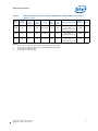
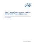
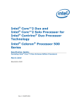
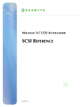
Intel® Xeon® Processor 7100 Series Specification Update March 2010 Notice: The Intel® Xeon® Processor 7100 Series may contain design defects or errors known as errata which may cause the product to deviate from published specifications. Current characterized errata are available on request. Order Number: 314554-006 INFORMATION IN THIS DOCUMENT IS PROVIDED IN CONNECTION WITH INTEL® PRODUCTS. EXCEPT AS PROVIDED IN INTEL'S TERMS AND CONDITIONS OF SALE FOR SUCH PRODUCTS, INTEL ASSUMES NO LIABILITY WHATSOEVER, AND INTEL DISCLAIMS ANY EXPRESS OR IMPLIED WARRANTY RELATING TO SALE AND/OR USE OF INTEL PRODUCTS, INCLUDING LIABILITY OR WARRANTIES RELATING TO FITNESS FOR A PARTICULAR PURPOSE, MERCHANTABILITY, OR INFRINGEMENT OF ANY PATENT, COPYRIGHT, OR OTHER INTELLECTUAL PROPERTY RIGHT. Intel products are not intended for use in medical, life saving, life sustaining, critical control or safety systems, or in nuclear facility applications. Intel may make changes to specifications and product descriptions at any time, without notice. Designers must not rely on the absence or characteristics of any features or instructions marked “reserved” or “undefined.” Intel reserves these for future definition and shall have no responsibility whatsoever for conflicts or incompatibilities arising from future changes to them. The Dual-Core Intel® Xeon® Processor 7100 Series Processor 7110, 7120, 7130, 7140 and 7150 may contain design defects or errors known as errata which may cause the product to deviate from published specifications. Current characterized errata are available on request. Contact your local Intel sales office or your distributor to obtain the latest specifications and before placing your product order. 1 Hyper-Threading Technology requires a computer system with an Intel® processor supporting HT Technology and a Hyper-Threading Technology enabled chipset, BIOS and operating system. Performance will vary depending on the specific hardware and software you use. See <<http:// www.intel.com/products/ht/hyperthreading_more.htm/>> for more information including details on which processors support HT Technology. Intel® 64 (Formerly Intel® EM64T) requires a computer system with a processor, chipset, BIOS, operating system, device drivers and applications enabled for Intel 64. Processor will not operate (including 32-bit operation) without an Intel 64 enabled BIOS. Performance will vary depending on your hardware and software configurations. See http://www.intel.com/technology/64bitextensions/ for more information including details on which processors support Intel 64 or consult with your system vendor for more information. ±Intel® Virtualization Technology requires a computer system with an enabled Intel® processor, BIOS, virtual machine monitor (VMM) and for some uses, certain platform software enabled for it. Functionality, performance or other benefit will vary depending on hardware and software configurations. Intel Virtualization Technology-enabled BIOS and VMM applications are currently in development. Δ Intel processor numbers are not a measure of performance. Processor numbers differentiate features within each processor family, not across different processor families. Over time processor numbers will increment based on changes in clock, speed, cache, FSB, or other features, and increments are not intended to represent proportional or quantitative increases in any particular feature. Current roadmap processor number progression is not necessarily representative of future roadmaps. See www.intel.com/products/processor_number for details. Enhanced HALT State (C1E) and Enhanced Intel SpeedStep® Technology (EIST) for specified units of this processor available Q4/06. See the Processor Spec Finder at http://processorfinder.intel.com or contact your Intel representative for more information. Celeron®, Celeron® D, Celeron® M, Intel® Core™, Intel® Core™ Duo, Intel® Core™ Solo, Intel NetBurst®, Intel® Xeon®, Mobile Intel®, Pentium® III Processor-M, Mobile Intel® Pentium® 4 Processor-M, Pentium® II, Pentium® II Xeon®, Pentium® III, Pentium® III Xeon® Pentium® 4, Pentium® D, Pentium® M, Pentium® Pro and the Intel® logo are trademarks or registered trademarks of Intel Corporation or its subsidiaries in the United States and other countries. Copies of documents which have an ordering number and are referenced in this document, or other Intel literature may be obtained by calling 1-800-548-4725 or by visiting Intel's website at http://developer.intel.com/design/litcentr. Copyright © 2010, Intel Corporation. All rights reserved. *Other names and brands may be claimed as the property of others. 2 Intel® Xeon® Processor 7100 Series Specification Update, March 2010 Contents Contents Revision History ........................................................................................................ 4 Preface ...................................................................................................................... 5 Package Markings...................................................................................................... 7 Identification Information ......................................................................................... 8 Summary Tables of Changes.................................................................................... 10 Errata ...................................................................................................................... 15 Specification Changes.............................................................................................. 26 Specification Clarifications ...................................................................................... 27 Documentation Changes .......................................................................................... 28 Intel® Xeon® Processor 7100 Series Specification Update, March 2010 3 Revision History Revision History Version 4 Description Date 001 Initial release of the Dual-Core Intel Xeon® Processor 7100 Sequence Specification Update. 002 Corrected Table 1, 2.6 GHz Processor Number. Added Erratum AL38. -003 Added Table 1, 3.50 GHz S-spec 7150 Processor Number Updated Related Documents Changed Intel® EM64T to Intel® 64 -004 Updated CPUID with Type, Extended Model and Extended Family. Updated Affected and Related Documents. Added Erratum AL39. May 2008 -005 Added Erratum AL40. May 2009 -006 Added Erratum AL41. March 2010 August 2006 September 2006 October 2006 Intel® Xeon® Processor 7100 Series Specification Update, March 2010 Preface Preface This document is an update to the specifications contained in the Affected Documents and Related Documents tables below. This document is a compilation of device and documentation errata, specification clarifications and changes. It is intended for hardware system manufacturers and software developers of applications, operating systems, or tools. Information types defined in Nomenclature are consolidated into the specification update and are no longer published in other documents. This document may also contain information that was not previously published. Affected Documents Document Title Dual-Core Intel® Xeon® Processor 7100 Series Datasheet Document Number/Location 314553 Related Documents Document Title AP-485, Intel® Processor Identification and the CPUID Instruction Intel® 64 and IA-32 Intel® Architectures Software Developer's Manual • • • • • Volume Volume Volume Volume Volume 1: Basic Architecture 2A: Instruction Set Reference, A-M 2B: Instruction Set Reference, N-Z 3A: System Programming Guide 3B: System Programming Guide Intel® 64 and IA-32 Intel® Architectures Optimization Reference Manual Intel® 64 and IA-32 Changes Intel® Architectures Software Developer's Manual Documentation Document Number/Location 241618 253665 253666 253667 253668 253669 248966 252046 64-bit Extension Technology Software Developer's Guide • • Volume I Volume 2 Intel® Virtualization Technology for IA-32 Processors (VT-x) Preliminary Specification 300834 300835 C97063 Nomenclature Errata are design defects or errors. These may cause the processor’s behavior to deviate from published specifications. Hardware and software designed to be used with any given stepping must assume that all errata documented for that stepping are present on all devices. Intel® Xeon® Processor 7100 Series Specification Update, March 2010 5 Preface S-Spec Number is a five-digit code used to identify products. Products are differentiated by their unique characteristics,e.g., core speed, L3 cache size, package type, etc. as described in the processor identification information table. Read all notes associated with each S-Spec number. Specification Changes are modifications to the current published specifications. These changes will be incorporated in any new release of the specification. Specification Clarifications describe a specification in greater detail or further highlight a specification’s impact to a complex design situation. These clarifications will be incorporated in any new release of the specification. Documentation Changes include typos, errors, or omissions from the current published specifications. These will be incorporated in any new release of the specification. Note: 6 Errata remain in the specification update throughout the product’s lifecycle, or until a particular stepping is no longer commercially available. Under these circumstances, errata removed from the specification update are archived and available upon request. Specification changes, specification clarifications and documentation changes are removed from the specification update when the appropriate changes are made to the appropriate product specification or user documentation (datasheets, manuals, etc.). Intel® Xeon® Processor 7100 Series Specification Update, March 2010 Package Markings Package Markings Dual-Core Intel® Xeon® Processor 7100 Series Package Markings Figure 1. Processor Top-Side Markings (Example) 2D 2D Matrix Matrix Includes Includes ATPO ATPO and andSerial Serial Number Number (front (frontend endmark) mark) Processor Name i(m) ©’05 ©’03 Pin 1 Indicator Figure 2. Processor Bottom-Side Markings (Example) Pin 1 Indicator Pin Field Cavity with Components 2D Matrix Includes ATPO and Serial Number (front end mark) Processor/Speed/Cache/Bus Number 7140M 3400/16M/800 SL9HA COSTA RICA S-Spec C0096109-0021 Country of Assy Text Line1 Text Line2 Text Line3 Intel® Xeon® Processor 7100 Series Specification Update, March 2010 FPO – Serial # (13 Characters) 7 Identification Information Identification Information The Intel® Xeon® Processor 7100 Series can be identified by the following register contents: Notes: Extended Family1 Extended Model2 Type3 Family4 Model5 L3 Cache Descriptor6 00000000b 0000b 00 1111b 0110b 0x49, 0x4A, 0x4B, 0x4C or 0x4D 1. 2. 3. 4. 5. 6. The Extended Family corresponds to bits [27:20] of the EDX register after RESET, bits [27:20] of the EAX register after the CPUID instruction is executed with a 1 in the EAX register, and the generation field of the Device ID register accessible through Boundary Scan. The Extended Model corresponds to bits [19:16] of the EDX register after RESET, bits [19:16] of the EAX register after the CPUID instruction is executed with a 1 in the EAX register, and the model field of the Device ID register accessible through Boundary Scan. The Type corresponds to bits [13:12] of the EDX register after RESET, bits [13:12] of the EAX register after the CPUID instruction is executed with a 1 in the EAX register, and the generation field of the Device ID register accessible through Boundary Scan. The Family corresponds to bits [11:8] of the EDX register after RESET, bits [11:8] of the EAX register after the CPUID instruction is executed with a 1 in the EAX register, and the generation field of the Device ID register accessible through Boundary Scan. The Model corresponds to bits [7:4] of the EDX register after RESET, bits [7:4] of the EAX register after the CPUID instruction is executed with a 1 in the EAX register, and the model field of the Device ID register accessible through Boundary Scan. Cache and TLB descriptor parameters are provided in the EAX, EBX, ECX and EDX registers after the CPUID instruction is executed with a 2 in the EAX register. The value returned is dependant on the L3 cache size of the processor installed, see Table 1. Cache and TLB descriptor parameters are provided in the EAX, EBX, ECX and EDX registers after the CPUID instruction is executed with a 2 in the EAX register. Please refer to the AP-485 Intel® Processor Identification and the CPUID Instruction Application Note for further information on the CPUID instruction. Dual-Core Intel® Xeon® Processor 7100 Series Identification Information (Sheet 1 of 2) Table 1. QDF/ S-Spec Core Stepping L2 Cache Size (bytes) L3 Cache Size (bytes) CPUID Core Freq (GHz) Data Bus Freq (MHz) Package and Revision Model Number Notes SL9YR B0 1M x 2 16M 00000F68h 3.50 667 604-pin micro-PGA with 53.3 x 53.3 mm FC-PGA6 packg Rev 02 7150N 1, 3 SL9HD B0 1M x 2 16M 00000F68h 3.33 667 604-pin micro-PGA with 53.3 x 53.3 mm FC-PGA6 packg Rev 02 7140N 1, 3 SL9HE B0 1M x 2 8M 00000F68h 3.16 667 604-pin micro-PGA with 53.3 x 53.3 mm FC-PGA6 packg Rev 02 7130N 1, 3 SL9HF B0 1M x 2 4M 00000F68h 3.00 667 604-pin micro-PGA with 53.3 x 53.3 mm FC-PGA6 packg Rev 02 7120N 2, 4 SL9QA B0 1M x 2 4M 00000F68h 2.50 667 604-pin micro-PGA with 53.3 x 53.3 mm FC-PGA6 packg Rev 02 7110N 2, 4 SL9HA B0 1M x 2 16M 00000F68h 3.40 800 604-pin micro-PGA with 53.3 x 53.3 mm FC-PGA6 packg Rev 02 7140M 1, 3 8 Intel® Xeon® Processor 7100 Series Specification Update, March 2010 Identification Information Dual-Core Intel® Xeon® Processor 7100 Series Identification Information (Sheet 2 of 2) Table 1. QDF/ S-Spec Core Stepping L2 Cache Size (bytes) L3 Cache Size (bytes) CPUID Core Freq (GHz) Data Bus Freq (MHz) Package and Revision Model Number Notes SL9HB B0 1M x 2 8M 00000F68h 3.20 800 604-pin micro-PGA with 53.3 x 53.3 mm FC-PGA6 packg Rev 02 7130M 1, 3 SL9HC B0 1M x 2 4M 00000F68h 3.00 800 604-pin micro-PGA with 53.3 x 53.3 mm FC-PGA6 packg Rev 02 7120M 2, 4 SL9Q9 B0 1M x 2 4M 00000F68h 2.60 800 604-pin micro-PGA with 53.3 x 53.3 mm FC-PGA6 packg Rev 02 7110M 2, 4 Notes: 1. 2. 3. 4. These These These These parts are parts are parts are parts are 5. enabled for Enhanced Intel SpeedStep®Technology (EIST). disabled for Enhanced Intel SpeedStep®Technology (EIST). enabled for TM2. disabled for TM2. Intel® Xeon® Processor 7100 Series Specification Update, March 2010 9 Summary Tables of Changes Summary Tables of Changes The following table indicates the Errata, Specification Changes, Specification Clarifications, or Documentation Changes which apply to the Dual-Core Intel Xeon Processor 7100 Series. Intel may fix some of the errata in a future stepping of the component, and account for the other outstanding issues through documentation or specification changes as noted. This table uses the following notations: Codes Used in Summary Table Stepping X: Errata exists in the stepping indicated. Specification Change or Clarification that applies to this stepping. (No mark) or (Blank box): This erratum is fixed in listed stepping or specification change does not apply to listed stepping. (Page): Page location of item in this document. Doc: Document change or update will be implemented. Plan Fix: This erratum may be fixed in a future stepping of the product. Fixed: This erratum has been previously fixed. No Fix: There are no plans to fix this erratum. Page Status Row Change bar to left of table row indicates this erratum is either new or modified from the previous version of the document. Each Specification Update item will be prefixed with a capital letter to distinguish the product. The key below details the letters that are used in Intel’s microprocessor Specification Updates: A= Dual-Core Intel® Xeon® processor 7000 sequence C= Intel® Celeron® processor D= Dual-Core Intel® Xeon® processor 2.80 GHz E= Intel® Pentium® III processor F= Intel® Pentium® processor Extreme Edition and Intel® Pentium® D processor I= Dual-Core Intel® Xeon® processor 5000 series J= 64-bit Intel® Xeon® processor MP with 1MB L2 cache K= Mobile Intel® Pentium® III processor L= Intel® Celeron® D processor M= Mobile Intel® Celeron® processor N= Intel® Pentium® 4 processor 10 Intel® Xeon® Processor 7100 Series Specification Update, March 2010 Summary Tables of Changes O= P= Q= R= S= T= U= V= W= X= Y= Z= AA = AB = AC = AD = AE = AF = AG = AH = AI = AJ = AK = AL = AM = AN = AO = AP = AQ = AR = AS = AT = AV = AW = AX = AY = AZ = AAA = AAB = AAC = AAD = Intel® Xeon® processor MP Intel® Xeon® processor Mobile Intel® Pentium® 4 processor supporting Hyper-Threading technology on 90-nm process technology Intel® Pentium® 4 processor on 90 nm process 64-bit Intel® Xeon® processor with 800 MHz system bus (1 MB and 2 MB L2 cache versions) Mobile Intel® Pentium® 4 processor-M 64-bit Intel® Xeon® processor MP with up to 8MB L3 cache Mobile Intel® Celeron® processor on .13 micron process in Micro-FCPGA package Intel® Celeron® M processor Intel® Pentium® M processor on 90nm process with 2-MB L2 cache and Intel® processor A100 and A110 with 512-KB L2 cache Intel® Pentium® M processor Mobile Intel® Pentium® 4 processor with 533 MHz system bus Intel® Pentium® D Processor 900 sequence and Intel® Pentium® processor Extreme Edition 955, 965 Intel® Pentium® 4 Processor 6x1 sequence Intel® Celeron® processor in 478 pin package Intel® Celeron® D processor on 65nm process Intel® Core™ Duo processor and Intel® Core™ Solo processor on 65nm process Dual-Core Intel® Xeon® processor LV Dual-Core Intel® Xeon® processor 5100 series Intel® Core™2 Duo/Solo Processor for Intel® Centrino® Duo Processor Technology’ Intel® Core™2 Extreme processor X6800Ä and Intel® Core™2 Duo desktop processor E6000Ä and E4000Ä sequence Quad-Core Intel® Xeon® processor 5300 series Intel® Core™2 Extreme quad-core processor QX6000Ä sequence and Intel® Core™2 Quad processor Q6000Ä sequence Dual-Core Intel® Xeon® processor 7100 series Intel® Celeron® processor 400 sequence Intel® Pentium® dual-core processor Quad-Core Intel® Xeon® processor 3200 series Dual-Core Intel® Xeon® processor 3000 series Intel® Pentium® dual-core desktop processor E2000Ä sequence Intel® Celeron processor 500 series Dual-Core Intel® Xeon® Processor 7200 Series and Quad-Core Intel® Xeon® Processor 7300 Series Intel® Celeron® Processor 200 Series Intel® Core™2 Extreme processor QX9000Ä series and Intel® Core™2 Quad processor Q9000Ä series Intel® Core™ 2 Duo processor E8000 series Quad-Core Intel® Xeon® processor 5400 series Dual-Core Intel® Xeon® processor 5200 series Intel® Core™2 Duo Processor and Intel® Core™2 Extreme Processor on 45nm Process Quad-Core Intel® Xeon® processor 3300 series Dual-Core Intel® Xeon® E3110 Processor Intel® Celeron® dual-core processor E1000 series Y = Intel® Pentium® M processor Intel® Core™2 Extreme Processor QX9775Δ Intel® Xeon® Processor 7100 Series Specification Update, March 2010 11 Summary Tables of Changes AAE = AAF = AAG = AAH = AAI = AAJ = AAK = AAL = Intel® Intel® Intel® Intel® Intel® Intel® Intel® Intel® Atom™ processor Z5xx series Atom™ processor 200 series Atom™ processor N series Atom™ Processor 300 series Xeon® Processor 7400 Series Core™ i7 and Intel® Core™ i7 Extreme Edition Xeon® Processor 5500 Series Pentium Dual-Core Processor E5000Δ Series The Specification Updates for the Pentium® processor, Pentium® Pro processor, and other Intel products do not use this convention. Errata (Sheet 1 of 2) No. B0 AL1 X No Fix “Bus Locks and SMC Detection May Cause the Processor to Hang Temporarily” AL2 X No Fix “Memory Aliasing of Pages As Uncacheable Memory Type and Write Back (WB) May Hang the System” AL3 X No Fix “Data Breakpoints on the High Half of a Floating Point Line Split May Not Be Captured” AL4 X No Fix “MOV CR3 Performs Incorrect Reserved Bit Checking When in PAE Paging” AL5 X No Fix “VMEntry from 64-bit Host to 32-bit Guest may Cause IERR# with Hyper-Threading Enabled” AL6 X No Fix “FXRSTOR May Not Restore Non-canonical Effective Addresses on Processors with Intel® 64 Enabled” AL7 X No Fix “A Push of ESP That Faults May Zero the Upper 32 Bits of RSP” AL8 X No Fix “Checking of Page Table Base Address May Not Match the Address Bit Width Supported by the Platform” AL9 X No Fix “With TF (Trap Flag) Asserted, FP Instruction That Triggers an Unmasked FP Exception May Take Single Step Trap before Retirement of Instruction” AL10 X No Fix “BTS (Branch Trace Store) and PEBS (Precise Event Based Sampling) May Update Memory outside the BTS/PEBS Buffer” AL11 X No Fix “Control Register 2 (CR2) Can be Updated during a REP MOVS/STOS Instruction with Fast Strings Enabled” AL12 X No Fix “REP STOS/MOVS Instructions with RCX >=2^32 May Cause a System Hang” AL13 X No Fix “A 64-Bit Value of Linear Instruction Pointer (LIP) May be Reported Incorrectly in the Branch Trace Store (BTS) Memory Record or in the Precise Event Based Sampling (PEBS) Memory Record” AL14 X No Fix “Access to an Unsupported Address Range in Uniprocessor (UP) or Dual-processor (DP) Systems Supporting Intel® Virtualization Technology May Not Trigger Appropriate Actions” AL15 X No Fix “Two Correctable L2 Cache Errors in Close Proximity May Cause a System Hang” AL16 X No Fix “Processor May Hang with a 25% or Less STPCLK# Duty Cycle” AL17 X No Fix “Machine Check Exceptions May not Update Last-Exception Record MSRs (LERs)” AL18 X No Fix “Writing the Local Vector Table (LVT) when an Interrupt is Pending May Cause an Unexpected Interrupt” AL19 X No Fix “L2 Cache ECC Machine Check Errors May be erroneously Reported after an Asynchronous RESET# Assertion” AL20 X No Fix “VMCALL to Activate Dual-monitor Treatment of SMIs and SMM Ignores Reserved Bit settings in VMexit Control Field” AL21 X No Fix “Using 2M/4M Pages When A20M# Is Asserted May Result in Incorrect Address Translations” AL22 X No Fix “Writing Shared Unaligned Data that Crosses a Cache Line without Proper Semaphores or Barriers May Expose a Memory Ordering Issue” AL23 X No Fix “The IA32_MC0_STATUS and IA32_MC1_STATUS Overflow Bit is not set when Multiple Un-correctable Machine Check Errors Occur at the Same Time” AL24 X No Fix “IRET under Certain Conditions May Cause an Unexpected Alignment Check Exception” 12 Plans Description Intel® Xeon® Processor 7100 Series Specification Update, March 2010 Summary Tables of Changes Errata (Sheet 2 of 2) No. B0 Plans Description AL25 X No Fix “Processor May Fault When the Upper 8 Bytes of Segment Selector Is Loaded from a Far Jump through a Call Gate via the Local Descriptor Table” AL26 X No Fix “The Processor May Issue Front Side Bus Transactions up to 6 Clocks after RESET# is Asserted” AL27 X No Fix “Front Side Bus Machine Checks May be Reported as a Result of On-Going Transactions during Warm Reset” AL28 X No Fix “NMI-blocking Information Recorded in VMCS May be Incorrect after a #GP on an IRET Instruction” AL29 X No Fix “VMLAUNCH/VMRESUME May Not Fail when VMCS is Programmed to Cause VM Exit to Return to a Different Mode” AL30 X No Fix “A Machine Check Exception (MCE) Occurring during an Enhanced Intel SpeedStep® Technology Ratio Change May Cause Both Processor Cores to Lock Up” AL31 X No Fix “BIST Error Reported on Secondary Logical Processor of Each Core” AL32 X No Fix “When Enhanced Halt State is Enabled and Thermal Monitor 2 is Disabled a System Hang may Occur” AL33 X No Fix “Lock Interaction between Two Logical Processors within a Core may Cause a Stall in Code Execution” AL34 X No Fix “Periodic Thermal Throttling/STPCLK Events in the Presence of High Memory Latency Accesses Could Lead to a System Hang” AL35 X Plan Fix “Reduced End-Agent Low side FSB Margin may occur with High Impedance Boards Operating at Low Temperatures” AL36 X No Fix “L3 Cache Errors Occurring During an INVD or WBINVD Instruction May not Generate a Machine Check Exception” AL37 X No Fix “A Continuous Loop Executing Bus Lock Transactions on One Logical Processor may Prevent Another Logical Processor from Acquiring Resource” AL38 X Plan Fix “Mid-Agent FSB Single-Bit Correctable Events may Occur with Certain Data Bus Lengths” AL39 X No Fix “A VM Exit Occuring in IA-32e Mode May Not Produce a VMX Abort When Expected” AL40 X No Fix “A Page Fault May Not be Generated When the PS bit is set to “1” in a PML4E or PDPTE” AL41 X No Fix “FP Data Operand Pointer May Be Incorrectly Calculated After an FP Access Which Wraps a 4-Gbyte Boundary in Code That Uses 32-Bit Address Size in 64-bit Mode” Intel® Xeon® Processor 7100 Series Specification Update, March 2010 13 Summary Tables of Changes Specification Changes No. 1 SPECIFICATION CHANGES 2D Matrix Added to the Bottom Side Laser Mark. Specification Clarifications No. SPECIFICATION CLARIFICATIONS None for this revision of this specification update. Documentation Changes No. DOCUMENTATION CHANGES None for this revision of this specification update. 14 Intel® Xeon® Processor 7100 Series Specification Update, March 2010 Errata Errata AL1. Bus Locks and SMC Detection May Cause the Processor to Hang Temporarily Problem: The processor may temporarily hang in an HT Technology enabled system if one logical processor executes a synchronization loop that includes one or more locks and is waiting for release by the other logical processor. If the releasing logical processor is executing instructions that are within the detection range of the self -modifying code (SMC) logic, then the processor may be locked in the synchronization loop until the arrival of an interrupt or other event. Implication: If this erratum occurs in an HT Technology enabled system, the application may temporarily stop making forward progress. Intel has not observed this erratum with any commercially available software. Workaround: None identified. Status: For the steppings affected, see the Summary Tables of Changes. AL2. Memory Aliasing of Pages As Uncacheable Memory Type and Write Back (WB) May Hang the System Problem: When a page is being accessed as either Uncacheable (UC) or Write Combining (WC) and WB, under certain bus and memory timing conditions, the system may loop in a continual sequence of UC fetch, implicit writeback, and Request For Ownership (RFO) retries. Implication: This erratum has not been observed in any commercially available operating system or application. The aliasing of memory regions, a condition necessary for this erratum to occur, is documented as being unsupported in the Intel® 64 and IA-32 Architectures Software Developer’s Manual, Volume 3, section 10.12.4, Programming the PAT. However, if this erratum occurs the system may hang. Workaround: The pages should not be mapped as either UC or WC and WB at the same time. Status: For the stepping affected, see the Summary Tables of Changes. AL3. Data Breakpoints on the High Half of a Floating Point Line Split May Not Be Captured Problem: When a floating point load which splits a 64-byte cache line gets a floating point stack fault, and a data breakpoint register maps to the high line of the floating point load, internal boundary conditions exist that may prevent the data breakpoint from being captured. Implication: When this erratum occurs, a data breakpoint will not be captured. Workaround: None identified. Status: For the steppings affected, see the Summary Tables of Changes. AL4. MOV CR3 Performs Incorrect Reserved Bit Checking When in PAE Paging Problem: The MOV CR3 instruction should perform reserved bit checking on the upper unimplemented address bits. This checking range should match the address width reported by CPUID instruction 0x8000008. This erratum applies whenever PAE is enabled. Implication: Software that sets the upper address bits on a MOV CR3 instruction and expects a fault may fail. This erratum has not been observed with commercially available software. Workaround: None identified. Intel® Xeon® Processor 7100 Series Specification Update, March 2010 15 Errata Status: For the steppings affected, see the Summary Tables of Changes. AL5. VMEntry from 64-bit Host to 32-bit Guest may Cause IERR# with Hyper-Threading Enabled Problem: When transitioning from a 64-bit host environment to a 32-bit guest environment via a VMEntry, internal conditions in a processor with Hyper-Threading enabled may cause a speculative page-table walk to be prematurely terminated, resulting in a processor hang and the assertion of IERR#. Implication: An IERR# may occur on VMEntry from a 64-bit to a 32-bit environment with HyperThreading enabled. Workaround: It is possible for the BIOS to contain a workaround for this erratum. Status: For the steppings affected, see the Summary Tables of Changes. AL6. FXRSTOR May Not Restore Non-canonical Effective Addresses on Processors with Intel® 64 Enabled Problem: If an x87 data instruction has been executed with a non-canonical effective address, FXSAVE may store that non-canonical FP Data Pointer (FDP) value into the save image. An FXRSTOR instruction executed with 64-bit operand size may signal a General Protection Fault (#GP) if the FDP or FP Instruction Pointer (FIP) is in non-canonical form. Implication: When this erratum occurs, Intel® 64 enabled systems may encounter an unintended #GP fault. Workaround: Software should avoid using non-canonical effective addressing in Intel® 64 enabled processors. BIOS can contain a workaround for this erratum removing the unintended #GP fault on FXRSTOR. Status: For the steppings affected, see the Summary Tables of Changes. AL7. A Push of ESP That Faults May Zero the Upper 32 Bits of RSP Problem: In the event that a push ESP instruction, that faults, is executed in compatibility mode, the processor will incorrectly zero upper 32-bits of RSP. Implication: A Push of ESP in compatibility mode will zero the upper 32-bits of RSP. Due to this erratum, this instruction fault may change the contents of RSP. This erratum has not been observed in commercially available software. Workaround: None identified. Status: For the steppings affected, see the Summary Tables of Changes. AL8. Checking of Page Table Base Address May Not Match the Address Bit Width Supported by the Platform Problem: If the page table base address, included in the page map level-4 table, page-directory pointer table, page-directory table or page table, exceeds the physical address range supported by the platform (e.g. 36-bit) and it is less than the implemented address range (e.g. 40-bit), the processor does not check if the address is invalid. Implication: If software sets such invalid physical address in those tables, the processor does not generate a page fault (#PF) upon access to that virtual address, and the access results in an incorrect read or write. If BIOS provides only valid physical address ranges to the operating system, this erratum will not occur. Workaround: BIOS must provide valid physical address ranges to the operating system. Status: 16 For the steppings affected, see the Summary Tables of Changes. Intel® Xeon® Processor 7100 Series Specification Update, March 2010 Errata AL9. With TF (Trap Flag) Asserted, FP Instruction That Triggers an Unmasked FP Exception May Take Single Step Trap before Retirement of Instruction Problem: If an FP instruction generates an unmasked exception with the EFLAGS.TF=1, it is possible for external events to occur, including a transition to a lower power state. When resuming from the lower power state, it may be possible to take the single step trap before the execution of the original FP instruction completes. Implication: A Single Step trap will be taken when not expected. Workaround: None identified. Status: For the steppings affected, see the Summary Tables of Changes. AL10. BTS (Branch Trace Store) and PEBS (Precise Event Based Sampling) May Update Memory outside the BTS/PEBS Buffer Problem: If the BTS/PEBS buffer is defined such that: The difference between BTS/PEBS buffer base and BTS/PEBS absolute maximum is not an integer multiple of the corresponding record sizes BTS/PEBS absolute maximum is less than a record size from the end of the virtual address space The record that would cross BTS/PEBS absolute maximum will also continue past the end of the virtual address space A BTS/PEBS record can be written that will wrap at the 4G boundary (IA32) or 2^64 boundary (Intel® 64 mode), and write memory outside of the BTS/PEBS buffer. Implication: Software that uses BTS/PEBS near the 4G boundary (IA32) or 2^64 boundary (Intel® 64 mode), and defines the buffer such that it does not hold an integer multiple of records can update memory outside the BTS/PEBS buffer. Workaround: Define BTS/PEBS buffer such that BTS/PEBS absolute maximum minus BTS/PEBS buffer base is integer multiple of the corresponding record sizes as recommended in the Intel® 64 and IA-32 Architectures Software Developer’s Manual, Volume 3. Status: For the steppings affected, see the Summary Tables of Changes. AL11. Control Register 2 (CR2) Can be Updated during a REP MOVS/STOS Instruction with Fast Strings Enabled Problem: Under limited circumstances while executing a REP MOVS/STOS string instruction, with fast strings enabled, it is possible for the value in CR2 to be changed as a result of an interim paging event, normally invisible to the user. Any higher priority architectural event that arrives and is handled while the interim paging event is occurring may see the modified value of CR2. Implication: The value in CR2 is correct at the time that an architectural page fault is signaled. Intel has not observed this erratum with any commercially available software. Workaround: None identified. Status: For the steppings affected, see the Summary Tables of Changes. AL12. REP STOS/MOVS Instructions with RCX >=2^32 May Cause a System Hang Problem: In IA-32e mode using Intel® 64 enabled processors, executing a repeating string instruction with the iteration count greater than or equal to 2^32 and a pending event may cause the REP STOS/MOVS instruction to live lock and hang. Implication: When this erratum occurs, the processor may live lock and result in a system hang. Intel has not observed this erratum with any commercially available software. Intel® Xeon® Processor 7100 Series Specification Update, March 2010 17 Errata Workaround: Do not use strings larger than 4 GB. Status: For the steppings affected, see the Summary Tables of Changes. AL13. A 64-Bit Value of Linear Instruction Pointer (LIP) May be Reported Incorrectly in the Branch Trace Store (BTS) Memory Record or in the Precise Event Based Sampling (PEBS) Memory Record Problem: On a processor supporting Intel® 64, If an instruction fetch wraps around the 4G boundary in Compatibility Mode, the 64-bit value of LIP in the BTS memory record will be incorrect (upper 32 bits will be set to FFFFFFFFh when they should be 0). If a PEBS event occurs on an instruction whose last byte is at memory location FFFFFFFFh, the 64-bit value of LIP in the PEBS record will be incorrect (upper 32 bits will be set to FFFFFFFFh when they should be 0). Implication: Intel has not observed this erratum on any commercially available software. Workaround: None identified. Status: For the steppings affected, see the Summary Tables of Changes. AL14. Access to an Unsupported Address Range in Uniprocessor (UP) or Dual-processor (DP) Systems Supporting Intel® Virtualization Technology May Not Trigger Appropriate Actions Problem: When using processors supporting Intel® Virtualization Technology and configured as dual- or single-processor-capable (i.e. not multiprocessor-capable), the processor should perform address checks using a maximum physical address width of 36. Instead, these processors will perform address checks using a maximum physical address width of 40. Implication: Due to this erratum, actions which are normally taken upon detection of an unsupported address may not occur. Software which does not attempt to access unsupported addresses will not experience this erratum. Workaround: None identified. Status: For the steppings affected, see the Summary Tables of Changes. AL15. Two Correctable L2 Cache Errors in Close Proximity May Cause a System Hang Problem: If two correctable L2 cache errors are detected in close proximity to each other, a livelock may occur as a result of the processor being unable to resolve this condition. Implication: When this erratum occurs, the processor may livelock and result in a system hang. Intel has only observed this erratum while injecting cache errors in simulation. Workaround: None identified. Status: For the steppings affected, see the Summary Tables of Changes. AL16. Processor May Hang with a 25% or Less STPCLK# Duty Cycle Problem: If a system de-asserts STPCLK# at a 25% or less duty cycle and the processor thermal control circuit (TCC) on-demand clock modulation is active, the processor may hang. This erratum does not occur under the automatic mode of the TCC. Implication: When this erratum occurs, the processor may hang. Workaround: If use of the on-demand mode of the processor's TCC is desired in conjunction with STPCLK# modulation, then assure that STPCLK# is not asserted at a 25% duty cycle. Status: 18 For the steppings affected, see the Summary Tables of Changes. Intel® Xeon® Processor 7100 Series Specification Update, March 2010 Errata AL17. Machine Check Exceptions May not Update Last-Exception Record MSRs (LERs) Problem: The Last-Exception Record MSRs (LERs) may not get updated when Machine Check Exceptions occur Implication: When this erratum occurs, the LER may not contain information relating to the machine check exception. They will contain information relating to the exception prior to the machine check exception. Workaround: None identified Status: For the steppings affected, see the Summary Tables of Changes. AL18. Writing the Local Vector Table (LVT) when an Interrupt is Pending May Cause an Unexpected Interrupt Problem: If a local interrupt is pending when the LVT entry is written, an interrupt may be taken on the new interrupt vector even if the mask bit is set. Implication: An interrupt may immediately be generated with the new vector when a LVT entry is written, even if the new LVT entry has the mask bit set. If there is no Interrupt Service Routine (ISR) set up for that vector the system will GP fault. If the ISR does not do an End of Interrupt (EOI) the bit for the vector will be left set in the in-service register and mask all interrupts at the same or lower priority. Workaround: Any vector programmed into an LVT entry must have an ISR associated with it, even if that vector was programmed as masked. This ISR routine must do an EOI to clear any unexpected interrupts that may occur. The ISR associated with the spurious vector does not generate an EOI, therefore the spurious vector should not be used when writing the LVT. Status: For the steppings affected, see the Summary Tables of Changes. AL19. L2 Cache ECC Machine Check Errors May be erroneously Reported after an Asynchronous RESET# Assertion Problem: Machine check status MSRs may incorrectly report the following L2 Cache ECC machine-check errors when cache transactions are in-flight and RESET# is asserted: • Instruction Fetch Errors (IA32_MC2_STATUS with MCA error code 153) • L2 Data Write Errors (IA32_MC1_STATUS with MCA error code 145) Implication: Uncorrected or corrected L2 ECC machine check errors may be erroneously reported. Intel has not observed this erratum on any commercially available system. Workaround: When a real run-time L2 Cache ECC Machine Check occurs, a corresponding valid error will normally be logged in the IA32_MC0_STATUS register. BIOS may clear IA32_MC2_STATUS and/or IA32_MC1_STATUS for these specific errors when IA32_MC0_STATUS does not have its VAL flag set. Status: For the steppings affected, see the Summary Tables of Changes. AL20. VMCALL to Activate Dual-monitor Treatment of SMIs and SMM Ignores Reserved Bit settings in VM-exit Control Field Problem: Processors supporting Intel® Virtualization Technology can execute VMCALL from within the Virtual Machine Monitor (VMM) to activate dual-monitor treatment of SMIs and SMM. Due to this erratum, if reserved bits are set to values inconsistent with VMX Capability MSRs, VMCALL may not VMFail. Implication: VMCALL executed to activate dual-monitor treatment of SMIs and SMM may not VMFail due to incorrect reserved bit settings in VM-Exit control field. Workaround: It is possible for the BIOS to contain a workaround for this erratum. Status: For the steppings affected, see the Summary Tables of Changes. Intel® Xeon® Processor 7100 Series Specification Update, March 2010 19 Errata AL21. Using 2M/4M Pages When A20M# Is Asserted May Result in Incorrect Address Translations Problem: An external A20M# pin if enabled forces address bit 20 to be masked (forced to zero) to emulates real-address mode address wraparound at 1 megabyte. However, if all of the following conditions are met, address bit 20 may not be masked: • paging is enabled • a linear address has bit 20 set • the address references a large page • A20M# is enabled Implication: When A20M# is enabled and an address references a large page the resulting translated physical address may be incorrect. This erratum has not been observed with any commercially available operating system. Workaround: Operating systems should not allow A20M# to be enabled if the masking of address bit 20 could be applied to an address that references a large page. A20M# is normally only used with the first megabyte of memory. Status: For the steppings affected, see the Summary Tables of Changes. AL22. Writing Shared Unaligned Data that Crosses a Cache Line without Proper Semaphores or Barriers May Expose a Memory Ordering Issue Problem: Software which is written so that multiple agents can modify the same shared unaligned memory location at the same time may experience a memory ordering issue if multiple loads access this shared data shortly thereafter. Exposure to this problem requires the use of a data write which spans a cache line boundary. Implication: This erratum may cause loads to be observed out of order. Intel has not observed this erratum with any commercially available software or system. Workaround: Software should ensure at least one of the following is true when modifying shared data by multiple agents: • The shared data is aligned • Proper semaphores or barriers are used in order to prevent concurrent data accesses Status: For the steppings affected, see the Summary Tables of Changes. AL23. The IA32_MC0_STATUS and IA32_MC1_STATUS Overflow Bit is not set when Multiple Un-correctable Machine Check Errors Occur at the Same Time Problem: When two enabled MC0/MC1 un-correctable machine check errors are detected in the same bank in the same internal clock cycle, the highest priority error will be logged in IA32_MC0_STATUS / IA32_MC1_STATUS register, but the overflow bit may not be set. Implication: The highest priority error will be logged and signaled if enabled, but the overflow bit in the IA32_MC0_STATUS/ IA32_MC1_STATUS register may not be set. Workaround: None identified. Status: For the steppings affected, see the Summary Tables of Changes. AL24. IRET under Certain Conditions May Cause an Unexpected Alignment Check Exception Problem: In IA-32e mode, it is possible to get an Alignment Check Exception (#AC) on the IRET instruction even though alignment checks were disabled at the start of the IRET. This can only occur if the IRET instruction is returning from CPL3 code to CPL3 code. IRETs from CPL0/1/2 are not affected. This erratum can occur if the EFLAGS value on the stack has the AC flag set, and the interrupt handler's stack is misaligned. In IA-32e mode, RSP is aligned to a 16-byte boundary before pushing the stack frame. 20 Intel® Xeon® Processor 7100 Series Specification Update, March 2010 Errata Implication: In IA-32e mode, under the conditions given above, an IRET can get a #AC even if alignment checks are disabled at the start of the IRET. This erratum can only be observed with a software generated stack frame. Workaround: Software should not generate misaligned stack frames for use with IRET. Status: For the steppings affected, see the Summary Tables of Changes. AL25. Processor May Fault When the Upper 8 Bytes of Segment Selector Is Loaded from a Far Jump through a Call Gate via the Local Descriptor Table Problem: In IA-32e mode of the Intel® 64 processor, control transfers through a call gate via the Local Descriptor Table (LDT) that uses a 16-byte descriptor, the upper 8-byte access may wrap and access an incorrect descriptor in the LDT. This only occurs on an LDT with a LIMIT>0x10008 with a 16-byte descriptor that has a selector of 0xFFFC. Implication: In the event this erratum occurs, the upper 8-byte access may wrap and access an incorrect descriptor within the LDT, potentially resulting in a fault or system hang. Intel has not observed this erratum with any commercially available software. Workaround: None identified. Status: For the steppings affected, see the Summary Tables of Changes. AL26. The Processor May Issue Front Side Bus Transactions up to 6 Clocks after RESET# is Asserted Problem: The processor may issue transactions beyond the documented 3 Front Side Bus (FSB) clocks and up to 6 FSB clocks after RESET# is asserted in the case of a warm reset. A warm reset is where the chipset asserts RESET# when the system is running. Implication: The processor may issue transactions up to 6 FSB clocks after the RESET# is asserted Workaround: None identified. Status: For the steppings affected, see the Summary Tables of Changes. AL27. Front Side Bus Machine Checks May be Reported as a Result of OnGoing Transactions during Warm Reset Problem: Processor Front Side Bus (FSB) protocol/signal integrity machine checks may be reported if the transactions are initiated or in-progress during a warm reset. A warm reset is where the chipset asserts RESET# when the system is running. Implication: The processor may log FSB protocol/signal integrity machine checks if transactions are allowed to occur during RESET# assertions. Workaround: BIOS may clear FSB protocol/signal integrity machine checks for systems/chipsets which do not block new transactions during RESET# assertions. Status: For the steppings affected, see the Summary Tables of Changes AL28. NMI-blocking Information Recorded in VMCS May be Incorrect after a #GP on an IRET Instruction Problem: In a system supporting Intel® Virtualization Technology, the NMI blocking bit in the Interruption-Information Field in the guest VMCS may be set incorrectly. This erratum will happen if a VMExit occurs for a #GP fault on an IRET instruction due to an EIP that violates the segment limit or is non-canonical. Implication: If this erratum occurs, monitor software may not be able to handle #GP and then inject an NMI since monitor software does not have information about whether NMIs are blocked in the guest. Workaround: Monitor software can workaround this bug by avoiding injection of NMI after #GP emulation. Status: For the steppings affected, see the Summary Tables of Changes. Intel® Xeon® Processor 7100 Series Specification Update, March 2010 21 Errata AL29. VMLAUNCH/VMRESUME May Not Fail when VMCS is Programmed to Cause VM Exit to Return to a Different Mode Problem: VMLAUNCH/VMRESUME instructions may not fail if the value of the "host address-space size" VM-exit control differs from the setting of IA32_EFER.LMA. Implication: Programming the VMCS to allow the monitor to be in different modes prior to VMLAUNCH/VMRESUME and after VM-exit may result in undefined behavior. Workaround: Software should ensure that "host address-space size" VM-exit control has the same value as IA32_EFER.LMA at the time of VMLAUNCH/VMRESUME. Status: For the steppings affected, see the Summary Tables of Changes. AL30. A Machine Check Exception (MCE) Occurring during an Enhanced Intel SpeedStep® Technology Ratio Change May Cause Both Processor Cores to Lock Up Problem: If an MCE and an Enhanced Intel SpeedStep® Technology frequency ratio change occur within a small timing window both processor cores may stop executing instructions. The MCERR# signal is correctly asserted for the Machine Check Exception. Implication: The system will stop operating. A hardware reset is required to recover form this condition. Intel has not observed this erratum with any commercially available software, or system. Workaround: None identified. Status: For the steppings affected, see the Summary Tables of Changes. AL31. BIST Error Reported on Secondary Logical Processor of Each Core Problem: The processor cores execute BIST (Built-in Self Test) after RESET if commanded by the Power-On Configuration setting. The secondary logical processor in each core will always declare a BIST failure. Implication: A false BIST failure may be detected on the secondary logical processor. Workaround: BIOS should use the primary logical processor BIST results for both the primary and secondary logical processors in each core. BIOS should ignore the BIST result in EAX [Bit13] for the secondary logical processor in each core. Status: For the steppings affected, see the Summary Tables of Changes. AL32. When Enhanced Halt State is Enabled and Thermal Monitor 2 is Disabled a System Hang may Occur Problem: With Enhanced Halt State (C1E) enabled and Thermal Monitor 2 (TM2) disabled a system hang may occur after the following sequence of events: 1. C1E is enabled. IA32_MISC_ENABLE MSR (1A0H), Bit [25] = 1. 2. TM2 is disabled. IA32_MISC_ENABLE MSR (1A0H), Bit [13] = 0. 3. All four threads of the processor enter the C1E state. 4. FORCEPR# is asserted. (This may happen if a different processor asserts PROCHOT# and the system asserts FORCEPR# to all sockets in response.) 5. While FORCEPR# is still active, an Interrupt is accepted that causes the processor to exit the C1E state. Intel® Xeon® Processor 7100 Series, processor numbers 7140 and 7130 are affected by this erratum. Processor numbers 7120 and 7110 are not affected by this erratum. Software may use the IA32_PLATFORM_ID MSR (17H), Bits[52:50] to determine if the processor is affected. A Platform ID of ‘001’ (Processor Flag 1) is affected and Platform ID of ‘101’ (Processor Flag 5) is not affected by this erratum. 22 Intel® Xeon® Processor 7100 Series Specification Update, March 2010 Errata Implication: A system hang may occur. Intel has not observed this erratum with any commercially available software. Workaround: Enable TM2, IA32_MISC_ENABLE MSR (1A0H), Bit [13] = 1. Status: For the steppings affected, see the Summary Tables of Changes. AL33. Lock Interaction between Two Logical Processors within a Core may Cause a Stall in Code Execution Problem: Problem: A logical processor may temporarily stall code execution in an HT Technology enabled system when the following sequence occurs: 1. A logical processor executes a tight synchronization loop that includes a stream of locks, which propagate to the FSB. This will not occur if the lock access is satisfied from the internal cache. 2. The second logical processor within the same| core executes other instructions. Logical processors that are not within the same core are not affected by this issue. Locks that are not split across a cache line and execute from write-back cacheable memory will not cause this issue. The interaction must occur in a particular timing window which may cause the logical processor in the synchronization sequence to stall until the arrival of an interrupt or other FSB transaction. Implication: If this erratum occurs in an HT Technology enabled system, the affected application may temporarily stop making forward progress. Intel has not observed this erratum with any commercially available software. Workaround: None identified. Status: For the steppings affected, see the Summary Tables of Changes AL34. Periodic Thermal Throttling/STPCLK Events in the Presence of High Memory Latency Accesses Could Lead to a System Hang Problem: The system may hang when the following conditions are met: • Periodic STPCLK mechanism is enabled via the chipset or the processor enters thermal throttling from activation of the thermal control circuit (TCC). • Hyper-Threading Technology is enabled. • One logical processor is trying to service an event (i.e. hardware interrupt). • The other logical processor executes code and the latency for any memory accesses are long enough for STPCLK to be re-asserted or the processor re-enters throttling. Implication: If this erratum occurs, the processor will go into and out of the sleep state or thermal throttling without making forward progress, since the logical processor will not be able to service any pending event. Intel has not observed this erratum with any commercially available software or system. Workaround: None identified. Status: For the steppings affected, see the Summary Tables of Changes. AL35. Reduced End-Agent Low side FSB Margin may occur with High Impedance Boards Operating at Low Temperatures Problem: With a fully populated (end-agent processor, mid-agent processor and chipset) FSB operating at 800 MTS (Mega Transfers per Second), certain Intel® 8501 Chipset North Bridge components may cause the end-agent processor to post FSB single-bit correctable (SBC) events. This occurs more frequently on a high impedance board operating at low temperatures. Implication: There is no functional impact to the system, it will continue to run with no performance impact. The system may see an increase in FSB SBC events, which result in a posting Intel® Xeon® Processor 7100 Series Specification Update, March 2010 23 Errata to the MC4_STATUS MSR (411H). A Machine Check exception is not generated on an SBC event. Workaround: It is possible for the BIOS to contain a workaround for this erratum. Status: For the steppings affected, see the Summary Tables of Changes. AL36. L3 Cache Errors Occurring During an INVD or WBINVD Instruction May not Generate a Machine Check Exception Problem: L3 Cache Errors which occur during a INVD or WBINVD instruction may not generate a Machine Check Exception. Implication: The L3 Cache error is not reported. Intel has not observed this erratum with any commercially available software, or system. Workaround: None identified. Status: For the steppings affected, see the Summary Tables of Changes. AL37. A Continuous Loop Executing Bus Lock Transactions on One Logical Processor may Prevent Another Logical Processor from Acquiring Resource Problem: In a system supporting Hyper-Threading Technology, when one hardware thread is in a continuous loop executing bus locks plus other traffic, the other hardware thread may be prevented from acquiring resources to also execute a lock. Implication: This erratum may cause system hang or unpredictable system behavior. This erratum has not been observed with commercially available software. Workaround: None identified. Status: For the steppings affected, see the Summary Tables of Changes. AL38. Mid-Agent FSB Single-Bit Correctable Events may Occur with Certain Data Bus Lengths Problem: A fully populated (end-agent processor, mid-agent processor and Intel® 8501Chipset North Bridge) FSB (Front Side Bus) operating at 800 MTS (Mega Transfers per Second) may cause the mid-agent processor to post FSB single-bit correctable (SBC) events when the end-agent to mid-agent data bus trace length is greater than 4.75 inches. Implication: There is no functional impact to the system, it will continue to run with no performance impact. The system may see FSB SBC events, which result in a posting to the IA32_MC4_STATUS MSR (411H). A Machine Check exception is not generated on an SBC event. This erratum has not been observed with commercially available software. Workaround: It is possible for the BIOS to contain a workaround for this erratum. Status: For the steppings affected, see the Summary Tables of Changes. AL39. A VM Exit Occuring in IA-32e Mode May Not Produce a VMX Abort When Expected Problem: If a VM exit occurs while the processor is in IA-32e mode and the “host address-space size” VM-exit control is 0, a VMX abort should occur. Due to this erratum, the expected VMX aborts may not occur and instead the VM Exit will occur normally. The conditions required to observe this erratum are a VM entry that returns from SMM with the “IA32e guest” VM-entry control set to 1 in the SMM VMCS and the “host address-space size” VM-exit control cleared to 0 in the executive VMCS. Implication: A VM Exit will occur when a VMX Abort was expected. Workaround: An SMM VMM should always set the “IA-32e guest” VM-entry control in the SMM VMCS to be the value that was in the LMA bit (IA32_EFER.LMA.LMA[bit 10]) in the IA32_EFER MSR (C0000080H) at the time of the last SMM VM exit. If this guideline is followed, that value will be 1 only if the “host address-space size” VM-exit control is 1 in the executive VMCS. 24 Intel® Xeon® Processor 7100 Series Specification Update, March 2010 Errata Status: For the steppings affected, see the Summary Tables of Changes. AL40. A Page Fault May Not be Generated When the PS bit is set to “1” in a PML4E or PDPTE Problem: On processors supporting Intel® 64 architecture, the PS bit (Page Size, bit 7) is reserved in PML4Es and PDPTEs. If the translation of the linear address of a memory access encounters a PML4E or a PDPTE with PS set to 1, a page fault should occur. Due to this erratum, PS of such an entry is ignored and no page fault will occur due to its being set. Implication: Software may not operate properly if it relies on the processor to deliver page faults when reserved bits are set in paging-structure entries. Workaround: Software should not set bit 7 in any PML4E or PDPTE that has Present Bit (Bit 0) set to “1”. Status: For the steppings affected, see the Summary Tables of Changes. AL41. FP Data Operand Pointer May Be Incorrectly Calculated After an FP Access Which Wraps a 4-Gbyte Boundary in Code That Uses 32-Bit Address Size in 64-bit Mode Problem: The FP (Floating Point) Data Operand Pointer is the effective address of the operand associated with the last non-control FP instruction executed by the processor. If an 80bit FP access (load or store) uses a 32-bit address size in 64-bit mode and the memory access wraps a 4-Gbyte boundary and the FP environment is subsequently saved, the value contained in the FP Data Operand Pointer may be incorrect. Implication: Due to this erratum, the FP Data Operand Pointer may be incorrect. Wrapping an 80-bit FP load around a 4-Gbyte boundary in this way is not a normal programming practice. Intel has not observed this erratum with any commercially available software. Workaround: If the FP Data Operand Pointer is used in a 64-bit operating system which may run code accessing 32-bit addresses, care must be taken to ensure that no 80-bit FP accesses are wrapped around a 4-Gbyte boundary. Status: For the steppings affected, see the Summary Table of Changes. Intel® Xeon® Processor 7100 Series Specification Update, March 2010 25 Specification Changes Specification Changes The Specification Changes listed in this section apply to the following documents: 1. Dual-Core Intel® Xeon® Processor 7100 Series Datasheet All Specification Changes will be incorporated into a future version of the appropriate Dual-Core Intel Xeon Processor 7100 Series documentation. 1. 2D Matrix Added to the Bottom Side Laser Mark Figure 4-5. Processor Bottom-Side Markings has been updated to include a 2D Matrix. Figure 4-5. Processor Bottom-Side Markings Pin 1 Indicator Pin Field Cavity with Components 2D Matrix Includes ATPO and Serial Number (front end mark) Processor/Speed/Cache/Bus Number 7140M 3400/16M/800 SL9HA COSTA RICA S-Spec C0096109-0021 Country of Assy Text Line1 Text Line2 Text Line3 26 FPO – Serial # (13 Characters) Intel® Xeon® Processor 7100 Series Specification Update, March 2010 Specification Clarifications Specification Clarifications There are no new Specification Clarifications for this revision. The Specification Clarifications listed in this section apply to the following documents: 1. Dual-Core Intel® Xeon® Processor 7100 Series Datasheet All Specification Clarifications will be incorporated into a future version of the appropriate Dual-Core Intel® Xeon® Processor 7100 Series documentation. Δ Intel processor numbers are not a measure of performance. Processor numbers differentiate features within each processor family, not across different processor families. Over time processor numbers will increment based on changes in clock, speed, cache, FSB, or other features, and increments are not intended to represent proportional or quantitative increases in any particular feature. Current roadmap processor number progression is not necessarily representative of future roadmaps. See www.intel.com/products/processor_number for details. Intel® Xeon® Processor 7100 Series Specification Update, March 2010 27 Documentation Changes Documentation Changes There are no new Documentation Changes for this revision. The Documentation Changes listed in this section apply to the following documents: 1. Dual-Core Intel® Xeon® Processor 7100 Series Datasheet All Documentation Changes will be incorporated into a future version of the appropriate Dual-Core Intel® Xeon® Processor 7100 Series documentation. Note: Documentation changes for Intel® 64 and IA-32 Architectures Software Developer’s Manual volumes 1, 2A, 2B, 3A and 3B will be posted in the separate document Intel® 64 and IA-32 Architectures Software Developer’s Manual Documentation Changes. Follow the link below to become familiar with this file. http://developer.intel.com/design/processor/specupdt/252046.htm § 28 Intel® Xeon® Processor 7100 Series Specification Update, March 2010 Documentation Changes Intel® Xeon® Processor 7100 Series Specification Update, March 2010 29