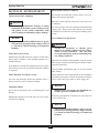
1
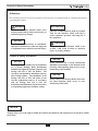
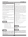
Cascade Multiple Boiler Distribution
Manifold and Hydronic Junction for
PRESTIGE Solo 250 or PRESTIGE Solo 399 Boilers
WARNING
NOTICE
Revised 3/25/13
This document is intended to be used by a qualified heating contractor or service
technician. Read all instructions within this document, the PRESTIGE Boiler
Installation and Maintenance Manual and Prestige Vent Supplement before proceeding with the installation. It is recommended to follow the procedures in the steps
given, skipping or missing procedural steps could result in severe personal injury,
death or substantial property damage.
Installation of boilers must comply with local requirements and codes and with the
National Fuel Gas Code NFPA 54, ANSI Z223.1 for installations within the U.S. For
installations in Canada the installation must comply with CAN/CSA B149.1.
2011-40 Prestige Cascade Manual
Table of Contents
PRODUCT & SAFETY INFORMATION
Definitions . . . . . . . . . . . . . . . . . . . . . . . . . . . . . . . . . . . . . . . . . . . . . . . . . . . . . . . 1
Product and Safety Information . . . . . . . . . . . . . . . . . . . . . . . . . . . . . . . . . . . . . . . 1
SECTION I – PRE-INSTALLATION ITEMS
Code Compliance. . . . . . . . . . . . . . . . . . . . . . . . . . . . . . . . . . . . . . . . . . . . . . . . . . . 2
Determine Location . . . . . . . . . . . . . . . . . . . . . . . . . . . . . . . . . . . . . . . . . . . . . . . . 2
Recommended Clearances. . . . . . . . . . . . . . . . . . . . . . . . . . . . . . . . . . . . . . . . . . . . 2
Cascade Kit Components. . . . . . . . . . . . . . . . . . . . . . . . . . . . . . . . . . . . . . . . . . . . . 2
Operating Restrictions . . . . . . . . . . . . . . . . . . . . . . . . . . . . . . . . . . . . . . . . . . . . . . . 2
Kit Component Diagrams and Tables . . . . . . . . . . . . . . . . . . . . . . . . . . . . . . . . . . 3-19
SECTION II – COMBUSTION AIR AND VENTING
Combustion Air and Venting . . . . . . . . . . . . . . . . . . . . . . . . . . . . . . . . . . . . . . . . . . 20-21
SECTION III – INSTALLATION
Distribution Manifold . . . . . . . . . . . . . . . . . . . . . . . . . . . . . . . . . . . . . . . . . . . . . . . 22
Multiple Distribution Manifolds . . . . . . . . . . . . . . . . . . . . . . . . . . . . . . . . . . . . . . . 22
Hydronic Junction . . . . . . . . . . . . . . . . . . . . . . . . . . . . . . . . . . . . . . . . . . . . . . . . . . 23
Insulation . . . . . . . . . . . . . . . . . . . . . . . . . . . . . . . . . . . . . . . . . . . . . . . . . . . . . . . . 23
Boiler Mounting . . . . . . . . . . . . . . . . . . . . . . . . . . . . . . . . . . . . . . . . . . . . . . . . . . . 24
SECTION IV – BOILER PIPING
General. . . . . . . . . . . . . . . . . . . . . . . . . . . . . . . . . . . . . . . . . . . . . . . . . . . . . . . . . . . 25
SECTION V – CSD-1 PIPING & CONTROL INSTALLATION
P/S or R/R with Valves Kit - PSCAS17 . . . . . . . . . . . . . . . . . . . . . . . . . . . . . . . . . 26
Reverse Return (R/R) . . . . . . . . . . . . . . . . . . . . . . . . . . . . . . . . . . . . . . . . . . . . . . . 26
SECTION VI – SYSTEM PIPING
Multiple Distribution Manifolds . . . . . . . . . . . . . . . . . . . . . . . . . . . . . . . . . . . . . . . 27
System Piping . . . . . . . . . . . . . . . . . . . . . . . . . . . . . . . . . . . . . . . . . . . . . . . . . . . . . 27-28
High Pressure Systems or Involving Fluid Separation . . . . . . . . . . . . . . . . . . . . . 29
System Piping Diagrams . . . . . . . . . . . . . . . . . . . . . . . . . . . . . . . . . . . . . . . . . . . . . 30-35
SECTION VII – GAS PIPING
Natural Gas Pipe Sizing . . . . . . . . . . . . . . . . . . . . . . . . . . . . . . . . . . . . . . . . . . . . . 36
Propane Gas Pipe Sizing . . . . . . . . . . . . . . . . . . . . . . . . . . . . . . . . . . . . . . . . . . . . 36
i
Table of Contents
SECTION VIII – WIRING
Power Supply . . . . . . . . . . . . . . . . . . . . . . . . . . . . . . . . . . . . . . . . . . . . . . . . . . . . . 37
Multiple Boiler Control . . . . . . . . . . . . . . . . . . . . . . . . . . . . . . . . . . . . . . . . . . . . . 37
CSD-1 P/S or R/R with Valves Kit . . . . . . . . . . . . . . . . . . . . . . . . . . . . . . . . . . . . . 37
CSD-1 R/R . . . . . . . . . . . . . . . . . . . . . . . . . . . . . . . . . . . . . . . . . . . . . . . . . . . . . . . 37
Field Wiring Diagrams . . . . . . . . . . . . . . . . . . . . . . . . . . . . . . . . . . . . . . . . . . . . . . 38-40
SECTION IX – SYSTEM START-UP
Check System Water Chemistry . . . . . . . . . . . . . . . . . . . . . . . . . . . . . . . . . . . . . . . 41
Water pH Level 6.0 to 8.0 . . . . . . . . . . . . . . . . . . . . . . . . . . . . . . . . . . . . . . . . . . . 41
Water Hardness Less Than 7 Grains . . . . . . . . . . . . . . . . . . . . . . . . . . . . . . . . . . . 41
Chlorinated Water . . . . . . . . . . . . . . . . . . . . . . . . . . . . . . . . . . . . . . . . . . . . . . . . . . 41
Flush System to Remove Sediment . . . . . . . . . . . . . . . . . . . . . . . . . . . . . . . . . . . . 41
Use of Antifreeze in the System . . . . . . . . . . . . . . . . . . . . . . . . . . . . . . . . . . . . . . . 41
Check and Test Antifreeze . . . . . . . . . . . . . . . . . . . . . . . . . . . . . . . . . . . . . . . . . . . 42
SECTION X – MAINTENANCE SCHEDULE
Service Technician – General . . . . . . . . . . . . . . . . . . . . . . . . . . . . . . . . . . . . . . . . . 43
Owner Maintenance . . . . . . . . . . . . . . . . . . . . . . . . . . . . . . . . . . . . . . . . . . . . . . . . 43
SECTION XI – MAINTENANCE PROCEDURES
Maintenance Procedures . . . . . . . . . . . . . . . . . . . . . . . . . . . . . . . . . . . . . . . . . . . . . 44
Reported Problems . . . . . . . . . . . . . . . . . . . . . . . . . . . . . . . . . . . . . . . . . . . . . . . . . 44
Check Surrounding Area . . . . . . . . . . . . . . . . . . . . . . . . . . . . . . . . . . . . . . . . . . . . 44
Check System Piping . . . . . . . . . . . . . . . . . . . . . . . . . . . . . . . . . . . . . . . . . . . . . . . 44
Check Boiler/Cascade System . . . . . . . . . . . . . . . . . . . . . . . . . . . . . . . . . . . . . . . . 44
Check Expansion Tank . . . . . . . . . . . . . . . . . . . . . . . . . . . . . . . . . . . . . . . . . . . . . . 44
Check Boiler Relief Valve . . . . . . . . . . . . . . . . . . . . . . . . . . . . . . . . . . . . . . . . . . . . 45
REPLACEMENT PARTS
Replacement Parts . . . . . . . . . . . . . . . . . . . . . . . . . . . . . . . . . . . . . . . . . . . . . . . . . . 46-51
PRODUCT SPECIFICATIONS
Specifications . . . . . . . . . . . . . . . . . . . . . . . . . . . . . . . . . . . . . . . . . . . . . . . . . . . . . 52-59
ii
Product & Safety Information
Definitions
The following terms are used to bring attention to the presence of potential hazards or important information
concerning the product.
BEST PRACTICE
WARNING
Indicates a hazardous situation which, if not
avoided, could result in death, serious injury or
substantial property damage.
Indicates recommendations made by Triangle
Tube for the installers which will help to
ensure optimum operation and longevity of
the equipment.
NOTICE
CAUTION
Indicates special instructions on installation,
operation or maintenance, which are important
to equipment but not related to personal injury.
Indicates a hazardous situation which, if not
avoided, could result in minor or moderate
injury or property damage.
Product & Safety Information
NOTICE
NOTICE
Please reference the Cascade Distribution
Manifold serial number on the inclined section
of left leg when inquiring about service or troubleshooting of the manifold.
This supplement is intended for the installation
of a Cascade Multiple Boiler Distribution
Manifold and Optional Hydronic Junction with
Prestige Solo 250 or Solo 399 Boilers. The
Cascade is not intended for installation with any
other Prestige Boilers. The installation of the
Prestige Solo 250 or Solo 399 boilers in the
Cascade configuration must be in accordance
with the Prestige Solo 250 or Solo 399
Installation and Maintenance Manual and other
corresponding supplements including venting.
NOTICE
Please reference the Prestige Boiler serial number when inquiring about service or troubleshooting of the boiler.
NOTICE
Triangle Tube reserves the right to modify the technical specifications and components of its products without
prior notice.
1
Pre-Installation Items
SECTION I – PRE-INSTALLATION ITEMS
Consult local codes for any additional clearance requirements.
Code Compliance
Cascade Kit Components
Installation of the Cascade must comply with local codes
and requirements and with the latest edition of National
Fuel Gas Code NFPA 54, ANSI Z223.1 for installations
in the U.S. For Installations in Canada, the installations
must comply with latest edition of CAN/CSA B149.1.
The Cascade must be fully constructed using ONLY the
components from Triangle Tube.
Prior to installation, check to ensure all parts required for
the completion of the Cascade are present. See Figures
1- 6 and Tables 1 and 2, pages 3-8 for complete breakdown of Solo 250 boiler cascade kit components. See
Figures 7-9 and Table 3 pages 9-10 for optional Solo
250 boiler reverse return with valve kit and kit components. See Figures 10 - 15 and Tables 4 and 5, pages 1116 for complete breakdown of Solo 399 boiler cascade
kit components. See Figures 16-18 and Table 6 pages
17-18 for optional Solo 399 boiler reverse return with
valve kit and kit components. See page 19 for optional
kits and kit components for both Solo 250 & 399 boilers.
Determine Location
Operating Restrictions
Consider the following; piping, venting, gas, electric and
drain when selecting a location for the Cascade.
•
Maximum water temperature is 200ºF
•
Maximum working pressure for PRESTIGE Solo
250 Boilers is 30 psig.
•
Maximum working pressure for PRESTIGE Solo
399 Boilers is 30 psig.
•
Maximum working pressure for PRESTIGE Solo
399HP is 80 psig.
•
Maximum working pressure for Cascade Manifold
is 80 psig.
•
pH and chloride limits for water heaters are:
The installation of the Cascade must be installed in
accordance with the Standards for Controls and Safety
Devices for Automatically Fired Boilers ANSI/ASME
CSD-1 (CSD-1) when required.
Recommended Clearances
The PRESTIGE Solo 250 or Solo 399 is approved for
zero clearances to combustibles, excluding vent and
boiler piping.
-
Vent & Boiler Piping – ¼” from combustible materials
BEST PRACTICE
To provide serviceability it is recommended that the following clearances be maintained from the Cascade:
- chloride, less than 150 mg/l (ppm)
-pH value min. 6 - max. 8
- Top boiler jackets – 24 inches
- Front boiler jackets – 24 inches
- Bottom boiler jackets – 24 inches
NOTICE
- Rear of boiler jacket – 13 inches
Any water conditioning system must be installed
and maintained in accordance with manufacturer’s
specifications.
- Left side of outer left boiler jacket – 9 inches
- Right side of outer right boiler jacket – 9 inches
NOTICE
WARNING
Do not install the Cascade on any application if the
system piping contains non-oxygen barrier tubing or
if the system is considered an “open system”.
Exposing the Cascade to oxygen contamination will
lead to premature failure and denial of the warranty.
If the clearances listed above cannot be maintained
for the Cascade or the enclosure in which the
Cascade is installed is less than 85 cubic feet per
Prestige Boiler, the space must be ventilated, see
Prestige Installation and Maintenance Manual for
ventilation requirements.
2
3
See Figure 2,
Page 4
See Figure 3,
Page 4
5
Fig. 1: Cascade Kit Components for Solo 250 Boilers – Primary Secondary (P/S) - See Table 1, Page 5
22 21
9 8 7 2
1 10
4
3 6 8 9
Pre-Installation Items
Pre-Installation Items
15
5
24
11
25
14
5
12
13
23
Fig. 2: Cascade Kit Components for Solo 250 Boilers – Primary Secondary Supply Piping- See Table 1, Page 5
15
5
16
17 18 19
20
13
12
Fig. 3: Cascade Kit Components for Solo 250 Boilers – Primary Secondary Return Piping - See Table 1, Page 5
4
Pre-Installation Items
Table 1: Cascade Kit Components for Solo 250 Boilers – Primary Secondary (P/S) - See Figs. 1 - 3, Pages 3 & 4
CPS 500
CPS1000
Kit Components
Item
Quantity
1
Prestige Solo 250 Boiler
2
4
2
2 Boiler Manifold
1
2
3
Hydronic Junction with Insulation & Air Vent
1
1
4
1-1/4” NPT 90° Elbow
1
1
5
1-1/4” NPT x 4” Nipple
7
13
6
Flange - ANSI to 3" NPSC
2
2
7
Flange - ANSI to Blind
2
2
8
Gasket - ANSI
6
8
9
Flared Bolt & Nut – Flange (5/8-11 x 3”)
24
32
10
Bolt, Washer & Nut – Boiler Mounting Bracket (5/16-18 x ¾”)
4
8
11
1-1/2” NPT Union/Shut Off Valve Assembly
2
4
12
1-1/2” NPT 90° Street Elbow
4
8
13
1-1/2” NPT x 13” Flexible Hose/Union Assembly
4
8
14
1-1/2” NPT x Close Nipple
2
4
15
1-1/4” NPT Union
4
8
16
1-1/4” NPT Drain/Shut Off Valve/Circulator Flange Assembly
2
4
17
Circulator – Grundfos UPS 15-58
2
4
18
Gasket – Circulator
4
8
19
Bolt & Nut - Circulator
8
16
20
1-1/2” NPT Circulator Flange/Shut Off Valve Assembly
2
4
21
Heavy-Duty Concrete Anchors with Washer & Nut
4
8
22
Concrete Drill Bit
1
2
23
1-1/2” NPT & 1 1/4” NPT 90º Reducing Elbow 2
2
4
24
1-1/4” NPT x 1/2” NPT x 1-1/4” NPT Inline Reducing Tee
2
4
25
1/2” NPT Plug
2
4
5
6
See Figure 5,
Page 7
See Figure 6,
Page 7
4 5 6
2 3 5 6
Fig. 4: Cascade Kit Components for Solo 250 Boilers – Reverse Return (R/R) - See Table 2, Page 8
16 15
6 5 3
6 5 4
1 7
Pre-Installation Items
Pre-Installation Items
17
8
12
9
19
18
12
13
11
10
Fig. 5: Cascade Kit Components for Solo 250 Boilers - Reverse Return Supply Piping - See Table 2, Page 8
17
14
10
11
Fig. 6: Cascade Kit Components for Solo 250 Boilers - Reverse Return Return Piping - See Table 2, Page 8
7
Pre-Installation Items
Table 2: Cascade Kit Components for Solo 250 Boilers Reverse Return (R/R) - See Figs, 4-6, Pages 6&7
CRR500
Item
CRR1000
Kit Components
Quantity
1
Prestige Solo 250 Boiler
2
4
2
2 Boiler Manifold
1
2
3
Flange - ANSI to 3" NPSC
2
2
4
Flange - ANSI to Blind
2
2
5
Gasket - ANSI
4
6
6
Flared Bolt & Nut – Flange (5/8-11 x 3”)
16
24
7
Bolt, Washer & Nut – Boiler Mounting Bracket
(5/16-18 x ¾”)
4
8
8
1-1/2” NPT Union
2
4
9
1-1/2” NPT x 4” Nipple
2
4
10
1-1/2” NPT x 1 1/4” NPT 90° Reducing Elbow
4
8
11
1-1/2” NPT x 13” Flexible Hose/Union Assembly
4
8
12
1-1/4” NPT x 4” Nipple
4
8
13
1-1/2” NPT 90° Street Elbow
2
4
14
1-1/4” NPT x 13” Pipe
2
4
15
Heavy-Duty Concrete Anchors with Washer & Nut
4
8
16
Concrete Drill Bit
1
2
17
1-1/4” NPT Union
4
8
18
1-1/4” NPT x 1/2” NPT x 1 1/4” NPT Inline Reducing Tee
2
4
19
1/2” NPT Plug
2
4
BEST PRACTICE
It’s recommended to install Reverse Return with Valves to allow for isolation of an individual boiler for servicing.
8
9
See Figure 9,
Page 10
Fig. 7: Optional Kit Components for Solo 250 – R/R with Valves - Shut Off & Drain - See Table 3, Page 10
See Figure 8,
Page 10
Pre-Installation Items
Pre-Installation Items
1
Supplied in Standard
Reverse Return Kits (CRR)
2
Fig. 8: Optional Kit Components for Solo 250 Boilers– R/R with Valves Supply Piping - See Table 3
3
4
Supplied in Standard
Reverse Return Kits
(CRR)
Fig. 9: Optional Kit Components for Solo 250 Boilers – R/R with Valves Return Piping - See Table 3
Table 3: Optional Kit Components for Solo 250 Boilers – R/R with Valves - See Figures 7 - 9, Pages 9 & 10
Kit Components
Item
1
2
3
4
1-1/2”
1-1/2”
1-1/4”
1-1/4”
NPT Union/Shut Off Valve Assembly
NPT Close Nipple
NPT Union/Drain/Shut Off Valve Assembly
NPT x 16” Pipe
10
PSCAS31 (1/Boiler)
Quantity
1
1
1
1
11
See Figure 11,
Page 12
See Figure 12,
Page 12
4 5
Fig. 10: Cascade Kit Components for Solo 399 Boilers – Primary Secondary (P/S) - See Table 4, Page 13
25 24
9 8 7 2
1 10
3 6 8 9
Pre-Installation Items
Pre-Installation Items
11
15
14
14
18
19
12
14
17
13
Fig. 11: Cascade Kit Components for Solo 399 Boilers – Primary Secondary Supply Piping- See Table 4, Page 13
16
17 18 19
13
12
20
Fig. 12: Cascade Kit Components for Solo 399 Boilers – Primary Secondary Return Piping - See Table 4, Page 13
12
Pre-Installation Items
Table 4: Cascade Kit Components for Solo 399 Boilers – Primary Secondary (P/S) - See Figs. 10 - 12, Pages 11 & 12
CPS800
Item
CPS1200 CPS1600 CPS2000
Kit Components
Quantity
1
Prestige Solo 399 Boiler
2
3
4
5
2 Boiler Manifold
1
0
2
1
3 Boiler Manifold
0
1
0
1
3
Hydronic Junction with Insulation & Air Vent
1
1
1
1
4
1-1/4” NPT 90° Elbow
1
1
1
1
5
1-1/4” NPT x 4” Nipple
1
1
1
1
6
Flange - ANSI to 3" NPSC
2
2
2
2
7
Flange - ANSI to Blind
2
2
2
2
8
Gasket - ANSI
6
6
8
8
9
Flared Bolt & Nut – Flange (5/8-11 x 3”)
24
24
32
32
10
Bolt, Washer & Nut – Boiler Mounting Bracket (5/16-18 x ¾”)
4
6
8
10
11
1-1/2” NPT Union/Shut Off Valve Assembly
2
3
4
5
12
1-1/2” NPT 90° Street Elbow
4
6
8
10
13
1-1/2” NPT x 15” Flexible Hose/Union Assembly
4
6
8
10
14
1-1/2” NPT x Close Nipple
6
9
12
15
15
1-1/2” NPT Union
2
3
4
5
16
1-1/2” NPT Drain/Shut Off Valve/Circulator Flange
Assembly
2
3
4
5
17
1-1/2” NPT 90º Elbow
2
3
4
5
18
1-1/2” NPT x 1/2” NPT x 1-1/2” NPT Inline Reducing Tee
2
3
4
5
19
1/2” NPT Plug
2
3
4
5
20
Circulator – Grundfos UPS 26-99FC
2
3
4
5
21
Gasket – Circulator
4
6
8
10
22
Bolt & Nut - Circulator
8
12
16
20
23
1-1/2” NPT Circulator Flange/Shut Off Valve Assembly
2
3
4
5
24
Heavy-Duty Concrete Anchors with Washer & Nut
4
4
8
8
25
Concrete Drill Bit
1
1
2
2
2
13
14
See Figure 14,
Page 15
See Figure 15,
Page 15
Fig. 13: Cascade Kit Components for Solo 399 – Reverse Return (R/R) - See Table 5, Page 16
18 17
6 5 3
6 5 4
1 7
4 5 6
2 3 5 6
Pre-Installation Items
Pre-Installation Items
8
8
12
15
9
16
12
13
11
10
Fig. 14: Cascade Kit Components for Solo 399 Boilers - Reverse Return Supply Piping - See Table 5, Page 16
8
14
10
11
Fig. 15: Cascade Kit Components for Solo 399 Boilers - Reverse Return Return Piping - See Table 5, Page 16
15
Pre-Installation Items
Table 5: Cascade Kit Components for Solo 399 Boilers Reverse Return (R/R) - See Figs, 13-15, Pages 14 & 15
Item
1
CRR800
Kit Components
CRR1200
CRR1600
CRR2000
Quantity
Prestige Solo 399 Boiler
2
3
4
5
2 Boiler Manifold
1
0
2
1
3 Boiler Manifold
0
1
0
1
3
Flange - ANSI to 3" NPSC
2
2
2
2
4
Flange - ANSI to Blind
2
2
2
2
5
Gasket - ANSI
4
4
6
6
6
Flared Bolt & Nut – Flange (5/8-11 x 3”)
16
16
24
24
7
Bolt, Washer & Nut – Boiler Mounting Bracket
(5/16-18 x ¾”)
4
6
8
10
8
1-1/2” NPT Union
6
9
12
15
9
1-1/2” NPT x 4” Nipple
2
3
4
5
10
1-1/2” NPT 90° Elbow
4
6
8
10
11
1-1/2” NPT x 15” Flexible Hose/Union Assembly
4
6
8
10
12
1-1/2” NPT x Close Nipple
4
6
8
10
13
1-1/2” NPT 90° Street Elbow
2
3
4
5
14
1-1/2” NPT x 13-1/2” Pipe
2
3
4
5
15
1-1/2” NPT x 1/2” NPT x 1-1/2” NPT Inline Reducing Tee
2
3
4
5
16
1/2” NPT Plug
2
3
4
5
17
Heavy-Duty Concrete Anchors with Washer & Nut
4
4
8
8
18
Concrete Drill Bit
1
1
2
2
2
BEST PRACTICE
It’s recommended to install Reverse Return with Valves to allow for isolation of an individual boiler for servicing.
16
17
See Figure 18,
Page 18
Fig. 16: Optional Kit for Solo 399 Boilers – R/R with Valves - Shut Off & Drain - See Table 6, Page 18
See Figure 17,
Page 18
Pre-Installation items
Pre-Installation items
1
2
Supplied in Standard
Reverse Return Kits
(CRR)
Fig. 17: Optional Kit Components for Solo 399 Boilers – R/R with Valves Supply Piping - See Table 6
3
4
Supplied in Standard
Reverse Return Kits
(CRR)
Fig. 18: Optional Kit Components for Solo 399 Boilers – R/R with Valves Return Piping - See Table 6
Table 6: Optional Kit Components for Solo 399 – R/R with Valves - See Figures 16 - 18, Pages 17 & 18
Kit Components
Item
1
2
3
4
1-1/2”
1-1/2”
1-1/2”
1-1/2”
NPT Union/Shut Off Valve Assembly
NPT 90° Close Nipple
NPT Union/Drain/Shut Off Valve Assembly
NPT x 10” Pipe
18
PSCAS32 (1/Boiler)
Quantity
1
1
1
1
Pre-Installation Items
BEST PRACTICE
The CRR models (Reverse Return (R/R)) and the optional R/R with Valves kit do not include any balancing
valve(s). It is recommended to balance the flow through the individual R/R boilers. This balancing can be
accomplished by installing a balancing valve on the return pipe of each boiler.
Table 7: Optional Kit Components – CSD-1 for P/S & R/R with Valves
Item
1
2
3
4
5
6
7
8
9
Kit Components
Brass ¾” NPT 90 Degree Elbow
Brass ¾” NPT Shoulder Nipple
Brass ¾” NPT Tee
Brass ¾” Close Nipple
LWCO with Probe
Drywell ½” NPT with 1.5” Long Well
Heat Conductive Compound
High Limit
Wire Splice
PSCAS17 (1/Boiler)
Quantity
1
1
1
1
1
1
1
1
1
NOTICE
CSD-1 for R/R: The LWCO with probe, High Limit, Drywell and heat conductive compound can be ordered
separetely, see page 46 for part numbers.
Table 8 : Optional Kit Components – R/R Strainer
Item
1
2
3
Kit Components
Wye Strainer with 3" ANSI Flanges
Gaskets
Bolt & Nut (5/8 - 11" x 3") - Flanged
19
PSCAS24
(1/Cascade)
Quantity
1
2
8
Combustion Air and Venting
SECTION II – COMBUSTION AIR AND
VENTING
WARNING
For detailed instructions regarding the installation of
the combustion air and venting, reference the PRESTIGE Installation and Maintenance Manual, PRESTIGE Vent Supplement and /or the various optional
vent kit instructions.
Both the PRESTIGE Solo Installation and Maintenance
Manual and PRESTIGE Vent Supplement is included in
each boilers installation envelope. For instructions or
information regarding the optional side wall vent / air
kits shown below in Figs 19 & 20, contact Triangle Tube
Technical Support.
Fig. 20: Optional Vent/Air Side Wall Termination
Kit – PSVKIT01 for Solo 250, PSVKIT02 for Solo
399
Each boiler must be individually vented and supplied
with combustion air.
Fig. 19: Optional Concentric Vent/Air Side Wall Kit – PSVKIT03 (Solo 399 Boilers Only)
20
Combustion Air and Venting
Fig. 21: Optional Common Venting of 2 or 3 PRESTIGE Solo 399 Boilers (Not Available for Solo 250
Boilers)
For instructions or information regarding Common Venting of 2 or 3 PRESTIGE Solo 399 Boilers as shown
in Fig. 21, contact Triangle Tube Technical Support.
21
Installation
SECTION III – INSTALLATION
5. Install ANSI to 3” NPSC connection flanges to the
system supply (top) and system return (bottom) connections utilizing the gasket and hardware supplied.
Distribution Manifold
1. Place the distribution manifold in the location to be
installed. If a Hydronic Junction is utilized consideration must be made in determining location.
Multiple Distribution Manifolds
The maximum number of boilers that can be piped using
multiple Cascade Distribution Manifolds is five. When
connecting multiple manifold a 2 Boiler Distribution
Manifold with another 2 Boiler Distribution Manifold or
with a 3 Boiler Distribution Manifold, utilize the gaskets and hardware supplied in kits to join the two manifolds.
2. Level distribution manifold .
3. Secure manifold to floor. To secure the manifold to
the floor, drill and install anchors (supplied with
Cascade) in floor through the holes in the legs of the
distribution manifold, one per leg.
BEST PRACTICE
For optimum support of the weight of the Cascade it
is recommended to secure the distribution manifold
to the floor, especially when utilizing multiple distribution manifolds.
4. Install blind flange (seal plate) on the distribution
manifold with gasket and hardware supplied, see
Figure 22. For primary secondary applications, this
flange should be installed on the distribution manifold on the end opposite to the hydronic junction.
For reverse return applications the top blind flange
should be installed opposite of the system supply
piping. Install the bottom blind flange opposite of
the system return piping, which is also opposite the
top blind flange.
Blind Flange
Gasket
Fig. 22: Blind Flange Manifold Installation
22
Installation
4. Install air vent and drain valve in the Hydronic
Junction, see Figure 23. The air vent should be
installed in the top tappings as shown. The drain
valve (1-1/4” NPT shut off valve) should be
installed horizontally using a 1- 1/4” NPT 90º elbow
and 1-1/4” NPT x 4” nipple in the tapping located at
the bottom. The handle on the shut off valve will
need to be in the horizontal position when the valve
is closed. Remove handle and install accordingly.
Hydronic Junction
The hydronic junction serves as a low loss header providing hydraulic separation, dirt separation and air elimination.
NOTICE
When utilizing a hydronic junction the mixed system
supply temperature can be calculated as follows:
Air
Vent
[(Boiler Supply Temp. x Boiler Flow Rate) +
System
(System Return Temp. x Bypass Flow Rate)]
Supply Temp.=
System Flow Rate
Bypass = (System Flow Rate - Boiler Flow Rate)
Flow Rate
Boiler
Supply
System
Supply
Boiler
Return
System
Return
When the boiler/Cascade flow rate does not equal the
system flow rate, the total heat output of the boilers/Cascade will be absorbed by the system when the
following conditions are met:
-
The boiler/Cascade supply temperature is
greater than the system supply temperature.
-
The boiler/Cascade flow rate is less than the
system flow rate.
-
The return temperature of the system is equal
to the return temperature of the boiler
/Cascade.
Drain
Valve
Fig. 23: Hydronic Junction
NOTICE
Insulation
The installation of the hydronic junction only applies
when the Cascade system is configured in a primary
secondary arrangement. The maximum number of
boilers that can be piped up to a single hydronic junction is five. The hydronic junction can be installed on
either the right or left side of the distribution manifold. The hydronic junction can be rotated 180
degrees about its height or vertical axis.
BEST PRACTICE
It’s recommended to install insulation to minimize
standby losses.
Position and secure insulation to hydronic junction as
shown in Fig. 23.
1. Place the hydronic junction in the location to be
installed. The distribution manifold must be considered in determining location.
2. Connect the hydronic junction to the distribution
manifold using the gaskets and hardware provided.
3. Level distribution manifold and hydronic junction.
23
Installation
Boiler Mounting
NOTICE
1. Attach the boiler mounting brackets shipped with
the boilers to the top front of the distribution manifold using the hardware supplied, see Figure 24.
Ensure brackets are level.
Remove the front door from all boilers before mounting boilers on brackets. Carefully lift boilers using
the supply / return pipes in the boilers, onto the
mounting brackets.
WARNING
Prestige Wall Bracket
(Supplied with Boiler)
Use extreme care not to drop the boiler or cause bodily injury while lifting or mounting the boiler onto the
bracket. Once mounted verify that the boiler is
securely attached to the bracket. Failure to comply
with the above guidelines could result in property
damage, personal injury or death.
Fig. 24: Prestige Wall Bracket Installations
2. Remove the front doors from the boilers and carefully lift boilers by internal supply and return pipes.
Obtain assistance in lifting the boilers onto the boiler mounting brackets. Make sure the boiler mounting lip located along the upper edge of the rear boiler jacket panel engages the boiler mounting bracket.
Ensure each boiler is seated properly and is secure.
24
Boiler Piping
SECTION IV – BOILER PIPING
General
NOTICE
Ensure that the maximum boiler and distribution
manifold working pressure does not exceed the maximum pressure rating of the boiler.
Connect the supply piping and return piping from the distribution manifold to each boiler. If necessary to align the
supply and return pipes you can slide the boiler(s) on the
boiler mounting bracket(s).
NOTICE
Use a high quality sealant for sealing all threaded connections, similar to Loctite 577. Assemble and tighten
pipes in the proper orientation within the sealants
working/cure time.
Pipe individual boilers as shown in the appropriate figures
1 through 18, pages 3-18.
25
CSD-1 Piping & Control Installation
SECTION V – CSD-1 INSTALLATION
6. A ¾” NPT brass tee will need to be installed at the
top of each boiler utilizing ¾” NPT brass close nipple, both supplied in kit. Install tee with the branch
portion facing horizontally.
If local codes require the installation to comply with CSD-1,
the addition of high limit control(s) and low water cut off control(s) are required. The quantity and location of the controls
vary depending on the installation.
7. Low water cut off control and probe supplied in the
kit should be installed vertically in the top flow
through portion of tee.
P/S or R/R with Valves Kit – PSCAS17
8. A ¾” NPT brass nipple should be installed in the
branch portion of the tee along with a brass ¾” NPT
90 degree elbow, both supplied in kit.
In these installations the boilers can be individually isolated and therefore both a high limit control and a low
water cut off control are required for each boiler. An
optional kit PSCAS17 is required for each boiler, see
Table 7, page 19 for a breakdown of kit components.
9. The standard field installed air vent and pressure relief
valve configuration (supplied with the boiler) should
be installed in the top of elbow, see Figure 27.
Reverse Return (R/R)
1. The high limit control will need to be installed in the
supply piping directly below the boiler. Remove
1/2” NPT plug in supply piping and install drywell
from PSCAS17 kit.
In this installation a shut off valve will need to be
installed on both the system supply and return connections. A drain should also be installed before the system
return shut off valve. In this configuration the boilers
cannot be individually isolated therefore a single low
water cut off and manual high limit will be required in
the system supply piping before the system supply shut
off valve. The low water cut off must be installed in the
system piping above the boilers. The low water cut off
with probe and manual high limit and dry well can be
field supplied or ordered separately, see page 45 for part
number.
2. Install sensing bulb of the high limit control with heat
conductive compound into the drywell, both the limit
and heat conductive compound are supplied in the kit.
3. Secure limit to well using clamp supplied with limit.
4. Low water cut off control for each boiler will need to
be positioned above the boiler combustion chamber.
5. The standard field installed air vent and pressure
relief valve configuration will need to be repositioned, see Figure 27.
Fig. 27: Low Water Cut-Off Installation
26
CSD-1 Piping & Control Installation
SECTION VI – SYSTEM PIPING
drop/100 feet listed for the pipe size to establish the total
circuit pressure drop for that pipe size. If using various
pipe sizes in the system, you will need to do this calculation for each pipe size separately and add the total pressure drops of all sizes to get a total system pressure drop.
Multiple Distribution Manifolds
The maximum number of boilers that can be piped in
series is five. If installing more than five boilers you will
need to install the boilers in banks of no more than 5 boilers per bank. The multiple banks should only consist of
Primary Secondary Cascade Kits to ensure adequate flow
through boilers. The system piping between these boiler
banks should be piped in parallel, see Figure 29, page 31.
The parallel system piping between banks may require a
balancing valve(s) if installing an uneven number of boilers per bank (i.e. 4 boiler bank, with a 2 boiler bank), see
Figure 30, page 32.
NOTICE
When sizing the system piping and components, it’s
recommended to use a minimum flow rate of 11 gpm
per Solo 250 boiler or 19 gpm per Solo 399 boiler in the
cascade to limit the flow velocity to 4 feet/second and
the friction loss (pressure drop) to 4.2 feet/100 feet of
pipe. Size system piping and components using
approved/recognized design methods, if necessary contact Triangle Tube Technical Support for assistance.
System Piping
BEST PRACTICE
NOTICE
It is recommended to utilize a primary/secondary
Cascade when the total system flow rate is greater
than 22 gpm per Solo 250 boiler or 38 gpm per Solo
399 boiler or less than 11 gpm per Solo 250 boiler or
19 gpm per Solo 399 boiler. A primary/secondary
Cascade is also recommended when the system flow
rate and pressure drop are unknown.
The system piping must be a “closed” system to
avoid any oxygen contamination and potential failure of the Cascade.
1. The minimum recommended system iron pipe size is
listed in Table 9. This table provides the individual
boiler and system flow rates at various system temperature differences. This table also lists system piping pressure drops per 100 feet of system piping.
See Figure 31, page 33 for P/S Cascade system piping.
See Figure 32, page 34 for R/R Cascade system piping.
2. To determine the system pressure drop, calculate
the total equivalent length (T.E.L.) of pipe for each
valve and fitting in the system piping in the appropriate pipe size using Table 10 page 28. Add the
T.E.L. to the actual straight length of system pipe
of the same size.
NOTICE
To avoid potential contamination of the boiler piping
and heat exchangers. Install optional strainer kit,
PSCAS24 on the system return piping to boilers in any
R/R Cascade application (with or without boiler valves).
3. Once you have calculated the T.E.L. of system pipe
based on a specific pipe size, multiply it by the pressure
20
Individual Boiler
or Cascade Kit Total Output
MBH
P/N
Solo 250
223
Solo 399
379
C(PS or RR)500
446
C(PS or RR)800
758
C(PS or RR)1000
892
C(PS or RR)1200
1,138
C(PS or RR)1600
1,518
C(PS or RR)2000
1,897
GPM
22
38
45
76
89
114
152
190
System Temperature Difference (F)
30
Iron Pipe ∆P/100
Size
Feet
GPM
1.5”
3.4
15
2”
2.8
25
2”
3.5
30
3”
1.4
51
3”
1.9
59
4”
0.8
76
4”
1.4
101
4”
2.1
126
Iron
Pipe
1.25”
1.5”
2”
2.5”
2.5”
3”
3”
4”
∆P/100
Feet
GPM
3.5
11
4.2
19
1.8
22
1.9
38
2.5
45
1.4
57
2.5
76
1.0
95
40
Iron
Pipe
1.25”
1.5”
1.5”
2”
2”
2.5”
3”
3”
Table 9: Minimum Recommended System Iron Pipe Size and Pressure Drop/100 Feet of Pipe
27
∆P/100
Feet
2.0
2.6
3.4
2.8
3.5
2.5
1.4
2.2
System Piping
Fitting or Valve
90° Elbow
90° Elbow
Long Radius
45° Elbow
Tee - Line
Flow
Tee - Branch
Flow
Globe Valve
Gate Valve
Swing Check
Coupling
Union
Machined
Threaded
Cast
Machined
ANSI Flanged
Cast
Machined
Threaded
Cast
Machined
ANSI Flanged
Cast
Machined
Threaded
Cast
Machined
ANSI Flanged
Cast
Machined
Threaded
Cast
Machined
ANSI Flanged
Cast
Machined
Threaded
Cast
Machined
ANSI Flanged
Cast
Machined
Threaded
Cast
Machined
ANSI Flanged
Cast
Machined
Threaded
Cast
Machined
ANSI Flanged
Cast
Machined
Threaded
Cast
Machined
ANSI Flanged
Cast
Machined
Cast
Machined
Cast
1.25
6.6
1.5
7.4
2
8.5
2.1
2.4
3.1
3.2
3.4
3.6
2.0
2.3
2.7
1.7
2.1
2.7
1.1
1.3
1.7
4.6
5.6
7.7
1.3
1.5
1.8
8.7
9.9
12
4.4
5.2
6.6
37
42
54
54
59
70
1.1
1.2
1.5
2.6
13
15
19
10
12
17
0.4
0.4
0.5
0.4
0.4
0.5
Table 10: Equivalent Length of Straight Pipe
28
Iron Pipe Size
2.5
3
4
9.3
11
13
9
11
3.6
4.4
5.9
3.6
4.8
3.6
4
4.6
3.3
3.7
2.9
3.4
4.2
2.8
3.4
3.2
4
5.5
3.3
4.5
2
2.6
3.5
2.1
2.9
9.3
12
17
9.9
14
1.9
2.2
2.8
1.9
2.2
13
17
21
14
17
7.5
9.4
12
7.7
10
62
79
110
65
86
77
94
120
77
99
1.7
1.9
2.5
1.6
2
2.7
2.8
2.9
2.3
2.4
22
27
38
22
31
21
27
38
22
31
0.5
0.5
0.7
0.4
0.5
0.5
0.5
0.7
0.4
0.5
5
6
7.3
8.9
7.2
5
5.7
4.7
4.5
5.6
4.5
3.3
3.8
3.1
15
18
15
150
190
150
3.1
3.2
2.6
50
63
52
System Piping
High Pressure Systems or Involving Fluid Separation
NOTICE
A heat exchanger is required between the Cascade and
the system piping as shown in Figure 33, page 35 when
operating under the following conditions:
-
Standard 30 PSI Cascade - System operating
pressure greater than 30 PSI.
-
High Pressure (HP) 80 PSI Cascade - System
operating pressure greater than 80 psi.
-
Any Cascade requiring fluid separation (glycol
from water)
For applications involving multiple Cascade configuration as shown in Figure: 33, page 35 in conjunction
with a system heat exchanger contact Triangle Tube
Technical Support for assistance in sizing heat
exchanger and piping recommendations.
29
System Piping
Fig. 28 : System Piping Component Symbols
30
System Piping
Flow
Check
Valves
System
Supply
System
Return
Fig. 29: System Piping - Cascade P/S with Banks of Equal Number of Boilers
31
System Piping
Flow
Check
Valves
System
Supply
System
Return
Balancing
Valve
Fig. 30: System Piping – Cascade P/S with Banks of Uneven Number of Boilers
32
See Fig. 34, page 38 for Prestige wiring
System Piping
Fig. 31: System Piping – Cascade P/S
33
Fig. 32: System Piping – Cascade R/R
34
See Fig. 35, page 39 for Prestige wiring
NOTICE
NOTICE
System Piping
System Piping
Fig. 33: System Piping – High Pressure Systems or Involving Fluid Separation
35
Gas Piping
SECTION VII – GAS PIPING
-
Natural Gas - Pipe Sizing
Refer to Table 11 for Schedule 40 metallic pipe length
and diameter requirements for natural gas, based on the
total of all PRESTIGE Solo Boiler inputs (divided by
1,000 to obtain cubic feet per hour required).
-
For additional gas piping sizing information, refer to
ANSI Z223.1. For Canadian installations refer to
CAN/CSA B149.1.
Propane Gas - Pipe Sizing
Contact the local propane gas supplier for recommended
sizing of piping, tanks and 100% lockup gas regulator.
Table 11 is based on Natural Gas with a specific
gravity of 0.60 and a pressure drop through the gas
piping of 0.30”w.c.
Length of Pipe in Capacity of Schedule 40 Metallic Pipe in Cubic Feet of Natural Gas Per
Feet
Hour (based on 0.60 specific gravity, 0.30" w.c. pressure drop)
SCH 40
1-1/4"
1-1/2"
2"
2-1/2"
3"
10
1060
1580
3050
4860
8580
20
726
1090
2090
3340
5900
30
583
873
1680
2680
4740
40
499
747
1440
2290
4050
50
662
1280
2030
3590
75
533
1024
1637
2895
100
877
1400
2470
150
704
1120
1980
200
602
960
1700
250
534
851
1500
300
771
1360
400
660
1170
500
585
1030
600
530
937
700
862
800
802
Table 11: Gas Piping Sizing – Natural Gas
= Not applicable for multiple Solo 399 Boilers
36
Wiring
SECTION VIII – WIRING
CSD-1 R/R
1. A single high limit control and low water cut off
control for the Cascade system can be wired to each
boiler through an isolation relay. A dry contact input
relay is included with the common vent system and
can be used for all external limits. See Fig. 35, page
39. If the common vent system is not being utilized,
each boiler will require a 120 VAC coil relay with a
normally open contact. See Fig. 35A, page 40.
Power Supply
A dedicated 120 VAC/15A minimum service must be
used to power the boilers in the Cascade System.
Multiple boilers in the Cascade System can be placed on
the same electrical circuit. Each boiler can draw a maximum of 8 amps.
Multiple Boiler Control
2. Ensure wiring to terminals 9 & 10 utilize a dry set of
contacts with no power (24V or 120V) being brought
back or taken from the terminals on the boiler.
The TriMax Boiler Management System includes a cascade function which allows up to six Prestige boilers to
operate together in a single heating system. Consult the
Prestige TriMax Control Supplement for more information on the built in cascade function. If necessary to control more than six boilers, Triangle Tube’s Optima SCC4
(PSCON03) and SCC4 Extension Modules (PSCON04)
can be used to control up to sixteen boilers. Contact
Triangle Tube Technical Support for more information
regarding Triangle Tube’s Optima Series of Multiple
Boiler Controls.
3. When wiring to terminal 9 & 10 an open set of contacts will result in an E87 External Limit Open hard
lock out.
4. To reset the boilers the condition will need to be corrected and then each boiler will need to be reset.
The TriMax Boiler Management System includes the ability to communicate with building management systems
(BMS) through a Modbus interface. Building management
system gateways are also available for BACnet® and
LonWorks® systems. Consult the Prestige TriMax Control
Supplement for more information.
CSD-1 P/S or R/R with Valve Kit
1. A high limit control and a low water cut off are
required for each boiler and should be wired to terminals 9 & 10 of the boiler terminal strip, see Figure
34, page 38.
2. Ensure wiring to terminals 9 & 10 utilize a dry set of
contacts with no power (24V or 120V) being brought
back or taken from the terminals on the boiler.
3. When wiring to terminals 9 & 10, an open set of
contacts will result in an E87 External Limit Open
hard lock out for that individual boiler.
4. While in a hard lock out condition the auxiliary
boiler pump & CH(1) pump wired to the boiler will
be energized.
5. To reset the boiler the condition will need to be corrected and then the boiler will need to be reset.
37
Wiring
NOTES:
1.
2.
3.
4.
5.
This drawing shows system wiring concept only
Installer is responsible for all equipment & detailing required by local codes
All wiring shall be in conformance with the latest edition of the National Electrical Code
Do not run sensor wiring in same conduit or raceway as line voltage wiring
Use 18 AWG copper twisted pair wiring for all sensor wiring
Fig. 34: Wiring Diagram - Individual LWCO & High Limit Per Boiler
38
NOTICE
See Fig. 31, page 33 for System
Piping
Wiring
NOTES:
1.
2.
3.
4.
5.
This drawing shows system wiring concept only
Installer is responsible for all equipment & detailing required by local codes
All wiring shall be in conformance with the latest edition of the National Electrical Code
Do not run sensor wiring in same conduit or raceway as line voltage wiring
Use 18 AWG copper twisted pair wiring for all sensor wiring
NOTICE
See Fig. 32, page 34 for System Piping
Fig. 35: Wiring Diagram – One LWCO & High Limit Per Cascade with Common Vent
39
Wiring
NOTES:
1.
2.
3.
4.
5.
This drawing shows system wiring concept only
Installer is responsible for all equipment & detailing required by local codes
All wiring shall be in conformance with the latest edition of the National Electrical Code
Do not run sensor wiring in same conduit or raceway as line voltage wiring
Use 18 AWG copper twisted pair wiring for all sensor wiring
NOTICE
See Fig. 32, page 34 for System Piping
Fig. 35A: Wiring Diagram – One LWCO & High Limit Per Cascade without Common Vent
40
System Start-Up
SECTION IX - SYSTEM START-UP
Flush System to Remove Sediment
Check System Water Chemistry
The installer must flush the system to remove any sediment to allow proper operation.
Flush the systems until the water runs clean and is free
of sediment.
WARNING
Do not use petroleum-base cleaning or sealing
compounds in the boiler system. Damage to seals
and gaskets in the system components could
occur, resulting in substantial property damage.
For zoned systems, each zone should be flushed through
a purge valve. Purge valves and isolation valves should
be installed on each zone to allow proper flushing of the
system.
Use of Antifreeze in the System
NOTICE
System water including additives must be practically non-toxic, having a toxicity rating or Class of
1, as listed in Clinical Toxicology of Commercial
Products.
WARNING
NEVER use automotive or ethylene glycol
antifreeze or undiluted antifreeze in the primary
system as freeze protection. This can cause
severe personal injury, death or substantial property damage if ignored.
Water pH Level 6.0 to 8.0
Maintain the water pH between 6.0 and 8.0. Check using
litmus paper or contact a water treatment company for a
chemical analysis.
Determine the antifreeze fluid quantity using the system
water content volume and following the antifreeze manufacturer instructions.
If the pH does not meet this requirement, do not operate
the Cascade or leave the system filled until the condition
is corrected.
Consult product specifications page 56 for the Cascade
water volume.
Check with local codes requirements for the installation
of backflow preventers or actual disconnection from the
boiler’s cold water fill or make up water supply line.
Water Hardness Less Than 7 Grains
For areas with unusually hard water (hardness above 7
grains) consult a water treatment company.
NOTICE
Chlorinated Water
Massachusetts Code requires the installation of a
backflow preventer if antifreeze is used.
Do not use the Cascade to heat a swimming pool or spa
directly.
Ensure the concentration of antifreeze to water does not
exceed a 50/50 ratio.
Maintain the chlorine level of the water at levels considered safe for drinking.
NOTICE
System water, including additives, must be practically non-toxic, having a toxicity rating or Class of
1, as listed in Clinical Toxicology of Commercial
Products.
41
System Start-Up
Check and Test Antifreeze
For systems containing antifreeze solutions, follow the
antifreeze manufacturer’s instructions in verifying the
inhibitor level and to ensure the fluid characteristics are
within specification requirements.
Due to the degradation of inhibitors over time, antifreeze
fluids must be periodically replaced. Refer to the manufacturer of the antifreeze for additional instructions.
NOTICE
System water including additives must be practically non-toxic, having a toxicity rating or Class of
1, as listed in Clinical Toxicology of Commercial
Products.
42
Maintenance Schedule
SECTION X - MAINTENANCE SCHEDULE
Every 6 months:
Service Technician
-
At least on an annual basis the following maintenance
should be performed by a qualified service technician:
Check piping for corrosion or potential signs of
leakage.
-
Operate the pressure relief valve.
General
-
Attend to any reported problems.
-
Check for leaks: water.
-
Check water pressure, piping and expansion tank.
WARNING
Follow the maintenance procedures given
throughout this manual. Failure to perform the
service and maintenance or follow the directions
in this manual could result in damage to the
Cascade or in system components, resulting in
severe personal injury, death or substantial property damage.
Once the maintenance items are completed, review the
service with the owner.
Owner Maintenance
Periodically:
-
Check the area around the unit.
-
Check the temperature and pressure gauges.
Monthly:
-
Check the pressure relief valve.
43
Maintenance Procedures
SECTION XI - MAINTENANCE PROCEDURES
Check Boiler/ Cascade System
Maintenance Procedures
Verify all system components are correctly installed and
operating properly.
Check the cold fill pressure for the system, typical cold
water fill pressure is 12 psig.
WARNING
The Cascade should be inspected and serviced
annually, preferably at the start of the heating
season, by a qualified service technician. In addition, the maintenance as further explained should
be performed to assure reliability.
Verify the system pressure, as the unit operates at high
temperature, to ensure the pressure does not exceed 25
psig (Standard Cascade) or 75 psig (High Pressure (HP)
Cascade). Excessive pressure reading indicates expansion tank sizing is incorrect or system performance problems.
NOTICE
The following information provides detailed
instruction for completing the maintenance items
outline in the maintenance schedule. In addition
to this maintenance, the Cascade should be serviced at the beginning of the heating season by a
qualified service technician.
Inspect air vent and air separators in the system. Remove
the caps on automatic air vents and briefly depress the
valve stem to flush vent. Replace the cap when completed. Ensure vents do not leak, replace any leaking vents.
Check Expansion Tank
Refer to Section VI - System Piping for recommended
location of the expansion tank and air elimination
devices.
Reported Problems
Any problems reported by the owner should be checked,
verified and corrected before proceeding with any maintenance procedures.
Closed -Type Tank:
-
Ensure tank is partially filled with water leaving
an air gap as a cushion. Refer to the manufacturer’s instruction for proper fill level.
-
Ensure the tank is fitted with a device that
reduces gravity circulation of air-saturated tank
water back into the system. This device prevents air from bubbling up through the water as
it returns from the system.
-
Ensure no automatic air vents are used in the
system. This will allow air to escape from the
system instead of returning to the tank.
Check Surrounding Area
Verify that the area surrounding the Cascade is free of
combustible / flammable materials or flammable vapors
or liquids. Remove immediately if found.
Check System Piping
Inspect water piping on the Cascade system for leaks
and verify that the piping is leak free and properly supported.
Diaphragm Tank:
Inspect the fittings and components on the unit and verify they are leak free.
WARNING
Eliminate all boiler water system leaks. Continual
fresh make-up water will reduce the heat exchanger life causing boiler failure. Leaking water may
also cause severe property damage to the surrounding area.
44
-
Ensure the system contains a minimum of one
automatic air vent. Recommended location of the
air vent should be atop an air elimination devices.
-
Remove the tank from the system and check the
charge pressure. The charge pressure is typically 12 psig. If tank does not hold a charge pressure, then the membrane is damaged and the
tank should be replaced.
Maintenance Procedures
Check Boiler Relief Valve
Inspect the relief valve and lift the lever to verify flow at
least annually or as recommended on the warning tag of
the valve.
WARNING
Before manually operating the pressure relief
valve, ensure the discharge piping is directed to a
suitable place of disposal to avoid a potential scald
hazard. The discharge piping must be full size
without restriction and installed to permit complete drainage of both the valve and line.
If after closing the valve, the valve fails to seat properly
or continually weeps, replace the relief valve. Ensure
the cause of the relief valve to weep is the valve itself,
not due to system over-pressurization caused by an
expansion tank that is waterlogged or undersized.
45
Replacement Parts
Part #
Description
PSLWC01
Low Water Cut Off with Probe - 3/4” NPT x 2” Long Insertion
PSFLG03
Flange ANSI to 3” NPSC
PSFLG02
Flange ANSI to Blind
PSGK24
Gasket ANSI
PSNUT03
5/16” - 18 Nut - Flanged
PSBLT03
5/16” - 18 x 3” Bolt - Flanged
PSCON07
Manual High Limit - 200ºF
PSWEL01
1/2” NPT x 1 1/2” Dry well for High Limit
PSCOM01
Heat Conductive Compound for High Limit
1
2
4
3
Fig. 36 : Cascade Kit Components for Solo 250 Boilers - Reverse Return with Valves - Return Piping
Item
Part #
Description
1
PSVLV13
1-1/4” NPT Union/Drain/Shut Off Valve Assembly
PSNIP11
1-1/4” NPT x 16” Pipe - RR with Valves
PSNIP10
1-1/4” NPT x 18” Pipe - RR
3
PSHOS02
1-1/2” NPT x 13” Flexible Hose/Union Assembly
4
PSELB09
1-1/2” NPT x 1-1/4” NPT 90º Reducing Elbow
2
46
Replacement Parts
1
4
3
2
Fig. 37: Cascade Kit Components for Solo 250 Boilers - Primary Secondary Supply Piping
Item
Part #
Description
1
PSVLV11
1-1/2” NPT Union/Shut Off Valve Assembly
2
PSHOS02
1-1/2” NPT x 13” Flexible Hose/Union Assembly
3
PSELB09
1-1/2” NPT x 1 1/4” NPT 90º Reducing Elbow
4
PSTEE03
1-1/4” NPT x 1/2” NPT x 1 1/4” Inline Reducing Tee
47
Replacement Parts
1
2
4
3
Fig. 38: Cascade Kit Components for Solo 250 Boilers - Primary/Secondary Return Piping
Item
Part #
Description
1
PSVLV14
1-1/4” NPT Drain/Shut-Off Valve/Circulator Flange Assembly
2
PSCIR02
Circulator - Grundfos UPS15-58
3
PSVLV10
1-1/2” NPT Circulator Flange/Shut Off Valve Assembly
4
PSHOS02
1-1/2” NPTx 13” Flexible Hose/Union Assembly
48
Replacement Parts
1
2
3
Fig. 39 : Cascade Kit Components for Solo 399 Boilers - Reverse Return with Valves - Return Piping
Item
Part #
Description
1
PSVLV12
1-1/2” NPT Union/Drain/Shut Off Valve Assembly
PSNIP07
1-1/2” NPT x 10” Pipe - RR with Valves
PSNIP04
1-1/2” NPT x 13-1/2” Pipe - RR
PSHOS01
1-1/2” NPT x 15” Flexible Hose/Union Assembly
2
3
49
Replacement Parts
1
3
2
Fig. 40: Cascade Kit Components for Solo 399 Boilers - Primary Secondary Supply Piping
Item
Part #
Description
1
PSVLV11
1-1/2” NPT Union/Shut Off Valve Assembly
2
PSHOS01
1-1/2” NPT x 15” Flexible Hose/Union Assembly
3
PSTEE04
1-1/2” NPT x 1/2” NPT x 1-1/2” NPT Inline Reducing Tee
50
Replacement Parts
1
2
4
3
Fig. 41: Cascade Kit Components for Solo 399 Boilers - Primary/Secondary Return Piping
Item
Part #
Description
1
PSVLV09
1-1/2” NPT Drain/Shut-Off Valve/Circulator Flange Assembly
2
PSCIR01
Circulator - Grundfos UPS26-99FC
3
PSVLV10
1-1/2” NPT Circulator Flange/Shut Off Valve Assembly
4
PSHOS01
1-1/2” NPTx 15” Flexible Hose/Union Assembly
51
12”
(Typ.)
12”
Air
“A”
27.5” (Typ.)
Vent
Fig. 42: Dimensions CPS for Solo 250 Boilers
52
18”
16”
System
Return
System
Supply
33.8”
3” Threaded Flange
with 7 1/2” O.D.
6” Bolt Hole Circle
72”
Part Nº
8.5”
CPS 500
CPS 1000
8” 16”
36”
7”
20.5”
“A”
86”
154”
Product Specifications
72”
33.8”
16”
3” Threaded Flange
with 7 1/2” O.D.
6” Bolt Hole Circle
12”
(Typ.)
12”
“A”
Air
27.5” (Typ.)
Vent
Fig. 43: Dimensions CRR for Solo 250 Boilers
53
System
Return
System
Supply
33”
7”
20.5”
68”
136”
CRR 500
CRR 1000
8.5”
“A”
Part Nº
Product Specifications
8”
(Typ.)
7”
“A”
27.5” (Typ.)
Vent
Air
18”
8” 16”
Fig. 44: Dimensions CPS for Solo 399 Boilers
54
16”
System
Return
33.8”
72”
3” Threaded Flange
with 7 1/2” O.D.
6” Bolt Hole Circle
System
Supply
8”
16”
15”
CPS 800
CPS 1200
CPS 1600
CPS 2000
Part Nº
6”
36”
26”
86”
113”
154”
181”
“A”
Product Specifications
72”
33.8”
16”
3” Threaded Flange
with 7 1/2” O.D.
6” Bolt Hole Circle
8”
(Typ.)
7”
27.5” (Typ.)
“A”
Vent
Air
Fig. 45: Dimensions CRR for Solo 399 Boilers
55
System
Return
System
Supply
“A”
68”
95”
136”
163”
Part Nº
CRR 800
CRR 1200
CRR 1600
CRR 2000
26”
15”
33”
6”
Product Specifications
Product Specifications
Model
Product Specifications
Cascade
Kit P/N
# of
Manifolds
# of
Solo
250 or 399
Boilers
C(PS or RR) 500
1
2 (250)
C(PS or RR)1000
2
4 (250)
C(PS or RR)1600
2
C(PS or RR) 800
1
C(PS or RR)1200
1
C(PS or RR)2000
2
Component
Prestige 250
Prestige 399
2 Boiler Manifold
3 Boiler Manifold
Hydronic Junction
2 (399)
3 (399)
4 (399)
5(399)
Individual
Water
Content
Gal
4.1
7
6.6
9.3
8
Total
Input
MBH
Note 1
Total
Output
MBH
Note 1 & 2
65 - 490
446
65 - 980
892
1,518
112 - 798
758
112 - 1,197
1,138
112 - 1,995
1,897
112 - 1,596
Individual
Shipping
Weight
Lbs
Cascade
Kit P/N
167
CPS 500
267
CPS 1000
124
CPS 1600
225
CPS 800
326
CPS 1200
Total
Net IBR
Rating
MBH
Note 3
Total
Minimum
Output Recommended
Boiler
System Iron
HorsePipe Size
Power
Note 5
Minimum
Recommended
Natural Gas
Header Size
Note 6
2,588
13.3
2”
2”
776
5,176
26.6
3”
2.5”
1,320
8,804
45.3
388
659
990
1,650
Total
Water
Content
Gal.
23
29
38
39
50
CPS 2000
Total
EDR
Water
Ft 2
Note 4
59
4,396
22.6
6,603
34.0
11,006
56.7
3”
2”
4”
2.5”
4”
3”
4”
3”
CRR 500
Total
Water
Content
Gal.
15
Total
Shipping
Weight
Lbs.
601
1,326
CRR 1000
30
1,202
1,558
CRR 1600
42
Total
Shipping
Weight
Lbs
725
841
1,125
1,842
Cascade
Kit P/N
CRR 800
21
CRR 1200
31
CRR 2000
51
717
1,001
1,434
1,718
Note1: Input and output ratings are shown for sea level applications. The PRESTIGE Solo automatically derates the input at approximately 2% for every 1,000 feet of altitude. No alteration to the boiler or burner system is required.
Note 2: PRESTIGE Solo 399 output ratings are based off a thermal efficiency of 95.1%. Prestige Solo 250 output rating is based on
DOE heating capacity.
Note 3: The IBR rating is based on piping and pick up allowance of 1.15. This allowance should be sufficient for the standard
radiation requirements for a building load.
Note 4: Equivalent Direct Radiation (EDR) is based on 150 Btu/h per square foot EDR at 170ºF average supply temperature and total
net IBR rating.
Note 5: Minimum recommended system iron pipe size is based on temperature differential of 20ºF.
Note 6: Minimum recommended natural gas header size is based on using schedule 40 metallic pipe 0.30” w.c. pressure drop and
100 feet of total equivalent length at a gas inlet pressure of less than 2 psi. Consult National Fuel Gas Code for alternate sizing.
56
Product Specifications
CRR 500 and CRR 800 Pressure Drop Curve
Graph 1: Pressure Loss Through CRR 500 and CRR 800
CRR 1200 Pressure Drop Curve
Graph 2: Pressure Loss Through CRR1200
CRR 1000 and CRR 1600 Pressure Drop Curve
Graph 3: Pressure Loss Through CRR 1000 and CRR 1600
57
Product Specifications
CRR2000 Pressure Drop Curve
Graph 4: Pressure Loss Through CRR2000
Optional Strainer Pressure Drop Curve - PSCAS24
Graph 5: Pressure Loss Through Optional Strainer
58
Product Specifications
Hydronic Junction System Pressure Drop Curve
.81
Pressure Drop (feet of W.C.)
.69
.58
.46
.35
.33
.12
0
0
50
100
150
Flow (GPM)
Graph 6: Pressure Loss Through Hydronic Junction System Piping
59
200
Notes
Additional quality water heating equipment available
from Triangle Tube
PRESTIGE CONDENSING WALL MOUNTED BOILER
-
95% AFUE
-
Fully modulating
-
Natural gas or propane
-
Stainless Steel Construction
-
Direct vent with standard schedule 40 PVC
-
Outdoor Reset
SMART SERIES INDIRECT FIRED WATER HEATERS
-
Exclusive tank-in-tank design
-
Stainless steel construction
-
Available in 8 sizes and 2 models
-
Limited LIFETIME residential warranty
-
15 year limited commercial warranty
-
Self cleaning/self descaling design
TTP BRAzED PLATE HEAT EXCHANGERS
-
For domestic water, snow melting, radiant floor, refrigeration
-
Plates made of stainless steel, with a 99.9 % copper and
brazed, ensuring a high resistance to corrosion
-
Self cleaning and self descaling
-
Computerized sizing available from Triangle Tube/Phase
III
-
Available in capacities from 25,000 BTU/hr to 5,000,000
BTU/hr
Freeway Center - 1 Triangle Lane - Blackwood, NJ 08012
Tel: (856) 228 8881 - Fax: (856) 228 3584
E-mail: [email protected]