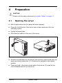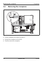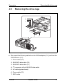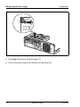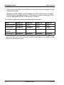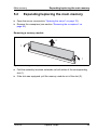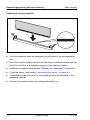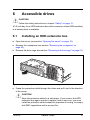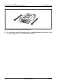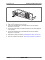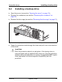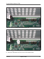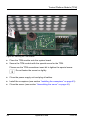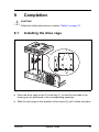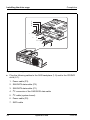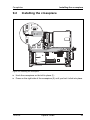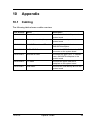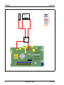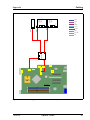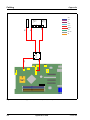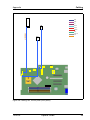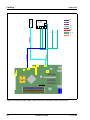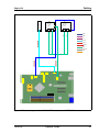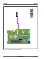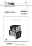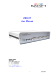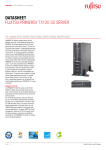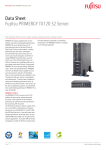
1
PRIMERGY TX120 S2 Server
Options Guide
Edition April 2009
Comments… Suggestions… Corrections…
The User Documentation Department would like to
know your opinion of this manual. Your feedback helps
us optimize our documentation to suit your individual
needs.
Feel free to send us your comments by e-mail to
[email protected].
Certified documentation
according to DIN EN ISO 9001:2000
To ensure a consistently high quality standard and
user-friendliness, this documentation was created to
meet the regulations of a quality management system
which complies with the requirements of the standard
DIN EN ISO 9001:2000.
cognitas. Gesellschaft für Technik-Dokumentation mbH
www.cognitas.de
Copyright and Trademarks
Copyright © 2009 Fujitsu Technology Solutions GmbH.
All rights are reserved.
Delivery subject to availability. The right to technical modification is reserved.
All hardware and software names used are trade names and/or trademarks of their respective
manufacturers.
Contents
1
Introduction . . . . . . . . . . . . . . . . . . . . . . . . . . . . 5
1.1
ENERGY STAR . . . . . . . . . . . . . . . . . . . . . . . . . . 6
1.2
Concept and target groups . . . . . . . . . . . . . . . . . . . 6
1.3
Documentation overview
1.4
Expansions and conversions . . . . . . . . . . . . . . . . . . 9
1.5
Notational conventions
2
Procedure . . . . . . . . . . . . . . . . . . . . . . . . . . . . 11
3
Safety . . . . . . . . . . . . . . . . . . . . . . . . . . . . . . 13
4
Preparation . . . . . . . . . . . . . . . . . . . . . . . . . . . 19
4.1
Opening the server . . . . . . . . . . . . . . . . . . . . . . . 19
4.2
Removing the crosspiece . . . . . . . . . . . . . . . . . . . 20
4.3
Removing the drive cage
5
Main memory . . . . . . . . . . . . . . . . . . . . . . . . . . 23
5.1
Equipping rules . . . . . . . . . . . . . . . . . . . . . . . . . 23
5.2
Expanding/replacing the main memory . . . . . . . . . . . . 25
6
Accessible drives
6.1
Installing an HDD extension box . . . . . . . . . . . . . . . 27
6.2
Installing a backup drive . . . . . . . . . . . . . . . . . . . . 31
7
Expansion cards in the PCI slots . . . . . . . . . . . . . . . 37
TX120 S2
. . . . . . . . . . . . . . . . . . . . 7
. . . . . . . . . . . . . . . . . . . . 10
. . . . . . . . . . . . . . . . . . . 21
. . . . . . . . . . . . . . . . . . . . . . . 27
Options Guide
Contents
7.1
PCI slot overview . . . . . . . . . . . . . . . . . . . . . . . . 37
7.2
Installing an expansion card . . . . . . . . . . . . . . . . . . 38
8
Trusted Platform Module (TPM) . . . . . . . . . . . . . . . . . 45
9
Completion . . . . . . . . . . . . . . . . . . . . . . . . . . . . 41
9.1
Installing the drive cage . . . . . . . . . . . . . . . . . . . . . 41
9.2
Installing the crosspiece . . . . . . . . . . . . . . . . . . . . 43
9.3
Assembling the server . . . . . . . . . . . . . . . . . . . . . 44
10
Appendix . . . . . . . . . . . . . . . . . . . . . . . . . . . . . 45
10.1
Cabling . . . . . . . . . . . . . . . . . . . . . . . . . . . . . . 45
Index
. . . . . . . . . . . . . . . . . . . . . . . . . . . . . . . . . . . . 53
Options Guide
TX120 S2
1
Introduction
The PRIMERGY TX120 S2 server is an Intel-based server for small and
medium-sized networks and can be used in the horizontal position or as a
desktop model.
The PRIMERGY TX120 S2 server features exceptionally low energy
consumption, very quiet running and a compact size. As a result, it is also the
ideal solution for home and small offices.
Thanks to its highly developed hardware and software components, the
PRIMERGY TX120 S2 server offers a high level of data security and availability.
These include hot-plug HDD modules, the ServerView server management
software, Prefailure Detection and Analysing (PDA) and Automatic Server
Reconfiguration and Restart (ASR&R).
Security functions in the BIOS-setup protect the data on the server against
manipulation. Additional security is provided by the lockable drive cover.
TX120 S2
Options Guide
5
ENERGY STAR
1.1
Introduction
ENERGY STAR
In some particular configurations1 the PRIMERGY TX120 S2 is
equipped with a power management system which, in energysaving mode, reduces the power consumption to <65 W. The
server thus satisfies the requirements of the U.S. Environmental
Protection Agency (EPA).
The EPA estimates that computer systems use around 5 % of all
electricity in the office sector and that this figure is growing
rapidly. If all computer systems and peripherals were placed in
energy-saving mode when not in use, the overall savings in
electricity could amount to some US $ 2 billion annually. These
savings would also prevent the emission of 20 million tons of
carbon dioxide into the atmosphere - equivalent to the emissions
from 5 million automobiles.
As an ENERGY STAR partner, Fujitsu Technology Solutions
GmbH has determined that in some particular configurations this
product meets the ENERGY STAR guidelines for energy
efficiency.
1
These servers are always delivered with a particular setting in the BIOS setup. For details
please see the manual “D2785 BIOS Setup Utility for PRIMERGY TX120 S2” on the
PRIMERGY ServerView Suite DVD 2.
1.2
Concept and target groups
This Options Guide shows you how to extend and upgrade your server.
V CAUTION!
The activities described in this manual may only be performed by
technical specialists.
I The installation and removal of the hot-plug components is described in
the Operating Manual supplied with the server.
6
Options Guide
TX120 S2
Introduction
1.3
Documentation overview
Documentation overview
More information on your PRIMERGY TX120 S2 can be found in the following
documents:
– “Quick Start Hardware - PRIMERGY TX120 S2” leaflet (only included as a
printed copy)
– “Quick Start Software - Quick Installation Guide” DVD booklet (only included
with the PRIMERGY ServerView Suite as a printed copy)
– “Safety notes and other important information” manual
– “Warranty” manual
– “PRIMERGY ServerView Suite Local Service Concept - LSC” manual
– “Returning used devices” manual
– “Helpdesk” leaflet
– Technical manual for the system board D2785
– “PRIMERGY TX120 S2 Server Operating Manual”
– “PRIMERGY TX120 S2 Server Options Guide”
– “D2785 BIOS Setup Utility für PRIMERGY TX120 S2“ manual
I Further information on SAS/SATA RAID controllers is provided in the
“Modular RAID Controller Installation Guide” (on PRIMERGY
ServerView Suite DVD 2 under Industry Standard Servers - Expansion Cards
- Storage Adapters - LSI RAID / SCSI Controllers).
Further information on other SAS/SATA RAID controllers (e.g. for
operating external SAS/SATA hard disk drives or tape drives) is available
on PRIMERGY ServerView Suite DVD 2 under Industry Standard Servers
- Expansion Cards - Storage Adapters - LSI RAID / SCSI Controllers.
TX120 S2
Options Guide
7
Documentation overview
Introduction
I PRIMERGY manuals are available in PDF format on the PRIMERGY
ServerView Suite DVD 2. The PRIMERGY ServerView Suite DVD 2 is
part of the PRIMERGY ServerView Suite supplied with every server.
If you no longer have the ServerView Suite DVDs, you can obtain the
relevant current versions using the order number U15000-C289.
The PDF files of the manuals can also be downloaded free of charge
from the Internet. The overview page showing the online documentation
available on the Internet can be found using the URL:
http://manuals.ts.fujitsu.com. The PRIMERGY server documentation can
be accessed using the Industry standard servers navigation option.
Further sources of information:
– PRIMERGY Abbreviations and Glossary on the PRIMERGY
ServerView Suite DVD 2
– Manual for the monitor
– Documentation for the boards and drives
– Operating system documentation
– Information files in your operating system
8
Options Guide
TX120 S2
Introduction
1.4
Expansions and conversions
Expansions and conversions
Main memory expansion
The system board supports up to 16 Gbyte of main memory. 4 slots (2 memory
banks with 2 slots each) are provided for the main memory. Each memory bank
can be equippeded with 1 GB, 2 GB or 4 GB unbuffered DDR2 memory
modules.
If the memory modules are installed in pairs, they must be identical (2-way interleaved mode).
Additional accessible drive
A 3.5-inch bay for an HDD extension box or a backup drive is available.
Expansion cards in the PCI slots
The following PCI slots are provided by the system board:
PCI slot
Description
1
PCI Express x8 slot
2
PCI Express x8 slot
3
PCI slot (32-bit/33MHz)
4
PCI Express x8 slot
TX120 S2
Options Guide
9
Notational conventions
1.5
Introduction
Notational conventions
The following notational conventions are used in this manual:
Text in italics
indicates commands or menu items.
“Quotation marks”
indicate names of chapters and terms that are being
emphasized.
Ê
describes activities that must be performed in the order
shown.
V CAUTION!
I
10
pay particular attention to texts marked with this symbol.
Failure to observe this warning may endanger your life,
destroy the system or lead to the loss of data.
indicates additional information, notes and tips.
Options Guide
TX120 S2
2
Procedure
V CAUTION!
●
The actions described in this manual should only be performed by
technical specialists.
●
Repairs to the device must only be carried out by service personnel.
Please note that unauthorized interference with the system will void
the warranty and exempt the manufacturer from all liability.
●
Any failure to observe the guidelines in this manual, and any improper
repairs could expose the user to risks (electric shock, energy
hazards, fire hazards) or damage the equipment.
Ê First of all, carefully read the safety instructions in the chapter “Safety” on
page 13.
Ê Make sure that all necessary manuals (see the section “Documentation
overview” on page 7) are available; print the PDF files if required. Most
importantly, you will need the operating manual for the server and the
technical manual for the system board.
Ê Shut the server down correctly, switch it off, disconnect the power plugs and
open the server as described in thechapter “Preparation” on page 19 .
Ê Carry out the expansion or upgrade of your server as described in the
pertinent chapter.
I Installation and removal of the hot-plug components are described in
the operating manual.
Ê Close the server, connect it to the power outlet, and switch it on as described
in the chapter “Completion” on page 41.
Ê Start the operating system and make the appropriate configuration if
necessary (see the operating manual).
TX120 S2
Options Guide
11
3
Safety
I The following safety instructions are also provided in the manual “Safety
notes and other important information”.
This device meets the relevant safety regulations for IT equipment. If you have
any questions about whether you can install the server in the intended
environment, please contact your sales outlet or our customer service team.
V CAUTION!
●
The actions described in this manual should only be performed by
technical specialists.
●
Repairs to the device that do not relate to CSS failures must only be
carried out by service personnel. Please note that unauthorized interference with the system will void the warranty and exempt the
manufacturer from all liability.
●
Any failure to observe the guidelines in this manual, and any improper
repairs could expose the user to risks (electric shock, energy
hazards, fire hazards) or damage the equipment.
TX120 S2
Options Guide
13
Safety
Before starting up
V CAUTION!
●
During installation and before operating the device, observe the
instructions on environmental conditions for your device.
●
If the device is brought in from a cold environment, condensation may
form both inside and on the outside of the device.
Wait until the device has acclimatized to room temperature and is
absolutely dry before starting it up. Material damage may be caused
to the device if this requirement is not observed.
●
Transport the device only in the original packaging or in packaging
that protects it from knocks and jolts.
Installation and operation
V CAUTION!
14
●
This unit should not be operated in ambient temperatures above
35 °C.
●
If the unit is integrated into an installation that draws power from an
industrial power supply network with an IEC309 connector, the power
supply's fuse protection must comply with the requirements for nonindustrial power supply networks for type A connectors.
●
The unit automatically adjusts itself to a mains voltage in a range of
100 V - 240 V. Ensure that the local mains voltage lies within these
limits.
●
This device must only be connected to properly grounded shockproof sockets or insulated sockets of the rack's internal power supply
with tested and approved power cables.
●
Ensure that the device is connected to a grounded shockproof socket
close to the device.
Options Guide
TX120 S2
Safety
V CAUTION!
●
Ensure that the power sockets on the device and the grounded
shockproof sockets are freely accessible.
●
The On/Off button or the main power switch (if present) does not
isolate the device from the mains power supply. To disconnect it
completely from the mains power supply, unplug all network power
plugs from the grounded shockproof sockets.
●
Always connect the server and the attached peripherals to the same
power circuit. Otherwise you run the risk of losing data if, for example,
the server is still running but a peripheral device (e.g. memory
subsystem) fails during a power outage.
●
Data cables must be adequately shielded.
●
The EN 50173 and EN 50174-1/2 standards apply for LAN cabling.
The minimum requirement is the use of a category 5 screened LAN
cable for 10/100 Mbit/s Ethernet, or a category 5e cable for Gigabit
Ethernet. The requirements from the ISO/IEC 11801 specification
must also be met.
●
Route the cables in such a way that they do not create a potential
hazard (make sure no-one can trip over them) and that they cannot
be damaged. When connecting the server, refer to the relevant
instructions in this manual.
●
Never connect or disconnect data transmission lines during a storm
(risk of lightning strike).
●
Make sure that no objects (e.g. jewelry, paperclips etc.) or liquids can
get inside the server (risk of electric shock, short circuit).
●
In emergencies (e.g. damaged casing, controls or cables, penetration
of liquids or foreign bodies), switch off the server immediately,
remove all power plugs and contact your sales outlet or customer
service team.
TX120 S2
Options Guide
15
Safety
V CAUTION!
●
Proper operation of the system (in accordance with IEC 60950-1/
EN 60950-1) is only ensured if the casing is completely assembled
and the rear covers for the installation slots have been fitted (electric
shock, cooling, fire protection, interference suppression).
●
Only install system expansions that satisfy the requirements and
rules governing safety and electromagnetic compatibility and those
relating to telecommunication terminals. If you install other expansions, they may damage the system or violate the safety regulations.
Information on which system expansions are approved for installation
can be obtained from our customer service center or your sales
outlet.
●
The components marked with a warning notice (e.g. lightning symbol)
may only be opened, removed or exchanged by authorized, qualified
personnel. Exception: CCS components can be replaced.
●
The warranty is void if the server is damaged during installation or
replacement of system expansions.
●
Only set screen resolutions and refresh rates that are specified in the
operating manual for the monitor. Otherwise, you may damage your
monitor. If you are in any doubt, contact your sales outlet or customer
service center.
Batteries
V CAUTION!
16
●
Incorrect replacement of batteries may result in a risk of explosion.
The batteries may only be replaced with identical batteries or with a
type recommended by the manufacturer (see the technical manual for
the system board).
●
Replace the lithium-battery on the system board in accordance with
the instructions in the technical manual for the system board.
Options Guide
TX120 S2
Safety
Working with CDs/DVDs and CD/DVD drives
When working with devices with CD/DVD drives, these instructions must be
followed.
V CAUTION!
●
Only use CDs/DVDs that are in perfect condition in your server's
CD/DVD drive, in order to prevent data loss, equipment damage and
injury.
●
Check each CD/DVD for damage, cracks, breakages etc. before
inserting it in the drive.
Note that any additional labels applied may change the mechanical
properties of a CD/DVD and cause imbalance.
Damaged and imbalanced CDs/DVDs can break at high drive speeds
(data loss).
Under certain circumstances, sharp CD/DVD fragments can pierce
the cover of the CD/DVD drive (equipment damage) and can fly out
of the device (danger of injury, particularly to uncovered body parts
such as the face or neck).
I You can prevent mechanical damage and damage to the CD/DVD drive,
as well as premature CD/DVD wear, by observing the following suggestions:
– Only insert CDs/DVDs in the drive when needed and remove them
after use.
– Store the CDs/DVDs in suitable sleeves.
– Protect the CDs/DVDs from exposure to heat and direct sunlight.
Laser information
The CD/DVD drive complies with IEC 60825-1 laser class 1.
V CAUTION!
The CD/DVD drive contains a light-emitting diode (LED), which under
certain circumstances produces a laser beam stronger than laser
class 1. Looking directly at this beam is dangerous.
Never remove parts of the CD/DVD drive casing!
TX120 S2
Options Guide
17
Safety
Modules with electrostatic-sensitive components
Systems and components that might be damaged by electrostatic discharge
(ESD) are marked with the following label:
Figure 1: ESD label
When you handle components fitted with ESDs, you must observe the following
points under all circumstances:
●
Remove the power plug before installing or removing components
containing ESDs.
●
You must always discharge yourself of static charges (e.g. by touching a
grounded object) before working.
●
The equipment and tools you use must be free of static charges.
●
Only touch the components at the positions highlighted in green (touch
points).
●
Do not touch any exposed pins or conductors on a component.
●
Use a grounding cable designed for this purpose to connect yourself to the
system unit as you install components.
●
Place all components on a static-safe base.
I You will find a detailed description for handling ESD components in the
relevant European or international standards (DIN EN 61340-5-1,
ANSI/ESD S20.20).
18
Options Guide
TX120 S2
4
Preparation
V CAUTION!
Please note the safety instructions in chapter “Safety” on page 13.
4.1
Opening the server
Ê Exit all applications and shut down the server properly.
Ê Press the On/Off button if the server has not been switched off by the
operating system.
Ê Unplug all power plugs.
Ê Disconnect all cables on the rear of the server.
3
1
2
Figure 2: Opening the server
Ê Remove the stabilizers from the server (see operating manual) and place the
server on its four rubber feet (1), if the server is operated in the vertical
position.
Ê Press and hold in the locks on both sides of the server (2), push the top
cover forwards and lift it up and off (3).
TX120 S2
Options Guide
19
Removing the crosspiece
4.2
Preparation
Removing the crosspiece
2
1
Figure 3: Removing the crosspiece
Ê Pull the crosspiece out a little to the side (1).
Ê Unhook the crosspiece on the left (2).
Ê Carefully remove the crosspiece.
20
Options Guide
TX120 S2
Preparation
4.3
Removing the drive cage
Removing the drive cage
1
2
3
4
5
6
7
Figure 4: Disconnecting the cables
Ê Disconnect the following cables from the SAS backplane (1-5) and from the
CD/DVD drive (6-7):
1. Power cable (P3)
2. SAS/SATA data cable (P2)
3. SAS/SATA data cable (P1)
4. I2C connector of the SAS/SATA data cable
5. I2C cable (system board)
6. Power cable (P5)
7. SATA cable
TX120 S2
Options Guide
21
Removing the drive cage
Preparation
1
2
Figure 5: Removing the drive cage
Ê Disengage the lock of the drive cage (1).
Ê Pull out the drive cage in the direction of the arrow (2).
22
Options Guide
TX120 S2
5
Main memory
V CAUTION!
Please note the safety instructions in chapter “Safety” on page 13.
The system board supports up to 16 GB of main memory. 4 slots (2 memory
banks with 2 slots each) are provided for the main memory. Each memory bank
can be equippeded with 1 GB, 2 GB or 4 GB unbuffered DDR2 memory
modules.
5.1
Equipping rules
2B
2A
1B
1A
Figure 6: Configuration of the main memory
TX120 S2
Options Guide
23
Equipping rules
Main memory
– If the memory modules are installed in pairs, they must be identical (2-way
interleaved mode).
– Memory module capacity may be different for the various pairs: e.g. pair
2A/2B may be equipped with two 1 GB memory modules, and pair 1A/1B
may be equipped with two 2 GB memory modules.
The following table shows the prescribed equipping order:
Mode
DIMM-1A
DIMM-2A
DIMM-1B
DIMM-2B
Single channel
equipped
empty
empty
empty
Dual channel
equipped
equipped
empty
eempty
Single/dual
channel1
equipped
equipped
equipped
empty
Dual channel
equipped
equipped
equipped
equipped
1
Dual channel mode is not activated unless the size of the memory module in DIMM 2-A is
equal to the sum of the memory modules in DIMM-1A and DIMM-1B (e.g.: DIMM-1A=1GB,
DIMM-1B=1GB, DIMM-2A=2GB)
24
Options Guide
TX120 S2
Main memory
5.2
Expanding/replacing the main memory
Expanding/replacing the main memory
Ê Open the server (see section “Opening the server” on page 19).
Ê Remove the crosspiece (see section “Removing the crosspiece” on
page 20).
Removing a memory module
2
1
1
Figure 7: Removing a memory module
Ê Fold the assembly brackets outwards on both sides of the corresponding
slot (1).
Ê If the slot was equipped: pull the memory module out of the slot (2).
TX120 S2
Options Guide
25
Expanding/replacing the main memory
Main memory
Installing a memory module
Figure 8: Installing a memory module
Ê Fold the assembly brackets outwards on both sides of the corresponding
slot.
Ê Insert the memory module into the slot with the connecting contacts and the
notch first until the side brackets engage on the memory module.
Ê Install the crosspiece (see section “Installing the crosspiece” on page 43).
Ê Close the server (see section “Assembling the server” on page 44).
Ê If necessary, place the server in the vertical position as described in the
operating manual
Ê Connect the system to the line voltage and switch it on.
26
Options Guide
TX120 S2
6
Accessible drives
V CAUTION!
Follow the safety instructions in chapter “Safety” on page 13.
A 3.5-inch bay for an HDD extension box (with a maximum of two HDD modules)
or a backup drive is available.
6.1
Installing an HDD extension box
Ê Open the server (see section “Opening the server” on page 19).
Ê Remove the crosspiece (see section “Removing the crosspiece” on
page 20).
Ê Remove the drive cage (see section “Removing the drive cage” on page 21).
Figure 9: Removing the protection shield from the 3.5-inch bay
Ê Grasp the protection shield through the holes and pull it out in the direction
of the arrow.
V CAUTION!
Store the protection shield in a safe place. If you remove the HDD
extension box again and don't replace it with a new one, you must
install the protection shield instead for purposes of cooling, to comply
with EMC regulations and to prevent fire.
TX120 S2
Options Guide
27
Installing an HDD extension box
Accessible drives
Figure 10: Fixing the rails on the HDD extension box
Ê Fix the rails to the HDD extension box by inserting the pins on the rail in the
corresponding holes in the HDD extension box.
28
Options Guide
TX120 S2
Accessible drives
Installing an HDD extension box
Figure 11: Installing an HDD extension box
Ê Slide the HDD extension box into the slot.
Ê Connect the SAS data cable to the HDD extension box (see cabling
diagrams in the appendix).
Ê Connect the power cable to the HDD extension box (see cabling diagrams
in the appendix).
Ê Connect the SAS LED cable to the HDD extension box (see cabling
diagrams in the appendix).
Ê Install the drive cage (see section “Installing the drive cage” on page 41).
Ê Install the crosspiece (see section “Installing the crosspiece” on page 43).
TX120 S2
Options Guide
29
Installing an HDD extension box
Accessible drives
Figure 12: Removing the dummy cover from the top cover
Ê Press the dummy cover outwards from the top cover in the direction of the
arrow.
V CAUTION!
Keep the dummy cover in a safe place. If the HDD extension box is
removed again and not replaced with a new one, then the dummy
cover must be reinstalled due to cooling, the applicable EMC regulations (regulations on electromagnetic compatibility) and fire
protection.
Ê Close the server (see section “Assembling the server” on page 44).
Ê If necessary, place the server in the vertical position as described in the
operating manual
Ê Connect the system to the line voltage and switch it on.
30
Options Guide
TX120 S2
Accessible drives
6.2
Installing a backup drive
Installing a backup drive
Ê Open the server (see section “Opening the server” on page 19).
Ê Remove the crosspiece (see section “Removing the crosspiece” on
page 20).
Ê Remove the drive cage (see section “Removing the drive cage” on page 21).
Figure 13: Removing the protection shield from the 3.5-inch bay
Ê Grasp the protection shield through the holes and pull it out in the direction
of the arrow.
V CAUTION!
Store the protection shield in a safe place. If the backup drive is
removed again and not replaced with a new one, then the protection
shield must be reinstalled due to cooling, the applicable EMC regulations (regulations on electromagnetic compatibility) and fire
protection.
TX120 S2
Options Guide
31
Installing a backup drive
Accessible drives
Figure 14: Fixing the rails on the backup drive
Ê Fix the rails on the backup drive by inserting the pins on the rails in the corresponding holes in the backup drive.
Figure 15: Installing a backup drive
Ê Insert the backup drive into the location.
32
Options Guide
TX120 S2
Accessible drives
Installing a backup drive
1
2
Figure 16: Connecting the USB and power cables to a DAT drive
2
1
Figure 17: Connecting the USB and power cables to a RDX drive
Ê Plug the USB cable (1) and the power cable (2) into the backup drive (see
cabling diagrams in the appendix).
Ê Plug the other end of the USB cable into the system board (see cabling
diagrams in the appendix).
Ê Install the drive cage (see section “Installing the drive cage” on page 41).
Ê Install the crosspiece (see section “Installing the crosspiece” on page 43).
TX120 S2
Options Guide
33
Installing a backup drive
Accessible drives
Figure 18: Removing the dummy cover from the top cover
Ê Press the dummy cover outwards from the top cover in the direction of the
arrow.
V CAUTION!
Keep the dummy cover in a safe place. If the backup drive is removed
again and not replaced with a new one, then the dummy cover must
be reinstalled due to cooling, the applicable EMC regulations (regulations on electromagnetic compatibility) and fire protection.
Ê Close the server (see section “Assembling the server” on page 44).
Ê If necessary, place the server in the vertical position as described in the
operating manual
Ê Connect the system to the line voltage and switch it on.
34
Options Guide
TX120 S2
7
Expansion cards in the PCI slots
V CAUTION!
Follow the safety instructions in chapter “Safety” on page 13.
7.1
PCI slot overview
4
3
2
1
Figure 19: PCI slots
PCI slot
Description
1
PCI Express x8 slot
2
PCI Express x8 slot
3
PCI slot (32-bit/33MHz)
4
PCI Express x8 slot
TX120 S2
Options Guide
37
Installing an expansion card
7.2
Expansion cards in the PCI slots
Installing an expansion card
I Slots 1-3 are provided for optional expansion cards; slot 4 can be used
exclusively for the optional SAS RAID controller.
Slots 1-3
Ê Open the server (see section “Opening the server” on page 19).
Ê Please read the documentation supplied with the expansion card.
1
2
1
3
Figure 20: Opening the lock and removing the slot cover
Ê Press the lock together (1) and open it up (2).
Ê Pull out the slot cover (3).
38
Options Guide
TX120 S2
Expansion cards in the PCI slots
Installing an expansion card
V CAUTION!
Keep the slot cover in a safe place. If the expansion card is removed
and not replaced with a new card, the slot cover must be reinstalled
due to cooling, to comply with applicable EMC regulations (regulations on electromagnetic compatibility) and to protect against fire.
Figure 21: Installing an expansion card
Ê Push the expansion card as far as it will go into the slot on the system board.
Ê Press the expansion card into the slot until you feel it click into place.
Ê Close the lock again until it engages.
Ê If necessary, connect the cable to the expansion card and the other components.
Ê Close the server (see section “Assembling the server” on page 44).
Ê If necessary, place the server in the vertical position as described in the
operating manual
Ê Connect the system to the line voltage and switch it on.
TX120 S2
Options Guide
39
Installing an expansion card
Expansion cards in the PCI slots
PCI-Steckplatz 4: SAS-RAID-Controller einbauen
Ê Open the server (see section “Opening the server” on page 19).
Ê Please read the documentation supplied with the SAS RAID controller.
4
2
1
1
3
Figure 22: Opening the lock and removing the slot cover
Ê Press the lock together (1) and open it up (2).
Ê Remove the slot screw (3).
Ê Pull out the slot cover (4).
40
Options Guide
TX120 S2
Expansion cards in the PCI slots
Installing an expansion card
Figure 23: Fastening the slot cover to the SAS RAID controller
Ê Screw the slot cover to the SAS RAID controller.
TX120 S2
Options Guide
41
Installing an expansion card
Expansion cards in the PCI slots
MLC1
MLC2
1
2
Figure 24: Connecting the SAS/SATA cable and inserting the SAS RAID controller
Ê Connect the SAS/SATA cable to the SAS RAID controller (MLC1 port).
Ê Insert the SAS RAID controller into slot 4.
42
Options Guide
TX120 S2
Expansion cards in the PCI slots
Installing an expansion card
2
1
Figure 25: Closing the lock and fastening the SAS RAID controller
Ê Fasten the SAS RAID controller in place using the slot screw (1).
Ê Close the lock again until it engages (2).
TX120 S2
Options Guide
43
8
Trusted Platform Module (TPM)
Contents of the TPM installation kit
1
2
3
4
Figure 26: Contents of the TPM installation kit
1
TPM module
3
Special screw for TPM
2
TPM spacer
4
TPM screwdriver insert bit for
TPM special screw
Installing a TPM module
V CAUTION!
Please note the safety instructions in chapter “Safety” on page 13.
Ê Open the server (see chapter “Preparation” on page 19).
Ê Remove the crosspiece (see section “Removing the crosspiece” on
page 20).
TX120 S2
Options Guide
45
Trusted Platform Module (TPM)
1
2
Figure 27: Pivoting the power supply unit
Ê Unplug all cables on the power supply unit.
Ê Pivot the power supply unit (1) in the direction of the arrow in order to access
the cut-out on the system board intended for the TPM (2).
46
Options Guide
TX120 S2
Trusted Platform Module (TPM)
Figure 28: Cut-out on the system board intended for the TPM
Figure 29: Inserting the TPM spacer
Ê Insert the TPM spacer into the cut-out on the system board.
TX120 S2
Options Guide
47
Trusted Platform Module (TPM)
Figure 30: Securing the TPM module
Ê Place the TPM module onto the system board.
Ê Secure the TPM module with the special screw for the TPM.
Please use the TPM screwdriver insert bit to tighten the special screw.
I Do not fasten the screw too tightly.
Ê Close the power supply unit and plug all cables.
Ê Install the crosspiece (see section “Installing the crosspiece” on page 43).
Ê Close the server (see section “Assembling the server” on page 44).
48
Options Guide
TX120 S2
9
Completion
V CAUTION!
Follow the safety instructions in chapter “Safety” on page 13.
9.1
Installing the drive cage
a
1
2
a
Figure 31: Installing the drive cage
Ê Place the drive cage on the 3.5-inch bay (1), so that the four tabs in the
housing (a) are positioned in the corresponding openings.
Ê Slide the drive cage in the direction of the arrow (2) until it clicks into place.
TX120 S2
Options Guide
41
Installing the drive cage
Completion
1
2
3
4
5
6
7
Figure 32: Connecting the cables
Ê Plug the following cables to the SAS backplane (1-5) and to the CD/DVD
drive (6-7):
1. Power cable (P3)
2. SAS/SATA data cable (P2)
3. SAS/SATA data cable (P1)
4. I2C connector of the SAS/SATA data cable
5. I2C cable (system board)
6. Power cable (P5)
7. SATA cable
42
Options Guide
TX120 S2
Completion
9.2
Installing the crosspiece
Installing the crosspiece
1
2
Figure 33: Installing the crosspiece
Ê Hook the crosspiece on the left in place (1).
Ê Press on the right side of the crosspiece (2) until you feel it click into place.
TX120 S2
Options Guide
43
Assembling the server
9.3
Completion
Assembling the server
Figure 34: Assembling the server
Ê Place the top cover flat and straight on the server and push it as far as it will
go in the direction of the arrow.
Make sure that the locks on both sides of the server engage.
44
Options Guide
TX120 S2
10
Appendix
10.1
Cabling
The following table shows a cable overview:
Code Number
Name
Description
A3C40102407
Front LAN cable
connects the frotsite LAN port to the
system board
A3C40102408
Control panel cable (front panel) connects the control panel to the
system board
A3C40102412
SAS/SATA backlane LED cable
conntects the upper to the lower
SAS/SATA backplane
A3C40102413
SATA CD/DVD cable
connects the CD/DVD drive to the SATA
connector on the system board
A3C40102415
SAS/SATA cable
conntects the upper (and - if installed lower) SAS/SATA backplane to the
system board
A3C40102416
I2C cable
connects the upper SAS/SATA
backplane to the system board
A3C40102417
USB cable
connects the USB backup drive to the
system board
TX120 S2
Options Guide
45
FA N 2
S YS
AT X P S U /4 P IN
S ATA ML C 1
AT X P S U / 24 P IN
Upper
B P L L ED
46
FA N 1 S YS
U S B D AT
FR ON TP A NE L
<- P1
<- P7
PS U E528 -V 50
P2 ->
P3 ->
P5 ->
CN6
CN7
P o rt2
P o rt1
U PPER
SA S
BPL
(to p )
optic
alal Driv
o p tic
D ri ve e
Cabling
Appendix
USB
Data
I2C
Power
SATA
Adapter
SAS
ATA 100
IDE
Figure 35: Power cable: Upper SAS/SATA backplane and CD/DVD drive
Options Guide
TX120 S2
S ATA
S26 36 1- D 27 85
FA N 2
S YS
AT X P S U /4 P IN
S ATA ML C 1
AT X P S U / 24 P IN
Upper
B P L L ED
TX120 S2
FA N 1 S YS
U S B D AT
FR ON TP A NE L
<- P1
<- P7
PS U E528 -V 50
P2 ->
P3 ->
P5 ->
CN6
Options Guide
B P L L ED
P o rt4
P o rt3
X6
CN7
P o rt2
P o rt1
LOW ER
SA S
BPL
U PPER
SA S
BPL
(to p )
optic
alal Driv
o p tic
D ri ve e
Appendix
Cabling
USB
Data
I2C
Power
SATA
Adapter
SAS
ATA 100
IDE
Figure 36: Power cable: Uppper and lower SAS/SATA backplane and CD/DVD drive
47
S ATA
S26 36 1- D 27 85
FA N 2
S YS
AT X P S U /4 P IN
S ATA ML C 1
AT X P S U / 24 P IN
Upper
B P L L ED
48
FA N 1 S YS
U S B D AT
FR ON TP A NE L
<- P1
<- P7
PS U E528 -V 50
P2 ->
P3 ->
P5 ->
CN6
CN7
P o rt2
P o rt1
USB
TA PE
or RDX
U PPER
SA S
BPL
(to p )
optic
alal Driv
o p tic
D ri ve e
Cabling
Appendix
Options Guide
USB
Data
I2C
Power
SATA
Adapter
SAS
ATA 100
IDE
Figure 37: Power cable: Upper SAS/SATA backplane, backup drive and CD/DVD drive
TX120 S2
S ATA
S26 36 1- D 27 85
Appendix
Cabling
Frontpanel
Data
USB
I2C
SY S1
FA N
SATA
Power
Adapter
SAS
A 3C 40102408
ATA 100
SY S2
FA N
IDE
U S B D AT
FA N 1 S YS
Upper
B P L L ED
FA N 2
S YS
S ATA ML C 1
AT X P S U /4 P IN
FR ON TP A NE L
AT X P S U / 24 P IN
S ATA
S26 36 1- D 27 85
Figure 38: Cabling: fan, control panel (front panel)
TX120 S2
Options Guide
49
FA N 2
S YS
AT X P S U /4 P IN
S ATA ML C 1
AT X P S U / 24 P IN
Upper
B P L L ED
50
FA N 1 S YS
U S B D AT
FR ON TP A NE L
A 3C 40102415
A 3C 40102416
A 3C 40102413
Options Guide
4
3
2
1
CN3
P o rt2
P o rt1
CN1
CN7
U PPER
SA S
BPL
optic
alal Driv
o p tic
D ri ve e
(to p )
(top)
Cabling
Appendix
USB
Data
I2C
Power
SATA
Adapter
SAS
ATA 100
IDE
Figure 39: Data and signal cable: Upper SAS/SATA backplane and CD/DVD drive
TX120 S2
S ATA
S26 36 1- D 27 85
FA N 2
S YS
AT X P S U /4 P IN
S ATA ML C 1
AT X P S U / 24 P IN
Upper
B P L L ED
TX120 S2
FA N 1 S YS
U S B D AT
FR ON TP A NE L
A 3C 40102415
A 3C 40102416
A 3C 40102413
Options Guide
4
3
2
1
CN2
P o rt4
P o rt3
CN1
CN3
P o rt2
P o rt1
CN1
CN2
A 3C 40102412
LOW ER
SA TA /SA S
BPL
CN7
U PPER
SA TA /SA S
BPL
optic
alal Driv
o p tic
D ri ve e
(to p )
(top)
Appendix
Cabling
USB
Data
I2C
Power
SATA
Adapter
SAS
ATA 100
IDE
Figure 40: Data and signal cable: 2*SAS/SATA backplane and CD/DVD drive
51
S ATA
S26 36 1- D 27 85
Cabling
Appendix
Data
USB
I2C
TA PE
o p ticor
al DR
ri veDX
(to p )
(Option)
SATA
Power
Adapter
SAS
ATA 100
A 3C 40102417
IDE
U S B D AT
FA N 1 S YS
Upper
B P L L ED
FA N 2
S YS
S ATA ML C 1
AT X P S U /4 P IN
FR ON TP A NE L
AT X P S U / 24 P IN
S ATA
S26 36 1- D 27 85
Figure 41: USB cable for additional backup drive
52
Options Guide
TX120 S2
Index
3.5-inch slot
I
information, additional 8
installing an HDD extension box
27
A
accessible drives
9, 27
L
laser information 17
light emitting diode (LED)
lithium battery 16
B
backup drive
fixing rails 28, 32
installing 31
C
cabling
data and signal cables 50, 51, 52
fan, intursion switch, front
panel 49
power cable 46, 47, 48
components
hardware 5
software 5
configuration, main memory 23
crosspiece
installing 43
removing 20
D
data manipulation 5
drive cage
installing 41
removing 21
dummy cover
removing 30, 34
saving 30, 34
N
notational conventions
17
10
10
P
PCI expansion card, installing
PCI slots, overview 37
protection shield
removing 27, 31
saving 27, 31
38
R
RAID controller
installing 40
E
ENERGY STAR 6
equipping rules, main memory 24
ESD (devices sensitive to electrostatic
discharge) 18
expansion card 9
expansion card, installing 38
TX120 S2
M
main memory 9, 23
configuration 23
equipping rules 24
expanding 25
replacing 25
meaning of the symbols
memory module
installing 26
removing 25
27
S
SAS RAID controller
installing 40
security function 5
server
assembling 44
opening 19
slot cover
Options Guide
53
Index
removing 38
saving 39
T
target group 6
top cover
fitting 44
removing 19
TPM module
installing 45
scope of delivery 45
Trusted Platform Module 45
54
Options Guide
TX120 S2