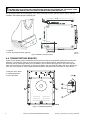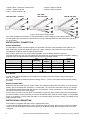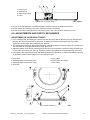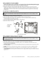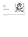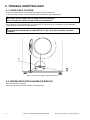
1
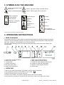
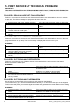
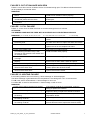
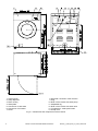
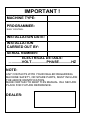
PROFESSIONAL WASHER EXTRACTORS
6kg
7,5kg
SOAP HOPPER ON FRONT PANEL
INSTALLATION, MAINTENANCE AND USER'S MANUAL
502207 K
Publication date: 18 Aug 2009
USER'S MANUAL
1. TABLE OF CONTENTS
1. TABLE OF CONTENTS ................................................................................................ 1
2. WARNINGS AND LABELS ........................................................................................... 2
2.1. INSTRUCTIONS FOR MAINTENANCE, ADJUSTMENT AND SAFETY OF PEOPLE .........................3
3. SYMBOLS ON THE MACHINE ..................................................................................... 4
4. OPERATION INSTRUCTIONS...................................................................................... 4
5. FIRST SERVICE AT TECHNICAL PROBLEM.............................................................. 6
502207_K_PUB_DATE_18_AUG_2009.DOC
USER'S MANUAL
1
2. WARNINGS AND LABELS
TO MINIMIZE THE RISK OF FIRE, INJURY BY ELECTRIC SHOCK OR SERIOUS INJURIES TO PEOPLE
OR PROPERTY DAMAGE, PLEASE READ AND FOLLOW THE FOLLOWING INSTRUCTIONS:
– This English version is original language version. Without this original version, these instructions are incomplete.
– Before installation, operation and maintenance of the machine read carefully the complete instructions,
i.e. this „Installation, maintenance and user's manual“, „Programming manual“ and „Spare parts manual“.
The Programming manual and Spare parts manual are not delivered with a machine by default. You shall
ask the supplier / manufacturer to obtain Programming manual and Spare parts manual.
– Follow the instruction written in manuals and keep the manuals in a proper place by the machine for later use.
– Do not bypass the safety instructions stated in the manual and warnings on the machine labels.
– The machine is destined for a textile washing only. It is not allowed to wash objects which are not made
of textile; these could damage the glass, rubber seals etc. and can cause damage or injuries.
– Follow all valid basic safety rules and laws.
– This machine must not be operated by children. Before starting and operating the machine make sure
there are not any persons (children) or animals in the machine or in machine vicinity.
– Do not operate the machine with broken / missing parts, opened covers, also do not operate a machine
which was not installed and put in operation according to instructions stated in the „Installation manual“.
– Do not tamper with the machine controls.
– Do not touch the door glass before the washing cycle has been finished.
Do not open the door before the drum rotation stops and water is drained off the drum!
Do not open the soap hopper during the water filling!
– Do not use cleaning aids which are destined for dry cleaning and substances damaging machine rubber seals.
Do not use any flammable or explosive materials. Do not store any flammable materials near the machine.
– The warranty of the machine cannot be accepted in case corrosion was caused by chlorine and chlorine
compounds impact.
– Keep the machine surface clean and free of flammable materials.
– Under certain conditions, hydrogen gas may be created in the hot water system that has not been used
for two or more weeks. Hydrogen gas is explosive. If the hot water system has not been used for such
period open all hot water taps and let the water run out for few minutes. This will release any accumulated
gas. As this gas is flammable, do not smoke or use open flames during this time.
– During extracting, the machine produces an equivalent noise level which does not exceed the value of 70 dB (A).
– Be informed about the location of the laundry main switch or other emergency electrical disconnection devices.
– The electrical parts are still under tension even if the „ON/OFF“ switch is off. Take out the mains plug.
The machine is only out of tension if the mains plug is taken out!
Ö WASHING AND CLEANING DETERGENTS
Always read carefully and follow the instructions for fabric, washing and cleaning substances from manufacturers.
Heed all warnings. Store these materials out of the reach of children. Observe all warnings stated on containers
and covers to avoide possible injuries and the linen or machine damage.
We recommend to use only proper washing soaps (with reduced foaming). Do not overdose the soap amount
indicated on its cover. Overdosing of washing soaps will cause an excesive foaming wich can have negative
effects to washing and also can damage the machine.
! WARNING!
IF THE INSTALLED APPLIANCE OPERATE WITH COIN, TOKEN OR SIMILAR OPERATION FOR USE
IN SELF-SERVICE SITUATIONS, THEN THE OWNER-INSTALLER MUST PROVIDE A REMOTE-LOCATED
EMERGENCY STOP DEVICE. THIS DEVICE MUST BE PLACED IN SUCH A WAY THAT IT IS EASY
AND SAFELY ACCESSIBLE FOR THE USERS. THE EMERGENCY STOP DEVICE TAKES CARE
THAT AT LEAST THE CONTROL CIRCUIT OF THE APPLIANCE IS INTERRUPTED.
! WARNING!
DO NOT TOUCH THE DOORGLASS UNTIL CYCLE HAS BEEN COMPLETED. DO NOT OPEN DOOR
UNTIL CYLINDER REMAINS STOPPED AND WATER HAS BEEN DRAINED FROM CYLINDER.
DO NOT PUT ARTICLES SOILED WITH EXPLOSIF SOLVENTS AND/OR DANGEROUS CHEMICAL
PRODUCTS IN THE MACHINE. THIS MACHINE SHOULD NOT BE USED BY CHILDREN.
DO NOT LET CHILDREN PLAY IN, ON, OR AROUND THE MACHINE. BEFORE TURNING THE MACHINE
„ON“, MAKE SURE THAT THERE ARE NO PEOPLE OR ANIMALS PRESENT IN OR AROUND THE MACHINE.
2
USER'S MANUAL
502207_K_PUB_DATE_18_AUG_2009.DOC
WARNING!
Always disconnect the washer from the electrical supply before attempting any service. The washer
extractor is out of tension if the main plug is taken out or when the main supply is disconnected.
When the main switch is turned off the inlet terminals of the machine main switch are still under current!
! WARNING!
ORIGINAL OR IDENTICAL PARTS MUST BE USED FOR REPLACEMENT IN THIS MACHINE.
AFTER SERVICING REPLACE AND SECURE ALL PANELS IN THE ORIGINAL WAY. TAKE THESE MEASURES
FOR CONTINUED PROTECTION AGAINST ELECTRICAL SHOCK, INJURY, FIRE AND/OR PROPERTY DAMAGE.
! WARNING!
LOOKING AT THE MACHINE FROM THE FRONT VIEW THE DRUM ROTATION DURING EXTRACTION
MUST BE CLOCKWISE.
2.1. INSTRUCTIONS FOR MAINTENANCE, ADJUSTMENT AND SAFETY
OF PEOPLE
Some important information for the usage of the machine are not (or only partly) mentioned in this User´s Manual.
Missing information is possible to find in Installation and Maintenance Manual, which is delivered with the machine.
References to „Installation and Maintenance Manual“ according to norm EN ISO 10472-1:
1. Description of the safe work system when maintenance is performed
/ adjustment / and when eliminating defects
– chapter 5 / 5 / 6
2. Description of qualities for ventilation
– chapter 4
3. Procedures on searching for defects / cleaning / maintenance
– chapter 6 / 5 / 5
4. Heat risks
– chapter 3
5. Safety procedure on manipulation, installation and dismantling
– chapter 4
References to „Installation and Maintenance Manual“ according to norm EN ISO 10472-2:
1. Maintenance of door blocking
– chapter 5
2. Electric risks
– chapter 2
3. Heat energy
– chapter 3
4. Sight holes
– chapter 3
5. Explosive atmosphere
– chapter 2
6. Biological or chemical pollution of water
– chapter 2
7. Maximal possible overspeed
– chapter 3
502207_K_PUB_DATE_18_AUG_2009.DOC
USER'S MANUAL
3
3. SYMBOLS ON THE MACHINE
Danger, read and follow written
instructions
Caution, high power voltage, electrical devices
Caution, increased temperature
Caution, outlet of steam from the machine
Caution, dangerous
electrical tension,
electric devices
Program selection
Prewash
Remaining
time of
a program
Main wash
Switching on a program
or allow advance *
Rinse
Temperature of
washing *
Spinning
Opening the door
End of program,
you can take off the linen
* Note: according to setting in programming mode
4. OPERATION INSTRUCTIONS
Ö PRIOR TO WASHING
The manufacturer bears no responsibility for textiles being damaged by improper washing technologies.
The linen has to be assorted according to its type and a selected wash temperature. Empty all pockets;
nails, pins, screws etc. could damage the linen and the machine.
To achieve better washing results, mix large and small pieces and put the linen into the washer free
and separated.
1. „Program/run“ mode push button
2. Switch of the machine
3. „F“ push button
4. „START“ push button
5. Door open push button
6. Label of wash programms
7. Wash program steps indicators
8. Wash program number indicator
9. Indicator of wash program remaining time
10. Indicator of wash bath temperature
11. Button for wash program selection
12. Soap hopper
Ö OPERATING:
1. Switch on the machine by a switch (2) located on the left of the control panel
2. The programming switch (1) must stand into „Run-mode“:
3. Open the machine door by the push button (5).
4. Put linen in the washer. The machine capacity of linen must not be exceeded.
5. Close the door by pushing on the left side of the door till you hear a click. Watch your hands!
4
USER'S MANUAL
502207_K_PUB_DATE_18_AUG_2009.DOC
6. Choose a program by the push button (11) according to the degree of dirt and character of linen. Find the
kind of progam on program label (6).
7. Pull out the soap hopper (12) and fill up the dispencer chambers according to the selected program:
st
– I chamber with a washing powder for prewash.
nd
– II chamber with a washing powder/liquid soap for main wash.
rd
– III chamber with a fabric softener or starch (liquid soap).
Do not open the soap hopper during the water filling !
8. Press the START button (4). The cycle indicators (7) show the current wash step.
– the first digital line (8) shows number of program
– the second digital line (9) shows the resting wash time
– the third digital line (10) shows the washing temperature
Before you push the „START“ button (4) there is a possibility to select the following functions by pressing
the „F“ button (3):
PREWASH, SOAK, DELAY TIME, ECONOMIC, NO SPIN, GENTLE WASHG, (see Programming manual
„Easy Control“).
Note: For locking a program mode, changing factory settings and possibilities of program changes
and setup - see Programming manual.
9. When the door LED lights up you can open the door using the push button (5).
10. Remove the linen from the drum after finishing wash program.
Ö WASHING PROGRAMS:
502207_K_PUB_DATE_18_AUG_2009.DOC
USER'S MANUAL
5
5. FIRST SERVICE AT TECHNICAL PROBLEM
IMPORTANT!
TECHNICAL INTERVENTION ON THE WASHING MACHINE IS ONLY FOR QUALIFIED TECHNICIANS
WITH SUFFICIENT TECHNICAL KNOWLEDGE OF THE „EASY CONTROL“ WASHING MACHINE.
FAILURE 1: DRAIN FAILURE NOT FINAL SEQUENCE
Failure 1 occurs when the electronic timer detects that the water is not drained after 3 minutes in a drain
or spin step. The failure message is displayed at the end of the cycle.
DIAGNOSE:
1. Check the drain tube of the washing machine.
2. Check the drain valve.
3. Check the wiring:
verify if the drain valve is not energised
The drain valve is normal open.
4. Check the pump (only machines without door
handle).
If the drain tube is blocked: repair the drain tube.
If the drain valve is defective: replace the drain
valve.
If the wiring is damaged: repair the wiring.
If the pump is broken : repair or replace the pump.
FAILURE 2: DRAIN FAILURE FINAL SEQUENCE
Failure 2 occurs when the electronic timer detects that the water is not drained after 3 minutes in the last
programmed drain or spin step. The failure message is displayed at the end of the cycle.
DIAGNOSE:
1. Check the drain tube of the washing machine
2. Check the drain valve.
3. Check the wiring:
verify if the drain valve is not energized
The drain valve is normal open.
4. Check the pump (only machines without door
handle).
If the drain tube is blocked: repair the drain tube.
If the drain valve is defective: replace the drain
valve.
If the wiring is damaged: repair the wiring.
If the pump is broken : repair or replace the pump.
FAILURE 3: OUT OF BALANCE BEFORE SPIN
Failure 3 occurs when the out of balance sensor is activated before the spin sequence has started.
Result: the machine will not spin.
DIAGNOSE:
1. Check if the out of balance switch is broken
2. Check the position of the out of balance
switch
3. Check the wiring:
the contact of the out of balance switch is
normally closed
If the out of balance switch is broken: replace the out
of balance switch
If the out of balance switch is not correctly mounted:
install the out of balance switch properly
If there is no continuity: repair the wiring
FAILURE 4: OUT OF BALANCE NORMAL SPIN
Out of balance at normal Spin will occur when a wash machine is bad loaded.
The machine will try up to 10 times to redistribute the laundry in the drum before the spin step is skipped.
This functions will protect your machine against overload and guarantees the normal lifetime of the washing
machine.
DIAGNOSE:
1. Check the position of the out of balance
switch.
2. If this failure occurs often.
3. Check the wiring if there is no bad connection.
The out of balance sensor is a NC contact
6
USER'S MANUAL
If the out of balance switch is not correctly mounted,
install the out of balance switch properly
Use a fully loaded drum. A completely filled drum produce
less unbalance than a drum that is only filled for 1/3.
If there is a bad connection: repair the wiring
502207_K_PUB_DATE_18_AUG_2009.DOC
FAILURE 5: OUT OF BALANCE HIGH SPIN
Failure 5 occurs when the out of balance sensor is activated at high spin. This failure indicates that there
will be probably a mechanical defect.
DIAGNOSE:
1. Check the position of the out of balance
switch.
2. Check the springs and the other
mechanical parts that fix the drum.
3. Check the wiring if there is a bad
connection.
If the out of balance switch is not correctly mounted,
install the out of balance switch properly.
If you see a broken mechanical part: replace the
broken part.
If there is a bad connection: repair the wiring.
FAILURE 11: FILL FAILURE
Failure 11 occurs when the water level has not reached its target level in X minutes.
ATTENTION:
THE RUBBER HOSE MUST BE FIXED WITH A FASTENER ON THE ELECTRONIC SENSOR.
DIAGNOSE: (X = 10‘ for R6, R7, R10, F6, F7, F10
X = 15‘ for R16, R22, F13, F16, F22, F23
1. Check if the external water valves are open.
2. Check if the water inlet valves are not
blocked by dust.
3. Check the coil of the water inlet valves.
4. Check the drain valve.
5. Check if the rubber hose
(for measuring the water level) is well
mounted on the electronic level sensor and
on the drain valve.
6. Check if the hose on the electronic sensor
is air tight.
7. Check if the hose doesn’t contain water
(siphon).
8. Check the continuity of the wiring.
9. Check the output relay that powers inlet
valves and the drain valve.
10. Check the output relay that powers inlet
valves and the drain valve.
X = 20‘ for R35)
If the water valves are closed: open the water inlet
valves.
If the water inlet valves are blocked by dust: clean
the water inlet valves or replace the water inlet valves
If the coil of the water inlet valve is broken:
replace the coil or the complete inlet valve.
If the drain valve is defective: replace the drain valve.
If the hose is not well mounted:
install the rubber hose properly.
If the air tube is not air tight: replace the air tube.
If the air tube contains water: remove the water and
fix the hose so that it doesn’t work as a siphon.
If the wiring is not continue: repair the wiring.
If the relay receives a command signal but is not
closed, replace the electronic board.
If the relay does not receives a command signal,
replace the electronic board.
FAILURE 13: HEATING FAILURE
If the heating resistors are not functioning : failure message 13 will be displayed.
The failure message is generated when the temperature is not raising with 3°C in 10 minutes time.
For HE = on: wait for heat selected => fault message 13 can occur
For HE = oFF: no wait for heat selected => fault message 13 will not occur
DIAGNOSE:
1. Check if the heating contactor is activated.
2. Check if the heating resistors are heating
3. Check if the temperature sensor is
functioning
4. Check the output relay that powers
the heating contactor
5. Check the output relay that powers
the heating contactor
502207_K_PUB_DATE_18_AUG_2009.DOC
If the heating contactor is not activated: repair the
wiring or replace the contactor
If the heating resistors are not heating:
Repair the wiring or replace the defective resistors
If the temperature sensor is defective: replace the
temperature sensor
If the relay is broken, replace the electronic board
If the relay is not broken, but doesn’t receive a signal
from the electronic board, replace the electronic board
USER'S MANUAL
7
FAILURE 14: HEATING TIME FAILURE
When after 75 minutes the target temperature is not reached (for a machine set as wait for heat):
Message 14 will be displayed.
DIAGNOSE:
1. Check if the heating resistors are heating
2. Check the water temperature
3. Check if the temperature sensor is
functioning
If the heating resistors are not heating:
Repair the wiring or replace the defective resistors
If the hot water temperature is too low: increase the
temperature of the hot water
If the temperature sensor is defective : replace the
temperature sensor
FAILURE 16: COIN BLOCKING 1
When the input for coin drop 1 is blocked for more then 5 seconds: message 16 will be displayed.
Case EP = ON.
Fault 16 will be displayed if the external start release signal is high for more then 10 seconds when the door
has been opened at the end of the program.
DIAGNOSE:
1. Check the well functioning of coin drop 1.
2. Check the continuity of the wiring.
If the coin drop micro contact or optocoupler is not
functioning 100%: replace the coin drop.
If the wiring is not continue : repair the wiring.
FAILURE 17: COIN BLOCKING 2
When the input for coin drop 1 is blocked for more then 5 seconds: message 17 will be displayed.
DIAGNOSE:
1. Check the well functioning of coin drop 2.
2. Check the continuity of the wiring.
If the coin drop micro contact or optocoupler is not
functioning 100%: replace the coin drop.
If the wiring is not continue: repair the wiring.
FAILURE 99: SAFETY ERROR
When Error 99 occurs this is a main error message to prevent that the door can be opened.
On the lower display instead of Err, the temperature value is displayed.
Causes :
* If at the end of the wash cycle :
- if there is still water in the tub, it’s not allowed to open the door.
- if the temperature in the tub is too hot (water ?), it’s not allowed to open the door.
If the problem disappears also Error 99 will disappear and the door can be opened.
* If there is a problem with the door lock system during the wash-spin cycle :
- the wash-spin cycle is interrupted at once and the machine will keep the door locked.
- Error 99 can only be removed by manual intervention (keyswitch in setup mode and pressing the
SET button). As a result a new error number that corresponds with the door lock problem will be
displayed. The door will only be unlocked after manual intervention.
ATTENTION!
!
BEFORE EACH INTERVENTION WAIT UNTIL THE TEMERATURE HAS REACHED A SAFE VALUE!
DIAGNOSE:
Check the Diagnoses like for error messages 2, 6, 7 or please contact the your supplier for more technical
assistance.
FAILURE 6-10 / 12 / 15 / 18-90 / 100-180
Please contact the your supplier for more technical assistance
8
USER'S MANUAL
502207_K_PUB_DATE_18_AUG_2009.DOC
INSTALLATION AND MAINTENANCE MANUAL
1. TABLE OF CONTENS
1. TABLE OF CONTENS .................................................................................................. 1
2. IMPORTANT SAFETY INSTRUCTIONS....................................................................... 2
2.1. DURING TRANSPORTATION AND STORAGE..................................................................................3
2.2. MACHINE SYMBOLS .........................................................................................................................3
3. TECHNICAL SPECIFICATIONS ................................................................................... 4
3.1. TECHNICAL INFORMATION..............................................................................................................4
4. MACHINE INSTALLATION ........................................................................................... 7
4.1. MANIPULATION AND UNPACKING...................................................................................................7
4.2. SPACE REQUIREMENTS ..................................................................................................................7
4.3. FASTENING THE MACHINE ..............................................................................................................7
4.4. TRANSPORTING BRACES................................................................................................................8
4.5. CONNECTION ...................................................................................................................................9
4.6. PREPARING THE MACHINE FOR OPERATION..............................................................................11
4.7. CONNECTION OF EXTERNAL COIN METER BOX .........................................................................11
5. MAINTENANCE AND ADJUSTMENTS...................................................................... 12
5.1. MAINTENANCE................................................................................................................................12
5.2. ADJUSTMENTS AND PART´S EXCHANGES ..................................................................................13
6. TROUBLE SHOOTING AIDS ...................................................................................... 16
6.1. DOOR FAILS TO OPEN ...................................................................................................................16
6.2. ERROR INDICATION SHOWN ON DISPLAY ...................................................................................16
7. LIST OF RECOMMENDED SPARE PARTS ............................................................... 17
8. PUTTING THE MACHINE OUT OF SERVICE ............................................................ 18
8.1. DISCONNECTING THE MACHINE...................................................................................................18
8.2. MACHINE DISPOSAL ......................................................................................................................18
502207_K_PUB_DATE_18_AUG_2009.DOC
INSTALLATION AND MAINTENANCE MANUAL
1
2. IMPORTANT SAFETY INSTRUCTIONS
WARNING - SAVE THESE INSTRUCTIONS FOR LATER USE.
Failure to comply with the instructions may lead to incorrect use of the appliance, and may
result in risk of fire, bodily injuries or death and/or damage to the laundry and/or the appliance.
WARNING - read the IMPORTANT SAFETY INSTRUCTIONS in this manual carefully before
operating the appliance. improper use of the appliance may cause risk of fire, electrical
shock or serious body injuries or death as well as serious damage to the appliance.
– This English version is the original version. Without this version, the instructions are incomplete.
– Before installation, operation and maintenance of the machine read carefully the complete instructions, i.e.
this „Installation, maintenance and user's manual“, „Programming manual“ and „Spare parts manual“.
The Programming manual and Spare parts manual are not delivered with a machine by default. You shall
ask the supplier / manufacturer to obtain Programming manual and Spare parts manual.
– Follow the instruction written in manuals and keep the manuals in a proper place by the machine for later use.
– Safety instructions included in manuals for personnel operating the washing machine must be printed and posted
on a visible place near the machine in the laundry room.
– If any problems or failures occur which you do not understand, immediately contact your dealer, serviceman
or manufacturer.
– Follow all basic and valid safety instructions and laws. Do not bypass the instructions stated in the instruction manual,
and warnings on the labels. The labels must stay on the machine and they must be legible.
– The machine must be connected to the power, ground, water, ventilation and steam supply according to
the installation manual, in compliance with the local standards done by qualified technicians with proper
authorization. The valid standards for connecting to the local power network (TT / TN / IT, ...) must be followed.
In the standard execution, the washer may not be suitable for connecting to an IT supply system.
– If you have a machine with frequency inverter do not change the parameters of the inverter. Doing so can
cause serious injury, fire, machine damage, etc.
– The washer extractor is intended to be permanently connected to fixed wiring.
– Any changes concerning the installation which are not described in this Installation Manual, must be
approved by the supplier or manufacturer. Otherwise, the supplier and manufacturer are not responsible
for potential injuries to operators or for any damages. Interventions into the machine execution or
functions are not allowed, and the manufacturer refuses any responsibility in such cases.
– Define the dangerous areas in the laundry room and obstruct an admission to them during machine's operating.
– Operation of the machine with malfunctions, missing parts or open covers is not allowed.
– Do not tamper with the machine's control.
– Do not store flammable materials around the machine.
– Keep the top of the machine clean, with out the presence of flammable materials. Do not wash or spray
the machine with running water.
– It is possible that there are residues of products used during the production proces in the new washer.
These residues could cause stains on your laundry. Therefore, you must first run at least 1 hot wash
with old rags before using for your normal laundry.
– Once a three months check the proper function of ground and stop button.
– The stop device is omitted on machines design for coin, token, external payment system or similar
operation for use
in self-service situation. The owner-installer-user must provide a remote-located emergency stop device that is
connected to each machine.
– Disconnect the power supply to the machine before doing any interventions to the machine.
– When the „O / I“ switch is in the position off „O“, the electrical parts are still under tension. Pull out the plug
from power supply network. The machine is without tension only when the plug is out of the socket !
– Do not repair or adjust belt drive when the machine is in operation, plug out the plug for repair or maintenance.
Do not repair or replace any part of the washer, or attempt any servicing unless specifically recommended
in the maintenance instructions. All other servicing should be referred to a qualified service person.
– The instructions and warnings described in this manual do not include all conditions and situations which
may occur during the installation, maintain or operate of your machine. They must be generally understood.
Caution and care are factors which are not included in the design of this machine and all persons who install,
operate or maintain the machine must be qualified and familiar with the operating instructions.
! WARNING!
LOOKING AT THE MACHINE FROM THE FRONT VIEW THE DRUM ROTATION DURING EXTRACTION
MUST BE CLOCKWISE.
Installation and service can be done only by a service organization with proper authorization from the manufacturer.
2
INSTALLATION AND MAINTENANCE MANUAL
502207_K_PUB_DATE_18_AUG_2009.DOC
2.1. DURING TRANSPORTATION AND STORAGE
DURING TRANSPORTATION AND STORAGE NEVER PUSH, PULL OR EXERT PRESSURE ON COMPONENTS
PROTRUDING FROM THE CONTOUR LINE OF THE MACHINE (CONTROL ELEMENTS, DOOR LOCKS
ETC.). MAKE SURE THAT THESE PARTS ARE SECURED TO AVOID ANY DAMAGE DURING MANIPULATION
AND INSTALLATION.
If transportation is provided by the customer it is necessary to follow the manufacturer´s instructions concerning
transportation, handling and storage. In this case the manufacturer is not responsible for any damage of machine
during transportation.
The ambient temperature for transportation and storage must be between -5°C and +55°C. Relative humidity
must be between 30 % and 90% without condensation. When stored in a free area the machine must be protected
against mechanical damage and weather condition effects.
2.2. MACHINE SYMBOLS
See User's manual.
502207_K_PUB_DATE_18_AUG_2009.DOC
INSTALLATION AND MAINTENANCE MANUAL
3
3. TECHNICAL SPECIFICATIONS
3.1. TECHNICAL INFORMATION
DIMENSIONS
DRY LOAD CAPACITY (1/10)
6 kg / 15 lb
PACKING DIMENSIONS:
width
depth
height
transportation capacity
MACHINE DIMENSIONS:
width
depth
height
DIMENSIONS OF INNER DRUM:
diameter
depth
drum capacity
Diameter of loading opening:
*
7,5 kg / 18 lb
710 mm / 27,95"
740 mm / 29,13"
1060 mm / 41,73“
3
3
0,557 m / 19,67 ft
710 mm / 27,95"
740 mm / 29,13"
1060 mm / 41,73“
3
3
0,557 m / 19,67 ft
685 mm / 26,96“
645 mm / 25,39“
940 mm / 37“
685 mm / 26,96“
685 mm / 26,96“
940 mm / 37“
530 mm / 21“
530 mm / 21“
330 mm / 13“
270 mm / 10,6“
3
3
73 dm / 19,3 gal
60 dm / 15.8 gal
284 mm / 11.2“
WEIGHT
net
gross
160 kg / 353 lb
165 kg / 364 lb
165 kg / 364 lb
175 kg / 386 lb
MACHINE EXECUTION
Frame, cabinet, external and internal drum materials:
Programmer:
stainless steel
electronic
ELETRICAL DATA
Electrical system of the machine:
1x220-240V 50/60Hz - applicable for 6 kg / 15 lb,
electrical heating < 3kW
1x220-240V 50/60Hz - applicable for 7,5 kg / 18 lb,
electrical heating 2750W, hot water
1x220-240V 50/60Hz - not applicable for electrical
heating
3x220-240V 50/60Hz - applicable for electrical heating
>= 3kW
3x380-415V+N 50/60Hz - applicable for electrical
heating >= 3kW
1x380-440V 50/60Hz - not applicable for electrical
heating
3x380-440V 50/60Hz - applicable for electrical heating
>= 3kW
1x200-208V 50/60Hz - not applicable for electrical
heating
3x200-208V 50/60Hz - applicable for electrical heating
>= 3kW
Permitted deviation of voltage:
Permitted deviation of frequency:
TOTAL INPUT OF THE MACHINE WITH:
electric heating 2750 W
electric heating 6000 W
electric heating 9000 W
without heating
INPUT PROTECTION FOR ONE MACHINE:
electric heating 2750 W
electric heating 6000 W
electric heating 9000 W
without heating
Nominal output of motor:
from -6% to +10% V
±1% Hz
1x220-240V
16A
10A
3.5 kW
6.5 kW
9.5 kW
0.5 kW
3x220-240V 3x380-415V+N
20A
16A
32A
20A
10A
10A
426 W
440V
16A
10A
Tab.3.1.
4
INSTALLATION AND MAINTENANCE MANUAL
502207_K_PUB_DATE_18_AUG_2009.DOC
WASHING FUNCTIONS
DEFAULT RPM OF THE DRUM:
washing
high extracting
G - factor of spinning:
Number of wash programs:
48 RPM
1150 RPM
390
1100 RPM
360
1 - 15
HEATING
Types of heating:
cold soft / hot soft water
- without electric heating
cold soft / additional hot soft water
- with electric heating 2750 W
- with electric heating 6000 W
- with electric heating 9000 W
CONNECTION
WATER CONNECTION:
water pressure
water inlet
maximal water temperature
CONNECTION OF WATER DRAINAGE:
via drain valve diameter
flow amount with drain valve
via drain pump, hose diameter
flow amount with drain pump
Soap Dispenser:
0.1 – 0.8 MPa / 1-8bar / 14.5 - 116 PSI
3/4“
70°C / 158°F
51 mm / 2“
3
-1
-1
52 dm min / 14 gal min
33.5 mm / 1.32“
3
-1
-1
36 dm min / 9.5 gal min
Front soap dispenser with 3 compartments
CONSUMPTION
AVERAGE WATER CONSUMPTION WITHOUT PREWASH:
wash bath temperature 60°C, normal low level at main
wash, normal high level at rinse
AVERAGE WATER CONSUMPTION WITH PREWASH:
wash bath temperature (35°C - prewash, 60°C - main wash),
normal low level for prewash and main wash, normal high
level for rinse
AVERAGE ELECTRICAL POWER CONSUMPTION
WITHOUT PREWASH:
wash bath temperature 60°C
106,3 l
118,7 l
128,7 l
144,3 l
100% electric heating
100% electric heating
2,14 kWh
2,15 kWh
2,58 kWh
2,60 kWh
AVERAGE ELECTRICAL POWER CONSUMPTION
WITH PREWASH:
wash bath temperature (35°C - prewash, 60°C - main wash)
WORKING CONDITIONS
ambient temperature
relative humidity
height above sea level
from + 5 ° C (41°F) to + 35 °C (95°F)
30 % ÷ 90 % without condensation
up to 1000 m / 3280 ft
ANCHORING
ANCHORING THE MACHINE:
max. static loading of floor (with linen and water)
max. dynamic loading of floor
((alternative stress at extracting)
frequency of dynamic loading
free locating - in horizontal level
184 kg / 405 lbs
198 kg / 437 lbs
± kg
Hz
± kg
Hz
NOISE
MEAN NOISE LEVEL AT MAX. LOADING:
*
70 dB (A)
maximum dimensions including protruding parts
Tab.3.1. continue
502207_K_PUB_DATE_18_AUG_2009.DOC
INSTALLATION AND MAINTENANCE MANUAL
5
1. Control panel
2. Soap dispenser
3. Drum venting
4. Serial plate
5. Connection of cold water
6. Connection of hot water
7. Fuses
6
8. Electrical connection of the machine
9. Plug
10. Drain of the version with drain pump
11. Adjustable leg
12. Drain of the version with drain valve
13. „Program/run“ mode push button
14. Pump cover
Fig. 3.1. Dimensions and components of the machine
INSTALLATION AND MAINTENANCE MANUAL
502207_K_PUB_DATE_18_AUG_2009.DOC
4. MACHINE INSTALLATION
4.1. MANIPULATION AND UNPACKING
DURING TRANSPORTATION
All doors and passages the machine is to be transported through during installation must be reasonably
dimensioned to meet the width, height and depth off the machine including the package. The machine
dimensions are stated in chapter „3.Technical information“.
UNPACKING
If possible, leave the machine in transporting package until the machine connection in the laundry.
The machine is screwed to the skid by two bolts M10x60, fig.4.1., pos.1. The placement of the bolts M10x60,
fig.4.1., pos.1 depends on machine model - (according to position of the transformer on the rear beam
of the frame). Remove the packaging and remove the rear panel, see fig.4.4. Remove the bolts M10x60,
fig.4.1., pos.1, by which the machine is screwed to the skid. Remove the plate of packaging fig.4.1., pos.2
by unscrewing the adjustable leg together with the nut M10. Mount the rear panel and the adjustable leg
together with the nut M10 back to the machine.
1. Bolt M10x60
2. Plate of packaging
Fig.4.1.Section view from the top of the machine
ACCESSORIES DELIVERED WITH THE MACHINE
After unpaking check if all accessories have been delivered according to your order.
4.2. SPACE REQUIREMENTS
WORKING CONDITIONS OF THE MACHINE
The washer must not be installed or stored in an area where it will be exposed to water and/or weather.
Avoid damp conditions where water or moisture could run down the walls and covers of the washer or cover
the floor around the washer. Do not install the washer above an open gutter. Close any nearby gutters so
that waste water steam cannot collect near/inside the washer.
REQUIRED ROOM DIMENSIONS
Provided that the requirements in respect to room dimensions are not met, the maintenance of the fixed or
inbuilted machine may be difficult.
Leave at least a 0.6 m / 2 ft free space between the rear panel of machine and the wall. Leave at least a
0.04m / 1.57“ free space between the side panel of the machine and the wall or other machine.
4.3. FASTENING THE MACHINE
The machine is too be located on a leveled floor which complies to static and dynamic stress of the
machine. Check the position of machine top by a water level and adjust machine legs (fig.3.1., pos.20).
502207_K_PUB_DATE_18_AUG_2009.DOC
INSTALLATION AND MAINTENANCE MANUAL
7
!
WARNING !
IF THE MACHINE IS LOCATED ON A HIGHER BASE FOR BETTER OPERATION, THE FRONT LEGS
OF THE MACHINE SHOULD BE LOOCKED FOR SAFETY REASONS (SEE FIG. 4.3.).
Do not forget to leave an access space to the lever of emergency door opening (fig.4.3.,pos.2), which is
located in the bottom left front machine part.
1. U-profile
2. Lever of emergency door opening
Fig.4.3. Bottom machine frame
4.4. TRANSPORTING BRACES
There are two striking colour transporting braces which must be removed before putting the machine into
operation. Unscrew four bolts (1) on the rear panel of the washing machine. Dismantle the rear cover.
Unscrew nuts (3) fastening braces (2) to the washing unit on the left and right up on high of the tub axis.
Take out the braces (2). Screw bolts (1) with nuts (3) back to the rear panel after brace removing. Braces (2)
store out of a machine for cause of later possible transport. Mount the rear cover back on the machine.
1. Bolt joint of the brace
2. Transporting brace
3. Nut of the brace
Fig.4.4. Transporting braces
8
INSTALLATION AND MAINTENANCE MANUAL
502207_K_PUB_DATE_18_AUG_2009.DOC
4.5. CONNECTION
ELECTRICAL CONNECTION
!
WARNING !
THE MACHINE MUST BE CONNECTED TO THE POWER, GROUND, WATER, VENTILATION AND STEAM
SUPPLY ACCORDING TO THE INSTALLATION MANUAL, IN COMPLIANCE WITH THE LOCAL STANDARDS
DONE BY QUALIFIED TECHNICIANS WITH PROPER AUTHORIZATION. THE VALID STANDARDS FOR
CONNECTING TO THE LOCAL POWER NETWORK (TT / TN / IT, ...) MUST BE FOLLOWED. IN THE STANDARD
EXECUTION, THE WASHER MAY NOT BE SUITABLE FOR CONNECTING TO AN IT SUPPLY SYSTEM.
! WARNING !
THE MACHINE MUST BE CONNECTED TO THE VOLTAGE SUPPLY THROUHT THE MAIN SWITCH
WHICH IS A PART OF ELECTRIC INSTALLATION IN THE PLACE OF THE MACHINE INSTALLATION.
THIS MAIN SWITCH MUST BE EASILY ACCESSIBLE FOR THE MACHINE OPERATOR.
! WARNING !
THE WASHER EXTRACTOR IS INTENDED TO BE PERMANENTLY CONNECTED TO THE ELECTRICAL
SUPPLY.
ALL MACHINES TYPES ARE PRODUCED ACCORDING THE EMC-DIRECTIVE (ELECTRO-MAGNETICCOMPATIBILITY). THEY CAN BE USED IN RESTRICTED SURROUNDINGS ONLY (COMPLY MINIMALLY
WITH CLASS A REQUIREMENTS). FOR SAFETY REASONS THERE MUST BE KEPT THE NECESSARY
PRECAUTION DISTANCES WITH SENSITIVE ELECTRICAL OR ELECTRONIC DEVICE(S).
The machines have been designed for connecting to the electrical network according to the specifications
of your order. Before connection check if the electrical values stated on the serial plate of the machine
correspond to your electrical network. If not do not connect the machine, please contact your dealer.
If the machine is not equipped with a supply disconnecting device, like a main switch then a supply disconnecting
device need to be provided in the installation for all electrical supplies connected to the machine, in accordance
with EN 60204-1 standard, point 5.3. This device shall disconnect the electrical equipment of the machine
from the supply when required e.g. maintenance.
EMERGENCY STOP DEVICE
The machines are equipped with an stop device in accordance with ISO13850 - category 0 stop function.
Nevertheless, the stop device is omitted on machines design for coin, token, external payment system
or similar operation for use in self-service situation. The owner-installer-user must provide remote-located
emergency stop device(s). This emergency stop device(s) needs to stop each machine in accordance
with ISO13850 - category 0. There are made provisions in the wiring harness, were immediate removal of power
to the actuators can be accomplished. See the electrical schematic of the machine for correct connection
of the device.
Supply cable protection against short-circuit or overloading must be executed with circuit breakers and fuses
in the laundry switchboard. Look for an adequate value of the circuit breaker in technical information.
ELECTRIC HEATING:
EXECUTION:
9000 W
6000 W
2750 W
1AC 220-240 V
3AC+N 380-415 V
3AC 220-240 V
3AC 440 V
4 x C16, 2.5 mm2
3 x C32, 4 mm2
3 x C16, 2.5 mm2
-
2 x C16, 2.5 mm2
4 x C16, 2.5 mm2
3 x C20, 4 mm2
-
-
without electrial
heating
2 x C10, 2.5 mm2
2 x C10, 2.5 mm2
Tab.4.5.A The values of securing and minimal wire section recommended by the manufacturer
Connect the delivered cable conductors (marked in fig.4.5) to the plug ! The plug must fulfil the local
standards and regulations.Connection of voltage and grounding must comply to the local regulations.
You can use the original delivered cable only. Do not exchange the cable for another cable than the original
one supplied by the manufacturer.
502207_K_PUB_DATE_18_AUG_2009.DOC
INSTALLATION AND MAINTENANCE MANUAL
9
4. Black - phase conductor
5. Black - phase conductor
1. Green-yellow - protection conductor PE
2. Brown - phase conductor
3. Blue - neutral conductor N
3AC 440V
3AC 220-240V
1AC 220-240V / 50/60Hz
3AC+N 380-415V
Fig.4.5. Connection of input cables
If the cable is attached from above, it is recommended to make a sagging on the cable in front of its entry
into the cable bush. In this way an ingress of the running condensed water into the bush and/or machine
can be avoided.
WATER SUPPLY CONNECTION
WATER HARDNESS
It is advisable to contact the water supplier for information concerning the properties of the water in your
area. Good wash results are dependent also on the water hardness. For medium to very hard water,
consideration should be made to make the water softer.
Only in some cases is the use of hard water desirable, such as adding softener in the linen.
The soap supplier can help you with making the right decisions concerning hard water, soft water, washing
programs, type of soap and other related items to have the best wash results.
dH fH gr/gal
Characteristics
mmol / dm3
England
Germany
France
USA
soft
0 - 1,25
0 - 7°
0 - 12°
0 - 8,75°
0-3
medium
hard
1,25 - 2,5
2,5 - 3,75
7 - 14°
14 - 21°
12 - 25°
25 - 37°
8,75 - 17,5°
17,5 - 26,3°
3-7
7 - 15
very hard
above 3,75
above 21°
above 37°
above 26,3°
above 15
Tab.4.5. B
HOT WATER
The hot water supply temperature connected to the hot water inlet of the machine may not be higher
then 70°C - 158°F.
We advice a minimal hot water temperature setting of 60°C - 140°F if the machine has an electric heating
of 2750W.
WATER CONNECTION
Most machines are made with 2 or 3 water inlets. One is always marked with „soft water“. If more inlets are
present, they are marked with „Hot water“ or „Hard water“. For connection dimensions see fig. 3.2. Always
use the flexible hose delivered with the machine, if not present, contact your dealer. In each case do not
use a fixed connection to the water supply.
For the proper function of the machine, it is necessary to keep the water pressure within the limits stated in
the technical data. It is also necessary to connect all available water inlets to a water supply. If a hard water
supply is not present, connect it with soft water. If no hot water supply is present, contact your dealer for the
proper required action.
WATER DRAIN CONNECTION
The machine is equipped with drain valve or optional with pump.
– for the machine equipped with drain valve; connect the drain pipe to the drain valve by means of included
clamp. The main drain pipe must have the capacity to be able to handle the total output of all connected
machines.
10
INSTALLATION AND MAINTENANCE MANUAL
502207_K_PUB_DATE_18_AUG_2009.DOC
– for the machine equipped with drain pump; connect the end of the drain hose to a siphon or via a wash basin / sink. The hose must be laid out without kinks. The end of the hose must be not higher than
100 cm / 39“ above floor level.
AIR VENT CONNECTION
The machine has rectangular opening in the hopper front panel (fig. 3.1.,pos. 3). Never cover this opening.
4.6. PREPARING THE MACHINE FOR OPERATION
CHECKING BEFORE PUTTING INTO SERVICE
1. Make sure the transporting braces are removed.
2. Put out all things from wash drum.
3. Check the machine horizontal position.
4. Check connection and clearance of your drain, channel or central drainage.
5. Check earthing and electrical supply connection.
6. Open water valves to machine and check hose and connections for leaks.
7. Read carefully the „User´s manual“.
8. Put the electrical plug into the wall socket.
4.7. CONNECTION OF EXTERNAL COIN METER BOX
4.7.1. CONNECTING COIN METER TO THE WASHING MACHINE
!
WARNING !
DISCONNECT POWER SUPPLY IN ELECTRICAL BOX OF A LAUNDRY OR TAKE OUT THE MAIN
PLUG FROM A WALL SOCKET !
! WARNING !
THE MACHINE MUST BE CONNECTED TO THE POWER, GROUND, WATER, VENTILATION AND STEAM
SUPPLY ACCORDING TO THE INSTALLATION MANUAL, IN COMPLIANCE WITH THE LOCAL STANDARDS
DONE BY QUALIFIED TECHNICIANS WITH PROPER AUTHORIZATION. THE VALID STANDARDS FOR
CONNECTING TO THE LOCAL POWER NETWORK (TT / TN / IT, ...) MUST BE FOLLOWED. IN THE STANDARD
EXECUTION, THE WASHER MAY NOT BE SUITABLE FOR CONNECTING TO AN IT SUPPLY SYSTEM.
1. Connect a Normal Open contact of the external coin box to the timer input by a connection cable (see
electrical scheme). A connection is performed to the programming switch on the machine rear panel by
connector. Remove top cover of the machine by loosening of 2 screws from rear side, pick up rear part of
a cover and drag it forward. Draw out the signal cable of coin meter box trought a swivel on rear panel
into the machine.
2. Connectors 6,3 mm are connected to free clamps of the programming switch (clamp No.2 and 5) on the
rear panel. Connect the brown wire to the green wire (outer coin meter input) and the black wire to the
red wire (+ 12V).
3. Connect outer coin meter to the power supply 230A AC 50/60 Hz. For this connection use connecting
cable, which is part of equipment. Connect the cable wires to the plug! The plug connection must be in
accordance with local regulations. The power supply connection and earthing must be in accordance with
local regulations. Use only original delivered cable! Do not use other cable which is not delivered with the
product!
4. Supply wires in the machine must be fixed properly to the machine by straps and these wires must lead
out of springs, belt and pulley !
5. Select coin option „on“ in configuration menu of machine timer according instruction of programming
manual.
502207_K_PUB_DATE_18_AUG_2009.DOC
INSTALLATION AND MAINTENANCE MANUAL
11
5. MAINTENANCE AND ADJUSTMENTS
!
WARNING !
ALWAYS FOLLOW SAFETY INSTRUCTIONS! DO NOT BYPASS ANY SAFETY DEVICES OR THEIR
PARTS. ANY INTERFERENCE TO THE MACHINE FUNCTIONS AND CONSTRUCTION ARE PROHIBITED!
USE THE PROPER CHEMICAL AGENTS WHICH AVOID CALCIUM SEDIMENTS ON HEATING ELEMENTS
AND OTHER MACHINE PARTS. DISCUSS THIS ISSUE WITH YOUR SUPPLIER OF WASHING PRODUCTS.
THE MANUFACTURER OF THE MACHINE IS NOT RESPONSIBLE FOR THE DAMAGE OF HEATING
ELEMENTS AND OTHER MACHINE PARTS DUE TO CALCIUM SEDIMENTS.
DO NOT OPERATE THE MACHINE WITH BROKEN / MISSING PARTS OR OPENED COVERS!
BEFORE MAINTENANCE WORK DISCONNECT THE MACHINE POWER SUPPLY!
WHEN THE MAIN SWITCH IS TURNED OFF THE INLET TERMINALS OF THE MACHINE MAIN SWITCH
ARE STILL UNDER CURRENT!
THAT IS THE WAY TO AVOID INJURIES.
In case of serious failures call the technical service of your supplier.
5.1. MAINTENANCE
DAILY CHECKING AND MAINTENANCE
1. Check that no linen or other parts (paperclips...) are left lying in the drum or in the rubber door seal, to
avoid damage to rubber or appearance of rust.
2. Clean the door seal from any remaining detergent and other foreign matter.
3. Clean the top and body when water or detergent traces are on the machine. Use a damped cloth, do not
use abrasive cleaners. Dry with a soft cloth.
4. At the end of working day remove all sediments of washing soap from the soap-hopper drawers. Pull it out
as far as the stop and then take it right out with a sharp tug. To ensure efficient operation, the washing
powder compartments and siphon should be cleaned under hot running water. Take out the siphon and
push a needle through the opening. Clean the nozzles above the dispenser drawer with a brush. Then
remove soap sediments between plastic body of soap hopper and aluminium label.
5. At the end of the working day, open the machine door to allow airing out the machine.
CHECKING AND MAINTENANCE EVERY SIX MONTHS
! WARNING !
MACHINE PROTECTIVE CONNECTION AND EARTHING MUST BE CHECKED EVERY 6 MONTHS!
1. The filters in the water connection at the valves need to be cleaned. Turn off the tap. Unscrew the hoses
at the back of the appliance. Take out the filter at the centre with pointed pliers, clean and re-insert.
When re-attaching the hoses, make sure that the seals are seated correctly. Check water inlets for leaks.
Tighten the connections or replace the seals of the inlet hose if necessary.
2. On machines with electric heating check the tightening of the contacts of heating elements terminals and
other power terminals (main switch, fuse disconnectors, contactors).
3. Check:
– for the machine equipped with drain valve; that the drain valve is not leaking during the wash process
and that it opens properly afterwards (drain valve opens when electrical power falls off).
– for the machine equipped with drain pump; check that the pump gives its normal flow rate during
draining. The drain pump only needs to be cleaned if it has become blocked with foreign bodies (buttons,
paper clips...). Before this, any remaining water must be drained off.
! WARNING !
HOT MACHINE PARTS SHOULD BE ALLOWED TO COOL FIRST!
First disconnect the appliance from the mains by taking off the plug. Turning the bolt (2) counter clockwise
open the pump cover (3). Turn the pump cover (1) until the water starts leaking out of the pump and capture
it. Then unsrew the pump cover (1) completely and take out all strange subjects. After cleaning, screw the pump
cover (1) back. Dry the water which might remain on the pump cover (3) and shut the cover. Secure the
cover (3) by turning the bolt (2) clockwise to the utmost position.
12
INSTALLATION AND MAINTENANCE MANUAL
502207_K_PUB_DATE_18_AUG_2009.DOC
1. Pump cover
2. Security bolt
3. Open pump cover
4. Latch
Fig. 5.1. Drain pump
4. Check for the belt tightness or possible damage; therefore remove the machine rear cover.
5. Check visually all hoses and connection inside the machine for leaking.
6. Check the condition and tightness of bolt joints (fig.5.2.C,pos.7 and 8) which hold the trunnion.
5.2. ADJUSTMENTS AND PART´S EXCHANGES
ADJUSTMENT OF DOOR SEAL THRUST
1. For increasing (resp. decreasing) the pressure of the door seal, take off spacers (3) (resp. add spacers)
between the door frame and the hinge blocks. Therefore remove the screws (6) on the door frame.
Tighten the screws again after positioning the spacers.
2. The adjustments of the door seal pressure must be executed as follows. The door rubber (4) must still touch
the tub rubber at the hinge side when the door opens at 5°.
3. Adjust the position of the door by loosening the screws (6) on the door frame. The door hook (1) must be right
in the center of the door lock opening. Tighten the screws (6) again after correct positioning of the door.
4. If necessary, take of spacers (2) (resp. add spacers) between the door latch (1) and the door frame to achieve
a good door pressure and a normal force for closing the door.
1. Door hook
2. Adjusting spacers of the door latch
3. Adjusting spacers of the door hinge
4. Door seal
5. Door glass
6. Bolts of the door hinge
7. Door frame
Fig.5.2. Door fastening
502207_K_PUB_DATE_18_AUG_2009.DOC
INSTALLATION AND MAINTENANCE MANUAL
13
REPLACEMENT OF DOOR RUBBER
1. Open the door. Remove the door glass (fig.5.2., pos.5) with rubber (4) from the stainless steel door (7) by
pushing it towards the drum. Do it carefully, not to damage the glass. Remove the seal (4) from the glass.
2. Place a new rubber seal with wider groove on the glass with the edge up.
3. Moisten the seal groove (4) for door with soap water. Place a smooth cord in the groove all around.
Tighten up the margin by cord and fit the unit to the door opening (7) (with the clip up). Hold one end of
the cord firmly on the door. Pull the other cord end towards the center of the glass for the rubber edge
properly fit in.
ADJUSTING OF VIBRATION SWITCH
!
WARNING !
MAKE SURE THE MACHINE IS DISCONNECTED FROM POWER SUPPLY BY PULLING OUT THE
PLUG !
1. Dismantle the top cover by two bolts on machine rear.
2. Check the distance between microswitch (1) and the sensor mechanical stop (3).
3. Check the position and condition of the sensor (fig.5.2.,pos.3) of vibration switch in the limiter (2).
It must be exactly in the center of the hole !
4. Check the distance between vibration switch (1) and limiter (2).
5. Mount the machine cover back.
1. Microswitch
2. Limiter
3. Sensor
Fig.5.2.B Vibration switch
REPLACEMENT / REGULATION OF THE BELT
! WARNING !
MAKE SURE THE MACHINE IS DISCONNECTED FROM POWER SUPPLY BY PULLING OUT THE
PLUG FROM THE SOCKET.
1. Dismantle the rear cover
2. Take off the belt (fig. 5.2.C, pos. 5.) by pulling the belt and turning the drum pulley (6).
3. Put a new belt (5) of identical type on pulleys (3 and 6). The re-assembly of the belts is done in the
reverse order as the disassembly.
4. The belt must be placed in the correct motor pulley trenches in such way the belt is running in the center
of the drum pulley.
5. Loosen the bolt (1) for securing the motor position. Lift or push down the motor for regulating the belt
tension.
6. The testing force of belt tensioning is 180N which can be measured by tension meter. Procedure for
APPROXIMATE belt tensioning with belt deflection 20 mm: apply a load of 6 kg to the middle of the belt,
fig. 5.2.C. „F“.
14
INSTALLATION AND MAINTENANCE MANUAL
502207_K_PUB_DATE_18_AUG_2009.DOC
1. Securing bolt with nut
2. Motor
3. Motor pulley
4. Motor pivot
5. Belt
6. Drum pulley
7. M10 bolt joint of the hub
8. M8 bolt joint of the hub
Fig.5.2.C Machine drive
FUSES
Fuses FU1, FU2 for controlling circuits have value 6.3 A - 250 V. The fuses are accessible from the machine
rear (fig.3.1., pos.7)
502207_K_PUB_DATE_18_AUG_2009.DOC
INSTALLATION AND MAINTENANCE MANUAL
15
6. TROUBLE SHOOTING AIDS
6.1. DOOR FAILS TO OPEN
In case of a power failure or an emergency situation, proceed as follows:
1. before the door is open, check the washing bath and machine parts temperature.
! WARNING !
IF TOO HOT DO NOT OPEN! RISK OF BURN OR SCALD INJURIES !
KEEP CHILDREN OFF WHEN THE MACHINE IS IN OPERATION !
When the washing bath is cooled down, find the bolt (fig.6.11.,pos.2) for access to a lever of emergency
door opening on the left bottom side (1) and unscrew it. Pull the lever by a screwdriver (4 mm diameter)
trough the hole in the frame, to open the door.
!
WARNING !
IF THE WASHING WATER WAS NOT DRAINED OFF, IT WILL RUN OUT THROUGH THE DOOR
OPENING !
Fig.6.1. Lever of emergency opening the door
6.2. ERROR INDICATION SHOWN ON DISPLAY
See User's manual, chapter 5.
See the Programming manual chapter „Troubleshooting“.
16
INSTALLATION AND MAINTENANCE MANUAL
502207_K_PUB_DATE_18_AUG_2009.DOC
7. LIST OF RECOMMENDED SPARE PARTS
– drain valve
– drain pump
– 2-way inlet valve
– 3-way inlet valve
– fuses
– thermostat sensor
– contactor
– heating element
– flat belts
– door seal
Find more detailed information and order codes in the spare parts catalogue for individual machines at your dealer.
502207_K_PUB_DATE_18_AUG_2009.DOC
INSTALLATION AND MAINTENANCE MANUAL
17
8. PUTTING THE MACHINE OUT OF SERVICE
8.1. DISCONNECTING THE MACHINE
1. Disconnect the outer electric power supply from the machine.
2. Turn off the outer water inlet.
3. Make sure, the inlets of power supply and water are closed. Disconnect all power and water inlets.
4. Insulate the outer power supply cables.
5. Mark the machine by „OUT OF SERVICE“.
In case the machine will never be used again, secure it so that injury of persons, damage to health, property,
and nature is avoided. Make sure enclosing of persons or animals inside the machine cannot occur, injury
of persons by moving or sharp parts of the machine, possibly operating fills, (e.g. remove the door, secure
the drum against turning, … and similar.)
BE CAREFUL, FALLING DOOR AND GLASS CAN CAUSE INJURIES!
8.2. MACHINE DISPOSAL
! WARNING!
TAKE ALL NECESSARY ACTION AND PRECAUTIONS WHEN DOING DISASSEMBLY OF THE WASHER
TO AVOID INJURIES BY GLASS OR SHARP METAL EDGES.
8.2.1. POSSIBILITY OF THE MACHINE DISPOSAL BY THE SPECIALIZED COMPANY
Information concerning the WEEE-directive (Waste Electrical and Electronic Equipment, for European
Union member states only):
– For the production of the machine that you have purchased, natural resources are being reclaimed and used.
The machine can contain substances which are dangerous for health and environment.
– When you dispose of your machine, to avoid spreading of these substances in our environment and to reduce
the pressure on our natural resources, we encourage you to use the collection, reuse and recycle system
of your region or country. These systems reuse or recycle most of the components.
– The symbol „crossed out bin on wheels (
)“ invites you to make use of these systems.
– If you wish more information concerning the systems for collection, reuse or recycling of disposed machines,
you can take contact with the competent administration of your region or country (waste management).
– You can also take contact with us for more information concerning the environmental performances of our products.
– Please, consider that the WEEE directive is generally only valid for household machines. In some countries
professional machines are added, in others not. Therefore the symbol (
) may not be present.
– Info for dealers: Due to the diversity of the national legislations, manufacturer can not take all the measures
to be in accordance with all national legislations of each member state. We expect that each dealer who imports
our appliances into a member state (and puts it on the market) takes the necessary steps to be in rule
with the national legislation (as the directive requires).
8.2.2. POSSIBILITY OF THE MACHINE DISPOSAL BY OWN POTENTIAL
It is necessary to sort out the parts for metal, non-metal, glass, plastics etc, and bring them to recycle places.
The sorted out materials has to be classified in waste groups. These groups can be found on www.euwas.org.
Offer the sorted waste to the company which is competent for further treatment.
18
INSTALLATION AND MAINTENANCE MANUAL
502207_K_PUB_DATE_18_AUG_2009.DOC
REMARKS
502207_K_PUB_DATE_18_AUG_2009.DOC
INSTALLATION AND MAINTENANCE MANUAL
19
IMPORTANT !
MACHINE TYPE:
PROGRAMMER:
EASY CONTROL
INSTALLATION DATE:
INSTALLATION
CARRIED OUT BY:
SERIAL NUMBER:
ELECTRICAL DETAILS:
.............VOLT...............PHASE............HZ
NOTE:
ANY CONTACTS WITH YOUR DEALER REGARDING
MACHINE SAFETY, OR SPARE PARTS, MUST INCLUDE
THE ABOVE IDENTIFICATION.
MAKE CERTAIN TO KEEP THIS MANUAL IN A SECURE
PLACE FOR FUTURE REFERENCE.
DEALER:
about | case studies | contact
0845 077 65 65
Home
Laundry Equipment
Ozone Laundry Systems
Chemicals
Services
Special Offers
Ex Rental
Testimonials
Contact Us