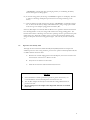
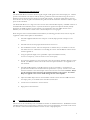
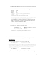
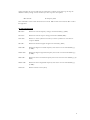
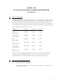
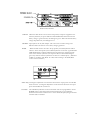
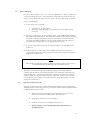
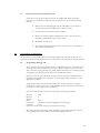
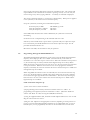
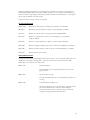
1
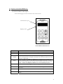
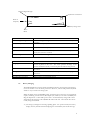
PRAXSYM
Model 5500 Receiver
Model 5700 Transmitter
User’s Manual
February 6, 2002
TABLE OF CONTENTS
1.0
Overview of Model 5500 Receiver
page 3
2.0
Operation of Model 5500 Receiver
page 4
2.1
Control and Indicator Description
page 4
2.2
Battery Charging
page 5
2.3
Operation with AA Dry Cells
page 6
3.0
Making Path Loss Measurements
page 7
4.0
Controlling the Receiver Remotely
page 7
5.0
Definition of Receiver Commands and Error Codes
page 8
6.0
Overview of Model 5700 Transmitter
page 11
7.0
Operation of Model 5700 Transmitter
page 11
7.1
Control and Indicator Description
page 11
7.2
Battery Charging
page 13
7.3
Operation with AA Dry Cells
page 13
7.4
Operation with External Power Source
page 14
8.0
9.0
Programming the Synthesizer
page 14
8.1
Programming Through a PC
page 14
8.2
Programming Through the Model 5500 Receiver
page 15
Definition of Transmitter Commands and Error Codes
page 16
Appendix A - RXScan Software
page 18
2
MODEL 5500
DUAL BAND SIGNAL STRENGTH RECEIVER
USER MANUAL
1.0
Overview of Model 5500
The Model 5500 Signal Strength Receiver is a portable, dual band receiver that measures the strength of
an RF signal. The receiver is capable of measuring signal strengths from -20dBm to -120dBm. The
frequency and signal strength are displayed on the LCD display on the front panel or can be monitored
remotely over an RS232 interface. The receiver and transmitter frequency can be set using the keypad
on the front panel of the receiver or controlled remotely.
These Model 5500 Dual Band Receivers are available:
Part Number
310-010055-002
310-010055-003
Low Band
Cellular band (824 – 894 MHz)
GSM band (925 – 960 MHz)
High Band
PCS band (1930 – 1990 MHz)
DCS band (1805 – 1880 MHz)
The Dual Band Receiver can be used in conjunction with Praxsym’s Model 5700 Dual Band
Transmitter to take path loss measurements in the low band (Cell or GSM) and high band (PCS or
DCS). Typically, the operator decides which frequency to use for testing by scanning the band with the
receiver, identifying vacant frequencies. Once the test frequency is determined, the appropriate
Transmitter Synthesizer Assembly is programmed with the transmit frequency for the test.
Note: If your receiver is the Cellular/PCS model, the term ‘low band’ will refer to the Cellular band and
‘high band’ will refer to the PCS band. Likewise, in the GSM/DCS model, the term ‘low band’ will refer
to the GSM band and ‘high band’ will refer to the DCS band.
3
2.0 Operation of the Model 5500 Receiver
2.1 Control and Indicator Description
See the following figure for the connections and control locations.
Communications port
Shipping switch
Model 5500 Dual Band Receiver
Key Name
ON
OFF
BAND
FREQ
LIGHT
CTRL
F1
F2
Key Function
Press the ‘ON’ key to turn the unit on. The display will indicate the receiver status.
Press the ‘CTRL’ and ‘OFF’ keys simultaneously to turn the unit off.
Press the ‘CTRL’ and ‘BAND’ keys simultaneously to toggle the receiver between
the low and high bands. The display will indicate the active band, and the last tuned
frequency in that band.
Press the ‘CTRL’ and ‘FREQ-UP-ARROW’ keys simultaneously to increment the
receiver frequency up by one step. If these keys are held for more than ½ second,
the frequency will be changed at 10 times the rate, allowing rapid slewing across the
band. ‘CTRL’ and ‘FREQ-DN-ARROW’ moves the tuned frequency down.
Press the ‘LIGHT’ key to toggle the display backlight on and off.
This key is used in conjunction with certain other keys to help prevent accidental
activation.
Reserved
Press the ‘CTRL’ and ‘F2’ keys simultaneously to put the receiver in “TX Program
Mode.”
4
Received Signal Strength
Synthesizer Lock Status
-110 dBm
Receiver
Frequency
Freq:
Band:
Battery Charge State
Active
Band
Indicator
Received Signal Strength
Receiver Frequency
Function
Indicates the signal strength of the channel the Receiver is currently tuned
to receive.
Indicates the frequency of the channel the Receiver is tuned to receive.
Active Band
Indicates the active frequency band.
Synthesizer Lock Status
Indicates the lock status of the Synthesizer PLL. When the padlock is
closed, the synthesizer is locked.
Indicates the current charge state of the batteries.
Battery Charge State
Connection
Shipping Switch
Communications Port
Charger Jack
Low RF Input Connector
High RF Input Connector
2.2
Function
The shipping switch should be placed in the OFF position whenever the
receiver is placed in the case. The switch prevents discharge of the
batteries should the ON key on the front panel be inadvertently pressed.
RJ45 modular jack for serial communications to the receiver. See Sections
4.0 and 5.0.
Jack for connection to 9V AC/DC adapter for battery charging. See
Section 2.2.
TNC connector for low band antenna
SMA connector for high band antenna
Battery Charging
The Dual Band Receiver is fully operational while the batteries are being charged. Charging
can occur whether or not the unit is powered on. However, with the unit powered off, there
will be no way to monitor the charge cycle.
When the display shows “BATTERY LOW”, the battery has less than 10% of its maximum
capacity remaining. Connect the AC/DC adapter (9V /300mA) to the unit’s CHARGE jack.
Plug the adapter into a 115V 60 Hz power outlet. An internal battery charger will control
and terminate the charging of the 4 NiMH cells within each unit. Allow about three hours
to fully charge the batteries.
A.) The charge cycle begins in the charge pending phase. For a period of time, the battery
display area may alternate between displaying the normal battery bar and the message
5
“CHARGING.” During this time, the charging circuitry is conditioning the battery
before entering the fast charge phase.
B.) In the fast charge phase, the message “CHARGING” appears on the display. The time
to achieve a full charge will depend upon the amount of charge remaining on the
battery.
C.) Once the batteries are fully charged, the message “CHARGING” is replaced by charge
bar. In this mode the battery charger will maintain battery charge using a pulse trickle
mode as long as the adapter is plugged into the Battery Box.
If the AC/DC adapter is connected while the Receiver is in operation and after the batteries
have discharged below 4 volts, the charger will remain in the charge pending phase. The
batteries will continue to discharge since the unit’s operating current is greater than the pulse
trickle charge rate. When this condition occurs, turn the unit off until the batteries have
charged to the point that the fast charge phase begins. The unit may then be turned back
on.
2.3
Operation with AA Dry Cells
Although the four internal AA Nickel Metal Hydride (NiMH) batteries should provide
sufficient power for most testing situations, provision for operation with disposable lead acid
or alkaline batteries has been made.
A. With the unit off and unplugged from the wall adapter, remove the four #8 screws
from the back of the receiver. Remove the lid.
B. Fully remove the batteries in the holder.
C. Install the new batteries and reinstall the lid and screws.
NOTES
•
•
•
If the 5500 Receiver will be operated for periods of greater than 6 hours, it is
recommended that the AC/DC adapter be connected to the unit.
The AC/DC Adapter should only be used while the rechargeable batteries are
present in the unit.
Do not attempt to use the adapter when disposable batteries are installed
in the unit.
6
3.0
Making Path Loss Measurements
The Model 5500 Receiver measures absolute signal strength of CW signals at the antenna input port. Relative
path loss measurements can easily be made by selecting a reference location and then moving the receiver to
different locations while noting the change in received signal strength. To measure actual path loss, the user
must take into account the gain of the antennas being used on both the transmitter and receiver and the output
power of the transmitter.
The Model 5500 Receiver is a single conversion receiver with an intermediate frequency of 90MHz. Because of
the bandwidth of the SAW filter, there is very little attenuation of signals in the adjacent channel (30 kHz).
Signals that are 60kHz from the receiver frequency are attenuated by more than 40dB. Because of this
limitation, the user should not conduct tests in a channel adjacent to a strong signal.
When using the receiver with the Model 5700 Transmitter, the following procedure can be used to setup the
equipment to make relative path loss measurements.
4.0
•
Install the supplied cable between a serial port on the PC/laptop and the serial port on the
receiver.
•
Install the antenna for the proper band and turn the receiver on.
•
Start the RXScan software. Enter the frequencies or channels that you would like to scan and
then initiate the scan. Information on controlling the receiver with the RXScan software can be
found in appendix A.
•
Using the spectrum display or the spreadsheet output of the RXScan software,
choose a test frequency. Tune the receiver to the test frequency.
•
Set up the test transmitter to the test frequency using the procedures outlined in Section 8 of this
manual. The RXScan software can also be used to set up the transmitter. See Appendix A of
this document.
•
Install the 30dB attenuator on the RF OUT port of the test transmitter. (An attenuator is
provided when the Receiver and Transmitter are purchased as a system). Connect a coax cable
from the attenuator to the antenna input of the receiver for the correct band. Caution: Always
use the attenuator when connecting the transmitter directly to the receiver. Too much
RF power applied to the receiver could damage the low noise amplifier.
•
Adjust the AMPL ADJ control on the transmitter until the receiver measures 30dB lower then
the output power you would like at the transmitter antenna base.
•
Connect the test transmitter to the test antenna.
•
Begin path loss measurements.
Controlling the Receiver Remotely
The receiver can be controlled by a PC or embedded controller via the RS232 interface. The RXScan software
included with the receiver can be used to control the receiver for most applications. Procedures in this section
also describe control with terminal emulation software on a PC or laptop computer.
7
•
Install the supplied cable between a serial port on the PC/laptop and the serial port on the
receiver.
•
Start the terminal emulation software and setup with the following parameters.
Baud rate
9600
Data bits
8
Stop bits
1
Parity
none
Comm port
whichever one cable is plugged into on PC/laptop
Local echo
ON
Select line feed (LF) after carriage return (CR) when receiving
The settings may be found in various places depending on the terminal emulation software
used. Generally, check the Serial Port and Terminal configuration menus.
Power up the Receiver by depressing the ‘ON’ button. The software will respond with
“RDY” or a similar message. You can verify the current settings at any time by typing
“HELP?” A summary of commands is also displayed.
The receiver frequency is stored in non-volatile memory. When power is applied to the
receiver, it will return to the last entered frequency.
•
Set up the receiver, following the recommended sequence:
Set the target band
Set the frequency in MHz
Verify the frequency is locked
BD=X<CR> (0=low band, 1= high band)
FR=XXXX.yyy<CR>
LD?<CR>
See Section 5.0 for a complete listing of all commands and error codes.
5.0
Definition of Receiver Commands and Error Codes
Put the keyboard in ‘all CAPS’ mode before entering commands. <CR> represents ‘ENTER.’
SET COMMANDS
The response to all SET commands or a <CR> is the message OK <CR>.
FR = XXXX.yyy<CR>
Set receiver frequency (in MHz)
Inclusion of the decimal point and digits to the right of the decimal are optional. CAUTION: The
synthesizer frequency must be divisible by the step size (ST) and must be resent after each step size
change. See note in ST description. The receivers ‘IF’ frequency is added to this number to
determine the synthesizer frequency.
ST= X.XXX<CR>
Set frequency step size (in MHz)
Leading zeroes and the decimal point are required. Trailing zeroes are optional. CAUTION: This
step size is the synthesizer stepsize. Step sizes are set at the factory. It is not advisable to change the
8
setting. Changing the step size will cause the synthesizer to unlock. Upon power up, the step size
defaults to factory settings. Contact the factory if other step sizes are required.
BD=X<CR>
Set frequency band
This command is used to select the band to be received. BD=0 selects the low band. BD=1 selects
the high band.
QUERY COMMANDS
FR?<CR>
Returns the current frequency setting in the form XXXX.yyy (MHz).
ST?<CR>
Returns the current step size setting in the form X.XXXX (MHz).
LD?<CR>
Returns “1” if the synthesizer is locked, “0” if the synthesizer is not locked or
output is disabled.
SS?<CR>
Returns the measured signal strength in the form XX.y (dBm.)
MX?<CR>
Returns the highest ‘low band’ frequency that can be set in the form XXXX.yyyy
(in MHz).
MX2?<CR>
Returns the highest ‘high band’ frequency that can be set in the form XXXX.yyyy
(in MHz).
MN?<CR>
Returns the lowest ’low band’ frequency that can be set in the form XXXX.yyyy (in
MHz).
MN2?<CR>
Returns the lowest ‘high band’ frequency that can be set in the form XXXX.yyyy
(in MHz).
VR?<CR>
Returns software version (X.X)
9
ERROR RESPONSES:
Invalid commands will be acknowledged with an error response. An error response will consist of 4
ASCII bytes followed by a carriage return. The error code consists of the two characters ER followed
by a two-character error status code.
ERIC<CR>
Invalid command
The command was not recognized because it was not in the proper
format.
ERIN<CR>
Invalid number or range
The data included in the previous command was invalid or out-of-range.
ERSE<CR>
Communications (UART) error
The last command was not recognized due to a framing error in the serial
communications. This error will normally be encountered when the
host’s serial port does not match the serial port settings specified in this
document.
10
MODEL 5700
DUAL BAND, BATTERY-POWERED TRANSMITTER
USER MANUAL
6.0
Overview of Model 5700
The Model 5700 consists of two Synthesizer Assemblies (one low band- Cellular or GSM and one high
band- PCS or DCS) and the RF Leveling and Battery Box. The Battery Box (Praxsym part number
310-010054) provides power and RF switching and leveling for the Synthesizer Assemblies (contact
Praxsym for part numbers and availability of synthesizer assemblies for other bands). The battery box
is also supplied with an AC/DC adapter (Praxsym part number 500-023000) for charging the batteries.
Factory settings for the Synthesizers are as follows:
Synthesizer
Frequency
Output Level
Step Size
Cellular
(824-894 MHz)
875 MHz
+5 dBm
10 kHz
Extended Cellular
(805-894 MHz)
875 MHz
+5 dBm
10 kHz
GSM
(880-960 MHz)
921 MHz
+5 dBm
10 kHz
PCS
(1930-1990 MHz)
1960.2 MHz
+5 dBm
30 kHz
Extended PCS
(1850-1990 MHz)
1960.2 MHz
+5 dBm
30 kHz
DCS
(1710-1880 MHz)
1785 MHz
+5 dBm
30 kHz
Typically, the operator decides which frequency to use for testing. This can be accomplished by
scanning the band with the Dual Band Receiver. Once the test frequency is determined, the
appropriate Synthesizer Assembly is programmed with the transmit frequency for the test.
7.0
Operation of the Model 5700 Transmitter
7.1
Control and Indicator Description
See the following figure for the connections and control locations. A description of each
function is given below.
11
Model 5700 Transmitter
POWER -When the slide switch is moved to the ON position, and power is applied to the
selected synthesizer, the power indicator LED will illuminate. When the internal
battery voltage is greater than 8V, the LED glows green. When the internal battery
voltage drops below 8V, the LED glows red.
CHARGE -Input jack for the AC/DC adapter. This section also contains a charge state
indicator LED. See Section 7.2 for battery charging operation.
BAND
- When the slide switch is moved to the up position, the PCS Synthesizer will be
selected. In the down position, the Cellular Synthesizer is selected. A green BAND
LED will illuminate to indicate which band is selected for the operation and the
status of the selected synthesizer. The respective PCS or CELL LED will glow
green only when the selected synthesizer is locked on a valid frequency. (Substitute
“GSM” for “Cellular” and “DCS” for “PCS” when refering to the GSM/DCS
version of the transmitter.)
AMPL ADJ -Turning this adjustment screw clockwise increases the output power from the RF
OUT connector. Turning this adjustment counter-clockwise decreases the output
power from the RF OUT connector.
TUNING
-The individual synthesizers must be selected in order to be programmed. Set the
POWER switch to ON and position the band switch prior to programming.
Follow the Instructions in Section 8.0 to set the desired frequency using an external
controller and a serial cable.
12
7.2
Battery Charging
Connect the AC/DC adapter (15V / 1A) to the unit’s CHARGE jack. Plug the adapter into
a 115V 50/60 Hz power outlet. An internal battery charger will control and terminate the
charging of the 8 NiMH cells within each unit. Allow 1.5 hours to fully charge the batteries.
Charge cycle description:
A.) A new charge cycle is started by:
1.
2.
Connecting the AC/DC adapter.
The battery voltage dropping to 8 volts with the AC/DC adapter already
connected.
B.) The charge cycle begins in the charge pending phase. The CHARGE LED will blink
during the charge pending phase. The charger circuit trickle charges the batteries during
this phase as it prepares the batteries for the fast charge phase. If the batteries had
previously been discharged below 8 volts, the charge pending phase will continue to
trickle charge the batteries until they are charged back up to 8 volts.
C.) In the fast charge phase, the batteries are charged at 900mA. The CHARGE LED
remains on.
D.) Once the batteries are fully charged, the CHARGE LED goes off and the battery
charger will maintain battery charge using a pulse trickle mode as long as the adapter is
plugged into the Battery Box.
NOTE
If the Model 5700 Transmitter will be operated for periods of greater than 4 hours, it is
recommended that the AC/DC adapter be connected to the unit.
Although the transmitter may be operated during charging, if the AC/DC adapter is
connected after the batteries have discharged below 8 volts, the charger will remain in the
charge pending phase. The batteries will continue to discharge since the unit’s operating
current is greater than the pulse trickle charge rate. When this condition occurs, turn the
unit off until the batteries charge to the point that the fast charge phase begins. The unit
may then be turned back on.
7.3
Operation with AA Dry Cells
Although the eight (8) internal AA Nickel Metal Hydride (NiMH) batteries should provide
sufficient power for most testing situations, provision for operation with disposable lead acid
or alkaline batteries has been made.
•
With the unit off and unplugged from the wall adapter, remove the four
screws from the back of the Battery Box. Remove the lid.
•
Fully remove the batteries in the two holders.
•
Install the new batteries and reinstall the lid and screws.
•
Do not attempt to use the charger when disposable batteries are
installed in the unit.
13
7.4
Operation from an External Power Source
If the unit is to be operated continuously from the supplied wall adapter and battery
operation is not desirable, the following steps may be taken to operate without internal
batteries.
8.0
•
With the unit off and unplugged from the wall adapter, remove the four
screws from the back of the Battery Box. Remove the lid.
•
Carefully remove the batteries in the two holders.
•
Remove the shorting jumper installed between pins 1 and 2 on JP1 and
reinstall the jumper between pins 2 and 3 on JP1.
•
Reinstall the lid and screws.
•
The external wall adapter will now be the sole power source for the Battery
Box and attached synthesizers.
Programming the Synthesizers
The procedures for programming either the low band or high band synthesizer are identical. It is
expected that procedures will remain the same for synthesizers to be developed for other frequencies.
8.1
Programming Through a PC
The synthesizers can be programmed via a PC or embedded controller. Procedures in this
section describe setup of synthesizers with a PC or laptop computer as the host interface.
The synthesizers are programmed using simple ASCII commands from a terminal program.
See Appendix A to program the transmitters with the RXScan software.
Select the correct frequency band with the slide switch on the front of the Battery Box.
Install the serial cable between a serial port on the PC/laptop and the serial port on the
appropriate synthesizer.
Verify that the cable harness between the Battery Box and the synthesizers is properly
installed. The 15-pin connector goes in the PWR/DATA port in the Battery Box and the
two 25-pin connectors plug into the synthesizers.
Start the terminal emulation software and setup with the following parameters.
Baud rate
9600
Data bits
8
Stop bits
1
Parity
none
Comm port
whichever one cable is plugged into on PC/laptop
Local echo
ON
Select line feed (LF) after carriage return (CR) when receiving
The settings may be found various places depending on the terminal emulation software
used; generally, check the Serial Port and Terminal configuration menus.
14
Power up the unit with the slide switch on the front of the Battery Box. The software will
respond “RDY” if the communications channel is operating correctly. You can verify the
current settings at any time by typing “HELP?” A summary of commands is displayed.
The current synthesizer frequency is stored in non-volatile memory. When power is applied
to the synthesizer, it will return to the last entered frequency.
Set up the synthesizers, following the recommended sequence:
Set the frequency in MHz
Verify the transmitter is enabled
Verify the frequency is locked
FR=XXXX.yyyy<CR>
TX?<CR>
LD?<CR>
If the LED beside the band select switch is illuminated, the synthesizer is locked and
transmitting.
See Section 9.0 for a complete listing of all commands and error codes.
If desired, connect the RF OUT to power meter or spectrum analyzer to adjust the output
level. Alternatively, the Model 5500 Receiver can be used to adjust the output. See the
procedure described in Section 3.0.
Disconnect serial cable; the transmitter is ready for operation.
8.2
Programming Through the Model 5500 Receiver
The Model 5500 Signal Strength Receiver can be used to setup the Model 5700 Transmitter
frequency when a laptop or PC is not available. This function only works when the
transmitter is set to the same step size as the receiver. When the transmitter is first powered
on, the low band step size is always 10kHz and the high band step size is always 30kHz.
When the receiver is first powered on, the step size is set to the step size that was used when
it was powered down. Whenever the receiver is to be used to program the transmitter
frequency in the field, the user must insure that the receiver low band step size is 10kHz and
the high band step size is 30kHz.
When using RXSCAN software version 2.0 and earlier, the user must insure that that step
size is set to the desired value by manually typing in the desired step size in the command
box located in the upper right hand corner of the window. This is necessary following any
band scan due to an error in the code the resets the low band step size to 10kHz and the
high band step size to 100kHz.
Cable connections and power up:
1) Turn on the receiver and the transmitter
2) If programming in the low band, switch the transmitter selector to “CELL”. If
programming in the high band, switch the transmitter to “PCS”. (Substitute “GSM” for
“CELL” and “DCS” for “PCS” if using the GSM/DCS transmitter.)
3) Using the supplied modular cable, install the modular adapter labeled “TX” onto one end.
Plug the other end into the receiver.
4) Plug the “TX” adapter into the appropriate connector, depending on switch position set
in step 2. The low band and high band transmitters are two independent units, so if a low
band frequency is to be programmed, the switch on the transmitter must be in the down
15
position. If a high band frequency is to be programmed, the switch must be in the up
position.
Polling the Transmitter:
The user can poll or query the transmitter for its current frequency setting. Press “CTRL”
and “F2” simultaneously. The receiver will display “TX PROGRAM MODE” and the
current frequency setting for the transmitter.
If the transmitter is already set on the desired frequency, exit the program mode by pressing
“CTRL” and “F2” simultaneously.
Programming:
To change the broadcast frequency of the transmitter, change the receiver frequency (press
“CTRL” and an arrow key simultaneously). The first time you press the “CTRL” and arrow
combination, the transmitter and receiver are now set to the same frequency. Subsequent
“CTRL” and arrow key combinations will increase or decrease the frequency setting in both
the receiver and transmitter. To exit from this mode, press "CTRL" and "F2" again. Now
the receiver frequency can be changed with no effect on the transmitter.
Precautions:
The transmitter could lock up if given incorrect data very quickly. This affects operation in
the following way:
If attempting to program the transmitter to a low band frequency while in high
band range on the receiver, this obviously results in an error condition. If the user
rapidly changes the frequency (resulting in rapid invalid frequency assignments to
the transmitter) the transmitter will lock up, and not respond to input.
If lock up should occur, shut off the power to the transmitter (flip the switch to the
off position) and turn it back on.
9.0
Definition of Transmitter Commands and Error Codes
SET COMMANDS
The response to all SET commands or a <CR> is the message OK <CR>.
FR = XXXX.yyyy<CR>
Set synthesizer frequency (in MHz)
Valid frequencies are listed in the HELP? inquiry. Inclusion of the decimal point and digits to the
right of the decimal are optional. CAUTION: The synthesizer frequency must be divisible by the
step size (ST) and must be resent after each step size change. See note in ST description.
TX=X<C>
Enable/Disable output
The ‘Enable/Disable output’ command is used to turn off the output by disabling the power to the
VCO. TX=1 turns the output on. TX=0 turns the output off. Upon power up, TX=1 and the
output is enabled.
ST= X.XXX<CR>
Set frequency step size (in MHz)
Valid step sizes are listed in the HELP? inquiry. Leading zeroes and the decimal point are required.
Trailing zeroes are optional. CAUTION: Step sizes are set at the factory. It is not advisable to
16
change the setting. Changing the step size will cause the synthesizer to unlock. The transmitter is
automatically disabled (TX=0) after a ST=X.XXX command. A new frequency (FR=XXXX.yyyy)
must be sent after a step change, followed by an enable transmitter command (TX=1). Upon power
up, the step size defaults to factory settings.
Contact the factory if other step sizes are required.
QUERY COMMANDS
HELP?<CR>
Returns text showing current settings and a summary of commands.
FR?<CR>
Returns the current frequency setting in the form XXXX.yyyy (MHz).
ST?<CR>
Returns the current step size setting in the form X.XXXX (MHz).
LD?<CR>
Returns “1” if frequency is locked, “0” if the frequency is not locked or
output is disabled.
TX?<CR>
Returns “1” if the frequency is enabled, “0” if the output is disabled.
MX?<CR>
Returns the highest frequency that can be set in the form XXXX.yyyy (in MHz).
MN?<CR>
Returns the lowest frequency that can be set in the form XXXX.yyyy (in MHz).
VR?<CR>
Return software version (X.X)
ERROR RESPONSES:
Invalid commands will be acknowledged with an error response. An error response will consist of 4
ASCII bytes followed by a carriage return. The error code consists of the two characters ER,
followed by a two-character error status code.
ERIC<CR>
Invalid command
The command was not recognized because it was not in the
proper format.
ERIN<CR>
Invalid number or range
The data included in the previous command was invalid or outof-range.
ERSE<CR>
Communications (UART) error
The last command was not recognized due to a framing error in
the serial communications. This error will normally be
encountered when the host’s serial port does not match the
serial port settings specified in this document.
17
Appendix A
RXScan Software
1.0
Using the RXScan Software
1.1
Installing the Software
Note: Before installing, it is recommended to visit http://www.praxsym.com/software.html
and check for newer versions of RXScan as well as updates to this manual.
The RXScan software is supplied on CD. Run the file “setup.exe”. For optimum
performance, install the program to the default directory “C:\Program Files\RXScan”. For
the latest information on the software, read the “Readme.txt” file that comes with the setup
files. After the setup program has finished installing the software, you may delete the setup
files in the temporary directory that you created. RXScan may now be accessed via Start
Menu/Program Files/RXScan/RXScan.exe.
2.0
Setup for Receiver
2.1
Hardware Setup
Before pushing the “Scan” button on the RXScan PC software, the following hardware
considerations should be checked:
1) The Model 5500 Signal Strength Receiver should be turned on.
2) An antenna or some type of signal source should be connected to either the low band
or the high band antenna ports on the receiver.
The modular plug of the supplied serial cable should be connected to the receiver, while the
9-pin DSUB connector should be connected to a free comm port on the PC.
2.2
Connecting to the Receiver
Click on File/Connect Receiver. This action will bring up the connection form. If the comm
port hooked up to the serial cable is not labeled on the outside of the computer, then try
Comm1 first. If this port is already in use or does not exist, an error message should result
when attempting to open it.
2.3
Connecting optional GPS support
RXScan is compatible with the NMEA GPS sentence structure. RXScan processes the
$GPRMC output string used with the NMEA format. To use the GPS ability of RXScan,
do the following:
1)
2)
3)
Configure your GPS to put out NMEA data at 4800 baud.
Connect the serial port of the GPS to a free COM port on the host PC.
Select File/Connect GPS. When the 'Open COM port' dialog box appears, enter the
COM port number that the GPS is attatched to, and click 'OK'.
The 'Latitude' and 'Longitude' labels on the 'Frequency Bank' tab should now update once
every second. If the GPS has not acquired a fix, the labels should display 'Getting Fix'.
Once valid data is received, the labels should show the latitude and longitude.
18
RXScan was tested with Garmin's eMap GPS. With the Garmin eMap GPS, it can be
configured for indoor use, where it outputs the last known latitude and longitude.
2.4
Model and Scan Range Selection
Now that the comm port is open, go to ‘Settings’ and choose the appropriate receiver
model. To scan a CELL range, click the “Receiver Cell” tab near the top of the window. To
scan a PCS range, click the “Receiver PCS” tab. If you have the GSM/DCS model, you will
have GSM and DCS tabs. To select the frequency range, either type in a valid channel into
the “Scanning Range (Channel)” box, or type a valid frequency into the Frequency Scan
Range box. The leftmost box sets the lower bound of the scan range, while the rightmost
box selects the upper bound. If using the Channel scanning range boxes, the Mode box
determines whether the channel is interpreted as a Mobile or a Base channel.
3.0
Scanning
After the range has been selected, press the Scan button. The raw data communications with the
receiver can be seen in the “Terminal” window to the right of the main window. The frequency being
scanned is displayed in the window marked “Current Freq”. When the software is done scanning the
selected range of frequencies, it opens up Microsoft Excel and writes the data to a new worksheet.
NOTE: Every time the software scans a range of frequencies, it writes to a NEW workbook.
19
The data that was gathered from the receiver is now stored in an Excel workbook. It can be saved by
accessing File/Save As in Microsoft Excel.
4.0
Using Frequency Bank
The Frequency Bank option allows the user to select up to six frequencies to monitor. Each time the
‘Scan’ button is selected, readings are taken and can then be logged to an Excel file. A user label tag is
used to identify the corresponding scan location. GPS information (see section 2.3) and time stamp
can also be implemented.
20
A combination of high band and low band frequencies can be monitored in the Frequency Bank. To enable a
frequency for monitoring, the box to the left of the step size must be checked. Once the box is checked, the
label will read ‘Enabled’ and the indicator will change to green. When the SCAN button is selected, each
enabled channel is scanned once and the measured signal strength is displayed. A label can be added to each
scan to help identify the location or other information important to the scan. Once your label has been
entered, the data can be appended to the active log file by selecting the LOG TO FILE button. If the LOG
TO FILE button is not selected, the data from the scan will not be saved. An example of an Excel log file is
shown below.
21
5.0
Programming the Model 5700 Transmitter
The RXScan Software can program the Model 5700 Transmitter. The transmitter should be turned
on. A serial cable should be connected to the appropriate serial port on the transmitter and to a free
comm port on the PC. Click on the “Transmitter” tab near the top of the program window. After
clicking on this tab, a message window should appear reminding the user that the communications
cable needs to be disconnected from the receiver and connected to the transmitter. The transmitter
interface simply sends commands to the transmitter, displaying the command and the resulting answer
in the “Communications” window adjacent to the main program window.
6.0
Transmitter Frequency Selection
To change the transmitter frequency, select the desired frequency from the transmitter box, and push
the “Send” button. Be sure that the correct band is selected on the transmitter.
22